dot air-cons cad guidelines 012809 c. paper space and model space paper space paper space is one of...
TRANSCRIPT

DEPARTMENT OF TRANSPORTATION
AIRPORTS DIVISION
CONSULTANTCAD GUIDELINES
JANUARY 2009


TABLE OF CONTENTS I. INTRODUCTION 1
A. DEPARTMENT OF TRANSPORTATION - AIRPORTS DIVISION MISSION STATEMENT 1
B. AIRPORTS DIVISION GOALS 1
C. AIRPORTS BASEMAP COORDINATE SYSTEM 1
D. OVERALL INTENT AND BENEFITS OF GUIDELINES 1
II. CAD STANDARDS 2
A. CAD FILE TRANSFER PROCEDURES AND POLICIES 2
B. FILE NAMING CONVENTION 4
C. PAPER SPACE AND MODEL SPACE 5
D. EXTERNAL REFERENCE FILE (XREFs) 5
E. LAYERING SYSTEM 6
F. GRAPHIC SYMBOLS, FONT STYLES & LINETYPES 12
1. SYMBOLS 12
2. FONT STYLE 12
3. LINETYPES 12
G. DRAWING SET UP 12
H. RECORD DRAWINGS 15
CAD QUALITY ASSURANCE CHECKLIST 17
APPENDIX A - SAMPLE OF TITLE SHEET AND STANDARD BORDER 19
APPENDIX B - SAMPLE OF TITLE SHEET BORDER WITH AS-BUILT INFORMATION 25


1
I. INTRODUCTION
A. DEPARTMENT OF TRANSPORTATION - AIRPORTS DIVISION MISSION STATEMENT.
The mission of the Department of Transportation - Airports Division is to develop and maintain graphic and related information such that users can manage, operate, maintain and improve the State Air Transportation System thus providing safe and efficient air travel to the public.
B. AIRPORTS DIVISION GOALS
The Airports Division goal includes maintaining up-to-date information on the central master CAD files. These files are to be used as a resource to share within the organization as well as authorized Consultants in the public sector.
C. AIRPORTS BASEMAP COORDINATE SYSTEM
All State of Hawaii Airports AutoCAD Basemap drawings have been converted into North American Datum of 1983 High-Accuracy Reference Network (NAD83 HARN) Coordinate System. There are 3 (three) coordinates as noted in the basemap drawings that have been surveyed with NAD83 HARN Coordinate System.
D. OVERALL INTENT AND BENEFITS OF GUIDELINES
1. The purpose of this Consultant Guidelines is to provide consistent graphical information to and from the Department of Transportation - Airports Division. This will facilitate the timely access and delivery of information to internal and external users, provide means to update graphic information quickly, and to serve as a consistent guide for producing and delivering CAD drawings to the Department of Transportation - Airports Division.
2. This guideline shall apply to all individuals and State Government units who perform
drafting and graphics services for Department of Transportation – Airports Division Engineering (AIR-E).
3. The purpose of the workflow policies are to assist the AIR-E staff to maintain an up-to-date
central database of the State of Hawaii Airports and to be able to monitor timely return of built conditions from construction or maintenance improvements at each site.

2
II. CAD STANDARDS A. CAD FILE TRANSFER PROCEDURES AND POLICIES
The intent of the Policy Guidelines is to assist the Airports Division to maintain the most current central resource of all State of Hawaii Airports as well as maintain records for accountability. The Policies are established to assist the workflow process and monitor timely return of built conditions from construction or maintenance improvements at each site. All documentation drawings and construction project drawings must be submitted to AIR-E in full compliance with their most current version of AutoCAD (file extension = .dwg). Throughout this document, the use of the name CAD always implies AIR-E’s current version, unless otherwise noted.
CONSULTANTS (OUTSIDE PARTIES) CAD DRAWINGS/FILES REQUESTS PROCEDURES
1. Consultants (Outside Parties) may request from State Project Manager a copy of a specific
area of the airport in a CAD format to execute their approved contract work. State Project Manager will send the Outside Parties the Request for Airports Plans and CAD/Computer Graphics Data and Recipient’s Indemnification Clause Forms. A diagram of the Airport may be attached. This diagram should be used by the Outside Parties to show the extent of site needed.
2. Outside Parties shall fill out, sign and submit the Request for Airports Plans and
CAD/Computer Graphics Data, Confidentiality and Non-Disclosure Agreement, Recipient’s Indemnification Clause Forms and Airport diagram (if any) to the State Project Manager.
3. State Project Manager will review, verify the information filled in by the requestor and sign
the Request for Airports Plans and CAD/Computer Graphics Data Form.
4. DOTA Engineers will make a copy of the approved Request for Airports Plans and CAD/Computer Graphics Data, Confidentiality and Non-Disclosure Agreement, and Recipient’s Indemnification Clause Forms to AIR-EG.
5. AIR-EG will email the requested CAD files/drawings to the requestor.
6. Outside Parties will modify the copy of CAD files per project contract requirements.
7. After construction is completed, the Outside Parties will prepare their project drawings in
accordance with DOTA Consultant CAD Guidelines and submit As-Built drawings to State Project Manager. If necessary, DOTA will send pertinent CAD base files back to requestor for updating which requestor will be requiring to show as-built conditions and submit back to DOTA.
CAD BASEMAP FILE TRANSFER POLICIES 1. AIR-E shall name file with a consultant ID prefix to the original basemap CAD file name.
a. For example, Consultant XYZ will receive a file named: XYZ-hnl-level01-terminalA.dwg
2. Copies of CAD basemap files shall not be released outside the Airports Division without
State Project Manager approval and signature.

3
3. Only the Designer should request CAD basemap files and responsible for distributing the CAD basemap files to their sub-consultants.
CAD FILES SUBMITTED TO AIR-E:
1. Any As-Built changes should be submitted in the latest CAD format to State Project
Manager within 3 (three) months of final construction completion. Larger projects shall be given more time based on State Project Manager approval.
2. All Consultants are required to submit As-Built drawings to State Project Manager in a
timely manner. 3. All drawings submitted shall comply with the Consultant CAD Guidelines. CAD files shall
follow the file naming convention on next page.

4
B. FILE NAMING CONVENTION Airport ID codes are assigned as follows: hdh Dillingham Airfield hnl Honolulu International Airport hnm Hana Airport ito Hilo Airport jhm Kapalua Airport jrf Kalaeloa Airport koa Kona International Airport lih Lihue Airport lny Lanai Airport lup Kalaupapa Airport mkk Molokai Airport mue Waimea-Kohala Airport ogg Kahului Airport pak Port Allen Airport upp Upolu Airport
Outside Parties (Consultant) ID codes will be assigned by AIR-E:
Each Outside Parties who requests a copy of a portion of the Master CAD base will be issued a 3 character ID.
Consultant’s File Naming Convention:
xxx–-xxx-xxxxx01.dwg Drawing Extension Floor Level – may incl. terminal or area designator Drawing Description Airport’s ID Code Consultant’s 3 character ID Code
The Outside Parties are required to submit the modified CAD base with As-built conditions to AIR-E with the 3 character ID naming convention.

5
C. PAPER SPACE AND MODEL SPACE PAPER SPACE
Paper space is one of two main spaces in which AutoCAD objects reside. Paper space is used to create a finished layout for plotting, sometimes having more than one view with more than one scale on a sheet. Listed below are some items that should be placed in Paper Space:
1. Sheet borders, insert at actual size. 2. Detail blow up grid bubbles. 3. Dimensions. 4. Notes that are specific to that drawing. 5. North Arrow. 6. Schedules.
MODEL SPACE
Model Space is used to do drafting/design work and to create two or three-dimensional models. Everything in Model Space is drawn at full scale. Listed below are some items in Model Space:
1. External Reference Files 2. Drawing entities.
D. EXTERNAL REFERENCE FILE (XREFs)
• All external references (xrefs) shall be “overlayed” at 0,0,0 in model space on layer “0”.
• Provide all external references (AutoCAD and images), font styles, and plot style (ctb files) when
submitting As-Built CAD drawings to AIR-E.
• When attaching an Xref, in the “path type” box, select “Relative Path”. Selecting “Relative Path” will allow you to copy or move an intact directory without having to repath each xref.
• When attaching an Xref, name it the exact same name as the drawing file.
• Do not rename the Xref once it has been distributed to others for referencing or editing.

6
E. LAYERING SYSTEM
This section contains a combination of layers from A/E/C CADD Standard, Release 3.0, ERDC/ITL TR-06-X, September 2006, U.S. Department of Transportation Federal Aviation Administration Standard Engineering Drawing Preparation & Support, FAA-STD-002f, June 17, 2005 and Custom Layers based on AIA CAD Layer Guidelines: U.S. National CAD Standard Version 4.0 Layer names consist of a two-character Discipline Designator followed by four-character Major Group and followed by a four-character Minor Group.
A Architectural C Civil D Interior Design E Electrical F Fire Protection G Graphics
K Food Service L Landscape M Mechanical P Plumbing S Structural T Title
C-LUSE-IDEN These recommended layers should be used when submitting CAD drawings to AIR-E. The following guidelines shall be used: 1. Do not increase the width of a polyline to get a heavier line, the thickness of a line is controlled
by the ctb line weight assignments.
2. Do not increase the width of a polyline to poche walls, use a solid hatch.
3. Layer colors and linetypes, are controlled by what they are assigned to in the layer list. Do not force colors or linetypes in your drawings every entity should be set to “bylayer”.
4. Insert blocks with multiple layers on layer “0”, create simple blocks using layer “0”. See Block
section.
AIR-E requires CONSULTANTS (OUTSIDE PARTIES) to adhere to the following LAYERING PRACTICE:
1. Create new layer D-DEMO, color 13, linetype: hidden 2 for all demolition work. 2. Create new layer(s) for ALL new work by adding an “N” prefix to the appropriate layer name.
e.g. C-PRKG-MRKG is used for the existing parking, if new stalls are added; they would be drawn on layer: NC-PRKG-MRKG.
DISCIPLINE DESIGNATOR MAJOR GROUP MINOR GROUP

7
LAYERING STANDARDS A new layer that will be added to the drawings and is not on the layering standard table below may be added complying with the current A/E/C CADD Standard, Main Text and Appendices A, B, C, ERDC/ITL TR-06-x, Sept. 2006 Release 3.0
Layer Name Layer Description *Name Source
Landuse c-flzo Flood Zone marks CSTM c-luse Landuse Information, Seismic Zones, Land Courts CSTM c-luse-iden Landuse Information, Seismic Zones, Land Courts Annotation CSTM c-luse-ilnd Improved Land - Demarcation Land defining improved land areas CSTM c-luse-plnd Proposed Land Use CSTM c-luse-ulnd Unimproved Land - Demarcation Land defining unimproved land areas CSTM Civil/ Survey c-prop Boundary, Property Lines FAA c-prop-airp Airport Property Lines A/E/C c-prop-cede Ceded Lands CSTM c-prop-cons Control Points, Survey Benchmarks FAA c-prop-esmt Property Easement FAA c-prop-esmt-iden Property Easement Annotation CSTM c-prop-exec Executive Orders CSTM c-prop-exec-iden Executive Orders Annotation CSTM c-prop-iden Property Annotation, Tax Map Key A/E/C c-prop-subd Subdivisions/Parcel/Lots A/E/C c-prop-subd-iden Subdivisions/Parcel/Lots Annotation CSTM Geography c-topo-shor Shorelines, Waterways, Channels and Levees A/E/C c-topo-shor-iden Geograph Annotation CSTM l-plnt Vegetation - Brushes, shrubs, tree lines, Renderings, Individual Trees FAA l-plnt-ctnr Containers or planters CSTM l-plnt-iden Vegetation Annotation A/E/C Aviation c-chan-naid Navigation Aids - Lights, wind cones, segmented circle A/E/C c-obst-airs Obstructions A/E/C
g-avia Primary Surface, Safety Areas, Clear Zones, Approach Slopes, Other Surfaces (Transit/horizon/conical surfaces), Building restriction lines, Obstacle free lines CSTM
g-avia-iden Aviation Annotation CSTM
* LAYER NAMES ONLY FAA = FAA Standard Engineering Drawing Preparation & Support, FAA-STD-002f, June 17, 2005 A/E/C = A/E/C CADD Standard, Main Text and Appendices A, B, C, D ERDC/ITL TR-06-x, Sept. 2006 Release 3.0 CSTM = Custom layer based on FAA & A/E/C standards guide

8
Layer Name Layer Description *Name Source
RunTax
c-runw-edge Paved Area Edges (AOA pavement edge), Run Tax Edges (Load-bearing area defining lines), Airfield Runway Edges A/E/C
c-runw-edge-subd Subdivision of Runway Edge CSTM
c-runw-iden Paved Area Edges (AOA pavement edge), Run Tax Edges (Load-bearing area defining lines), Airfield Runway Edges Annotation A/E/C
c-runw-misc-mrkg Misc AOA markings - General Aviation Tiedown/Ramp Equipment Prkg, CSTM
c-runw-mrkg Run Tax Markings (Runway/Taxiway/Taxilanes/Heliports), Shoulder Markings (Shoulder/Demarcation/Ramp/Roads), Run Tax Demarcation Lines CSTM
Road c-prkg-curb Parking islands, curbs, and gutters A/E/C c-prkg-iden Parking Lot Annotation A/E/C c-prkg-mrkg Parking markings - Stall stripes, hatchings A/E/C c-road Road edges – Lines of invert or pavement edge FAA c-road-curb Curbs and gutters A/E/C c-road-cntr Road Baselines (Center of Road Line), Demarcation Line A/E/C c-road-gral Guard rails A/E/C c-road-iden Road Baselines (Center of Road Line), Demarcation Line, Breaklines (Road Cutlines) Annotation A/E/C c-road-mrkg Road Markings - Land stripes, directional arrows A/E/C c-road-mrkg-subd Road Marking Dividing Line CSTM c-road-unpv Unpaved Road Edges CSTM c-road-otln Road Outline CSTM c-site-iden Overall site annotation CSTM c-site-strc Bridges/tunnels - Bridges, tunnels, headwalls, Retaining walls A/E/C c-site-walk Walkway Edges - Paved walkways A/E/C l-site-furn Built -in details, Free-standing details - Landscape, furniture, equipment FAA General a-anno-note General Notes A/E/C a-anno-dims Dimensions A/E/C a-grid Grid Lines, Coordinates, Column Grids CSTM a-grid-bubb Grid Bubbles CSTM a-symb Symbols - Building Sections, Wall Sections, Call Out Details CSTM Building a-area-iden Room Numbers, Tenant Identifications, Area Calculations A/E/C a-area-line Area Calculation boundary lines A/E/C a-eqpm-fixd Fixed Equipment A/E/C a-flor-evtr Elevator cars and equipment A/E/C a-flor-fixt Plumbing Fixtures A/E/C a-flor-hral Stair and balcony handrails, guard rails A/E/C a-flor-levl Level changes, shafts, ramps, pits, breaks in construction and depressions A/E/C
* LAYER NAMES ONLY FAA = FAA Standard Engineering Drawing Preparation & Support, FAA-STD-002f, June 17, 2005 A/E/C = A/E/C CADD Standard, Main Text and Appendices A, B, C, D ERDC/ITL TR-06-x, Sept. 2006 Release 3.0 CSTM = Custom layer based on FAA & A/E/C standards guide

9
Layer Name Layer Description *Name Source
Building a-furn Built-in Details CSTM a-furn-free Free Standing Details - Landscape, Furniture, Equipment FAA a-flor-numb Room/space identification number and symbol A/E/C a-flor-otln Floor outline/perimeter/building footprint A/E/C a-flor-ovhd Overhead items (skylights, overhangs, etc.), Roof Lines - Roof Edge Above A/E/C a-flor-spcl Architectural specialties (e.g. toilet room accessories, display cases) A/E/C a-flor-strs Stair risers/treads, escalators, ladders a-flor-tptn Toilet Partitions A/E/C
a-flor-wdwk Architectural woodwork (field built cabinets and counters), Built-in Details - Landscape, Furniture, Equipment A/E/C
a-roof Roof Line FAA a-roof-beam Roof beam CSTM a-roof-expj Expansion Joints A/E/C a-roof-rfdr Roof drains and slopes A/E/C a-roof-wall Parapet walls and wall caps A/E/C a-wall Building Walls - Non-Structural or Undefined Structural Walls CSTM a-wall-full-extr Exterior Full Height Wall A/E/C a-wall-full-intr Interior Full Height Wall A/E/C a-wall-prht Partial height walls (do not appear on Reflected Ceiling Plan) A/E/C a-wall-spcl Wall-hung/Attached Specialties (e.g., fixtures, grab bars (incl. handicap), Telephone Booths A/E/C a-wall-subd Subdivisions of rooms/ spaces CSTM a-wwdr Doors and Windows CSTM c-bldg-iden Building Annotation A/E/C c-bldg-otln Building Outline A/E/C c-dema Bldg demarcation lines CSTM c-hang Hangar CSTM c-hang-subd Subdivision of Hangar CSTM c-site-brdg Loading bridges/ Jetway A/E/C Secure c-site-fenc Security Fences (Fences, Perimeter Gates) A/E/C c-site-aoap AOA Perimeter - Closed Line Defining AOA CSTM Utility c-domw-abnd-pipe Abandoned piping CSTM
c-domw-devc Connectors, faucets, reducers, regulators, vents, intake points, taps, backflow preventers, valves, cut and cap A/E/C
c-domw-fttg Caps, cleanouts, crosses, and tees A/E/C c-domw-hydr Hydrants A/E/C
* LAYER NAMES ONLY FAA = FAA Standard Engineering Drawing Preparation & Support, FAA-STD-002f, June 17, 2005 A/E/C = A/E/C CADD Standard, Main Text and Appendices A, B, C, D ERDC/ITL TR-06-x, Sept. 2006 Release 3.0 CSTM = Custom layer based on FAA & A/E/C standards guide

10
Layer Name Layer Description *Name Source
Utility c-domw-iden Identifier tags, symbol modifier, and text CSTM c-domw-main-pipe Main domestic water piping CSTM c-domw-abnd-pipe Abandoned piping CSTM
c-domw-devc Connectors, faucets, reducers, regulators, vents, intake points, taps, backflow preventers, valves, cut and cap A/E/C
c-domw-fttg Caps, cleanouts, crosses, and tees A/E/C c-domw-hydr Hydrants A/E/C c-domw-iden Identifier tags, symbol modifier, and text CSTM c-domw-main-pipe Main domestic water piping CSTM c-domw-metr Meters A/E/C c-fuel-abnd-pipe Abandoned piping A/E/C
c-fuel-devc Air eliminators, filter strainers, hydrant fill points, line vents, markers, oil/water separators, reducers, regulators, and valves A/E/C
c-fuel-fttg Caps, crosses, and tees A/E/C c-fuel-iden Identifier tags, symbol modifier, and text CSTM
c-fuel-main-pipe Main fuel piping CSTM
c-fuel-pits-vlve Valve pits A/E/C c-npot-devc Connectors, faucets, reducers, regulators, vents, intake points, taps, backflow preventers, and valves CSTM c-npot-fttg Caps and cleanouts CSTM c-npot-iden Identifier tags, symbol modifier, and text CSTM c-npot-mhol Manholes CSTM c-npot-pipe Non-potable water piping CSTM c-sswr-abnd-pipe Abandoned piping CSTM c-sswr-fttg Caps and cleanouts A/E/C c-sswr-iden Identifier tags, symbol modifier, and text CSTM c-sswr-mhol Manholes A/E/C c-sswr-main-pipe Sewer piping CSTM c-strm-abnd Abandoned piping CSTM c-strm-devc Downspouts, flumes, oil/water separators, and flap gates A/E/C c-strm-fttg Caps and cleanouts A/E/C c-strm-iden Identifier tags, symbol modifier, and text A/E/C c-strm-inlt Inlets (curb, surface, and catch basins) A/E/C c-strm-main Storm sewer piping A/E/C c-strm-mhol Manholes A/E/C v-comm-abnd Abandoned duct lines CSTM v-comm-duct Communications/telephone duct lines CSTM v-comm-iden Identifier tags, symbol modifier and text CSTM v-comm-jbox Communication junction boxes, pull boxes, manholes, hand holes, pedestals, splices A/E/C
* LAYER NAMES ONLY FAA = FAA Standard Engineering Drawing Preparation & Support, FAA-STD-002f, June 17, 2005 A/E/C = A/E/C CADD Standard, Main Text and Appendices A, B, C, D ERDC/ITL TR-06-x, Sept. 2006 Release 3.0 CSTM = Custom layer based on FAA & A/E/C standards guide

11
Layer Name Layer Description *Name Source
Structural s-conc Concrete Walls, Columns, Structural Elements CSTM s-conc-iden Concrete Walls, Columns, Structural Elements Annotation CSTM s-conc-patt Concrete Walls, Columns, Structural Elements Patterns CSTM Mechanical m-xxxx CSTM Plumbing p-xxx CSTM Fire Protection f-xxxx CSTM Electrical e-afld-jbox Junction boxes, pull boxes, manholes, handholes, pedestals, splices A/E/C e-afld-lite-runw Runway lights CSTM e-comm Other communications distribution equipment A/E/C e-catv-eqpm Cable TV system equipment A/E/C e-powr-iden Identifier tags, symbol modifier, and text A/E/C e-powr-jbox Junction boxes, pull boxes, manholes, hand holes, pedestals, splice A/E/C e-powr-panl Panel boards, switchboards, MCC, unit substations, backing boards, patch panel racks A/E/C e-powr-pole Power pole A/E/C e-powr-taxi Taxiway lights CSTM e-prim-ovhd Overhead electrical utility lines A/E/C e-prim-undr Underground electrical utility lines A/E/C e-tvan-eqpm Television antenna system equipment A/E/C e-1lin One Line Diagram FAA Interior i-xxxx CSTM Miscellaneous Misc Miscellaneous Layers CSTM Noplot Noplot A/E/C Defpoints Defpoints A/E/C
* LAYER NAMES ONLY FAA = FAA Standard Engineering Drawing Preparation & Support, FAA-STD-002f, June 17, 2005 A/E/C = A/E/C CADD Standard, Main Text and Appendices A, B, C, D ERDC/ITL TR-06-x, Sept. 2006 Release 3.0 CSTM = Custom layer based on FAA & A/E/C standards guide

12
F. GRAPHIC SYMBOLS, FONT STYLES & LINETYPES 1. SYMBOLS
Use A/E/C CADD Standard, Main Text and Appendix ERD/ITL TR-06-x, September 2006 Release 3.0 https://tsc.wes.army.mil/products/standards/aec/aecstdsym.asp
2. FONT STYLE To simplify coordination and maintain clear and consistent drawings, use ROMANS for all notations and dimensions. • All text specific to a sheet shall be put in paper space. • The standard notation text height shall be 1/8” • All text shall be UPPER CASE • All text for notation shall be Romans • All text heights for the titles shall be 3/16” • Standard text styles, such as “Romans”, should have text height set to “0”. • Custom text styles can be given a specific text height • If custom fonts are used, send the font with the electronic drawing files.
3. LINETYPES
Use standard AutoCAD and A/E/C CADD Standard linetypes. If custom linetypes are necessary, send all shape files used to create the linetype with the electronic drawing files.
G. DRAWING SET UP Once the design has been developed and approved, the consultant prepares the drawings and specifications that set forth the requirements for the construction of the project. Construction documents serve multiple purposes. They communicate to the owner what the project involves in detail; they establish the contractual obligations of the owner and consultant to each other during the project; they communicate to the consultant the quantities, qualities and relationships of all work required to construct the project; and they may be the basis for obtaining regulatory and financial approvals to proceed into construction. Construction documents include three basic types of information; legal and contractual information, procedural and administrative information, and architectural and construction information. The production of a successful set of construction documents is governed by an orderly and economic approach to the process and involves constant observation and direction. The STATE will provide to the Design Consultant, electronic files which contain the Title Sheet and Standard Plan Sheet Layouts. (See Appendix A) 1. All AutoCAD drawings shall be drafted in Model Space at Full Scale in Feet Drawing Units,
such that one drawing unit equals to one foot. 2. Notes, dimensions & symbols will be in paper space. 3. Line work (existing, proposed, demolished entities) shall be drawn or inserted, on the
appropriate layers, in model space.

13
4. Sheet Borders will be inserted in paper space with the lower left corner @ 0,0 on Layer “0”.
Standard Size: 22” x 34”. Material: • Submittals: Bond. • Bid Set Documents: Bond for DOT Record and Compact Disc (CD). • Record Documents: Vellum and CD. Alternate Size: 30” x 42”. Material: • Submittals: Bond. • Bid Set Documents: Bond for DOT Record and Compact Disc (CD). • Record Documents: Vellum and CD.
5. Drawing Numbering Systems.
A readily identifiable alpha-numeric system. The alphabetical prefix shall be used to denote the specific discipline covered by that group of drawings. The alphabetical system utilized shall correspond to the following: A ARCHITECTURAL C CIVIL D INTERIOR DESIGN E ELECTRICAL F FIRE PROTECTION G GRAPHICS AND SIGNAGE K FOOD SERVICE L LANDSCAPE M MECHANICAL P PLUMBING S STRUCTURAL T TITLE Large complex projects may involve specialty consultants such as baggage conveyor systems, water features, etc. Assign alphabetical prefixes to related drawings with care so as not to cause confusion with the major disciplines
6. Purge all drawings, including external reference, of all unused blocks, layers & line types. 7. All entity colors & line types shall be set “by layer” and not forced. 8. Standard fonts for notations shall be Romans with the height of 1/8”. Lettering shall be
Capital letters. 9. Do not set text heights in the “Style” command for the AutoCAD standard font styles. 10. Do not draw on layer “0”. This layer is reserved for attaching xrefs and inserting blocks.

14
11. All documentation drawings and construction project drawings must be submitted to AIR-E in full compliance with their most current version of AutoCAD (file extension - *.dwg). Throughout this document, the use of the name AutoCAD always implies AIR-E’s current version, unless otherwise noted.

15
H. RECORD DRAWINGS It is the intent of the Department of Transportation Airports (DOTA) Division to maintain consistency in the production of Construction Drawings and Record Drawings submittals for all projects. Consistency and a product that will withstand the test of long term storage and being of a quality for the production of high contrast and easily read copies of these documents. Documents that accurately depict the as-constructed condition. Documents that serve as a resource for daily maintenance and planned work. Compliance to the following general guidelines to produce "RECORD DRAWINGS" is an attempt to satisfy the objectives of the Airports Division. 1. Maintain a duplicate full-size set of Record Drawings at the job site. Clearly and accurately
record all deviations from alignments, elevations and dimensions, which are stipulated on the drawings and for changes directed by the State Project Manager that deviate from the drawings.
2. Record any changes immediately after they are constructed in place and where applicable; refer to the authorizing document (such as Change Order, Contract Modification, etc.). Use permanent red markings to record those changes. Make Record Drawings available to the State Project Manager at any time so that its clarity and accuracy can be monitored.
3. Use the final updated Contract Drawing set plus applicable shop drawings for the final Record Drawings submittal.
4. Certify drawing accuracy and completeness. The CM and /or State Project Manager shall label and sign a certificate attesting to the accuracy of the record drawings.
5. The Consultant and each subconsultant shall certify each drawing attesting to the completeness and accuracy of the applicable drawing.
6. The drawing index shall be revised with the addition or deletion of Sheets noted in its appropriate place to reflect the actual composition of the set of drawings. The index shall conclude with the following note; “A COMPLETE SET CONTAINS ____SHEETS”; with the total number of sheets comprising the set be placed in the blank.
7. A “RECORD DRAWING” note shall be placed in the block immediately above the Project Title Block. It is permitted to bisect this space, horizontally, to allow the placement of the design consultant name; in this case, the remaining space shall be reserved for placement of the “RECORD DRAWING” note. This space is specifically reserved for the placement of a “RECORD DRAWING” note to provide a consistent placement of this note. The date of acceptance of the “RECORD DRAWING” document by the State Project Manager shall be used as the date of the “RECORD DRAWING” and included with “RECORD DRAWING” notation on each sheet. (See Appendix A)

16
8. The State Project Manager shall state on the “RECORD DRAWING” either of the following statements, as it applies, on the title sheet:
No changes during construction: “NO SIGNIFICANT CHANGES WERE MADE DURING CONSTRUCTION ON THESE PLANS (EXCEPT CHANGES IN THE ORIGINAL THEORETICAL QUANTITIES. FOR ACTUAL QUANTITIES, REFER TO PROJECT LEDGER AND/OR COMPUTATION BOOK)”. With changes during construction: “CHANGES MADE DURING CONSTRUCTION THAT WERE PROVIDED TO THE DESIGNER HAVE BEEN INCORPORATED ON THESE PLANS (EXCEPT CHANGES IN THE ORIGINAL THEORETICAL QUANTITIES. FOR ACTUAL QUANTITIES, REFER TO PROJECT LEDGER AND/OR COMPUTATION BOOK)”. Either statement should be followed with the signature and date of all the following: “STATE PROJECT MANAGER” “DESIGNER” “CONSTRUCTION MANAGER”
9. If the State Project Manager determines a drawing does not accurately record a deviation or
omits relevant information, the State Project Manager or designated agent will correct any AS-BUILT DRAWINGS sheet. Consultant will be charged for the State Project Manager’s or designated agent’s cost to correct the error or omission.
10. The DOTA Division is committed to a computer graphic system operating AutoCAD
software, making the AutoCAD format a Division standard for all electronic submittals. The final submittal shall include the entire set delivered in an AutoCAD format on an electronic medium with each sheet as separate files. Also, include reference files, custom font files and pen tables. Consultant to confirm with State Project Manager which AutoCAD version is required. File naming convention for each sheet will be based on Discipline and Sheet Number. All the AutoCAD files will be recorded on a recordable compact disc (CD-R) up to 700 MB or Digital Versatile Disc (DVD) up to 4.4GB.
11. Use the final “RECORD DRAWING” sheets to create an electronic version in Adobe Acrobat
PDF (Portable Document Format) in separate files for each sheet. PDF File name for each sheet shall match with the DWG file name. Each sheet shall be setup with a minimum of 300 DPI minimum and recorded on a recordable compact disc (CD-R) up to 700 MB or Digital Versatile Disc (DVD) up to 4.4GB. All drawings shall be in landscape orientation.
12. The “RECORD DRAWING” submittal should also includes:
a. One Full Size Set with original stamps and signatures in Vellum Paper Media. b. One Half Size Set in Bond Paper Media.
17
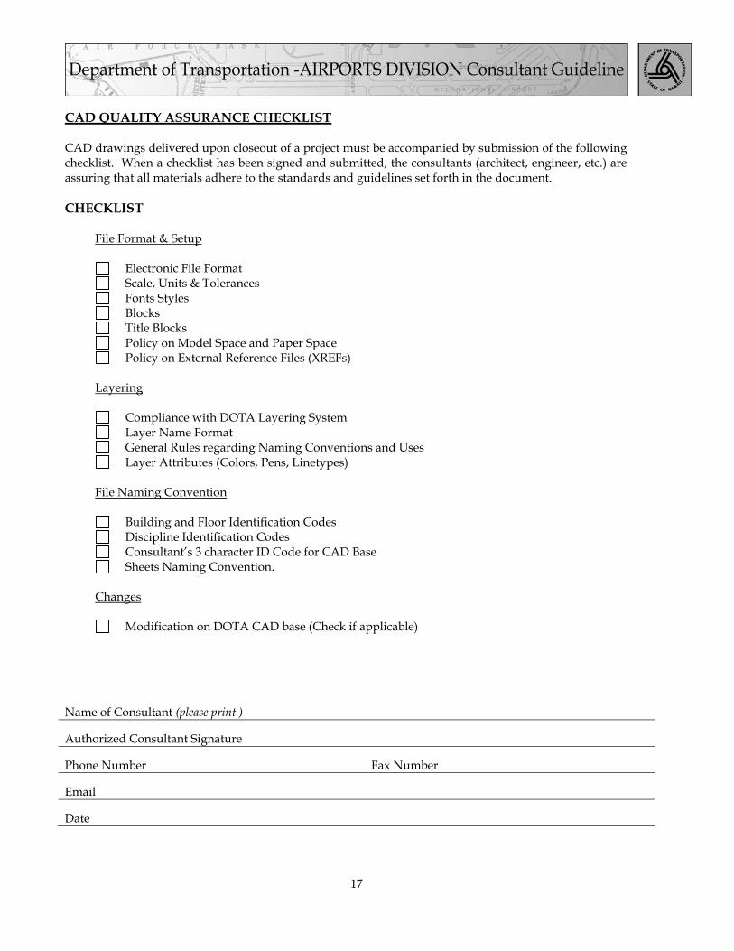
CAD QUALITY ASSURANCE CHECKLIST CAD drawings delivered upon closeout of a project must be accompanied by submission of the following checklist. When a checklist has been signed and submitted, the consultants (architect, engineer, etc.) are assuring that all materials adhere to the standards and guidelines set forth in the document. CHECKLIST File Format & Setup Electronic File Format Scale, Units & Tolerances Fonts Styles Blocks Title Blocks Policy on Model Space and Paper Space Policy on External Reference Files (XREFs) Layering Compliance with DOTA Layering System Layer Name Format General Rules regarding Naming Conventions and Uses Layer Attributes (Colors, Pens, Linetypes) File Naming Convention Building and Floor Identification Codes Discipline Identification Codes Consultant’s 3 character ID Code for CAD Base Sheets Naming Convention. Changes Modification on DOTA CAD base (Check if applicable)
Name of Consultant (please print )
Authorized Consultant Signature
Phone Number Fax Number
Date


19
APPENDIX A - SAMPLE OF TITLE SHEET AND STANDARD BORDER


25
APPENDIX B - SAMPLE OF TITLE SHEET BORDER WITH AS-BUILT INFORMATION


