dot/faa/ct-89/15 aircraft material fire · pdf filedot/faa/ct-89/15 faa technical center...
TRANSCRIPT

. ' ·'
DOT/FAA/CT-89/15
FAA Technical Center Atlantic City International Airport N.J. 08405
Aircraft Material Fire Test Handbook
--
September 1990
This document is available to the U.S. PJI!I/IT!:fi{;'(il" thrgugh the National Technical lnf()[.?]Ptfbn Servio@~<·PPringfield, Virgini~. ~j~e1···
0 U.S. Department of Transportation Federal Aviation Administration
NOTICE
This document is disseminated under the sponsorship of the U. S. Department of Transportation in the interest of information exchange. The United States Government assumes no liability for the contents or use thereof.
The United States Government does not endorse products or manufacturers. Trade or manufacturers' names appear herein solely because they are considered essential to the objective of this report.
/
T echnlcol ~•port Documentation Page
1. Report Ho. 2. Government Accuaion Ho. 3. Recipient' 1 Catalog Ho.
DOT/FAA/CT-89/15 4. Title onfl Subtitle
AIRCRAFT MATERIAL FIRE TEST HANDBOOK
S. Report l)ote
September 1990 6. Perfonning Orgoni lotion Coda
t----;;---:--~:-:----------------------------f I. Porfor111int Orgoni lotion Ropo•t No. 7. Author1al
9, Porformint Ortcr~i aotion Noma cr~cl Aclclroaa
Boeing Commercial Airplanes* P.O. Box 3707 Seattle, Washington 98124-2207
10. Wort. Unit No. (TRAIS)
II. Contract or Grant No.
DTFA03-87-C-00053 13. Typo of Report ond Period Covered
~~~--------~--~~----------------------------~ 12. Sponaorint Agency Noma ond Addroaa
U.S. Department of Transportation Federal Aviation Administration Technical Center
Final Report Oct. 1987 - Sept. 1990
14. Sponaoring Agency Coclo
Atlantic City International Airport, NJ 08405 ~------------------~------------------·--------~
ACD-240 15. Supplementary Notoa *Douglas Aircraft Company was a subcontractor.
FAA Contracting Officer's Technical Representative (COTR) was Constantine P. Sarkos
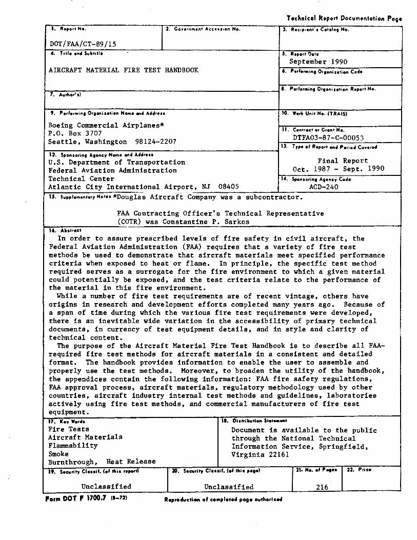
~1~,.~ ... ~~~-.t-,o-c~t----~-In order to assure prescribed levels of fire safety in civil aircraft, the
Federal Aviation Administration (FAA) requires that a variety of fire test methods be used to demonstrate that aircraft materials meet specified performance criteria when exposed to heat or flame. In principle, the specific test method required serves as a surrogate for the fire environment to which a given material could potentially be exposed, and the test criteria relate to the performance of the material in this fire environment.
While a number of fire test requirements are of recent vintag'e, others have origins in research and development efforts completed many years ago. Because of a span of time during which the various fire test requirements were developed, there is an inevitable wide variation in the accessibility of primary technical documents, in currency of test equipment details, and in style and clarity of technical content.
The purpose of the Aircraft Material Fire Test Handbook is to describe all FAArequired fire test methods for aircraft materials in a consistent and detailed format. The handbook provides information to enable the user to assemble and properly use the test methods. Moreover, to broaden the utility of the handbook, the appendices contain the following information: FAA fire safety regulations, FAA approval process, aircraft materials, regulatory methodology used by other countries, aircraft industry internal test methods and guidelines, laboratories actively using fire test methods, and commercial manufacturers of fire test equipment. 17. Kn Worll•
Fire Tests Aircraft Materials Flammability Smoke Burnthrough, Heat Release 19. Security Clouif. (of rhi• report)
Unclassified
Form DOT F 1700.7 ce-721
II. Dlatribvtlott Stoto1110ftl
Document is available to the public through the National Technical Information Service, Springfield, Virginia 22161
20. Security Cloulf. (of thi • poeol 21· No, of Pot•• 22. Price
Unclassified 216
Reproduction of complotod pogo outhorlaed
CONTENTS
Page LIST OF ILLUSTRATIONS ................................................................................................................................................. vii
LIST OF TABLES .................................................................................................................................................................. x
PREFACE ............................................................................................................................................................................... xi
1.0 VERTICAL BUNSEN BURNER TEST FOR CABIN AND CARGO COMPARTMENT MATERIALS ....................................................................................................................... 1-1 1.1 Scope ..................................................................................................................................................... 1-1 1.1. Definitions ............................................................................................................................................. 1-1 1.3 Test Apparatus ....................................................................................................................................... 1-1 1.4 Test Specimens ...................................................................................................................................... 1-3 1.5 Conditioning .......................................................................................................................................... 1-3 1.6 Procedure ............................................................................................................................................... 1-3 1.7 Report ..................................................................................................................................................... 1-4 1.8 Requirements ......................................................................................................................................... 1-4
2.0 45-DEG BUNSEN BURNER TEST FOR COMPARTMENT LINERS AND WASTE STOWAGE COMPARTMENT MATERIALS ················································:-·································2-1 2.1 Scope ..................................................................................................................................................... 2-1 2.2 Definitions ............................................................................................................................................. 2-1 2.3 Test Apparatus ....................................................................................................................................... 2-1 2.4 Test Specimens ...................................................................................................................................... 2-2 2.5 Conditioning .......................................................................................................................................... 2-3 2.6 Procedure ............................................................................................................................................... 2-3 2. 7 Report .................................................................................................................................................... 2-4 2.8 Requirements .......................................................................................................................................... 2-4
3.0 HORIZONTAL BUNSEN BURNER TEST FOR CABIN, CARGO COMPARTMENT AND MISCELLANEOUS MATERIALS ........................................................................................................... 3-1 3.1 Scope ...................................................................................................................................................... 3-1 3.2 Definitions ............................................................................................................................................. 3-1 3.3 Apparatus ............................................................................................................................................... 3-1 3.4 Test Specimens ...................................................................................................................................... 3-2 3.5 Conditioning .......................................................................................................................................... 3-3 3.6 Procedure ............................................................................................................................................... 3-3 3.7 Report .................................................................................................................................................... 3-4 3.8 Requirements ......................................................................................................................................... 3-4
4.0 60-DEG BUNSEN BURNER TEST FOR ELECTRIC WIRE .......................................................................... .4-1 4.1 Scope ..................................................................................................................................................... 4-1 4.2 Definitions ............................................................................................................................................. 4-1 4.3 Apparatus ............................................................................................................................................... 4-1 4.4 Test Specimens ...................................................................................................................................... 4-3 4.5 Conditioning .......................................................................................................................................... 4-3 4.6 Test Procedure ....................................................................................................................................... 4-3 4.7 Report .................................................................................................................................................... 4-4 4.8 Requirements ........... : ............................................................................................................................. 4-4
5.0 HEAT RELEASE RATE TEST FOR CABIN MATERIALS ............................................................................ 5-1 5.1 Scope ................................................................................................................................ , .................... 5-1 5.2 Definitions ............................................................................................................................................. 5-1 5.3 Test Apparatus ....................................................................................................................................... 5-1
iii
Page 5.4 Test Specimens ...................................................................................... , ............................................... 5-3 5.5 Conditioning .......................................................................................................................................... 5-4 5.6 Calibration ............................................................................................................................................. 5-4 5.7 Test Procedure ..................................................................................................................... , .................. 5-5 5.8 Report .................................................................................................................................................... 5-6 5.9 Requirements ................................. , ....................................................................................................... 5-6
6.0 SMOKE TEST FOR CABIN MATERIALS ....................................................................................................... 6-1 6.1 Scope ..................................................................................................................................................... 6-1 6.2 Definitions ............................................................................................................................................. 6-1 6. 3 Test Apparatus ....................................................................................................................................... 6-1 6.4 Test Specimen Selection and Preparation ............................................................................................. 6-5 6.5 Specimen Conditioning ......................................................................................................................... 6-6 6.6 Test Chamber Calibration ..................................................................................................................... 6-6 6. 7 Test Procedure ....................................................................................................................................... 6-7 6.8 Report .................................................................................................................................................... 6-8 6.9 Requirements ......................................................................................................................................... 6-8
7.0 OIL BURNER TEST FOR SEAT CUSHIONS .................................................................................................. 7-1 7.1 Scope ..................................................................................................................................................... 7-1 7.2 Definitions ............................................................................................................................................. 7-1 7.3 Apparatus ................................................................................................................................................ 7-1 7.4 Test Specimens ...................................................................................................................................... 7-3 7.5 Specimen Conditioning ......................................................................................................................... 7-4 7.6 Preparation of Apparatus ....................................................................................................................... 7-4 7.7 Calibration ............................................................................................................................................. 7-5 7.8 Test Procedure ....................................................................................................................................... 7-5 7.9 Report .................................................................................................................................................... 7-6 7.10 Requirements ......................................................................................................................................... 7-6
8.0 OIL BURNER TEST FOR CARGO LINERS .................................................................................................... 8-1 8.1 Scope ..................................................................................................................................................... 8-l 8.2 Definitions ............................................................................................................................................. 8-l 8.3 Apparatus ............................................................................................................................................... 8-1 8.4 Test Specimen(s) ................................................................................................................................... 8-2 8.5 Specimen Conditioning ......................................................................................................................... 8-2 8.6 Calibration ............................................................................................................................................. 8-3 8.7 Procedure ............................................................................................................................................... 8-3 8.8 Report .................................................................................................................................................... 8-4 8.9 Requirements ......................................................................................................................................... 8-4
9.0 RADIANT HEAT TESTING OF EVACUATION SLIDES, RAMPS, AND RAFTS ..................................... 9-1 9.1 Scope ..................................................................................................................................................... 9-l 9.2 Definitions ............................................................................................................................................. 9-1 9.3 Test Apparatus ....................................................................................................................................... 9-1 9.4 Test Specimens ...................................................................................................................................... 9-2 9.5 Conditioning .......................................................................................................................................... 9-2 9.6 Calibration ............................................................................................................................................. 9-2 9.7 Procedure ............................................................................................................................................... 9-2 9.8 Report .................................................................................................................................................... 9-3 9.9 Requirement .......................................................................................................................................... 9-3
10.0 FIRE CONTAINMENT TEST OF WASTE STOW AGE COMPARTMENTS .............................................. 10-1 10.1 Scope ................................................................................................................................................... 10-1 10.2 Definitions ........................................................................................................................................... 10-1
iv
Page 10.3 Test Apparatus/Equipment ................................................................................................................. 10-1 10.4 Test Unit .............................................................................................................................................. 10-2 10.5 Test Arrangements .............................................................................................................................. 10-3 10.6 Test Procedure ..................................................................................................................................... 10-4 10.7 Report ............................................................................................................................. -..................... 10-5 10.8 Requirements ....................................................................................................................................... 10-6
11.0 POWERPLANT HOSE ASSEMBLIES TEST ................................................................................................. 11-1 11.1 Scope ................................................................................................................................................... 11-1 11.2 Definitions ........................................................................................................................................... 11-1 11.3 Apparatus ............................................................................................................................................ 11-1 11.4 Test Specimens .................................................................................................................................... 11-3 11.5 Calibration ............................................................................................................................................ 11-3 11.6 Procedure .............................................................................................................................................. 11-4 11.7 Report ....................................... , .......................................................................................................... ll-5 11.8 Requirements ........................................................................................................................................ 11-5
12.0 POWERPLANT FIRE PENETRATION TEST ............................................................................................... 12-1 12.1 Scope ................................................................................................................................................... 12-1 12.2 Definitions ........................................................................................................................................... 12-1 12.3 Apparatus ............................................................................................................................................ 12-1 12.4 Test Specimens .................................................................................................................................... 12-2 12.5 Conditioning ........................................................................................................................................ 12-2 12.6 Calibration ..................................................................................................... : ..................................... 12-3 12.7 Procedure .......................... , .................................................................................................................. 12-4 12.8 Report .................................................................................................................................................. l2-4 12.9 Requirements ....................................................................................................................................... 12-4
13.0 TEST FOR ELECTRICAL CONNECTORS USED IN FIREW ALLS ............................................................ 13-1 13.1 Scope ................................................................................................................................................... 13-1 13.2 Definitions ........................................................................................................................................... 13-1 13.3 Apparatus ............................................................................................................................................ 13-1 13.4 Test Specimens .................................................................................................................................... 13-2 13.5 Procedure ............................................................................................................................................. l3-2 13.6 Report .................................................................................................................................................. l3-3 13.7 Requirements ....................................................................................................................................... 13-3
14.0 TEST FOR ELECTRICAL WIRE USED IN DESIGN A TED FIRE ZONES .................................................. 14-1 14.1 Scope ................................................................................................................................................... 14-1 14.2 Definitions ........................................................................................................................................... 14-1 14.3 Apparatus ............................................................................................................................................ 14-1 14.4 Test Specimens .................................................................................................................................... 14-2 14.5 Conditioning/Preparation of Test Specimens ..................................................................................... 14-3 14.6 Calibration ........................................................................................................................................... 14-3
14.7 Procedure············································································································'································ 14-3 14.8 Report .................................................................................................................................................. 14-4 14.9 Requirements ....................................................................................................................................... 14-4
APPENDIX A: FAA REGULATIONS ............................................................................................................................... A-1 1.1 A Brief History of Federal Agencies Regulating Aviation .................................................................. A-1 1.2 Organization of the FAA ...................................................................................................................... A-2 1.3 Enabling Legislation and Procedures for the FAA ............................................................................... A-4 1.4 Documentary Sources for Flammability Requirements ....................................................................... A-8
v
Page APPENDIX B: THE APPROVAL PROCESS .................................................................................................................... B-1
1.1 Introduction ............................................................................................................................................ B-1 1.2 Approval Steps-Manufacturers ........................................................................................................... B-1 1.3 Approval Steps--Operators .................................................................................................................. B-7
APPENDIX C: MATERIALS USED IN AIRCRAFT ........................................................................................................ C-1 1.1 Introduction ........................................................................................................................................... C-1 1.2 Aircraft Seats ........................................................................................................................................ C-1 1.3 Insulating Materials .............................................................................................................................. C-1 1.4 Interior Panel Structures ....................................................................................................................... C-2 1.5 Floor Coverings .................................................................................................................................... C-3 1.6 Draperies ............................................................................................................................................... C-3 1.7 Nonmetallic Air Ducting ...................................................................................................................... C-3 1.8 Linings (Nonpanel) ............................................................................................................................... C-4 1.9 Electrical Components .......................................................................................................................... C-4 1.10 Firewalls ............................................................................................................................................... C-5 1.11 Windows ..................................................................................................................................... , ......... C-5 1.12 Small Parts ............................................................................................................................................ C-5
ADDENDIX D: REGULATORY METHODOLOGY USED BY OTHER COUNTRIES ............................................... D-1 1.1 Introduction ........................................................................................................................................... D-1 1.2 Foreign Airworthiness Authorities and Regulations ............................................................................ D-1 1.3 Regulations Covering Foreign Air Carriers ......................................................................................... D-2 1.4 Certification of Foreign-Manufactured Aircraft ................................................................................... D-3
APPENDIX E: AIRCRAFT INDUSTRIES INTERNAL TEST METHODS AND GUIDELINES .................................. E-1
APPENDIX F: LABORATORIES ACTIVELY USING FIRE TEST PROCEDURES .................................................... F-1
APPENDIX G: COMMERCIAL MANUFACTURERS OF FIRE TEST EQUIPMENT ................................................... G-1
vi
Figure
1-1
1-2
1-3
1-4
1-5
1-6
2-1
2-2
2-3
2-4
2-5
2-6
3-1
3-2
3-3
3-4
3-5
3-6
4-1
4-2
5-la
5-lb
5-2
5-3
5-4
5-5a
5-5b
5-6
6-1
6-2
6-3
6-4
6-5
LIST OF ILLUSTRATIONS
Page
Sketch of Vertical Bunsen Burner Test Cabinet .................................................................................................. 1-5
Front and Side View of Vertical Bunsen Burner Test Cabinet ........................................................................... 1-6
Vertical Bunsen Burner Test Specimen Holder ................................................................................................... 1-7
Burner Plumbing/Burner Flame Height Indicator ............................................................................................... 1-8
Flame Position on Vertical Specimens Less than 3/4 in Thick ........................................................................... 1-9
Flame Position on Vertical Specimens Greater than 3/4 in Thick ...................................................................... l-10
Sketch of 30-Second 45-Degree Bunsen Burner Test Cabinet ........................................................................... 2-5
Front and Top View of 30-Second 45-Degree Bunsen Burner Test Cabinet ..................................................... 2-6
Side Views of 30-Second 45-Degree Bunsen Burner Test Cabinet .................................................................... 2-7
30-Second 45-Degree Bunsen Burner Test Specimen Frame and Stand ............................................................. 2-8
Burner Plumbing/Burner Flame Height Indicator ............................................................................................... 2-9
Flame Position on 30-Second 45-Degree Bunsen Burner Test Specimen ........................................................ 2-10
Sketch of Horizontal Bunsen Burner Test Cabinet.. ............................................................................................ 3-5
Front and Top View of Horizontal Bunsen Burner Test Cabinet ........................................................................ 3-6
Side Views of Horizontal Bunsen Burner Test Cabinet ...................................................................................... 3-7
Horizontal Bunsen Burner Test Specimen Holder .............................................................................................. 3-8
Burner Plumbing/Burner Flame Height Indicator ............................................................................................... 3-9
Gage Line Positions on Horizontal Bunsen Burner Test Specimen .................................................................. 3-10
60-Degree Electrical Wire Bunsen Burner Test Setup ........................................................................................ 4-5
Burner Plumbing and Burner Flame Height Indicator ........................................................................................ 4-6
Rate of Heat Release Apparatus .......................................................................................................................... 5-7
Rate of Heat Release Apparatus .......................................................................................................................... 5-8
Side View--Globar Radiant Heat Panel .............................................................................................................. 5-9
Heat Release Specimen Holder, Mounting Bracket, and Drip Pan ................................................................... 5-l 0
Lower Pilot Burner Igniter Schematic ............................................................................................................... 5-11
Upper Pilot Burner-Three Hole Burner .......................................................................................................... 5-12
Upper Pilot Burner-Fourteen Hole Burner ...................................................................................................... 5-12
Calibration Burner ............................................................................................................................................. 5-13
NBS Smoke Density Chamber ............................................................................................................................ 6-9
Furnace Section ................................................................................................................................................. 6-10
Heater Orientation ............................................................................................................................................. 6-10
Alignment of Holder and Burner ....................................................................................................................... 6-11
Flame Size ......................................................................................................................................................... 6-12
vii
Figure Page
6-6 Details of Specimen Holder ............................................................................................................................... 6-13
6-7 Typical Furnace Support ..................................................................................................................... _. ............... 6-14
6-8 Photometer Detail .............................................................................................................................................. 6-15
6-9 Photometer Location .......................................................................................................................................... 6-16
7-1 Front, Side, and Top Views of Seat Oil Burner Specimen Frame ....................................................................... 7-7
7-2 Top and Side View of Specimen Setup in Test Frame ........................................................................................ 7-8
7-3 Burner Cone Details ............................................................................................................................................ 7-9
7-4 Top and Side Views of Calorimeter Bracket ..................................................................................................... 7-10
7-5 Top and Side Views of Thermocouple Rake Bracket ....................................................................................... 7-11
7-6 Example of Production Seat Configuration and Test Specimen Set to Substantiate Production Seat Bottom Cushion .................................................................................................. 7-12
7-7 Specimen Set to Substantiate Production Seat Bottom and Specimen Set to Substantiate Production Seat Back .................................................................................................................... 7-13
7-8 Example of Production Seat Configuration Using Two Dress Cover Materials and Test Specimen Set to Substantiate Dress Cover Combination .......................................................................... 7-14
8-1 Test Apparatus for Horizonal and Vertical Mounting for Cargo Liner Oil Burner Testing ................................ 8-5
8-2 Cargo Liner Test Specimen Frame ...................................................................................................................... 8-6
8-3 Cargo Liner Test Specimen Retaining Frame ..................................................................................................... 8-7
8-4 Burner Cone Details ............................................................................................................................................ 8-8
8-5 Top and Side Views of Calorimeter Bracket ....................................................................................................... 8-9
8-6 Top and Side Views of Thermocouple Rake Bracket ....................................................................................... 8-10
9-1 Evacuation Slide Material Test Apparatus-Front View .................................................................................... 9-4
9-2 Evacuation Slide Material Test Apparatus-Side View ..................................................................................... 9-5
9-3 Evacuation Slide Material Test Apparatus-Top View ...................................................................................... 9-6
9-4 Furnace Details .................................................................................................................................................... 9-7
10-1 Sample Fire Containment Temperature versus Time Plot.. ............................................................................... 10-8
11-1 Burner Extension Funnel ................................................................................................................................. 11-10
11-2 Air Tube Reducing Cone ................................................................................................................................. 11-11
11-3 Hose Assemblies Test Setup ............................................................................................................................ 11-12
11-4 Burner Calibration Standardization Apparatus ................................................................................................ 11-13
11-5 BTU Heat Transfer Device .............................................................................................................................. 11-14
11-6 BTU Heat Transfer Device-Reducer ............................................................................................................ 11-15
11-7 BTU Heat Transfer Device-Inlet Tube .......................................................................................................... 11-16
11-8 BTU Heat Transfer Device-Outlet Tube ...................................................................................................... 11-17
11-9 BTU Heat Transfer Device-Thermometer Mounting .................................................................................... 11-18
11-10 BTU Heat Transfer Device-Test Specimen .................................................................................................. 11-19
viii
Figure Page
12-1 Firewall Penetration Test Setup ......................................................................................................................... 12-5
13-1 Firewall Connector Test Setup .......................................................................................................................... 13-6
13-2 Firewall Connector Fixture Assembly ............................................................................................................... 13-7
13-3 Firewall Connector Fixture Details ................................................................................................................... 13-8
13-4 Connector Electrical Integrity Connection Diagram ......................................................................................... 13-9
14-1 Firezone Electrical Wire Test Setup ................................................................................................................... 14-6
14-2 Burner Details ..................................................................................................................................................... 14-7
14-3 Thermocouple Details ........................................................................................................................................ 14-8
14-4 Firezone Electrical Wire Test Setup-Top View .............................................................................................. 14-8
14-5 Electrical Connections ....................................................................................................................................... 14-9
B-1 FAA Form 8110-3 (Statement of Compliance) .................................................................................................. B-8
B-2 Federal Aviation Administration Type Certificate ............................................................................................. B-9
B-3 Statement of Conformity ................................................................................................................................... B-1 0
B-4 Authorized Release Certificate Approval Tag .................................................................................................. B-11
B-5 Standard Airworthiness Certificate ................................................................................................................... B-12
C-1 Typical Seat Installation ...................................................................................................................................... C-6
C-2 Typical Panel Installation ..................................................................................................................................... C-7
C-3 Typical Main Cabin ............................................................................................................................................ C-8
C-4 Typical High Bypass Engine ................................................................................................................................ C-9
IX
LIST OF TABLES
Table Page
10-1 Meal Box Test Arrangements ............................................................................................................................ 10-7
11-1 Test Burner Information .................................................................................................................................... 11-6
11-2 Circulating Oil Pressure and Flow Rate .......................................................... " ................................................ 11-9
13-1 Firewall Connector Test Current ....................................................................................................................... 13-5
14-1 Specimen Immersion Information ..................................................................................................................... 14-5
D-1 Summary of Bilateral Airworthiness Agreements .............................................................................................. D-5
E-1 Industry Test Documentation ................................................................................................. ; ............................ E-2
X
Preface
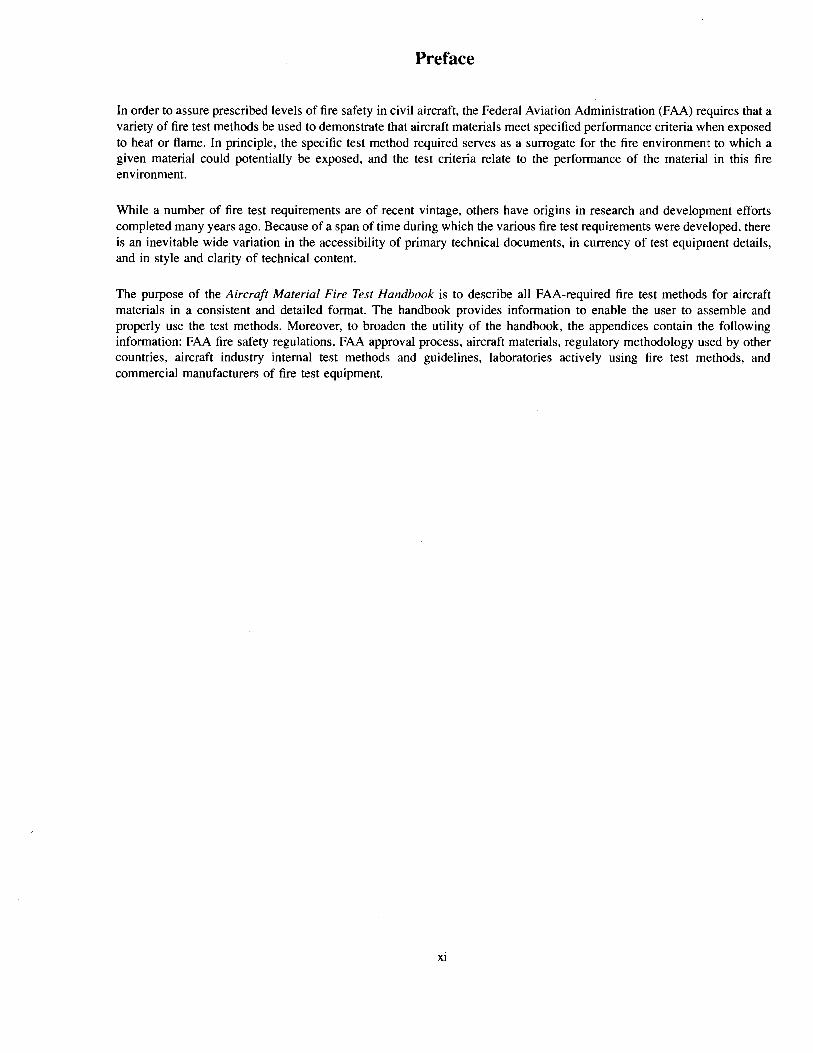
In order to assure prescribed levels of fire safety in civil aircraft, the Federal Aviation Administration (FAA) requires that a variety of fire test methods be used to demonstrate that aircraft materials meet specified performance criteria when exposed to heat or flame. In principle, the specific test method required serves as a surrogate for the fire environment to which a given material could potentially be exposed, and the test criteria relate to the performance of the material in this fire environment.
While a number of fire test requirements are of recent vintage, others have origins in research and development efforts completed many years ago. Because of a span of time during which the various fire test requirements were developed, there is an inevitable wide variation in the accessibility of primary technical documents, in currency of test equipment details, and in style and clarity of technical content.
The purpose of the Aircraft Material Fire Test Handbook is to describe all FAA-required fire test methods for aircraft materials in a consistent and detailed format. The handbook provides information to enable the user to assemble and properly use the test methods. Moreover, to broaden the utility of the handbook, the appendices contain the following information: FAA fire safety regulations, FAA approval process, aircraft materials, regulatory methodology used by other countries, aircraft industry internal test methods and guidelines, laboratories actively using fire test methods, and commercial manufacturers of fire test equipment.
xi
This page intentionally left blank
XII
Chapter 1 Vertical Bunsen Burner Test for Cabin and Cargo Compartment Materials
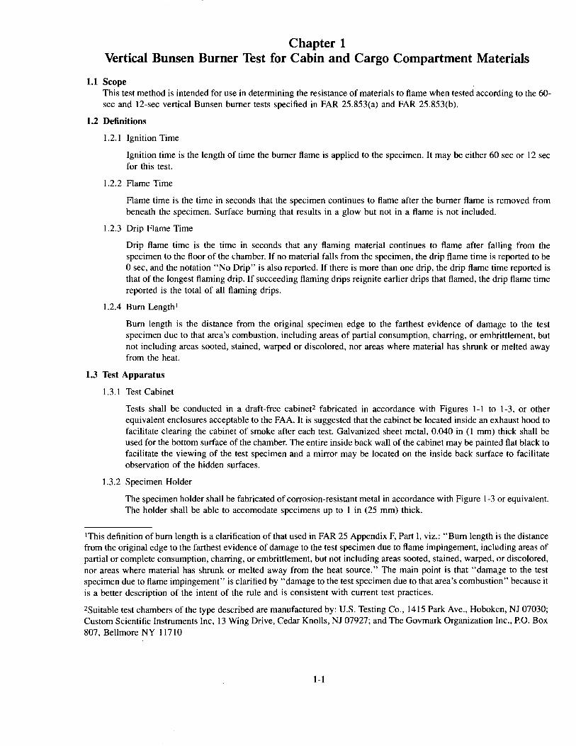
1.1 Scope This test method is intended for use in determining the resistance of materials to flame when tested according to the 60-sec and 12-sec vertical Bunsen burner tests specified in FAR 25.853(a) and FAR 25.853(b).
1.2 Definitions
1.2.1 Ignition Time
Ignition time is the length of time the burner flame is applied to the specimen. It may be either 60 sec or 12 sec for this test.
1.2.2 Flame Time
Flame time is the time in seconds that the specimen continues to flame after the burner flame is removed from beneath the specimen. Surface burning that results in a glow but not in a flame is not included.
1.2.3 Drip Flame Time
Drip flame time is the time in seconds that any flaming material continues to flame after falling from the specimen to the floor of the chamber. If no material falls from the specimen, the drip flame time is reported to be 0 sec, and the notation "No Drip" is also reported. If there is more than one drip, the drip flame time reported is that of the longest flaming drip. If succeeding flaming drips reignite earlier drips that flamed, the drip flame time reported is the total of all flaming drips.
1.2.4 Bum Length I
Bum length is the distance from the original specimen edge to the farthest evidence of damage to the test specimen due to that area's combustion, including areas of partial consumption, charring, or embrittlement, but not including areas sooted, stained, warped or discolored, nor areas where material has shrunk or melted away from the heat.
1.3 Test Apparatus
1.3.1 Test Cabinet
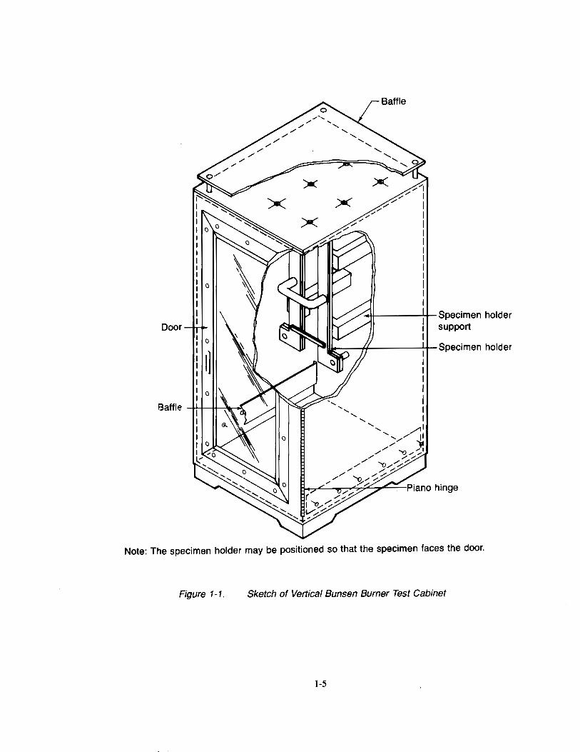
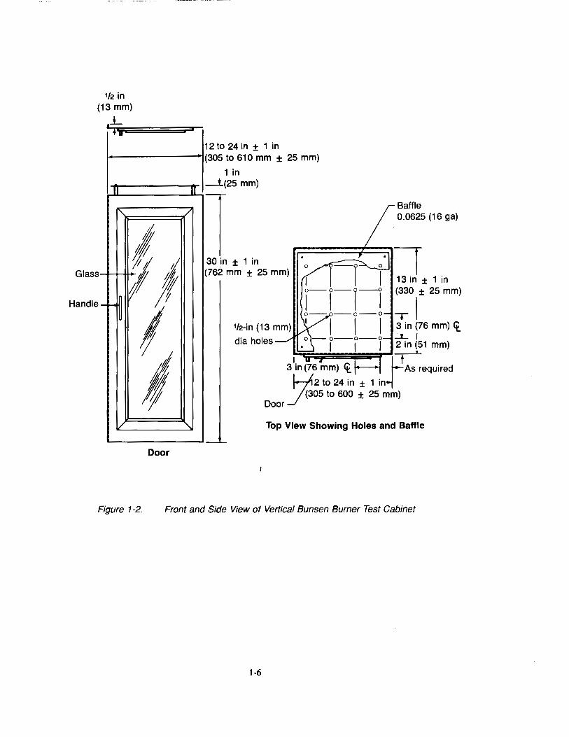
Tests shall be conducted in a draft-free cabinet2 fabricated in accordance with Figures 1-1 to 1-3, or other equivalent enclosures acceptable to the FAA. It is suggested that the cabinet be located inside an exhaust hood to facilitate clearing the cabinet of smoke after each test. Galvanized sheet metal, 0.040 in (1 mm) thick shall be used for the bottom surface of the chamber. The entire inside back wall of the cabinet may be painted flat black to facilitate the viewing of the test specimen and a mirror may be located on the inside back surface to facilitate observation of the hidden surfaces.
1.3.2 Specimen Holder
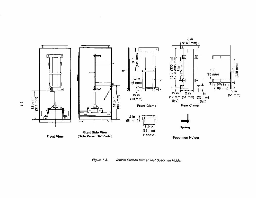
The specimen holder shall be fabricated of corrosion-resistant metal in accordance with Figure l-3 or equivalent. The holder shall be able to accomodate specimens up to 1 in (25 mm) thick.
1This definition of bum length is a clarification of that used in FAR 25 Appendix F, Part I, viz.: "Bum length is the distance from the original edge to the farthest evidence of damage to the test specimen due to flame impingement, including areas of partial or complete consumption, charring, or embrittlement, but not including areas sooted, stained, warped, or discolored, nor areas where material has shrunk or melted away from the heat source." The main point is that "damage to the test specimen due to flame impingement" is clarified by "damage to the test specimen due to that area's combustion" because it is a better description of the intent of the rule and is consistent with current test practices.
zsuitable test chambers of the type described are manufactured by: U.S. Testing Co., 1415 Park Ave., Hoboken, NJ 07030; Custom Scientific Instruments Inc, 13 Wing Drive, Cedar Knolls, NJ 07927; and The Govmark Organization Inc., P.O. Box 807, Bellmore NY 11710
1-1
1.3.3 Burner
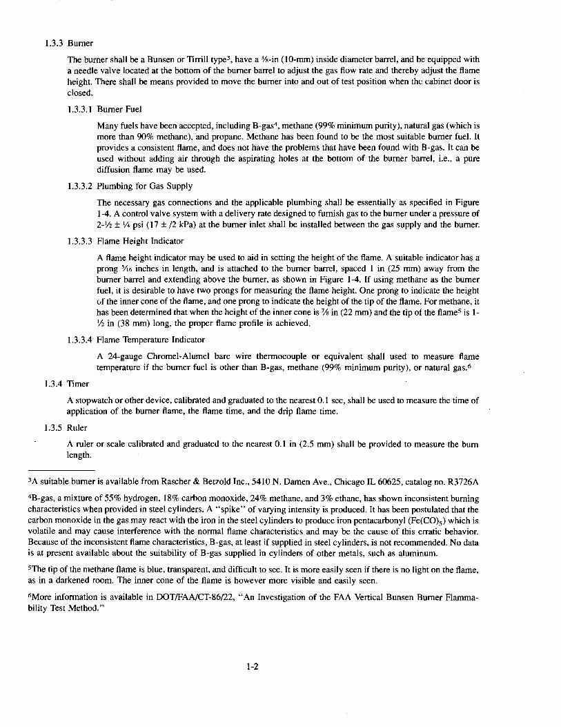
The burner shall be a Bunsen or Tirrill type3 , have a %-in (10-mm) inside diameter barrel, and be equipped with a needle valve located at the bottom of the burner barrel to adjust the gas flow rate and thereby adjust the flame height. There shall be means provided to move the burner into and out of test position when the: cabinet door is closed.
1.3.3.1 Burner Fuel
Many fuels have been accepted, including B-gas4, methane (99% minimum purity), natural gas (which is more than 90% methane), and propane. Methane has been found to be the most suitable burner fuel. It provides a consistent flame, and does not have the problems that have been found with 8-gas. It can be used without adding air through the aspirating holes at the bottom of the burner barrel, i.e., a pure diffusion flame may be used.
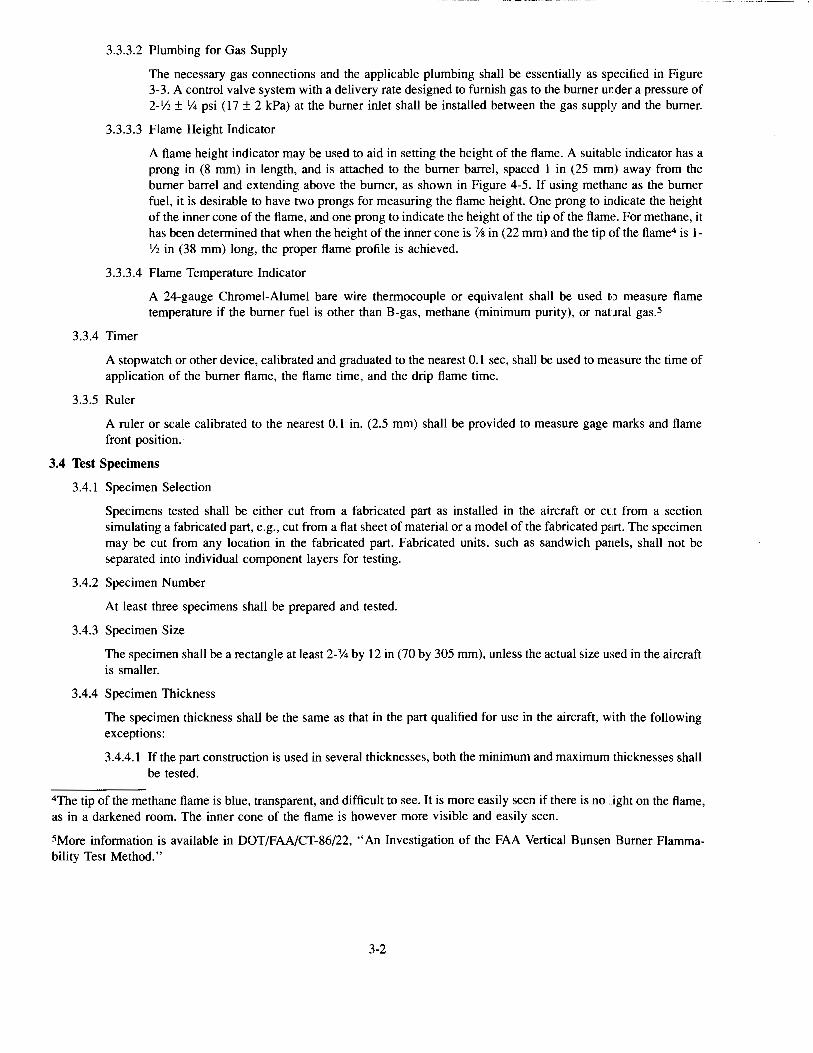
1.3.3.2 Plumbing for Gas Supply
The necessary gas connections and the applicable plumbing shall be essentially as specified in Figure l-4. A control valve system with a delivery rate designed to furnish gas to the burner under a pressure of 2-V2 ± 1/4 psi (17 ± /2 kPa) at the burner inlet shall be installed between the gas supply and the burner.
1.3.3.3 Flame Height Indicator
A flame height indicator may be used to aid in setting the height of the flame. A suitable indicator has a prong 5!\6 inches in length, and is attached to the burner barrel, spaced I in (25 mm) away from the burner barrel and extending above the burner, as shown in Figure 1-4. If using methane as the burner fuel, it is desirable to have two prongs for measuring the flame height. One prong to indicate the height vf the inner cone of the flame, and one prong to indicate the height of the tip of the flame. For methane, it has been determined that when the height of the inner cone is 7/s in (22 mm) and the tip of the flames is llf2 in (38 mm) long, the proper flame profile is achieved.
1.3.3.4 Flame Temperature Indicator
1.3.4 Timer
A 24-gauge Chromel-Alumel bare wire thermocouple or equivalent shall used to measure flame temperature if the burner fuel is other than B-gas, methane (99% minimum purity), or natural gas.6
A stopwatch or other device, calibrated and graduated to the nearest 0.1 sec, shall be used to measure the time of application of the burner flame, the flame time, and the drip flame time.
1.3.5 Ruler
A ruler or scale calibrated and graduated to the nearest 0.1 in (2.5 mm) shall be provided to measure the bum length.
3A suitable burner is available from Rascher & Betzold Inc., 5410 N. Damen Ave., Chicago IL 60625, catalog no. R3726A
4B-gas, a mixture of 55% hydrogen, 18% carbon monoxide, 24% methane, and 3% ethane, has shown inconsistent burning characteristics when provided in steel cylinders. A "spike" of varying intensity is produced. It has been postulated that the carbon monoxide in the gas may react with the iron in the steel cylinders to produce iron pentacarbonyl (Fe(C0)5 ) which is volatile and may cause interference with the normal flame characteristics and may be the cause of this erratic behavior. Because of the inconsistent flame characteristics, B-gas, at least if supplied in steel cylinders, is not recommended. No data is at present available about the suitability of B-gas supplied in cylinders of other metals, such as aluminum.
5The tip of the methane flame is blue, transparent, and difficult to see. It is more easily seen if there is no light on the flame, as in a darkened room. The inner cone of the flame is however more visible and easily seen.
6More information is available in DOT/FAA/CT-86/22, "An Investigation of the FAA Vertical Bunsen Burner Flammability Test Method."
1-2
1.4 Test Specimens
1.4.1 Specimen Selection
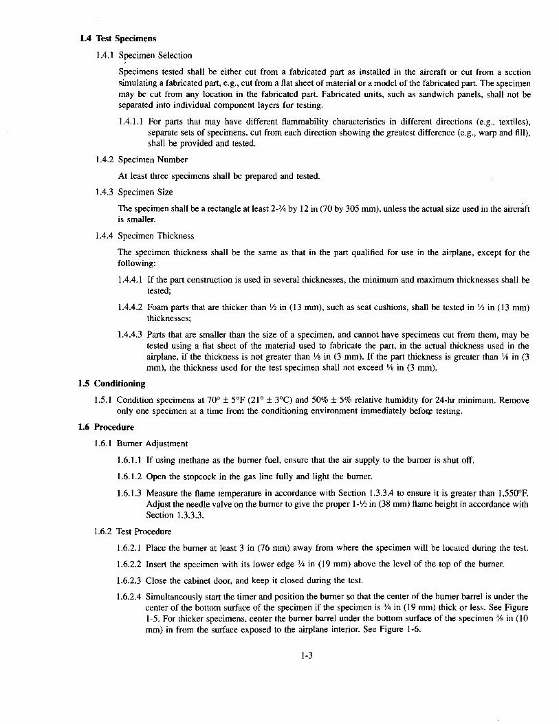
Specimens tested shall be either cut from a fabricated part as installed in the aircraft or cut from a section simulating a fabricated part, e.g., cut from a flat sheet of material or a model of the fabricated part. The specimen may be cut from any location in the fabricated part. Fabricated units, such as sandwich panels, shall not be separated into individual component layers for testing.
1.4.1.1 For parts that may have different flammability characteristics in different directions (e.g., textiles), separate sets of specimens, cut from each direction showing the greatest difference (e.g., warp and fill), shall be provided and tested.
1.4.2 Specimen Number
At least three specimens shall be prepared and tested.
1.4.3 Specimen Size
The specimen shall be a rectangle at least 2-% by 12 in (70 by 305 mm), unless the actual size used in the aircraft is smaller.
1.4.4 Specimen Thickness
The specimen thickness shall be the same as that in the part qualified for use in the airplane, except for the following:
1.4.4.1 If the part construction is used in several thicknesses, the minimum and maximum thicknesses shall be tested;
1.4.4.2 Foam parts that are thicker than V2 in (13 mm), such as seat cushions, shall be tested in 1f2 in (13 mm) thicknesses;
1.4.4.3 Parts that are smaller than the size of a specimen, and cannot have specimens cut from them, may be tested using a flat sheet of the material used to fabricate the part, in the actual thickness used in the airplane, if the thickness is not greater than 'Is in (3 mm). If the part thickness is greater than 1/s in (3 mm), the thickness used for the test specimen shall not exceed 'Is in (3 mm).
1.5 Conditioning
1.5.1 Condition specimens at 70° ± 5°F (21° ± 3°C) and 50%± 5% relative humidity for 24-hr minimum. Remove only one specimen at a time from the conditioning environment immediately befo~ testing.
1.6 Procedure
1.6.1 Burner Adjustment
1.6.1.1 If using methane as the burner fuel, ensure that the air supply to the burner is shut off.
1.6.1.2 Open the stopcock in the gas line fully and light the burner.
1.6.1.3 Measure the flame temperature in accordance with Section 1.3.3.4 to ensure it is greater than 1,550°F. Adjust the needle valve on the burner to give the proper 1-lf2 in (38 mm) flame height in accordance with Section 1.3.3.3.
1.6.2 Test Procedure
1.6.2.1 Place the burner at least 3 in (76 mm) away from where the specimen will be located during the test.
1.6.2.2 Insert the specimen with its lower edge % in (19 mm) above the level of the top of the burner.
1.6.2.3 Close the cabinet door, and keep it closed during the test.
1.6.2.4 Simultaneously start the timer and position the burner so that the center of the burner barrel is under the center of the bottom surface of the specimen if the specimen is % in (19 mm) thick or less. See Figure 1-5. For thicker specimens, center the burner barrel under the bottom surface of the specimen 3fs in (10 mm) in from the surface exposed to the airplane interior. See Figure 1-6.
1-3
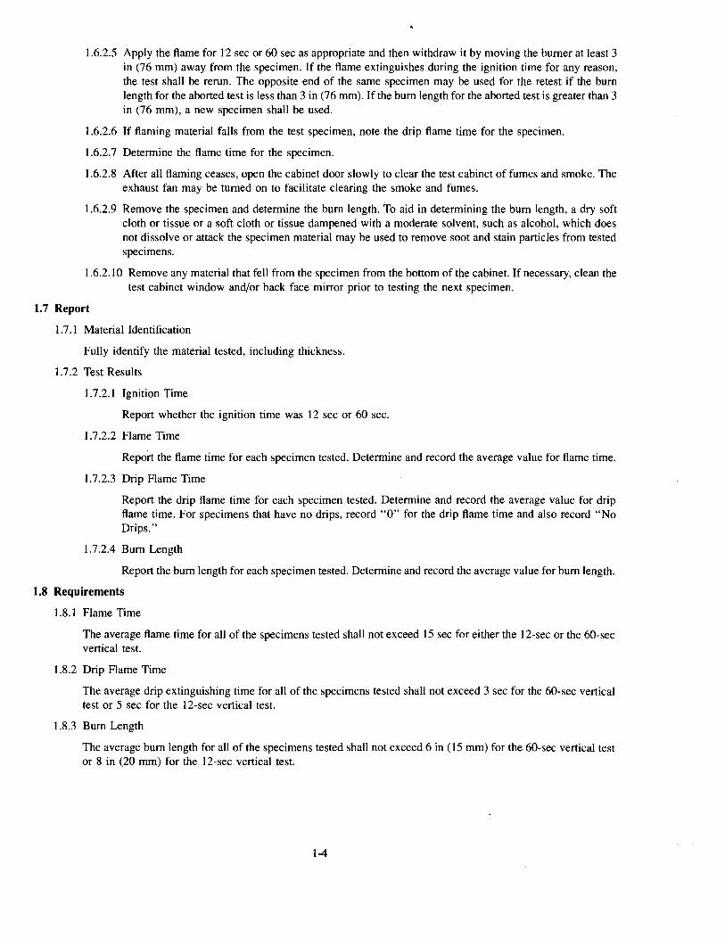
1.6.2.5 Apply the flame for 12 sec or 60 sec as appropriate and then withdraw it by moving the burner at least 3 in (76 mm) away from the specimen. If the flame extinguishes during the ignition time for any reason, the test shall be rerun. The opposite end of the same specimen may be used for the retest if the bum length for the aborted test is less than 3 in (76 mm). If the bum length for the aborted test is greater than 3 in (76 mm), a new specimen shall be used.
I.6.2.6 If flaming material falls from the test specimen, note the drip flame time for the specimen.
I.6.2. 7 Determine the flame time for the specimen.
I.6.2.8 After all flaming ceases, open the cabinet door slowly to clear the test cabinet of fumes and smoke. The exhaust fan may be turned on to facilitate clearing the smoke and fumes.
I.6.2.9 Remove the specimen and determine the bum length. To aid in determining the bum length, a dry soft cloth or tissue or a soft cloth or tissue dampened with a moderate solvent, such as alcohol, which does not dissolve or attack the specimen material may be used to remove soot and stain particles from tested specimens.
1.6.2.1 0 Remove any material that fell from the specimen from the bottom of the cabinet. If necessary, clean the test cabinet window and/or back face mirror prior to testing the next specimen.
1.7 Report
1. 7 .I Material Identification
Fully identify the material tested, including thickness.
1.7.2 Test Results
I. 7 .2.I Ignition Time
Report whether the ignition time was 12 sec or 60 sec.
1.7.2.2 Flame Time
Report the flame time for each specimen tested. Determine and record the average value for flame time.
1.7.2.3 Drip Flame Time
Report the drip flame time for each specimen tested. Determine and record the average value for drip flame time. For specimens that have no drips, record "0" for the drip flame time and also record "No Drips."
1.7.2.4 Bum Length
Report the bum length for each specimen tested. Determine and record the average value for bum length.
1.8 Requirements
1.8.1 Flame Time
The average flame time for all of the specimens tested shall not exceed I5 sec for either the 12-sec or the 60-sec vertical test.
1.8.2 Drip Flame Time
The average drip extinguishing time for all of the specimens tested shall not exceed 3 sec for the 60-sec vertical test or 5 sec for the 12-sec vertical test.
1.8.3 Bum Length
The average bum length for all of the specimens tested shall not exceed 6 in (15 mm) for the 60-sec vertical test or 8 in (20 mm) for the 12-sec vertical test.
1-4
·~-----l+- Specimen holder Door support
._--1-f------.L..I- Specimen holder
Note: The specimen holder may be positioned so that the specimen faces the door.
Figure 1-1. Sketch of Vertical Bunsen Burner Test Cabinet
1-5
1/2 in (13 mm)
.L I h
II
1'\
Glass t
Handle ~ fj ~ 1 - f-t
I If II
v
Door
i
12 to 24 in ± 1 in (305 to 610 mm ± 25 mm)
1 in ---L(
II ,-, 25 mm)
/ Baffle 0.0625 (16 ga)
30 in ± 1 in (762 mm ± 25 mm)
dia holes
" Top View Showing Holes and Baffle
'-'--
Figure 1-2. Front and Side View of Vertical Bunsen Burner Test Cabinet
1-6
-I -..1
T·-c:E ·- E ~ ,.... ..... C\1..-..... ~
I I' _1_r · I v I
1
I _ I 1
Front View Right Side View
(Side Panel Removed)
Figure 1-3.
Tlo 0
-E -~ E com
"'¢ ..... -_L_
Front Clamp
2in IJ~ (51 mm) til td
13v2 in• I
(88 mm) Handle
6 in ~(149 mm)-1 rrl-on I
-- --rH}, EE .,-lt~-
0
E E OLO E Moc:E (') (') ·--r--oo¢ c: c: 1"-·- ·- ,.... (')C\J I ..... ..... • ll;'
4=-" JJ
~ •I• .. [ 1/2 in 2 in
..1.. £j_ II +
1 in (12 mm) (51 mm)
(typ) (25 mm)
(typ) Rear Clamp
-l Spring
Specimen Holder
Vertical Bunsen Burner Test Specimen Holder
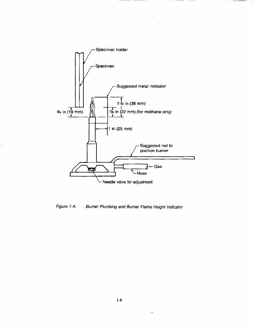
Figure 1-4.
Specimen holder
Specimen
Suggested metal indicator
t 1112 in (38 mm)
---r I 7fa in (22 mm) (for methane only)
t t
.__~ 1 in (25 mm)
Suggested rod to position burner
Needle valve for adjustment
Burner Plumbing and Burner Flame Height Indicator
1-8
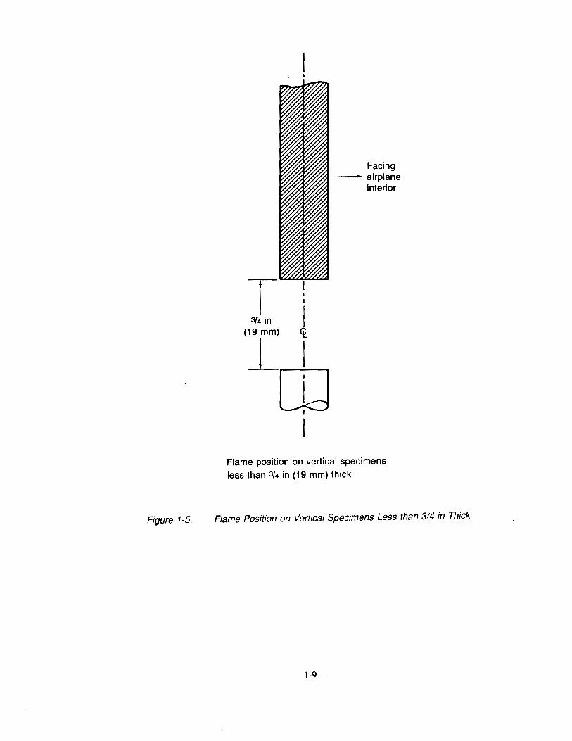
Figure 1-5.
T 3/4 in I
(19 mm) <t_
j_J rn I
I
Facing -airplane
interior
Flame position on vertical specimens less than 3/4 in (19 mm) thick
Flame Position on Vertical Specimens Less than 314 in Thick
1-9
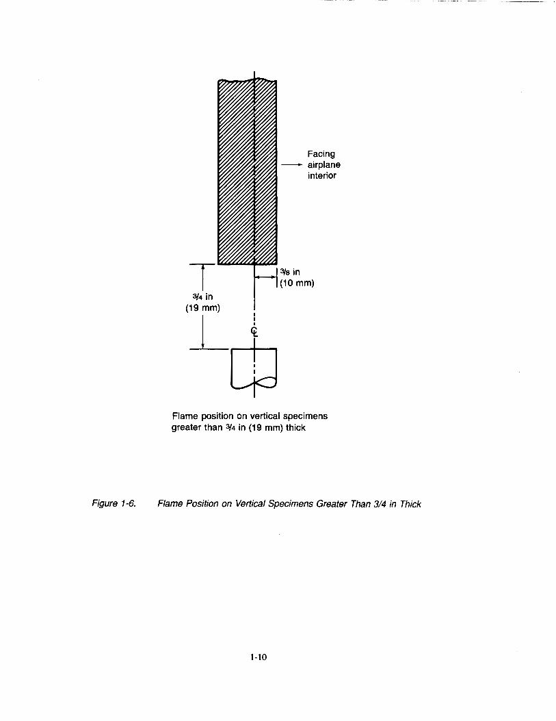
Figure 1-6.
3/4 in (19 mm)
I
j_~<tl-:......,
Facing --- airplane
interior
3/s in (10 mm)
Flame position on vertical specimens greater than 3/4 in (19 mm) thick
Flame Position on Vertical Specimens Greater Than 314 in Thick
1-10
Chapter 2 45-Deg Bunsen Burner Test for Cargo Compartment Liners and Waste Stowage
Compartment Materials
2.1 Scope
2.1.1 This test method is intended for use in determining the resistance of materials to flame penetration and to flame and glow propagation when tested according to the 30-sec 45-deg Bunsen burner test specified in FAR 25.855(a-1)(2).
2.2 Definitions
2.2.1 Ignition Time
Ignition time is the length of time the burner flame is applied to the specimen. For this test, the ignition time is 30 sec.
2.2.2 Flame Time
Flame time is the time in seconds that the specimen continues to flame after the burner flame is removed from under the specimen.
2.2.3 Glow Time
Glow time is the length of time in seconds that the specimen continues to glow, without flaming combustion, after any flaming combustion ceases following the removal of the ignition flame.
2.2.4 Flame Penetration
Flame penetration occurs if the Bunsen burner flame penetrates (passes through) the test specimen through a hole or crack in the specimen that forms during the test ignition time. Flaming combustion on the top of the specimen that results from auto ignition is not considered flame penetration in this test.
2.3 Test Apparatus
2.3.1 Test Cabinet
Tests shall be conducted in a draft-free cabinet1 as shown in Figures 2-1 to 2-3 or other equivalent enclosures acceptable to the FAA. It is suggested that the cabinet be located inside an exhaust hood to facilitate clearing the cabinet of smoke after each test. Galvanized sheet metal, 0.040 in (1 mm) thick shall be used for the bottom surface of the chamber. The entire inside back wall of the cabinet may be painted flat black to facilitate the viewing of the test specimen and a mirror may be located on the inside back surface to facilitate observation of hidden surfaces.
2.3.2 Specimen Holder
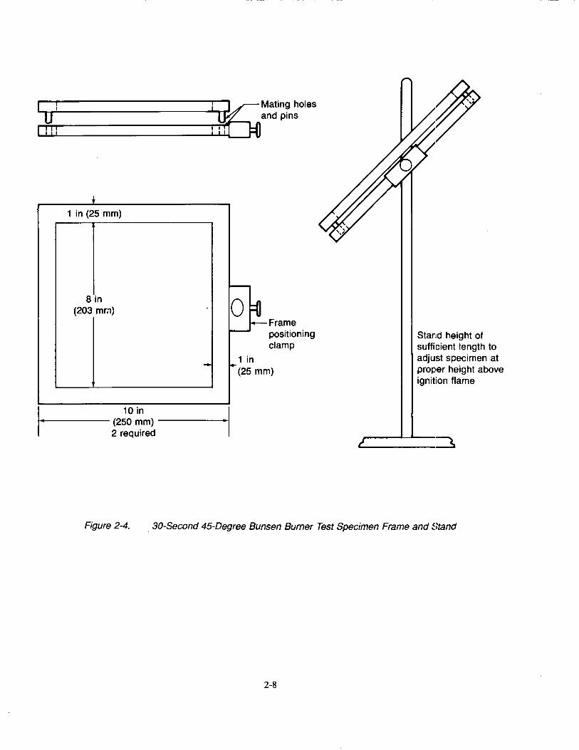
The specimen holder shall be fabricated of corrosion-resistant metal and shall be capable of securely positioning the specimen at a 45-deg angle with the vertical as shown in Figure 2.4. The holder shall be able to accommodate specimens up to 1 in (25 mm) thick.
2.3.3 Burner
The burner shall be a Bunsen or Tirrill type2 , have a% in (10 mm) inside diameter barrel, and shall be equipped with a needle valve located at the bottom of the burner barrel to adjust the gas flow rate and thereby adjust the flame height, see Figure 2-5. There shall be a means provided to move the burner into and out of test position when the cabinet door is closed.
1Suitable test chambers of the type described are manufactured by: U.S. Testing Co., 1415 Park Ave., Hoboken, NJ 07030; Custom Scientific Instruments Inc, 13 Wing Drive, Cedar Knolls, NJ 07927; and The Govmark Organization In·~ .• P.O. Box 807, Bellmore NY 11710
2A burner available as catalog number R3726A from Rascher & Betzold, Inc., 5410 N. Damen Ave., Chicago, Ill., 60625, has been found suitable.
2-1
2.3.3.1 Burner Fuel
Many fuels have been accepted, including B-gas3 , methane (99% minimum purity), natural gas (which is more than 90% methane), and propane. Methane has been found to be the most suitable burner fuel. It provides a consistent flame and does not have the problems that have been found with B-gas. It can be used without adding air through the aspirating holes at the bottom of the burner barrel, i.e., a pure diffusion flame may be used.
2.3.3.2 Plumbing for Gas Supply
The necessary gas connections and the applicable plumbing shall be essentially as specified in Figure 2-3. A control valve system with a delivery rate designed to furnish gas to the burner inlet under a pressure of 2-l!z ± V4 psi (17 ± 2 kPa) at the burner inlet shall be installed between the gas supply and the burner.
2.3.3.3 Flame Height Indicator
A flame height indicator may be used to aid in setting the height of the flame. A suitable indicator has a prong in (8 mm) in length, and is attached to the burner barrel, spaced I in (25 mm) away from the burner barrel and extending above the burner, as shown in Figure 2-5. If using methane as the burner fuel, it is desirable to have two prongs for measuring the flame height. One prong to indicate the height of the inner cone of the flame, and one prong to indicate the height of the tip of the flame. For methane, it has been determined that when the height of the inner cone is 7!8 in (22 mm) and the tip of the flame5 is 1-1/2 in (38 mm) long, the proper flame profile is achieved.
2.3.3.4 Flame Temperature Indicator
A 24-gauge Chromel-Alumel bare wire thermocouple or equivalent shall be used 1o measure flame temperature if the burner fuel is other than B-gas, methane (99% minimum purity, or natural gas.4
2.3.3.5 Burner Positioning
2.3.4 Timer
There shall be means provided to position the burner directly below the center of the specimen and also be capable of being removed at least 3 in (76 mm) away from the specimen.
A stopwatch or other device, calibrated and graduated to the nearest 0.1 sec, shall be used to measure the time of application of the burner flame, the flame time, and the glow time.
2.4 Test Specimens
2.4.1 Specimen Selection
Specimens tested shall be either cut from a fabricated part as installed in the airplane or cut from a section simulating a fabricated part, e.g., cut from a flat sheet of material or a model of the fabricated part. The specimen may be cut from any location in the fabricated part. Fabricated units, such as sandwich panels, shall not be separated into individual component layers for testing.
3B-gas, a mixture of 55% hydrogen, 18% carbon monoxide, 24% methane, and 3% ethane, has shown inconsistent burning characteristics when provided in steel cylinders. A "spike" of varying intensity is produced. It has been postulated that the carbon monoxide in the gas may react with the iron in the steel cylinders to produce iron pentacarbonyl (JFe(C0)5 ) which is volatile and may cause interference with the normal flame characteristics and may be the cause of this erratic behavior. Because of the inconsistent flame characteristics, B-gas, at least if supplied in steel cylinders, is not recommended. No data is at present available about the suitability of B-gas supplied in cylinders of other metals, such as aluminum.
4More information is available in DOT/FAA/CT-86/22, "An Investigation of the FAA Vertical Bunsen Burner Flammability Test Method."
5The tip of the methane flame is blue, transparent, and difficult to see. It is more easily seen if there is no light on the flame, as in a darkened room. The inner cone of the flame is however more visible and easily seen.
2-2

2.4.2 Specimen Number
At least three specimens shall be prepared and tested.
2.4.3 Specimen Size
The specimen shall be a square large enough to allow an exposed area of 8 in (203 mm) by 8 in (203 mm) during the test. A nominal specimen size of 10 in (254 mm) by 10 in (254 mm) has been found satisfactory; however, actual specimen size is dependent upon the details of the specimen holder selected for the test equipment.
2.4.4 Specimen Thickness
The specimen thickness shall be the same as that in the part qualified for use in the airplane, with the following exceptions:
2.4.4.1 If the part construction is used in several thicknesses, both the minimum and maximum thicknesses shall be tested.
2.4.4.3 Parts that are smaller than the size of a specimen and cannot have specimens cut from them shall be tested using a flat sheet of the material used to fabricate the part in the actual thickness used in the airplane if the thickness is not greater than Ys in (3 mm). If the part thickness is greater than 1;8 in (3 mm), the thickness used for the test specimen shall not exceed Ys in (3 mm).
2.5 Conditioning
2.5.1 Condition specimens at 70° ± 5°F (21° ± 3°C) and 50%± 5% relative humidity for 24-hr minimum. Remove only one specimen at a time from the conditioning environment immediately before testing.
2.6 Procedure
2.6.1 Burner Adjustment
2.6.1.1 If using methane as the burner fuel, ensure that the air supply to the burner is shut off.
2.6.1.2 Open the stopcock in the gas line fully and light the burner.
2.6.1.3 Measure the flame temperature in accordance with Section 2.3.3.4 to ensure it is greater than 1550°F. Adjust the needle valve on the burner to give the proper 1-lf2 in. (38 mm) flame height in accordance with Section 2.3.3.3.
2.6.2 Test Procedure
2.6.2.1 Place the burner at least 3 in (76 mm) away from where the edge of the specimen will be located during the test.
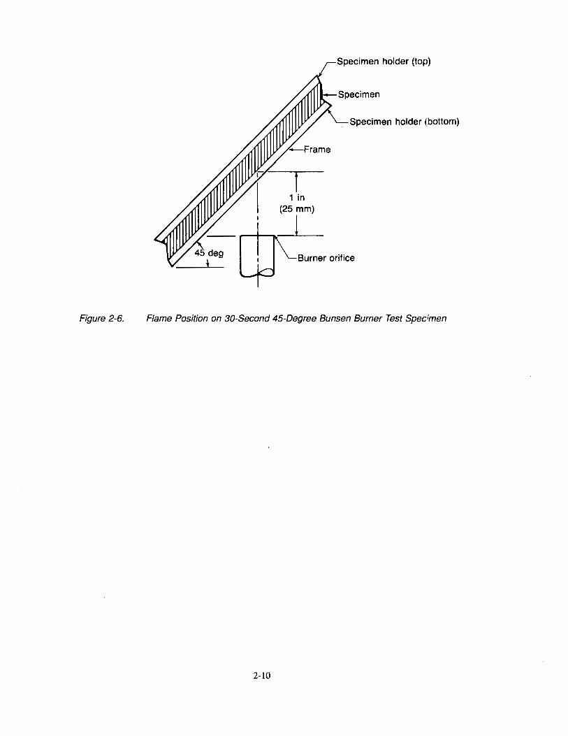
2.6.2.2 Place the specimen in the holder with the surface to be exposed when installed in the airplane toward the flame. The specimen shall be positioned such that one-third of the height of the flame is in contact with the material when the test is in progress.
2.6.2.3 Close the cabinet door, and keep it closed during the test.
2.6.2.4 Simultaneously start the timer and position the burner so that the center of the burner barrel is under the center of the bottom surface of the specimen as shown in Figure 2-6.
2.6.2.5 Apply the flame for 30 sec and then withdraw it, moving the burner at least 3 in away from the specimen.
2.6.2.6 Determine the flame time for the specimen.
2.6.2.7 Determine the glow time for the specimen.
2.6.2.8 Determine whether flame penetration occurs.
2.6.2.9 After all flaming ceases, open the cabinet door slowly to clear the test cabinet of fumes and smoke. Remove any material from the bottom of the cabinet that fell from the specimen.
1.2.6.2.10 If necessary, clean the test cabinet window prior to testing the next specimen.
2-3
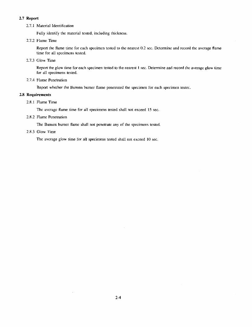
2.7 Report
2.7.1 Material Identification
Fully identify the material tested, including thickness.
2. 7.2 Flame Time
Report the flame time for each specimen tested to the nearest 0.2 sec. Determine and record the average flame time for all specimens tested.
2.7.3 Glow Time
Report the glow time for each specimen tested to the nearest 1 sec. Determine and record the average glow time for all specimens tested.
2. 7.4 Flame Penetration
Report whether the Bunsen burner flame penetrated the specimen for each specimen tested.
2.8 Requirements
2.8.1 Flame Time
The average flame time for all specimens tested shall not exceed 15 sec.
2.8.2 Flame Penetration
The Bunsen burner flame shall not penetrate any of the specimens tested.
2.8.3 Glow Time
The average glow time for all specimens tested shall not exceed 10 sec.
2-4
Door-+-...
31 in ± 1 in (787 ± 25 mm)
Figure 2-1.
IH------+-Piano hinge .,........,
/ 01 /0 /
/ / ............ 0 /
/0 .............. /
/ /
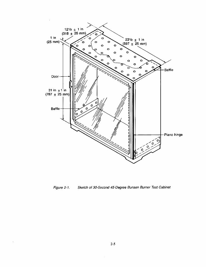
Sketch of 30-Second 45-Degree Bunsen Burner Test Cabinet
2-5
Glass
Handle ,__,
N I
0'1
TT n ~---- I
I I I I
I I
I I I I ~ I
I I I
I
I I I
I I I I I I I I
I I I I
I I I I I
I I I
I I I I I I I I
I I I I I I -------
,.. 241/a in ± 1 in ·I {613 ± 25 mm)
Door
1 in {25 mm)
~
4
31 in {787 ±
± 1 in 25 mm)
1--231/2 in ± 1 in j {597 ± 25 mm)
1/2-in dia {13 mm) holes
0.0625 in {16 ga) {1.6 mm) baffle
T 0 f . 13 in ± 1 m
{330 ± 25 mm) 3 in <t_
121/2 in ± 1 in I I j {76 mm) {317.5 mm) _
0_ o- o- _!._
1 -b-~-~- ____L 0 I I--,-
24 in ± 1 in {610 ± 25 mm)
Top View Showing Holes and Baffle
As required
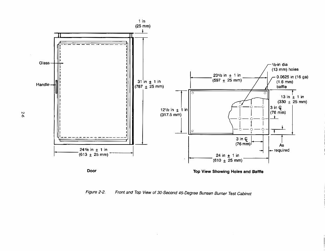
Figure 2-2. Front and Top View of 30-Second 45-Degree Bunsen Burner Test Cabinet
~2 in <t to <t (51 mm)
Left Side View
112-in dia holes both sides
(
j- 13 in ± 1 in j I-(330 mm ± 25 mm) I
II I Jl
1 in (25 mm)
t
31 in± 1 in (787 mm ± :25 mm)
2 in (51 mm)
0 0 0 0 0 oJ~ I v . "- 3/4 in 1--'.
111/2 ± 1 In , - (19 mm) m (292 ± 25m )
Right Side View
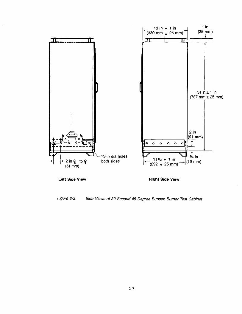
Figure 2-3. Side Views of 30-Second 45-Degree Bunsen Burner Test Cabinet
2-7
: ... .;::;.. ... : -------------r-:, r ~n~i~?n:oles ~ .. 8~·------------~-~
1 in (25 mm)
8 in (203 mm)
I 10in
1-ooo1------ (250 mm) -----•1 2 required
1 in
Frame positioning clamp
(25 mm)
Stand height of sufficient length to adjust specimen at proper height above ignition flame
Figure 2-4. 30-Second 45-Degree Bunsen Burner Test Specimen Frame and Stand
2-8
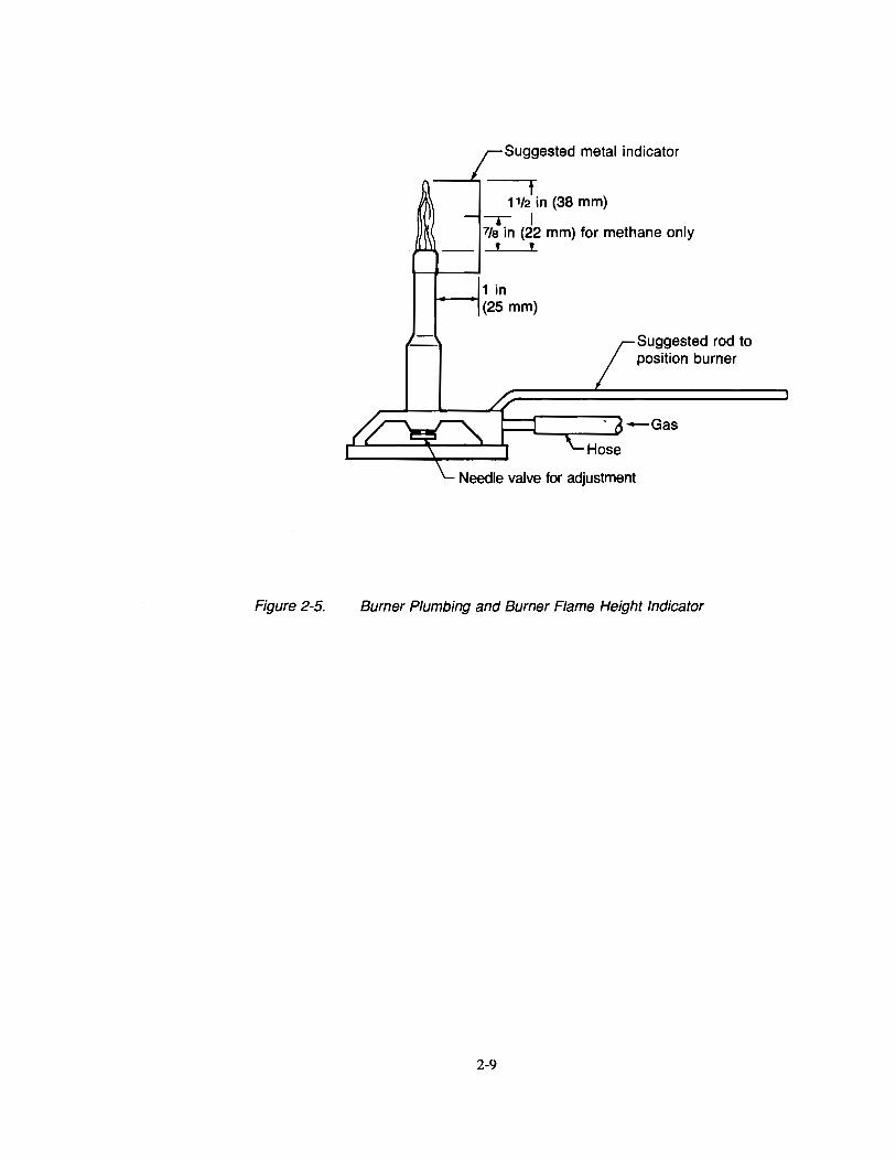
Figure 2-5.
Suggested metal indicator
t 1112 in (38 mm)
-r I 7fa in (22 mm) for methane only
' '
Suggested rod to position burner
Burner Plumbing and Burner Flame Height Indicator
2-9
Specimen holder (top)
Specimen holder (bottom)
f 1 in
(25 mm)
1 Burner orifice
Figure 2-6. Flame Position on 30-Second 45-Degree Bunsen Burner Test Specimen
2-10
Chapter 3 Horizontal Bunsen Burner Test for Cabin, Cargo Compartment,
and Miscellaneous Materials
3.1 Scope
3.1.1 This test method is intended for use in determining the resistance of materials to flame when tested according to the 15-sec horizontal Bunsen burner tests specified in FAR 25.853(b-2) and FAR 25.853(b-3).
3.2 Definitions
3.2.1 Ignition Time
The length of time the burner flame is applied to the specimen. For this test the ignition time is 15 sec.
3.2.2 Bum Rate
Bum rate is the rate at which a flame front moves over a specified distance on a test specimen, under specified test conditions. In this test, it is the rate with which a flame front moves across a test specimen mounted horizontally.
3.3 Apparatus
3.3.1 Test Cabinet
Tests shall be conducted in a draft-free cabinet 1 fabricated in accordance with Figures 3-1 to 3-3, or other equivalent enclosures acceptable to the FAA. It is suggested that the cabinet be located inside an exhaust hood to facilitate clearing the cabinet of smoke after each test. Galvanized sheet metal, 0.040 in (1 mm) thick shall be used for the bottom surface of the chamber.
3.3.2 Specimen Holder
A specimen holder fabricated of corrosion-resistant metal in accordance with Figure 3-4 shall bt: used. When performing the tests, the specimen shall be mounted in the frame so that the two long edges are held securely. The exposed area of the specimen shall be 2 in (51 mm) in width and 12 in (305 mm) in length.
3.3.3 Burner The burner shall be a Bunsen or Tirrill type2 , have a %-in (10-mm) inside diameter barrel, and shall be equipped with a needle valve located at the bottom of the burner barrel to adjust the gas flow rate and thereby adjust the flame height. There shall be a means provided to move the burner into and out of test position when the cabinet door is closed.
3.3.3.1 Burner Fuel
Many fuels have been accepted, including B-gas3, methane (99% minimum purity), natural gas (which is more than 90% methane), and propane. Methane has been found to be the most suitable burner fuel. It provides a consistent flame, and does not have the problems that have been found with B-gas. It can be used without adding air through the aspirating holes at the bottom of the burner barrel, i.e., a pure diffusion flame may be used.
1Suitable test chambers of the type described are manufactured by: U.S. Testing Co., 1415 Park Ave., Hoboken, NJ 07030; Custom Scientific Instruments Inc, 13 Wing Drive, Cedar Knolls, NJ 07927; and The Govmark Organization Inc., P.O. Box 807, Bellmore NY 11710
2A suitable burner is available from Rascher & Betzold Inc., 5410 N. Damen Ave., Chicago IL 60625, catalog no. R3726A
3B-gas, a mixture of 55% hydrogen, 18% carbon monoxide, 24% methane, and 3% ethane, has shown inconsistent burning characteristics when provided in steel cylinders. A "spike" of varying intensity is produced. It has been postulated that the carbon monoxide in the gas may react with the iron in the steel cylinders to produce iron pentacarbonyl (Fe(C0)5 ) which is volatile and may cause interference with the normal flame characteristics and may be the cause of this erratic behavior. Because of the inconsistent flame characteristics, B-gas, at least if supplied in steel cylinders, is not recommended. No data is at presenf available about the suitability of B-gas supplied in cylinders of other metals, such as aluminum.
3-1
3.3.3.2 Plumbing for Gas Supply
The necessary gas connections and the applicable plumbing shall be essentially as specified in Figure 3-3. A control valve system with a delivery rate designed to furnish gas to the burner under a pressure of 2-Yz ± lf4 psi (17 ± 2 kPa) at the burner inlet shall be installed between the gas supply and the burner.
3.3.3.3 Flame Height Indicator
A flame height indicator may be used to aid in setting the height of the flame. A suitable indicator has a prong in (8 mm) in length, and is attached to the burner barrel, spaced l in (25 mm) away from the burner barrel and extending above the burner, as shown in Figure 4-5. If using methane as the burner fuel, it is desirable to have two prongs for measuring the flame height. One prong to indicate the height of the inner cone of the flame, and one prong to indicate the height of the tip of the flame. For methane, it has been determined that when the height of the inner cone is 7/s in (22 mm) and the tip of the flame4 is l!;2 in (38 mm) long, the proper flame profile is achieved.
3.3.3.4 Flame Temperature Indicator
A 24-gauge Chromel-Alumel bare wire thermocouple or equivalent shall be used to measure flame temperature if the burner fuel is other than B-gas, methane (minimum purity), or natural gas.s
3.3.4 Timer
A stopwatch or other device, calibrated and graduated to the nearest 0.1 sec, shall be used to measure the time of application of the burner flame, the flame time, and the drip flame time.
3.3.5 Ruler
A ruler or scale calibrated to the nearest 0.1 in. (2.5 mm) shall be provided to measure gage marks and flame front position.
3.4 Test Specimens
3.4.1 Specimen Selection
Specimens tested shall be either cut from a fabricated part as installed in the aircraft or cut from a section simulating a fabricated part, e.g., cut from a flat sheet of material or a model of the fabricated part. The specimen may be cut from any location in the fabricated part. Fabricated units, such as sandwich panels, shall not be separated into individual component layers for testing.
3.4.2 Specimen Number
At least three specimens shall be prepared and tested.
3.4.3 Specimen Size
The specimen shall be a rectangle at least 2-% by 12 in (70 by 305 mm), unless the actual size used in the aircraft is smaller.
3.4.4 Specimen Thickness
The specimen thickness shall be the same as that in the part qualified for use in the aircraft, with the following exceptions:
3.4.4.1 If the part construction is used in several thicknesses, both the minimum and maximum thicknesses shall be tested.
4The tip of the methane flame is blue, transparent, and difficult to see. It is more easily seen if there is no light on the flame, as in a darkened room. The inner cone of the flame is however more visible and easily seen.
5More information is available in DOT/FAA/CT-86/22, "An Investigation of the FAA Vertical Bunsen Burner Flammability Test Method."
3-2
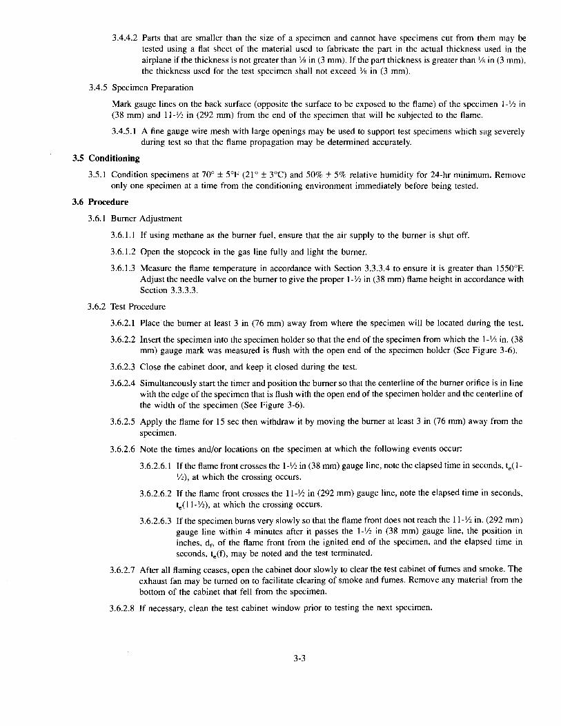
3.4.4.2 Parts that are smaller than the size of a specimen and cannot have specimens cut from them may be tested using a fiat sheet of the material used to fabricate the part in the actual thickness used in the airplane if the thickness is not greater than Vs in (3 mm). If the part thickness is greater than Vs in (3 mm), the thickness used for the test specimen shall not exceed Ys in (3 mm).
3.4.5 Specimen Preparation
Mark gauge lines on the back surface (opposite the surface to be exposed to the flame) of the specimen l-Y2 in (38 mm) and 11-112 in (292 mm) from the end of the specimen that will be subjected to the flame.
3.4.5.1 A fine gauge wire mesh with large openings may be used to support test specimens which sag severely during test so that the flame propagation may be determined accurately.
3.5 Conditioning
3.5.1 Condition specimens at 70° ± 5°F (21° ± 3°C) and 50%± 5% relative humidity for 24-hr minimum. Remove only one specimen at a time from the conditioning environment immediately before being tested.
3.6 Procedure
3.6.1 Burner Adjustment
3.6.1.1 If using methane as the burner fuel, ensure that the air supply to the burner is shut off.
3.6.1.2 Open the stopcock in the gas line fully and light the burner.
3.6.1.3 Measure the flame temperature in accordance with Section 3.3.3.4 to ensure it is greater than 1550°F. Adjust the needle valve on the burner to give the proper 1-Yz in (38 mm) flame height in accordance with Section 3.3.3.3.
3.6.2 Test Procedure
3.6.2.1 Place the burner at least 3 in (76 mm) away from where the specimen will be located during the test.
3.6.2.2 Insert the specimen into the specimen holder so that the end of the specimen from which the I-Y2 in. (38 mm) gauge mark was measured is flush with the open end of the specimen holder (See Figure 3-6).
3.6.2.3 Close the cabinet door, and keep it closed during the test.
3.6.2.4 Simultaneously start the timer and position the burner so that the centerline of the burner orifice is in line with the edge of the specimen that is flush with the open end of the specimen holder and the centerline of the width of the specimen (See Figure 3-6).
3.6.2.5 Apply the flame for 15 sec then withdraw it by moving the burner at least 3 in (76 mm) away from the specimen.
3.6.2.6 Note the times and/or locations on the specimen at which the following events occur:
3.6.2.6.1 If the flame front crosses the I- 1/2 in (38 mm) gauge line, note the elapsed time in seconds, te( 1-Vz), at which the crossing occurs.
3.6.2.6.2 If the flame front crosses the ll-Y2 in (292 mm) gauge line, note the elapsed time in seconds, te(ll-Y2), at which the crossing occurs.
3.6.2.6.3 If the specimen bums very slowly so that the flame front does not reach the ll-Y2 in. (292 mm) gauge line within 4 minutes after it passes the l- 1/2 in (38 mm) gauge line, the position in inches, df, of the flame front from the ignited end of the specimen, and the elapsed time in seconds, te(f), may be noted and the test terminated.
3.6.2.7 After all flaming ceases, open the cabinet door slowly to clear the test cabinet of fumes and smoke. The exhaust fan may be turned on to facilitate clearing of smoke and fumes. Remove any material from the bottom of the cabinet that fell from the specimen.
3.6.2.8 If necessary, clean the test cabinet window prior to testing the next specimen.
3-3
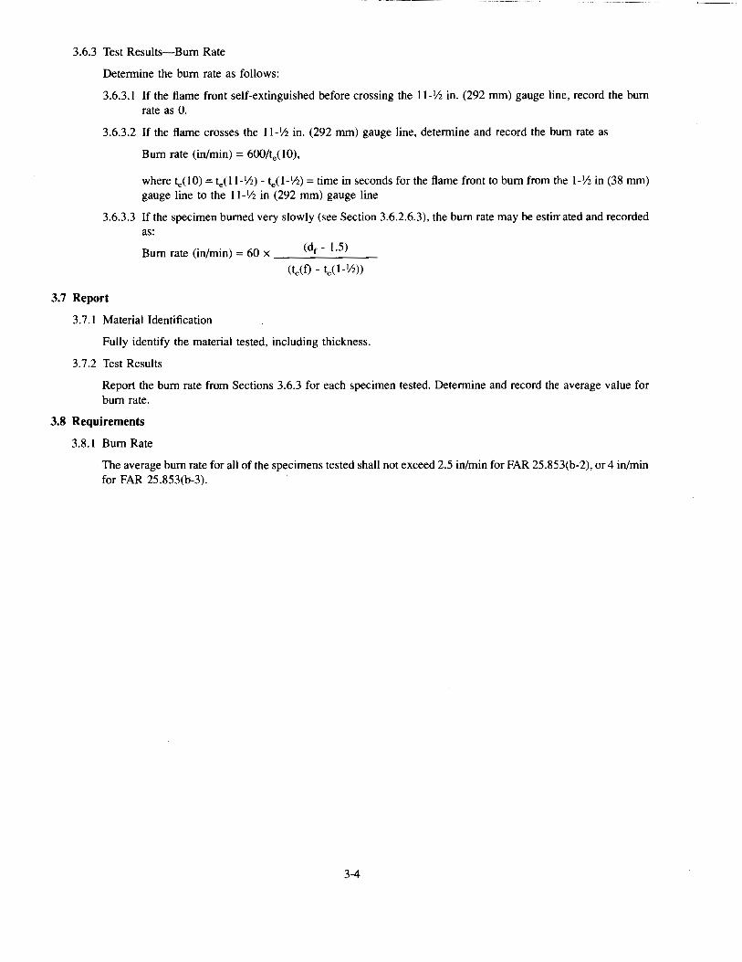
3.6.3 Test Results-Bum Rate
Determine the burn rate as follows:
3.6.3.1 lfthe flame front self-extinguished before crossing the 11-Vz in. (292 rom) gauge line, record the burn rate as 0.
3.6.3.2 If the flame crosses the 11-1/z in. (292 rom) gauge line, determine and record the burn rate as
Burn rate (in/min) = 600/te(lO),
where te(lO) = te(11-IIz)- te(l- 1/z) =time in seconds for the flame front to burn from the Ph in (38 rom) gauge line to the 1 t-1/z in (292 rom) gauge line
3.6.3.3 If the specimen burned very slowly (see Section 3.6.2.6.3), the burn rate may be estimated and recorded as:
Burn rate (in/min) = 60 x ___ (d_f_-_1_·5_) __
(te(f)- te(l-IIz))
3.7 Report
3.7.1 Material Identification
Fully identify the material tested, including thickness.
3.7.2 Test Results
Report the burn rate from Sections 3.6.3 for each specimen tested. Determine and record the average value for burn rate.
3.8 Requirements
3.8.1 Burn Rate
The average burn rate for all of the specimens tested shall not exceed 2.5 in/min for FAR 25.853(b-2), or 4 in/min for FAR 25.853(b-3).
3-4
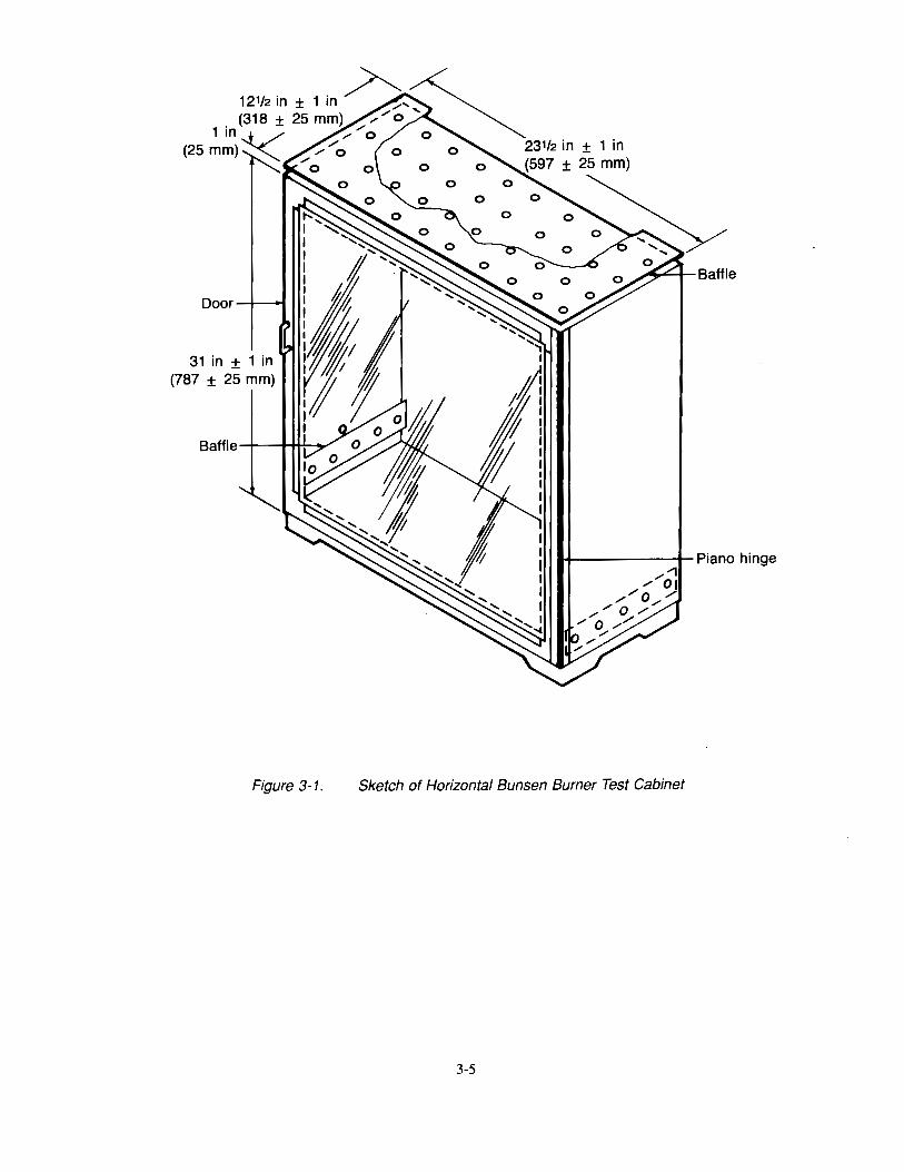
Door ---4--~
31 in ± 1 in (787 ± 25 mm)
Figure 3-1.
1+------4-Piano hinge
Sketch of Horizontal Bunsen Burner Test Cabinet
3-5
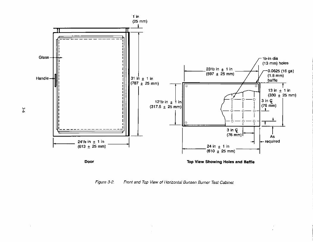
Glass
Handle -
VJ I
0'1
I·
Jl
,--I I I I I
--~---------------
241/a in ± 1 in (613 ± 25 mm)
Door
c:;,.,, ... _ I:J I') I I~UIV v-c..
_I -,
fin (25 mm)
~
31 in (787 :
± 1 in
1----231/2 in ± 1 in I (597 ± 25 mm)
25 mm)
112-in dia (13 mm) holes
0.0625 (16 ga) (1.6 mm) baffle
(330 ± 25 mm) T 0 13 in +f1 in
12112 in± 1 in o1
-o-o 3 in <t (317.5 ± 25 mm) I I (76 mm)
1 -,-,_, _ _L
o -o-o-o- --,---i-~=============L----~~--~I_J ___ ~~L
...._ ____ 24 in ± 1 in (610 ± 25 mm)
Top View Showing Holes and Baffle
As required
F;ont and Top View of Ho;izontal Bunsen Burner Test Cabinet

112-in dia 6 holes both sides
(
1- 13 in ± 1 in j 1 in
I ""TT (330 ± 25 mm) ~L I
_jl I II I
I
I
0 0 0 I 0 0
.../ T
1-- 11112 in ± 1 in (292 ± 25 mm)
ol:
'---
31 in± 1 in (787 ± 25 mm)
I 2 in ± 1/4 in (51 ± 6 mm)
__ ..!..__
I-3/4 in (19 rnm)
Left Side View Right Side View
Figure 3-3. Side Views of Horizontal Bunsen Burner Test Cabinet
3-7
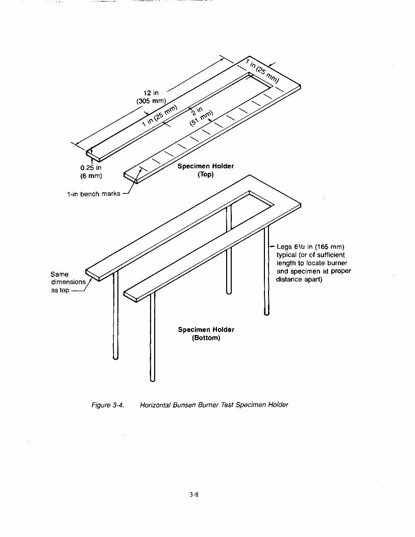
1-in bench marks
Same
Figure 3-4.
Specimen Holder (Bottom)
Legs 61/2 in (165 mm) typical (or of sufficient length to locate burner and specimen at proper distance apart)
Horizontal Bunsen Burner Test Specimen Holder
3-8
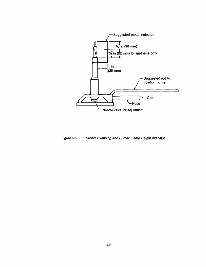
Figure 3-5.
Suggested metal indicator
t 11J2 in (38 mm)
-r r 7/a in (22 mm) for methane only
J J
Suggested rod to position burner
Burner Plumbing and Burner Flame Height Indicator
3-9
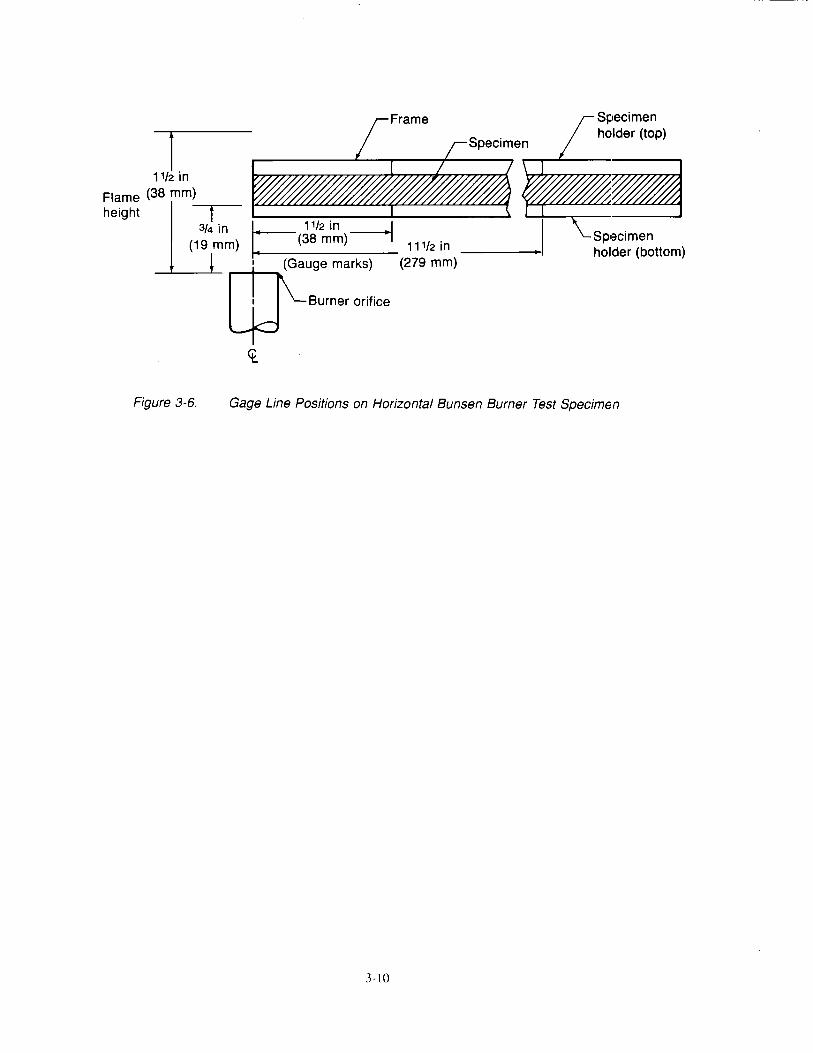
I 1112 in
Flame (38 mm)
height H . 3/4 in 11/2 m
(19 mm) 1: (38 mm)
• (Gauge marks)
WBurner orifice
<t
11112 in (279 mm)
Sp•3cimen holder (bottom)
Figure 3-6. Gage Line Positions on Horizontal Bunsen Burner Test Specimen
3-10
Chapter 4 60-Deg Bunsen Burner Test for Electric Wire
4.1 Scope
4.2.1 This test method is intended for use in determining the resistance of electric wire insulation to flame when tested according to the 30-sec 60-deg Bunsen burner test specified in FAR 25.1359.
4.2 Definitions
4.2.1 Ignition Time
Ignition time is the length of time the burner flame is applied to the specimen. The ignition time for this test is 30 sec.
4.2.2 Flame Time
Flame time is the time in seconds that the specimen continues to flame after the burner flame is removed from beneath the specimen. Surface burning that results in a glow but not in a flame is not included.
4.2.3 Drip Flame Time
Drip flame time is the time in seconds that any flaming material continues to flame after falling from the specimen to the floor of the chamber. If there is more than one drip, the drip flame time reported is that of the longest flaming drip. If succeeding flaming drips reignite earlier drips that flamed, the drip flame time reported is the total of flaming drips.
4.2.4 Bum Length
Bum length is the length of damage along the wire, both above and below the point of burner flame impingement, due to that area's combustion, including areas of partial consumption, charring, or embrittlement, but not including areas sooted, stained, warped, or discolored, nor areas where material has shrunk or melted away from the heat.
4.3 Apparatus
4.3.1 Test Enclosure and Setup
Tests shall be conducted in a cabinet fabricated of sheet metal, approximately 24 in ( 610 mm) high by 12 in (305 mm) by 12 in (305 mm), and open at the front and top. External conditions around the cabinet shall be such that the cabinet is free of drafts during a test, but sufficient airflow shall be available for complete combustion. Other cabinets may be used if they are draft-free and have enough air to allow complete combustion. The back wall of the cabinet may be painted flat black to facilitate viewing of any flame. It is suggested that the cabinet be located inside an exhaust hood to facilitate removal of smoke and fumes after each test.
4.3.2 Specimen Holder
A specimen holder fabricated of corrosion-resistant metal in accordance with Figure 4-1 shall be used. The specimen holder shall be placed so that the specimen is maintained at an angle of 60 deg with the horizontal, and be positioned parallel to and 6 in (152 mm) back from the front of the enclosure.
4.3.2.1 Clamp and Pulley
The specimen shall be attached to the specimen holder by a clamp at the lower end and a pulley or rod at the upper end. The span between the clamp and the rod or pulley shall be 24 in (610 mm).
4.3.2.2 Weight
A weight shall be attached to the free end of the specimen to keep the specimen taut during the test. See Figure 4-1. Suggested weights for various wire sizes are shown in the following table:
4-1
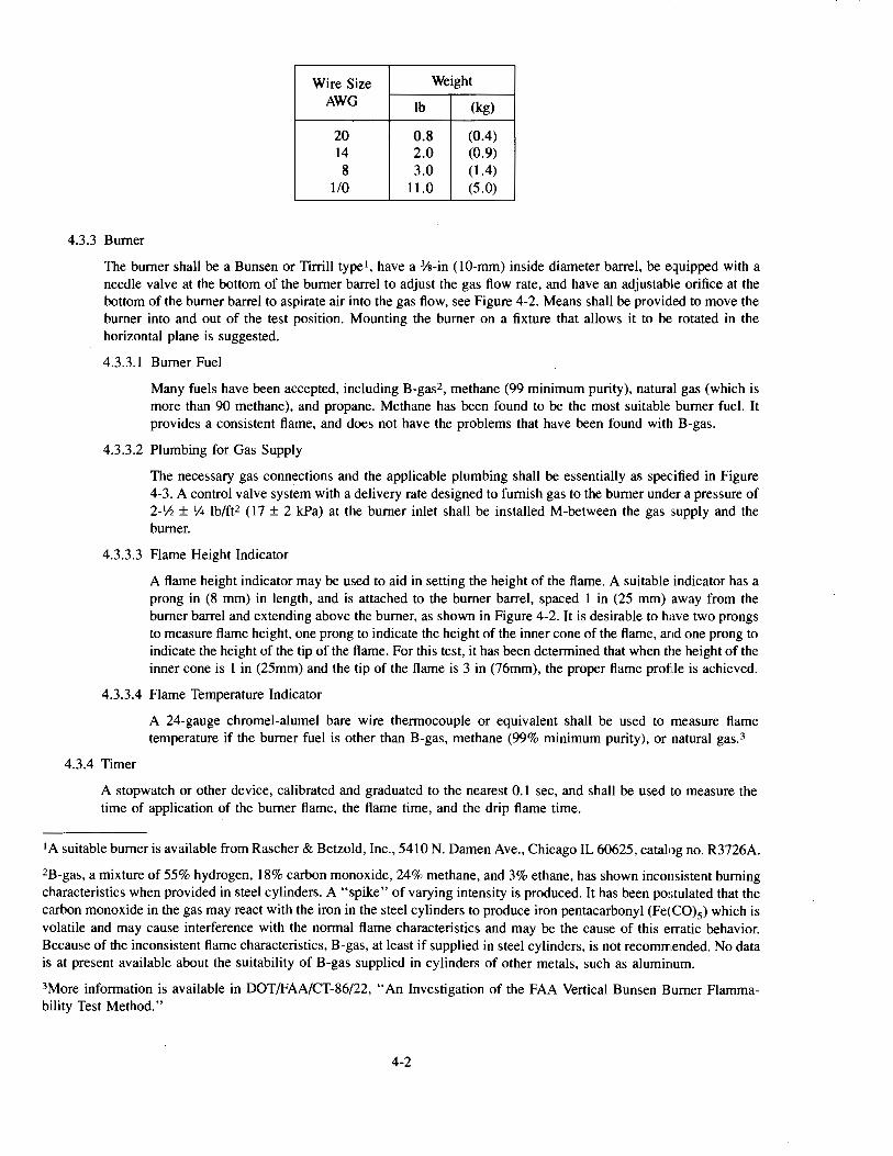
Wire Size Weight
AWG lb (kg)
20 0.8 (0.4) 14 2.0 (0.9) 8 3.0 (1.4)
1/0 11.0 (5.0)
4.3.3 Burner
The burner shall be a Bunsen or Tirrill typei, have a %-in (10-mm) inside diameter barrel, be equipped with a needle valve at the bottom of the burner barrel to adjust the gas flow rate, and have an adjustable orifice at the bottom of the burner barrel to aspirate air into the gas flow, see Figure 4-2. Means shall be provided to move the burner into and out of the test position. Mounting the burner on a fixture that allows it to be rotated in the horizontal plane is suggested.
4.3.3.1 Burner Fuel
Many fuels have been accepted, including B-gas2, methane (99 minimum purity), natural gas (which is more than 90 methane), and propane. Methane has been found to be the most suitable burner fuel. It provides a consistent flame, and does not have the problems that have been found with B-gas.
4.3.3.2 Plumbing for Gas Supply
The necessary gas connections and the applicable plumbing shall be essentially as specified in Figure 4-3. A control valve system with a delivery rate designed to furnish gas to the burner under a pressure of 2- 1/2 ± 1;4 lb/ft2 (17 ± 2 kPa) at the burner inlet shall be installed M-between the gas supply and the burner.
4.3.3.3 Flame Height Indicator
A flame height indicator may be used to aid in setting the height of the flame. A suitable indicator has a prong in (8 mm) in length, and is attached to the burner barrel, spaced 1 in (25 mm) away from the burner barrel and extending above the burner, as shown in Figure 4-2. It is desirable to have two prongs to measure flame height, one prong to indicate the height of the inner cone of the flame, and one prong to indicate the height of the tip of the flame. For this test, it has been determined that when the height of the inner cone is 1 in (25mm) and the tip of the flame is 3 in (76mm), the proper flame proftle is achieved.
4.3.3.4 Flame Temperature Indicator
4.3.4 Timer
A 24-gauge chromel-alumel bare wire thermocouple or equivalent shall be used to measure flame temperature if the burner fuel is other than B-gas, methane (99% minimum purity), or natural gas.3
A stopwatch or other device, calibrated and graduated to the nearest 0.1 sec, and shall be used to measure the time of application of the burner flame, the flame time, and the drip flame time.
1A suitable burner is available from Rascher & Betzold, Inc., 5410 N. Damen Ave., Chicago IL 60625, catalog no. R3726A.
2B-gas, a mixture of 55% hydrogen, 18% carbon monoxide, 24% methane, and 3% ethane, has shown inconsistent burning characteristics when provided in steel cylinders. A "spike" of varying intensity is produced. It has been postulated that the carbon monoxide in the gas may react with the iron in the steel cylinders to produce iron pentacarbonyl (Fe(CO)s) which is volatile and may cause interference with the normal flame characteristics and may be the cause of this erratic behavior. Because of the inconsistent flame characteristics, B-gas, at least if supplied in steel cylinders, is not recommended. No data is at present available about the suitability of B-gas supplied in cylinders of other metals, such as aluminum.
3More information is available in DOT/FAA/CT-86/22, "An Investigation of the FAA Vertical Bunsen Burner Flammability Test Method."
4-2
4.3.5 Ruler
A ruler or scale calibrated and graduated to the nearest 0.1 in (2.5 mm) shall be provided to measure the bum length.
4.4 Test Specimens
4.4.1 Specimen Number
At least three specimens of each wire type shall be prepared and tested.
4.4.2 Specimen Length
The specimens shall be cut to a length of 30 in (762 mm). The specimen span between the lower clamp and upper pulley or rod shall be 24 in (610 mm).
4.4.3 Specimen Preparation
Make a gauge mark 8 in (203 mm) from one end of each specimen.
4.5 Conditioning
4.5.1 Condition specimens at 70° ± 5°F (21 o ± 3°C) and 50% ± 5% relative humidity for 24-hr minimum unless otherwise specified. Remove only one specimen at a time from the conditioning environment immediately before being tested.
4.6 Test Procedure
4.6.1 Burner Adjustment
4.6.1.1 If using methane as the burner fuel, ensure that the air supply to the burner is shut off.
4.6.1.2 Open the stopcock in the gas line fully and light the burner.
4.6.1.3 Adjust the burner flame to obtain a flame profile such that the outer cone of the flame is 3 in (76 mm) in length, and the inner cone is approximately 1 in (25 mm) in length. The proper flame length shall be obtained by adjusting the needle valve on the burner controlling the gas flow rate and the orifice controlling the amount of aspirated air into the gas line.
4.6.1.4 Measure the flame temperature in accordance with Section 4.3.3.4 to assure it is at least 1 ,750°F.
4.6.1.5 For the test, place the burner into position so that 1) the top end of the burner barrel is one inch from the mark on the specimen, 2) the centerline of the burner barrel is perpendicular to and to the underside of the mark on the specimen, and 3) the centerline of the burner barrel forms an angle of 30° with the line which is in the vertical plane containing both ends of the specimen, is perpendicular to the specimen, and passes through the mark on the specimen. It has been found convenient to fabricate a fixture to position and hold the location of the burner quickly and repeatably.
4.6.2 Test Procedure
4.6.2.1 Place the burner at least 3 in (76 mm) away from where the specimen will be located during the test.
4.6.2.2 Simultaneously start the timer and position the burner as described in Section 4.6.1.4 so that the tip of the inner cone of the burner flame contacts the gauge mark on the wire.
4.6.2.3 Apply the flame for 30 sec and then withdraw it.
4.6.2.4 If flaming material falls from the test specimen, note the drip flame time for the specimen. See Section 4.2.3.
4.6.2.5 Determine the flame time for the specimen. See Section 4.2.2.
4.6.2.6 After all flaming ceases, remove the specimen and determine the bum length. To facilitate determining the bum length, a dry soft cloth or tissue, or a soft cloth or tissue dampened with a moderate solvent that does not dissolve or attack the specimen material, such as alcohol, may be used to remove soot and stain particles from tested specimens.
4-3
~ 4.6.2.7 Remove any material from the bottom of the cabinet that fell from the specimen.
4.7 Report
4. 7.1 Material Identification
Fully identify the wire tested.
4.7.2 Test Results
4. 7 .2.1 Report the flame time for each specimen tested. Determine and record the average value~ for flame time.
4.7.2.2 Report the drip flame time for each specimen tested. Determine and record the average value for drip flame time. For specimens that have no drips, record "0" for the drip flame time and also record "No Drips."
4. 7 .2.3 Report the bum length for each specimen tested. Determine and record the average value for bum length.
4.8 Requirements
4.8.1 Extinguishing Time
The average extinguishing time for all of the specimens tested shall not exceed 30 sec.
4.8.2 Drip Extinguishing Time
The average drip extinguishing time for all of the specimens tested shall not exceed 3 sec.
4.8.3 Bum Length
The average bum length for all of the specimens tested shall not exceed 3 in (76 mm).
4.8.4 Wire Breakage
It shall not be considered a failure if the wire breaks during the test.
4-4
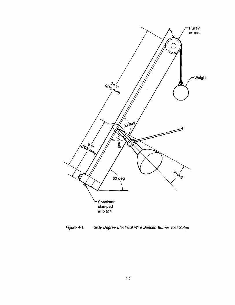
Figure 4-1.
Specimen clamped in place
Sixty Degree Electrical Wire Bunsen Burner Test Setup
4-5
Weight

Figure 4-2.
Suggested metal indicator
f 3 in (76 mm)
--. I ·1 in (25 mm)
t t
Suggested rod to position burner
Burner Plumbing and Burner Flame Height Indicator
4-6
Chapter 5 Heat Release Rate Test for Cabin Materials
5.1 Scope
5.1.1 This test is intended for use in determining heat release rates to show compliance with the requirements of FAR 25.853(a-l) through Amendment 25-66 and FAR 12l.312(a)(l) through Amendment 121-198.
5.1.2 Heat release is measured for the duration of the test from the moment the specimen is injected into the controlled exposure chamber, and encompasses the period of ignition and progressive flame involvement of the surface.
5.2 Definitions
5.2.1 Heat Release
A measure of the amount of heat energy evolved by a material when burned. It is expressed in terms of energy per unit area (kilowatt-minutes per square meter- kW-min/m2).
5.2.2 Heat Release Rate
A measure of the rate at which heat energy is evolved by a material when burned. It is expressed in terms of power per unit area (kilowatts per square meter - kW/m2). The maximum heat release rate occurs when the material is burning most intensely.
5.2.3 Heat Flux Density
The intensity of the thermal environment to which a sample is exposed when burned. In this test, the heat flux density used is 3.5 W/cm2.
5.3 Test Apparatus
5.3.1 Release Rate Apparatus
The apparatus shown in Figures 5-1a and 5-1b shall be used to determine heat release rates. All exterior surfaces of the apparatus, except the holding chamber, shall be insulated with l-in (25-mm) thick, low-density, hightemperature, fiberglass board insulation1• A gasketed door, through which the sample injection rod slides, shall be provided to form an airtight closure on the specimen hold chamber.
5.3.2 Thermopile
The temperature difference between the air entering the environmental chamber and that leaving shall be monitored by a thermopile having five hot and five cold 24-gauge chromel-alumel junctions. The loop to be formed by the thermocouple junction shall be 0.050 ± 0.010 in (1.3 ± 0.3 mm) in diameter. The cold junctions shall be located in the pan below the air distribution plate. See Section 5.3.4. The hot junctions shall be located 0.38in (10 mm) below the top of the chimney. One of the hot junctions shall be placed at the center of the chimney's cross section, and the other four shall be placed on the chimney diagonals 1.18 in (30 mrn) from the center thermocouple.
5.3.3 Radiant Heat Source
A radiant heat source for generating a flux up to 10 W/cm2, using four silicon carbide elements Type LL, 20 in (508 mm) by 0.63 in (16 mm), nominal resistance 1.4 ohms, as shown in Figures 5-la and 5-1b, and 5-2, shall be used. The silicon carbide elements shall be mounted in the stainless steel panel box by inserting them through 0.63-in (16 mm) holes in 0.03-in (1 mm) thick ceramic fiber or calcium-silicate millboard. Locations of the holes in the pads and stainless steel covered plates shall be as shown in Figure 5-2. A truncated diamond-shaped mask constructed of 0.042 ± 0.002 in (1.07 ± 0.05 mm) stainless steel shall be added to provide uniform heat flux density over the area occupied by the 5.94-in by 5.94-in (151-mm by 151-mm) vertical sample. An adjustable power supply capable of producing 12.5 kVA shall be provided. The heat flux density over the specimen surface
!Owens-Coming Flat Duct Board, Type 475-FR, density 4 lb/ft3 (65 kg/m3), thermal conductivity 10 BTU/ft=!-min (0.033 W/m2-K), 1 in thick (25 mm), or its equivalent have been found satisfactory.
5-1
when set at 3.5 w/cm2 shall be uniform within 5%, and shall be checked periodically and after each heating element change. Uniformity of heat flux density shall be determined by calorimeter measurements at the center and at the four comers of the specimen surface.
5.3.4 Air Distribution System
The air entering the apparatus shall be 70° to 75° F (21 o to 24° C) and set at approximately 85 ft3/min (0.04 m3/s) using an orifice meter. The orifice meter shall be comprised of a squared-edged circular plate orifice, 0.020 in (0.5 mm) thick, located in a circular pipe with a diameter of 1.50 in (38 mm), with two pressure measuring points located 1.50 in (38 mm) above and 0.75 in (20 mm) below the orifice and connected to a mercury manometer. The inlet pipe shall remain 1.50 in (38 mm) in diameter. See Figure 5-la.
5.3.4.1 The air entering the environmental chamber shall be distributed by a 0.25-in (63-mm) thick aluminum plate having eight No.4 drill holes, 2 in (51 mm) from the sides on 4-in (102-mm) centers, mounted at the base of the environmental chamber. A second plate having 120 evenly spaced, No. 28 drill holes shall be mounted 6 in (152 mm) above the aluminum plate. See Figure 5-lb.
5.3.4.2 The air supply manifold at the base of the pyramidal section shall have 48 evenly spaced, No. 26 drill holes 0.38 in ( 10 mm) from the inner edge of the manifold, resulting in an airflow split of approximately three to one within the apparatus. See Figure 5-la.
5.3.5 Exhaust Stack
An exhaust stack, 5.25 .. by 2.75 in (133 by 70 mm) in cross section, and 10 in (254 mm) long, fabricated from stainless steel, shall be mounted on the outlet of the pyramidal section. See Figures 5-la and 5-lb. A 1.0-in by 3.0-in (25-by 76-mm) plate of 0.018 ± 0.002 in (0.50 ± 0.05 mm) stainless steel shall be centered inside the stack, perpendicular to the airflow, 3 in (76 mm) above the base of the stack.
5.3.6 Specimen Holders
Specimen holders shall be fabricated of stainless steel sheet 0.017 ± 0.002 in (0.43 ± 0.05 mm) thick as shown in Figure 5-3. Specimen holders shall be attached to the injection rod using the support shown in Figure 5-3. Each holder shall be provided with a "V" -shaped spring pressure plate. The position of the spring pressure plate may be changed to accommodate different specimen thicknesses by inserting the retaining rod in different holes of the specimen holder frame. Each holder shall also have two wires attached to the front of the holder to secure the face of the specimen in the holder.
5.3.6.1 Drip Pan
A drip pan shall be fabricated of stainless steel sheet 0.017 ± 0.002 in (0.43 ± 0.05 mm) thick as shown in Figure 5-3 and be attached to the specimen holder using the flanges shown in Figure 5-3. Drip pans may be needed to prevent melting specimens from dripping into the lower pilot burner. Foil may be used to line the drip pan to facilitate cleaning after use.
5.3.7 Calorimeter
A water-cooled, total heat flux density, foil type Gardon Gauge calorimeter shall be used to measure the total heat flux density at a point where the center of the specimen surface is located at the start of the test. When positioned to measure flux density, the sensing surface of the meter shall be flush with the suppmting device surface so that air heated by such a support does not contact the sensing surface of the meter.
5.3.8 Pilot Burners
Pilot burners shall be placed at the bottom and top of the specimens. The burners shall be constructed of stainless steel tubing with a 0.25-in (6.4-mm) outside diameter and 0.03-in (0.8-mm) wall thickness.
5.3.8.1 Lower Pilot Burner
The lower pilot burner shall be located as shown in Figure 5-1 a. The lower pilot burner shall have its centerline perpendicular to the surface of the specimen and 0.19 in (5 mm) above the specimen's lower exposed edge, and shall have its end 0.38 in (10 mm) from the specimen surface. A methane-air mixture shall be used consisting of 0.004 ft3/min (120 cm3/min) (at standard temperature and pressure) methane
5-2
(99% minimum purity) and an air supply, adjusted to produce a flame such that the inner cone is approximately the same length as the diameter of the flame.
5.3.8.1.1 Spark Ignitor
A spark ignitor may be installed to ensure that the lower pilot burner remains burning. A test is invalidated if the lower pilot burner becomes extinguished for any period that exceeds 3 sec. A circuit for a satisfactory device is sketched in Figure 5-4.
5.3.8.2 Upper Pilot Burner
An upper pilot burner shall be provided to produce flame lets above the test specimen to ignite flammable gases. If any of the flamelets on the upper pilot burner extinguishes for a period longer than 3 sec during the test, the test is invalidated.
The upper pilot burner shall be constructed from a piece of stainless steel tubing with an outside diameter (OD) of 0.25 in (6.3 mm) and a wall thickness of in (0.8 mm). The tubing shall be inserted into the environmental chamber through a 0.25 in (6.3 mm) hole drilled 0.38 in (10 mm) above the upper edge of the window frame, and be supported and positioned by an adjustable "Z" -shaped bracket mounted outside the environmental chamber above the viewing window. The tubing shall be located 0.75 in (19 mm) above and 0.75 in (19 mm) behind the upper front edge of the specimen holder, and installed such that the holes are directed horizontally toward the radiant heat source. One end of the tubing shall be closed with a silver solder plug or equivalent.
5.3.8.2.1 Standard Three-hole Burner
The standard three-hole upper pilot burner shall be constructed from a piece of 0.25 in (66 mm) OD tubing 14 in (360 mm) long. Three No. 40 (0.098-in (2.5-mm) diameter) drill holes, each radiating in the same direction, shall be drilled into the tubing. The holes shall be spaced 2.38 in (60 mm) apart, with the first hole located 0.19 in (5 mm) from the closed end, as is shown in Figure 5-5a. The burner shall be positioned above the specimen holder so that the middle hole lies in the plane perpendicular to the exposed surface of the specimen and passes through its vertical centerline.
The burner fuel shall be methane of 99% minimum purity. The fuel flow rate shall be: adjusted to produce flamelets 1 in (25 mm) in length that bend upwards slightly above the bumer tube.
5.3.8.2.2 Optional Fourteen-hole Burner
5.4 Test Specimens
5.4.1 Specimen Size
An optional burner that has been found satisfactory by the FAA is as follows. This burner has a greater probability of reigniting flamelets which may extinguish during a test.
Fourteen No. 59 drill holes, each radiating in the same direction, shall be drilled into a. 15.75 in in (400 mm) length of 0.25 in (6 mm) OD tubing. The holes shall be spaced 0.50 in (13 mm)apart with the first hole located 0.50 in (13 mm) from the closed end, as shown in Figure 5-5b. The burner shall be positioned above the specimen holder so that the holes are placed above the specimen holder as shown in Figure 5-5b.
The fuel fed to this burner shall be methane of 99% minimum purity mixed with air in a ratio of approximately 50/50 by volume. The total fuel flow shall be adjusted to provide flamelets 1 in (25 mm) long. When the gas/air ratio and its fuel flow rate are properly adjusted, approximately 0.25 in (6 mm) of the flame length appears yellow in color.
The standard size for specimens is 5.94 + 0, -0.06 by 5.94 + 0, -0.06 in (150 +0,-2 by 150 +0,-2 mm) in lateral dimensions. Specimen thickness is as used in the relevant application up to 1.75 (45 mm); applications requiring thicknesses greater than 1.75 in (45 mm) shall be tested in 1-% in (45 mm) thicknesses.
5.4.2 Specimen Number
A minimum of three specimens shall be prepared and tested for each material/part.
5-3
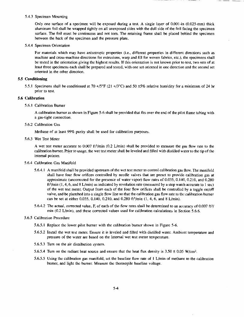
5.4.3 Specimen Mounting
Only one surface of a specimen will be exposed during a test. A single layer of 0.001-in (0.025-mm) thick aluminum foil shall be wrapped tightly on all unexposed sides with the dull side of the foil facing the specimen surface. The foil must be continuous and not torn. The retaining frame shall be placed behind the specimen between the back of the specimen and the pressure plate.
5.4.4 Specimen Orientation
For materials which may have anisotropic properties (i.e., different properties in different directions such as machine and cross-machine directions for extrusions, warp and fill for woven fabrics, etc.), the specimens shall be tested in the orientation giving the highest results. If this orientation is not known prior to test, two sets of at least three specimens each shall be prepared and tested, with one set oriented in one direction and the second set oriented in the other direction.
5.5 Conditioning
5.5.1 Specimens shall be conaitioned at 70 +/5°F (21 +/3°C) and 50 ±5% relative humidity for a minimum of 24 hr prior to test.
5.6 Calibration
5.6.1 Calibration Burner
A calibration burner as shown in Figure 5-6 shall be provided that fits over the end of the pilot flame tubing with a gas-tight connection.
5.6.2 Calibration Gas
Methane of at least 99% purity shall be used for calibration purposes.
5.6.3 Wet Test Meter
A wet test meter accurate to 0.007 ft3/min (0.2 L/min) shall be provided to measure the gas flow rate to the calibration burner. Pri_or to usage, the wet test meter shall be leveled and filled with distilled water to the tip of the internal pointer.
5.6.4 Calibration Gas Manifold
5 .6.4.1 A manifold shall be provided upstream of the wet test meter to control calibration gas flow. The manifold shall have four flow orifices controlled by needle valves that are preset to provid~: calibration gas at approximate (uncorrected for the presence of water vapor) flow rates of 0.035, 0.140, 0.21 0, and 0.280 ft3/min (1, 4, 6, and 8 L/min) as indicated by revolution rate (measured by a stop watch accurate to 1 sec) of the wet test meter. Output from each of the four flow orifices shall be controlled by a toggle on/off valve, and be plumbed into a single flow line so that the calibration gas flow rate to the calibration burner can be set at either 0.035, 0.140, 0.210, and 0.280 ft3/min (1, 4, 6, and 8 L/min).
5.6.4.2 The actual, corrected value, F, of each of the flow rates shall be determined to an accuracy of 0.007 ft3f
min (0.2 L/min), and these corrected values used for calibration calculations in Section 5.6.6.
5.6.5 Calibration Procedure
5.6.5.1 Replace the lower pilot burner with the calibration burner shown in Figure 5-6.
5.6.5.2 Install the wet test meter. Ensure it is leveled and filled with distilled water. Ambie:nt temperature and pressure of the water are based on the internal wet test meter temperature.
5.6.5.3 Turn on the air distribution system.
5.6.5.4 Turn on the radiant heat source and ensure that the heat flux density is 3.50 ± 0.05 W/cm2.
5.6.5.5 Using the calibration gas manifold, set the baseline flow rate of 1 L/min of methane to the calibration burner, and light the burner. Measure the thermopile baseline voltage.
5-4
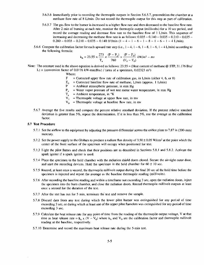
5.6.5.6 Immediately prior to recording the thermopile outputs in Section 5.6.5.7, precondition the chamber at a methane flow rate of 8 L/min. Do not record the thermopile output for this step as part of calibration.
5.6.5.7 The gas flow to the burner is increased to a higher flow rate and then decreased to the baseline flow rate. After 2 min of burning at each rate, monitor the thermopile output (millivolts) for a 10 sec period, and record the average reading and decrease flow rate to the baseline flow of 1 L/min. This s.equence of increasing and decreasing the methane flow rate is as follows: 0.035 - 0.140 - 0.035 - 0.210 - 0.035 -0.280- 0.035- 0.210- 0.035- 0.140 ft3/min (1 - 4- 1 - 6- 1 - 8- 1 - 6- 1 - 4 L/min).
5.6.6 Compute the calibration factor for each upward rate step (i.e., 1 - 4, 1 - 6, 1 - 8, 1 - 6, 1 - 4 L/min) according to the following formula:
kh = 23.55 x 273 x (P- Py) x (F- Fo) kWfm2- mv Ta 760 (V1 - V0 )
Note: The constant used in the above equation is derived as follows: 23.55 = (Heat content of methane@ STP, 31.176 Btu/ L) x (conversion factor of 0.0176 kW-min/Btu) I (area of a specimen, 0.02323 m2 )
Where: F =Corrected upper flow rate of calibration gas, in L/min (either 4, 6, or 8) F0 = Corrected baseline flow rate of methane, L/min (approx. 1 L/min) P = Ambient atmospheric pressure, in mm Hg P v = Water vapor pressure of wet test meter water temperature, in mm Hg T a = Ambient temperature, in °K V 1 = Thermopile voltage at upper flow rate, in mv V 0 = Thermopile voltage at baseline flow rate, in mv
5.6.7 Average the five results and compute the percent relative standard deviation. If the percent relative standard deviation is greater than 5%, repeat the determination. If it is less than 5%, use the average as the calibration factor.
5. 7 Test Procedure
5.7.1 Set the airflow to the equipment by adjusting the pressure differential across the orifice plate to 7.87 in (200-mm) mercury.
5.7.2 Set the power supply to the Globars to produce a radiant flux density of 3.50 ± 0.05 W/cm2 at the point which the center of the front surface of the specimen will occupy when positioned for test.
5.7.3 Light the pilot flames and check that their positions are as described in Sections 5.8.1 and 5.8.2. Activate the spark igniter if a spark igniter is used.
5.7.4 Place the specimen in the hold chamber with the radiation shield doors closed. Secure the air-tight outer door, and start the recording devices. Hold the specimen in the hold chamber for 60 ± 10 sec.
5. 7.5 Record, at least once a second, the thermopile millivolt output during the final 20 sec of the hold timt: before the specimen is injected and report the average as the baseline thermopile reading (millivolts).
5. 7.6 After recording the baseline reading and within a timeframe not exceeding 3 sec, open the radiation doors, inject the specimen into the bum chamber, and close the radiation doors. Record thermopile millivolt outputs at least once a second for the duration of the test.
5.7.7 After the test has run for 5 min, terminate the test and remove the sample.
5.7.8 Discard data from any test during which the lower pilot burner was extinguished for any period of time exceeding 3 sec, or during which at least one of the upper pilot flame lets was extinguished for any pe1iod of time exceeding 3 sec.
5.7.9 Calculate the heat release rate for any point of time from the reading of the thermopile output voltage, Vat that time as heat release rate = kh x (V - V 0 ) where kh and V 0 are the calibration factor and thermopile millivolt reading at the baseline, respectively.
5.7.10 Determine and record the maximum heat release rate during the 5-min test.
5-5
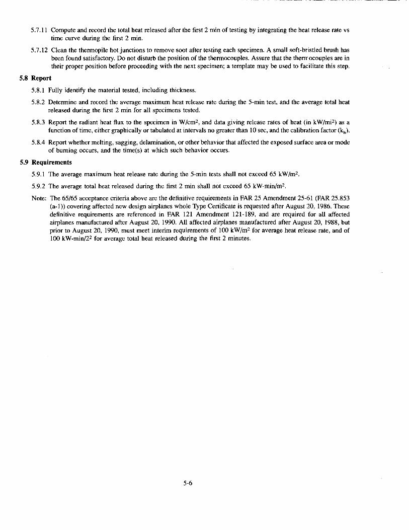
5. 7.11 Compute and record the total heat released after the first 2 min of testing by integrating the heat release rate vs time curve during the first 2 min.
5.7.12 Clean the thermopile hot junctions to remove soot after testing each specimen. A small soft-bristled brush has been found satisfactory. Do not disturb the position of the thermocouples. Assure that the thermocouples are in their proper position before proceeding with the next specimen; a template may be used to facilitate this step.
5.8 Report
5.8.1 Fully identify the material tested, including thickness.
5.8.2 Determine and record the average maximum heat release rate during the 5-min test, and the average total heat released during the first 2 min for all specimens tested.
5.8.3 Report the radiant heat flux to the specimen in W/cm2, and data giving release rates of heat (in kW/mi2) as a function of time, either graphically or tabulated at intervals no greater than 10 sec, and the calibmtion factor (kh).
5.8.4 Report whether melting, sagging, delamination, or other behavior that affected the exposed surface area or mode of burning occurs, and the time(s) at which such behavior occurs.
5.9 Requirements
5.9.1 The average maximum heat release rate during the 5-min tests shall not exceed 65 kW/m2.
5.9.2 The average total heat released during the first 2 min shall not exceed 65 kW-min/m2.
Note: The 65/65 acceptance criteria above are the definitive requirements in FAR 25 Amendment 25-61 (FAR 25.853 (a-1)) covering affected new design airplanes whole Type Certificate is requested after August 20, 1986. These definitive requirements are referenced in FAR 121 Amendment 121-189, and are required for all affected airplanes manufactured after August 20, 1990. All affected airplanes manufactured after August 20, 1988, but prior to August 20, 1990, must meet interim requirements of 100 kW/m2 for average heat release rate, and of 100 kW-min/22 for average total heat released during the first 2 minutes.
5-6
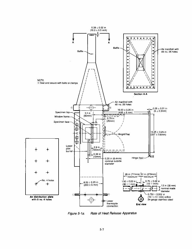
0.39 ± 0.02 in (10.0 ± 0.5 mm)
j_
r--.-T~ A
NOTE CD Seal and secure with bolts or clamps
+ +
+ +
+ +
Specimen top
Window frame
Specimen face
Lower pilot burner
-¥No.~oles
CD Air distribution plate
with 8 no. 4 holes
* 6~
' '
A
Baffle
Air manifold with 48 no. 26 holes
11
11 (20mm) 1
II I
1~// I -- // I - / "-'~>'A--+--+- II _- -... , H1nged flap
I I ' II '
l11 \ Ill \
t39 . l11 I . Ill~ I
100mm)' =--.:::::-=-=----=~ 0.39 in
Section A-A
(10mm) 1---'----'-t- 0.25 in (6.4mm) Hinge (typ)
nominal outside diameter
l
Air manifold with 48 no. 26 holes
13.25 ± 0.25 in
]±06mm)
8.00 ± 0.25 in (203 ± 6 mm)
L 28 io (711mj~' '"· (279mm)l lm1mmum m1mmumj
1.50 ± 0.03 in I+ 0. 75 ± 0.02 in
(38±1~m) (19±1m~) 1.5in(38mm) f--A -f- o+-- GJ nominal inside
-Lower thermopile connection
End view
d1amoter 0.750 ± 0.002 in (19.1 ± 0.1 mm) orifice 24-gauge stainless steel
Figure 5-1 a. Rate of Heat Release Apparatus
5-7
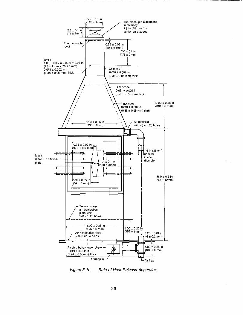
Thermocouple placement in chimney
Baffle
Thermocouple level-----"
--. 0.39 ± 0.02 in (10 ± 0.5mm)
1.2 in (30mm) from center on diagonal
7.0 ± 0.1 in (178 ± 3mm)
1.00 ± 0.03 in x 3.00 ± 0.03 in (25 ± 1 mm x 76 ± 1 mm) 0.018 ± 0.002 in
1 (0.38 ± 0.05 mm) thick
I I
I I
I
r---- -,-1 \
I \ I \
I \ I \
/ 1+-----13.0 ± 0.25 in
1 (330 ± 6mm) ---.j
2.00 ± 0.05 in (52± 1 mm)
I Second stage air distribution plate with
_ ~~0~~-~~h~='------ __ r 1
1
16.00 ± 0.25 in 1+----- (406 ± 6 mm) ----..J6.00 ± 0.25 in
Air distribution plate (152 ± 6 mm/ with 8 no. 4 holes
I
I Air distribution lower chamber 0.049 ± 0.002 in (1.24 ± 0.05mm) thick
Thermopile
12.20 ± 0.25 in (310 ± 6 mm)
31.0 ± 0.5 in (787 ± 12mm)
Figure 5-1 b. Rate of Heat Release Apparatus
5-8
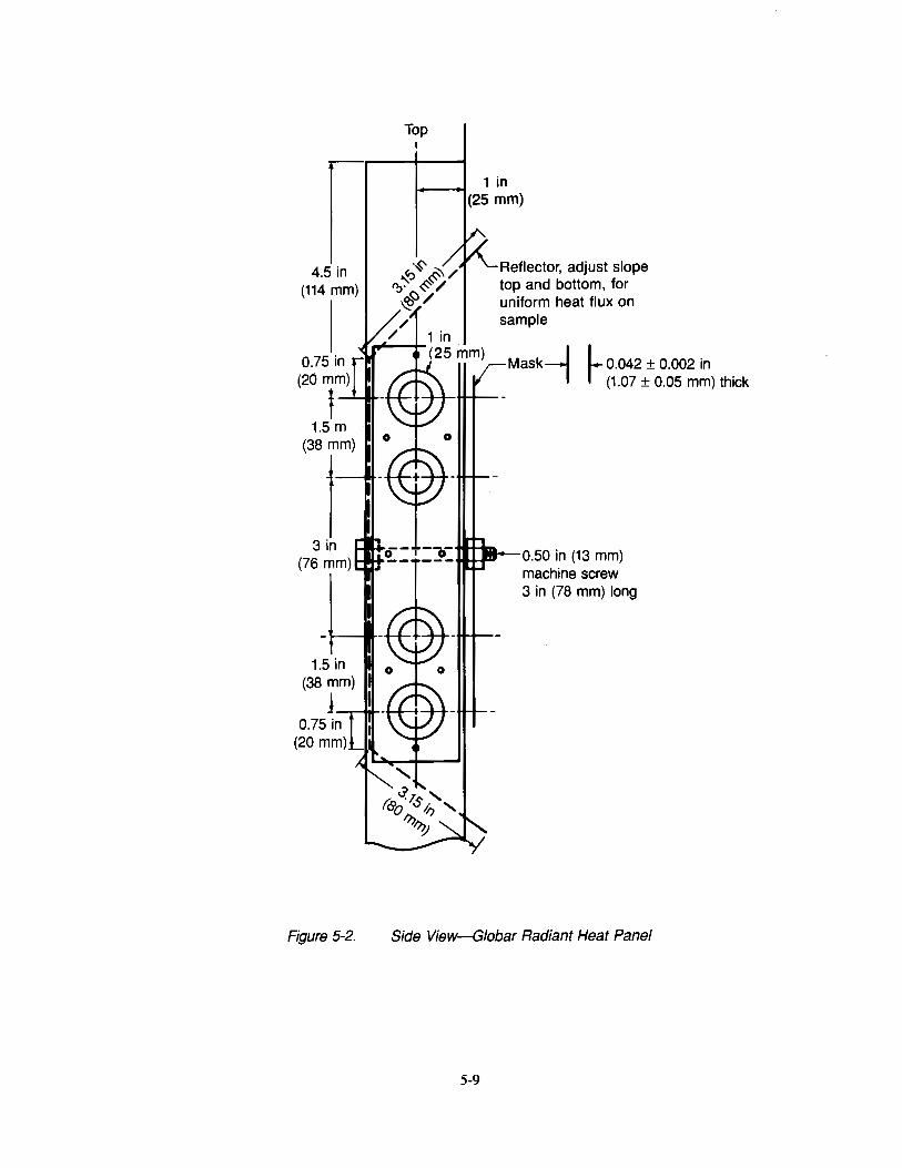
4.5 in (114 mm)
1.5 in (38 mm)
1-.---. ...
Figure 5-2.
Top I
1 in (25 mm)
Reflector, adjust slope top and bottom, for uniform heat flux on sample
Mask~ I_ 0.042 ± 0.002 in r (1.07 ± 0.05 mm) thick
0.50 in (13 mm) machine screw 3 in (78 mm) long
Side View-Giobar Radiant Heat Panel
5-9
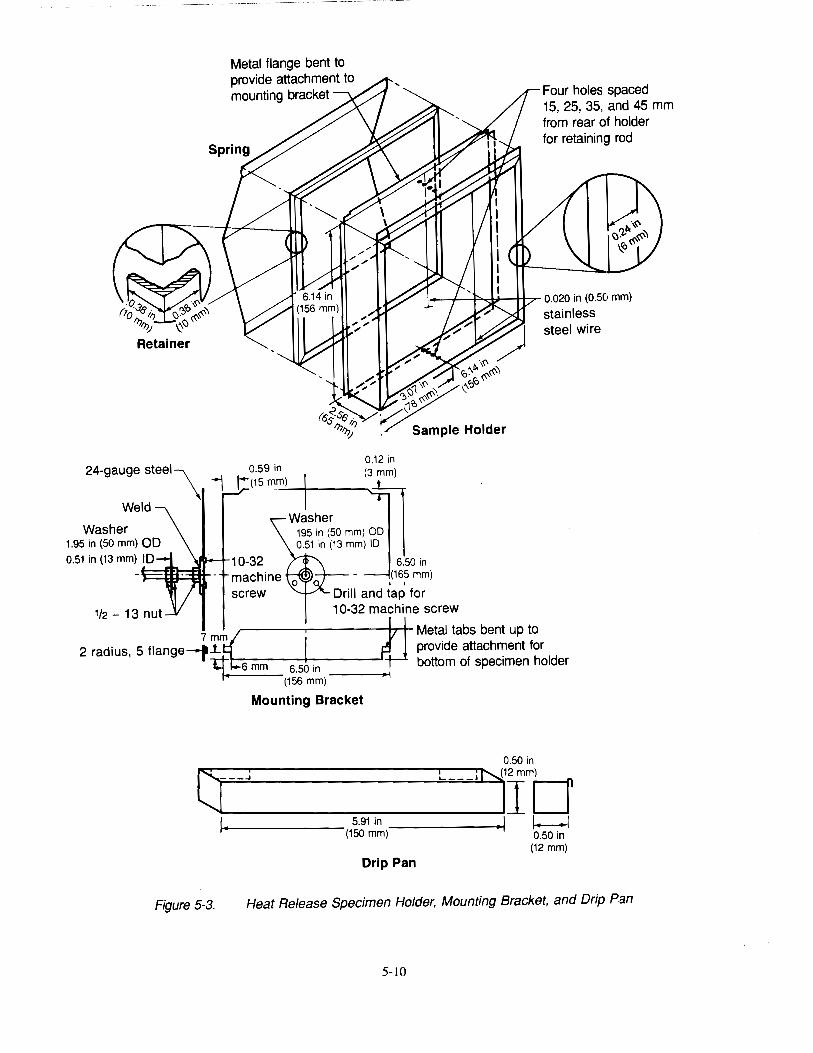
24-gauge steel\
Weld
Washer 1.95 in (50 mm) OD 0.51 in (13 mm) ID
Metal flange bent to provide attachment to mounting bracket Four holes spaced
15, 25, 35, and 45 mm from rear of holder for retaining rod
1--+----l~l::l----+11--:r- 0.020 in (0.50 mm)
0.59 in 0.12 in t: (15 m_m) (3 mm)
machine screw
~:~·~~ mm) :n 0.51 in (13 mm) 1~0 II
6.50 in (165 mm)
' Drill and tap for 10-32 machine screw
stainless steel wire
7 m& ~ Metal tabs bent up to 2 radius, 5 flange-pi. h provide attachment for
~1-:6:-m-m--6-.5+0-in ___ ---l bottom of spec1men holder
(156 mm)
Mounting Bracket
0.50 in
0~-J----~---L-J~IImtJ ~+--------- 5.91 in 1---1
(150 mm)------~ 0.50 in
(12mm) Drip Pan
Figure 5-3. Heat Release Specimen Holder, Mounting Bracket, and Drip Pan
5-lO

120v
.....L
CD R1
R1 CD Switch
® Transformer - 8 kVa Webster 812-6A-01 0
@Igniter -Auburn 1-20
@ Feed Through - Auburn F-140
R1 Relay - RH1 8-U, SH1 B-05
®
Figure 5-4. Lower Pilot Burner Igniter Schematic
5-11
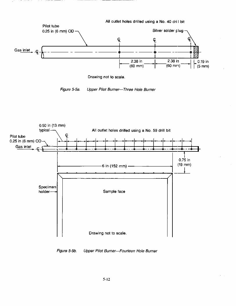
Pilot tube 0.25 in (6 mm) OD
Gas inlet -<t
Figure 5-5a.
All outlet holes drilled using a No. 40 drilll bit
Silver solder plug \
_: -- 1~ ----$---
L_ 2.38 in --·1~-+•-- 2.38 in _I L 0.19 in ~ (60 mm) (60 mnn) -I 1· (5 mm)
Drawing not to scale.
Upper Pilot Burner-Three Hole Burner
All outlet holes drilled using a No. 59 drill bit 0.50 in (13 mm)
typical~ Pilot tube <t Q25~~mm)oo~ l~j·~j·~j·~_·t ~·t· -~·t ·~~· ·~t ·t~· j·~j·~-~
Gas Inlet -<t 'i~-<•---------- 6 in (152 mm) ---------+1•1 Specimen holder--
~r---------------------------__,/
Sample face
Drawing not to scale.
Figure 5-5b. Upper Pilot Burner-Fourteen Hole Burner
5-12
0.75 in (19 mm)
l
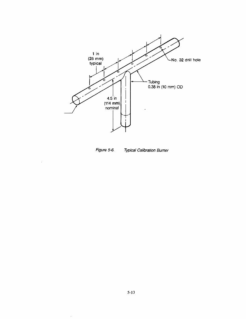
,__......._Tubing 0.38 in (10 mm) OD
Figure S-6. Typical Calibration Burner
5-13
This page intentionally left blank
5-14
Chapter 6 Smoke Test for Cabin Materials
6.1 Scope
6.1.1 This test method is used to determine the smoke generating characteristics of airplane passenger cabin interior materials using a Smoke Density Chamber.
6.1.2 This test method is used to demonstrate compliance with the requirements of FAR 25.853(a-l) through Amendment 25-66 and FAR 121.132 through Amendment 121-198.
6.2 Definitions
6.2.1 Specific Optical Density (D.)-Specific optical density is a dimensionless measure of the amount of smoke produced per unit area by a material when it is burned. In this test, the maximum value of Ds that occurs during the first four minutes of a test, 4Dm, is reported 1.
6.3 Test Apparatus
6.3.1 Required Equipment-The test chamber and related equipment (e.g., radiant heat furnace, heat flux density gauge, specimen holders, photometric system, multidirectional pilot burner, etc.) shall be as defined below:
6.3.1.1 Test Chamber-The test chamber shall be a square-cornered box with inside dimensions of 36.00 ± 0.13 in (914 ± 3 mm) width, 24.00 ± 0.13 in (610 ± 3 mm) depth, and 36.00 ± 0.13 in (914 ± 3 mm) height. A typical test chamber is shown in Figure 6-1. The location of size of items such as the chamber door, chamber controls, flowmeters, etc., is optional except as mandated in the following sections.
The interior surfaces (except for the chamber door, vents, etc.) shall be porcelain-enameled metaF, or equivalent coated metal that is resistant to chemical attack and corrosion, and suitable for periodic cleaning.
The chamber shall be equipped with a door such as indicated in Figure 6-1 to provide convenient access for changing test specimens, and for cleaning the chamber walls as required. The door shall have a viewing window3 to observe the chamber interior during a test, especially when any of the flamelets extinguish (see Section 6.7.2.11). The door shall have a seal so that when it is closed during tests, there will be no leakage of chamber contents. A small positive pressure can be developed and maintained inside the test chamber.
An inlet-outlet vent for pressure equalization shall be provided. The vent shall have a seal so that when it is closed during tests, there will be no leakage of chamber contents and a small positive pressure can be developed and maintained inside the test chamber.
6.3.1.2 Manometer-A device such as a manometer or pressure transducer shall be provided to monitor chamber pressure and leakage. The device shall have a range up to 6 in (152 mm) of water, and be connected to a suitable port in the test chamber wall.
6.3.1.3 Pressure Regulator-A pressure regulator shall be provided that consists of an open water-filled bottle and a piece of tubing, not to exceed 10 ft (305 em) in length, that has an inside diameter of at least 1 in (25 mm). One end of the tubing shall be connected to a sampling port on the top of the chamber; the other end of the tubing shall be held in position 4 in (102 mm) below the water surface.
lin most cases, the maximum specific optical density (4Dm) will be at 4 minutes; however, due to coagulation of smoke particles, or to absorption of smoke particles on the walls of the chamber, it is possible for the maximum to occur earlier in the test.
zcommercially available panels of porcelain-enameled steel (interior surface) permanently laminated to a magnesiainsulation core and backed with galvanized steel (exterior surface) have been found acceptable.
3A thin sheet of transparent material may be placed over optical and viewing windows to protect them against corrosive components in the smoke.
6-1

6.3.1.4 Test Chamber Wall Thermocouple-The temperature of the test chamber wall shall be monitored by a thermocouple suitable for measuring a temperature of 35°C. The thermocouple shall be mounted with its junction secured to the geometric center of the inner rear wall panel of the chamber using an electrically insulating disk cover.
6.3.1.5 Electric Power-650 W of 115 V, 60Hz, single phase electric powe~shall be provided for the radiant heat furnace and accessories. Where line voltage fluctuations exceed 2.5%, a constant voltage transformer shall be provideds.
6.3 .1.6 Radiant Heat Furnace-An electric furnace6 and associated controlling devices, such as shown in Figures 6-2 and 6-3, shall be provided that is capable of providing a constant thermal flux density of 2.50 ± 0.05 W/cm2 (2.20 ± 0.04 Btu/ft2/sec) on the specimen surface.
6.3 .1.6.1 Furnace Construction-The dimensions shown in Figure 6-2 for the elecltric furnace are critical. The furnace shall be located centrally along the long axis of the chamber with the opening facing toward and approximately 12 in (305 mm) from the right wall. The centerline of the furnace shall be approximately 7.75 in (197 mm) above the chamber floor.
6.3.1.6.2 Heating Element-The heating element? shall consist of a coiled wire capable of dissipating about 525 W. With the furnace installed, the heating element shall be positioned so that the coil loops are at the 12 o'clock position as shown in Figure 6-3.
6.3.1.6.3 Furnace Control System-The furnace control system shall be capable of controlling the radiant heat output at the required level of 2.50 ± 0.05 W/cm2 (2.20 ± 0.04 Btu/ft2/sec), as measured by the heat flux density gauge, under steady-state conditions with the chamber door closed for at least 5 minutes. The control system shall consist of an AC solid state voltage or power controllers and a voltmeter or other means for monitoring the electrical input.
6.3.1.6.4 Heat Flux Density Gauge-An air-cooled heat flux density gauge9 shall be provided for calibrating the output of the radiant heat furnace. The heat flux density gauge shall be a circular foil type, the operation of which was described by Gardon 10•
Compressed air at a pressure of 15 to 30 psi (0.10 to 0.21 MPa) shall be provided to cool the heat flux density gauge. The body temperature of the heat flux density gauge shall be monitored with a thermometer11 having an accuracy of 2°F (1 oq at 200°F (93°C) in a 0.50 by 0.50 by 1.50 in (13 by 13 by 38 mm) long brass or copper well drilled to accept the thermometer with a close fit. Silicone grease shall be used to provide good thermal contact. The circular receiving surface of the heat flux density gauge shall be spray-coated with an infrared-absorbing black paint. The heat flux density gauge shall be calibrated calorimetrically using a procedure that is acceptable to the FAA Administrator.
4A powerstat variable autotransformer, Type 21, from Superior Electric Co., Bristol, CT, or equivalent has been found satisfactory to transform electric power to that required by the chamber.
5A constant voltage transformer from Sola Electric Co., Chicago, II, catalog number 23-13-150 or eqUtivalent has been found satisfactory. A Sorenson Model 200S AC voltage regulator or equivalent has been found satisfactory.
6Furnace model PIN 6806025700 from Newport Scientific has been found acceptable.
7Heating element model PIN 68086022400 from Newport Scientific or equivalent has been found acceptable.
8A model470 Series Power controller manufactured by Eurotherm, a Model3AEV1Bl0Cl Triac manufactured by General Electric Co, or equivalent have been found satisfactory.
9The construction and operation of an acceptable heat flux density gauge may be found in ASTM F814-83.
10Gardon, R., "An Instrument for the-Direct Measurement oflntense Thermal Radiation," Review of Scientific Instruments, Vol. 24, 1953, pp. 360-370.
11 A thermocouple system capable of measuring 200 ± 2°F is an acceptable alternate method to monitor the body temperature of the heat flux density gauge.
6-2
6.3.1.7 Pilot Burner-The pilot burner shall be a multiple flamelet type with six tubes, as shown in Figure 6-4. The six tubes shall be fabricated from stainless steel tubing having an outer diameter of 0.125 in (3.2
mm) and on inner diameter of 0.055 in (1.4mm).:i0.001 in (0.025mm). The six tubes shall be attached to a common manifold, as shown in Figure 6-4, fabricated from stainless steel tubing having an outer diameter of 0.250 in (6.4 mm) and a wall thickness of 0.035 in (0.9 mm). One end of the manifold shall be closed, and the other end of the manifold be attached to a gas supply fitting on the chamber floor.
The two outer tubes of the pilot burner shall be directed perpendicular to the surface of the specimen. The two inner tubes shall be directed at an angle of 45 deg downward. The two intermediate tubes shall be directed vertically downward into the trough of the specimen holder.
The pilot burner shall be centered in front of and parallel to the specimen holder. The tips of the two outer tubes shall be placed 0.25 ± 0.06 in (6.4 ± 1.6 mm) above the lower opening of the specimen holder and 0.25 ± 0.03 in (6.4 ± 0.8 mm) away from the face of the specimen surface.
6.3.1.8 Pilot Burner Fuel-The gas fuel for the pilot burner shall be prepared by mixing filtered oil-free air with 95% minimum purity propane 12, and feeding the mixture to the pilot burner. Each gas shall be metered through separate, calibrated flowmeters and needle valves. The air-propane mixture shall consist of an air flow rate equivalent to 0.018 ± 0.001 ft3/min (500 ± 20 cm3/min) at standard temperature and pressure (STP), and a propane flow rate equivalent to 0.0018 ± 0.0001 ft3/min (50± 3 cm3/min) at STP. The compressed air supply shall be fed to its flowmeter at 20 ± 5 psi (0.14 ± 0.03 MPa), and the propane at 15 ± 3 psi (0.10 ± 0.02 MPa).
The visible parts of the pilot burner flamelets should be approximately 0.25 in (6 mm) long with a luminous inner cone approximately 0.13 in (3 mm) long, as shown in Figure 6-5. If the flame lets are not that approximate size, there is probably a difficulty with the air/propane fuel mixture and/or flow rate(s), in which case the accuracy of the flowmeters should be checked.
6.3.1.9 Specimen Holder-The specimen holder shall consist of a stainless steel frame, a backing made of insulation millboard, a spring and retaining rod to secure the specimen in place, and aluminum foil for wrapping the specimen.
6.3.1.9.1 Specimen Holder Frame-The specimen holder frame shall be fabricated of stainless steel sheet by bending and brazing (or spot welding) stainless steel sheet of 0.025 ± 0.002 (0.64 ± 0.05 mm) nominal thickness to conform in shape and dimension to Figure 6-6. The frame shall be at least 1.50 in (38 mm) deep, and shall provide an exposed specimen surface that is nominally 2.56 in by 2.56 (65 mm by 65 mm), and that is at least 6.50 in2 (4,194 mm2) in area.
A trough to catch and retain dripping material shall be attached to the bottom front of the holder.
Guides to permit accurate centering of the exposed specimen area in front of the furnace opening shall be attached to the top and bottom of the holder frame.
Two wires made of 0.020 ± 0.005 in (0.50 ± 0.12 mm) diameter stainless steel, vertically oriented and evenly spaced (0.85 in from the edge of the holder's vertical face openings, and 0.85 in from each other), shall be attached to the holder face 13 .
6.3.1.9.2 Specimen Backing-A piece of insulation millboard shall be used as a backing for the specimen and as a simulated blank specimen. The millboard 14 shall be nominally 0.50 in (13 mm) thick with a density of 50 ± 10 lb/ft3 (0.80 ± 0.16 g/cm3), or equivalent. Pieces shall be
t2Commercially bottled propane has been found acceptable.
l3Mounting the wire through holes made in the trough attachment mount between the top of the trough and the bottom of the holder, across the face of the specimen and over the top of the holder, and through holes made in the flange of the top guide just above the top of the holder, has been found satisfactory. This scheme permits the use of only one piece of wire, threaded through the four holes with the two ends twisted together behind the guide at the top of the holder.
t4A recommended material is Marinite I.
6-3
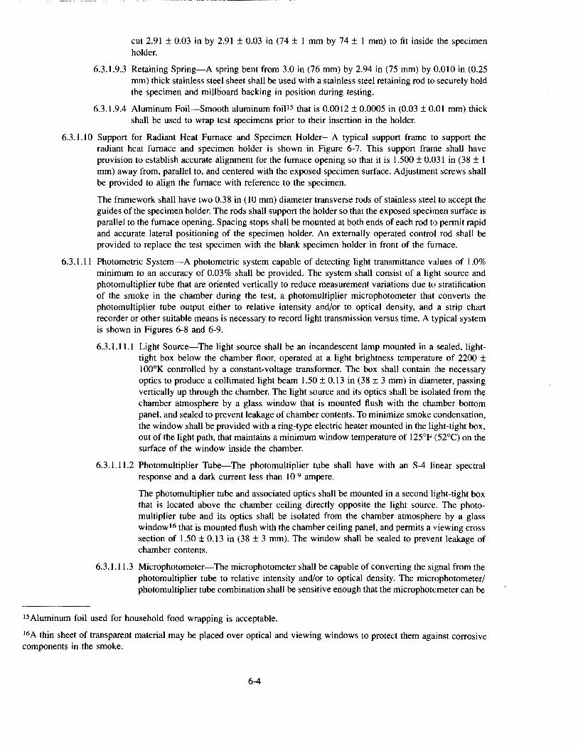
cut 2.9I ± 0.03 in by 2.9I ± 0.03 in (74 ± I mm by 74 ± I mm) to fit inside the specimen holder.
6.3.1.9.3 Retaining Spring-A spring bent from 3.0 in (76 mm) by 2.94 in (75 mm) by 0.010 in (0.25 mm) thick stainless steel sheet shall be used with a stainless steel retaining rod to securely hold the specimen and millboard backing in position during testing.
6.3.1.9.4 Aluminum Foil-Smooth aluminum foiP5 that is O.OOI2 ± 0.0005 in (0.03 ± O.OI mm) thick shall be used to wrap test specimens prior to their insertion in the holder.
6.3.1.1 0 Support for Radiant Heat Furnace and Specimen Holder-A typical support frame to support the radiant heat furnace and specimen holder is shown in Figure 6-7. This support frame shall have provision to establish accurate alignment for the furnace opening so that it is I.500 ± 0.03I in (38 ± I mm) away from, parallel to, and centered with the exposed specimen surface. Adjustment screws shall be provided to align the furnace with reference to the specimen.
The framework shall have two 0.38 in (I 0 mm) diameter transverse rods of stainless steel to accept the guides of the specimen holder. The rods shall support the holder so that the exposed specimen surface is parallel to the furnace opening. Spacing stops shall be mounted at both ends of each rod to permit rapid and accurate lateral positioning of the specimen holder. An externally operated control rod shall be provided to replace the test specimen with the blank specimen holder in front of the furnace.
6.3.I.II Photometric System-A photometric system capable of detecting light transmittance values of I.O% minimum to an accuracy of 0.03% shall be provided. The system shall consist of a light source and photomultiplier tube that are oriented vertically to reduce measurement variations due to stratification of the smoke in the chamber during the test, a photomultiplier microphotometer that converts the photomultiplier tube output either to relative intensity and/or to optical density, and a strip chart recorder or other suitable means is necessary to record light transmission versus time. A typical system is shown in Figures 6-8 and 6-9.
6.3.1.11.1 Light Source-The light source shall be an incandescent lamp mounted in a sealed, lighttight box below the chamber floor, operated at a light brightness temperature of 2200 ± 100°K controlled by a constant-voltage transformer. The box shall contain the necessary optics to produce a collimated light beam 1.50 ± 0.13 in (38 ± 3 mm) in diameter, passing vertically up through the chamber. The light source and its optics shall be isolated from the chamber atmosphere by a glass window that is mounted flush with the chamber bottom panel, and sealed to prevent leakage of chamber contents. To minimize smoke condensation, the window shall be provided with a ring-type electric heater mounted in the light-tight box, out of the light path, that maintains a minimum window temperature of I25°F {52°C) on the surface of the window inside the chamber.
6.3.1.11.2 Photomultiplier Tube-The photomultiplier tube shall have with an S-4 linear spectral response and a dark current less than IQ-9 ampere.
The photomultiplier tube and associated optics shall be mounted in a second light-tight box that is located above the chamber ceiling directly opposite the light source. The photomultiplier tube and its optics shall be isolated from the chamber atmosphere by a glass window 16 that is mounted flush with the chamber ceiling panel, and permits a viewing cross section of I.50 ± O.I3 in (38 ± 3 mm). The window shall be sealed to prevent leakage of chamber contents.
6.3.I.II.3 Microphotometer-The microphotometer shall be capable of converting the signal from the photomultiplier tube to relative intensity and/or to optical density. The microphotometer/ photomultiplier tube combination shall be sensitive enough that the microphotometer can be
Is Aluminum foil used for household food wrapping is acceptable.
16A thin sheet of transparent material may be placed over optical and viewing windows to protect them against corrosive components in the smoke.
6-4
adjusted to produce a full-scale reading (100% relative light intensity, or optical density= 1) using the photomultiplier tube's response (output) to the light source when a filter of 0.5 or greater optical density is placed in the light path.
6.3.1.11.4 Alignment Fixture- The two optical windows and their housings shall be kept in alignment and spaced 36.000 ± 0.125 in (914 ± 3 mm) apart with an alignment fixture consisting of three metal rods, 0.50 - 0. 75 in ( 13 - 19 mm) in diameter fastened securely to 0.31 in (8 mm) thick externally mounted top and bottom plates and symmetrically arranged about the collimated light beam.
6.3.1.11.5 Optical Filters-A set of nine neutral color optical filters 17-0.1, 0.2, 0.3, 0.4, 0.5, 0.6, 0.7, 0.8, and 0.9 optical density-shall also be provided. The optical filters, one or more as required, may be mounted in the light path in the optical measuring system to compensate for the sensitivity of the photomultiplier tube. These filters may also be used to adjust the photometric system as the light source and/or photomultiplier tube change sensitivity through aging, and/or as discoloration or deterioration of the optical windows occurs.
6.3.1.11.6 Recorder-A recording device shall be furnished that provides a record of the percent light transmission and/or optical density versus time during the test. The record shall consist either of a continuous curve on a chart recorder or discrete values taken at least every 5 seconds with a computerized data acquisition system.
6.3.1.12 Exhaust Hood-A method for removing the chamber contents after each test shall be provided. A fitting for removing the chamber contents may be connected to a suitable exhaust hood. Locating an exhaust hood directly above the smoke chamber door is recommended as an additional safety device.
6.3.1.13 Conditioning Chamber-A conditioning chamber capable of maintaining test specimens at a temperature of 70 ± 5°F (21 ± 3°C) and 50± 5% relative humidity shall be provided.
6.3.2 Recommended Equipment-The following items are recommended, but not required:
6.3.2.1 Digital Voltmeter-Preferred to monitor furnace voltage and heat flux density gauge output. A Keithley Model 165 Autoranging Multimeter or equivalent is acceptable.
6.3.2.2 Constant Voltage Transformer-A constant voltage transformer is recommended for all installations. See Section 6.3.1.5.
6.3.2.3 Pilot Burner Positioning Fixture-A fixture to accurately position the pilot burner is recommended to establish a precise pilot burner position for testing, and to facilitate accurate repositioning of p:ilot burner after removal and replacement.
6.3.2.4 Automated Igniter System-An automated igniter system is recommended to relight the horizontal and 44 deg pilot burner flamelets to ensure that none of them extinguishes for more than 3 seconds during the test.
6.4 Test Specimen Selection and Preparation
6.4.1 Specimen Number-A minimum of three specimens shall be prepared and tested for each part/construction.
6.4.2 Specimen Selection-Specimens shall either be taken from an actual part or built to simulate a part.
Flat sections of the same thickness and composition may be tested in place of curved, molded, or specialty parts.
Both faces of a multilayer assembly shall be tested as a separate part/construction if the outer materials are different on the faces, and if both sides are exposed to the passenger cabin interior. If both faces must be tested, two sets of specimens shall be provided.
17The accuracy these filters when used with the light source needs to be assured.
6-5

6.4.3 Specimen Size-Each specimen shall be 2.90 ± 0.06 in by 2.90 ± 0.06 in (73 ± 2 mm by 73 ± 2 mm).
The specimens shall be the same thickness as the thickness of the part/construction up to 1.0 in (25 mm); specimens from constructions thicker than 1 in (25 mm) shall be sliced to 1.0 in (25 mm) thickness and the uncut surface tested.
6.4.4 Specimen Orientation-For materials that may have anisotropic flammability properties (i.e. different properties in different directions, such as machine and cross-machine directions for extrusions, warp and fill directions of a woven fabric, etc.), specimens shall be tested in the orientation thought to give the highest result. If the 4Dm is greater than 180, a second set of specimens shall be prepared and tested in the orientation that is perpendicular to the orientation used for the first set of specimens. The higher of the two average 4Dm values shall be reported.
6.4.5 Specimen Preparation-All surfaces of the specimen, except the surface to be exposed for the test, shall be wrapped with aluminum foil (see Section 6.3.1.9.4) prior to placing them in a specimen holder. The side of the foil with dull finish shall be placed next to the specimen. After the specimen is placed in a specimen holder, any aluminum foil on the exposed specimen shall be removed from the bottom (to avoid interference with the pilot burner flamelets), and either removed or folded back on the other three sides (to avoid covering any of the exposed specimen surface area). The specimen shall be placed in a holder, followed by an alumina-silica backing board, the spring plate, and the retaining rod. See Figure 6-6.
6.5 Specimen Conditioning
6.5.1 Specimens shall be conditioned at a temperature of 70 ± 5°F (21 ± 3°C) and 50± 5% relative humidity for a minimum of 24 hours unless otherwise specified. Only one specimen at a time shall be removed from the conditioning chamber; when removed the specimen shall be immediately tested.
6.6 Test Chamber Calibration
6.6.1 Furnace Protection-Prepare a blank specimen cons1stmg of one-half inch thick alumina-silica millboard mounted in a specimen holder (see Section 6.3.1.9.2). To reduce problems with the stability of the heat flux density from the furnace, maintain the blank specimen in front of the furnace when no testing or calibration is being conducted.
6.6.2 Periodic Calibration Procedure-Conduct a periodic calibration of the system as follows:
6.6.2.1 Photometric System-The photometric system used in this test method is an inherently linear device. Check the system for proper photocell alignment. Verify, at least every two months, the linearity of the system using set of neutral optical density filters, or equivalent. If erratic behavior is observed or suspected, check the system more frequently.
6.6.2.2 Furnace-Use the approved heat flux density gauge to monitor the heat flux density produced by the furnace. Place the heat flux density gauge on the horizontal rods of the furnace support framework and accurately position it in front of the furnace opening by sliding and displacing the blank specimen holder against the spacing stop (see Section 6.3.1.1 0). With the chamber door closed and the inlet vent opened, adjust the compressed air supply to the heat flux density gauge cooler to maintain its body temperature at 200 ± 5°F (93 ± 3°C). Adjust the setting of the furnace control voltage or power controller to obtain the calibrated millivolt output of the heat flux density gauge corresponding to a steady-state irradiance of 2.50 ± 0.05 W/cm2 (2.20 ± 0.04 Btu/ft2/sec). After the irradiance has reached the required value and has remained steady-state for at least 5 minutes, remove the heat flux density gauge from the chamber and replace it with the blank specimen holder.
Record the setting of the furnace control voltage or power controller, and use this setting until a future calibration indicates it should be changed.
6.6.2.3 Chamber Leak Test-Test the smoke density chamber leak rate at least once a month, or more often if loss of chamber pressure is suspected, using the following procedure:
6.6.2.3.1 Place the heater switch in the OFF position. Close the inlet vent and the chamber door.
6-6
6.6.2.3.2 Pressurize (e.g., by bleeding in a small amount of air through the port used for the heat flux density gauge) the chamber to at least 3 inches of water above ambient as indicated by the manometer.
6.6.2.3.3 Note the chamber pressure. Verify that the chamber pressure leakage rate is less than 2 inches of water in 2 minutes.
6.6.2.4 Total System-Check the total system at least once a month by testing a material that has shown a consistent specimen-to-specimen 4Dm value in the range of 150 to 220, and that is and will continue to be readily available. Maintain a record of the test results obtained; if erratic values are observed, identify and correct any instrumental or operational deficiencies.
6.6.3 Chamber Cleaning-Clean the optical system windows, viewing window, chamber walls, and specimen holders as follows:
6.6.3.1 Optical System Windows-Clean the exposed surfaces of the glass separating the photo detector and light source housings from the interior of the chamber after each test. Clean the top window first, then the bottom window using a non-abrasive cloth dampened with a suitable cleaner's. Dry the window to prevent streaking or film buildup. Do not use any cleaners that contain wax because wax will cause the smoke to adsorb to the glass more quickly.
6.6.3.2 Viewing Window-Clean the viewing window periodically as required to allow viewing the chamber interior during testing. The same cleaners used in Section 6.6.3.1 have been found satisfactory.
6.6.3.3 Chamber Walls-Clean the chamber walls periodically to prevent excessive build-up of smoke products. An ammoniated spray detergent and non-abrasive scouring pad have been found effective.
6.6.3.4 Specimen Holders-Remove any charred residues on the specimen holders and horizontal rods securing the holder position to prevent contamination of subsequent specimens.
6.7 Test Procedure
6.7.1 Each day, prior to testing, adjust the chamber as follows:
6.7.1.1 Calibrate the furnace output according to Section 6.6.2.2 to determine the correct furnace voltage.
6.7.1.2 Balance the photomultiplier dark current, and set the clear beam reading to 100% relative transmission or to optical density 1.00'9.
6.7.2 Conduct the test procedure as follows:
6.7.2.1 Assure the specimen(s) have been properly prepared per Sections 6.4.1-6.4.5.
6.7.2.2 Assure the chamber wall temperature is 95 ± 4°F (35 ± 2°C).
6.7.2.3 Assure the furnace voltage has been set correctly.
6.7.2.4 Set the clear beam reading to 100% relative transmission or to optical density 1.00. See Section 6.7.1.2.
6.7.2.5 Position the pilot burner in front of and parallel to the specimen holder. Tum on the pilot burner fuel (see Section 6.3.1.8) and light the ftamelets on the pilot burner. Make sure all ftamelets are ignited and properly adjusted.
6.7.2.6 Remove a test specimen from the conditioning chamber, open the test chamber door, and place the specimen holder on the support. Immediately push the specimen holder into position in front of the furnace, displacing the blank specimen holder to the prepositioned stop, and close the chamber door and inlet vent. For chambers with an external device to move the specimen holder in front of the furnace, place the holder on the support, close the door, and then slide the sample into position.
1BEthyl alcohol, ethyl ketone, or equivalent have been found satisfactory.
19This procedure is described in AMINCO NBS Smoke Density Chamber, Catalog No. 4-5800B, Instruction 941B.
6-7

6.7.2.7 Place the specimen holder into position in front of the furnace, and simultaneously start the timer and recorder for light transmission.
6.7.2.8 Continue the test for a minimum of 4 minutes (240 sec). Do not perform any analysis of the chamber contents, such as gas sampling, during the first 4 minutes (240 sec) of testing.
6.7.2.9 Record the percent light transmission and/or optical density versus time (minutes) during the test.
6. 7 .2.1 0 Monitor the chamber pressure during the test. If negative pressure (below ambknt atmospheric) develops, open the inlet valve slightly to relieve pressure.
6. 7 .2.11 Monitor the pilot burner flame lets during the test. Note and record whether either of the outer ftamelets oriented perpendicular to the specimen surface, or if either of the inner ftamelets oriented 45° to specimen surface extinguishes and remains continuously extinguished for more than 3 seconds. If such extinguishing occurs, the test results from that specimen are not valid, and the test may be terminated and another test started with a new test specimen.
6. 7 .2.12 At the termination of the test, remove the test specimen holder from its position in front of the furnace and replace it with the blank specimen holder, using the exterior control rod. Begin exhausting the chamber of smoke within 1 minute by opening the door20 and the inlet vent (and exhaust vent, if used).
6. 7 .2.13 Continue to exhaust the chamber until all smoke has been removed.
6. 7 .2.14 Clean the windows to the housings for the photomultiplier tube and the light source per Section 6.6.3.1.
6.7.2.15 Calculate and record the maximum specific optical density, 4Dm, during the 4-minute (240-sec) test for each specimen according to the formula:
where:
4Dm =(VILA) Log10(100/4Tm) = 132Log10(100/4Tm)
V =chamber volume= 18.00 ft3 (0.510 m3) L =light path length= 3.00 ft (0.914 m) A =exposed specimen area= 6.57 in2 (0.00424 m2) 4T m = minimum percent light transmission during 4 minutes Log 10(1 00/4T m) = maximum optical density during 4 minutes
6.7.2.16 Calculate and record the average 4Dm value and its standard deviation for all the specimens tested for each part/construction. Use the actual 4Dm values for this average; do not use the average light transmission value to determine the average 4Dm value.
6.8 Report
6.8.1 Report a complete identification of the part/construction tested, such as material construction, thickness, weight, etc.
6.8.2 Report the number of specimens tested, the average 4Dm.
6.8.3 Report any additional data or observations, as applicable and/or required by the test plan.
6.9 Requirements
6.9.1 Through FAR 25.853(a-1) Amendment 25-66, the average 4Dm during the 4 minute test shall not exceed 200.
2°CAUTION: The door should be opened gradually to avoid exposure to the chamber contents that may be toxic.
6-8
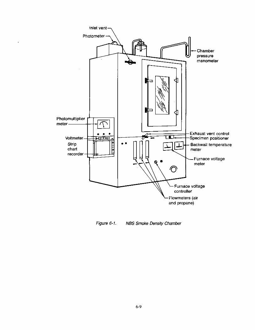
Photomultiplier rr;:::::::=~ meter----+-+~
• • • Voltmeter--f~~~~~
Strip chart recorder L~~====:lj
Chamber pressure manometer
L---~~~~==nn:=::::t Exhaust vent control L..JI~t-----t-Specimen positioner
• • Backwall temperature meter
Furnace volta~~e meter
....... 1-----~~[~\::F:u~rn=alce voltage
Figure 6-1.
controller
Flowmeters (air and propane)
NBS Smoke Density Chamber
6-9
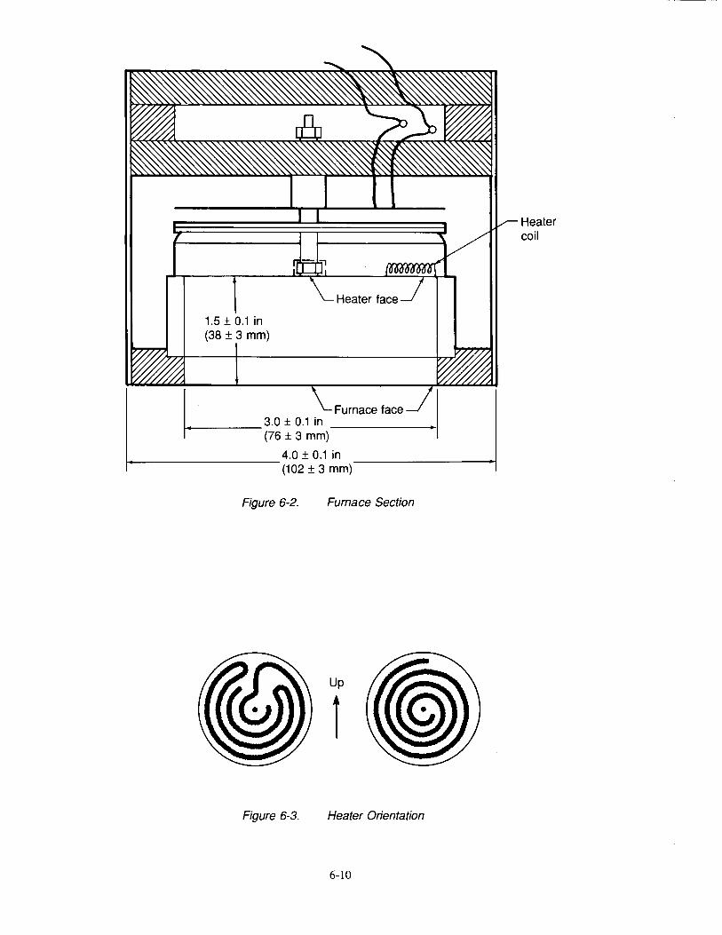
1.5 ± 0.1 in (38 ± 3 mm)
~---------4.0 ± 0.1 in (102 ± 3 mm)
Figure 6-2. Furnace Section
Up
1
Figure 6-3. Heater Orientation
6-10
Heater coil
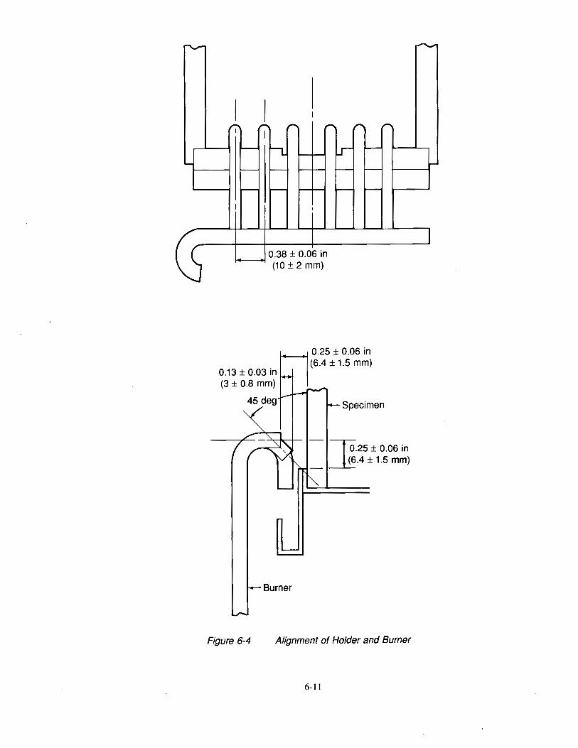
0.38 ± 0.06 in t-----+1
(10 ± 2 mm)
Figure 6-4
Burner
Specimen
- Jo.25 ± 0.06 in ~.4 ± 1.5 mm)
Alignment of Holder and Burner
6-11
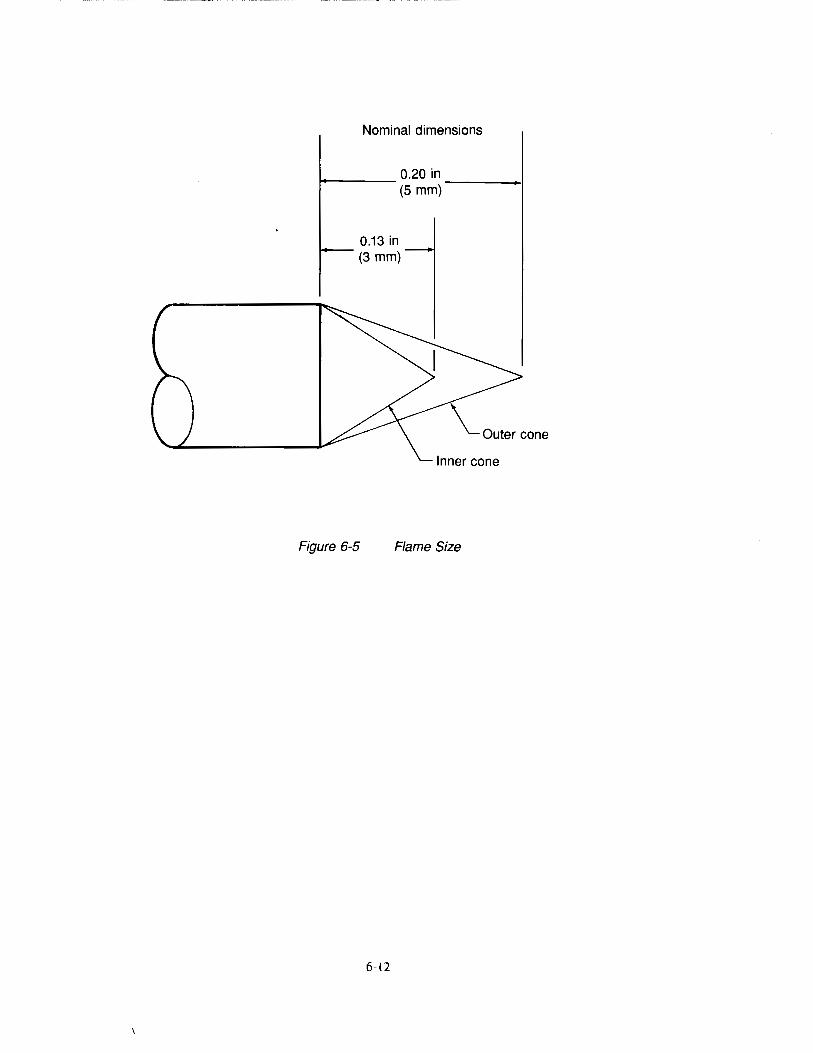
Nominal dimensions
..,...._ ____ 0.20 in ----~ (5 mm)
0.13 in (3 mm)
\_Outer cone
Figure 6-5 Flame Size
6-12
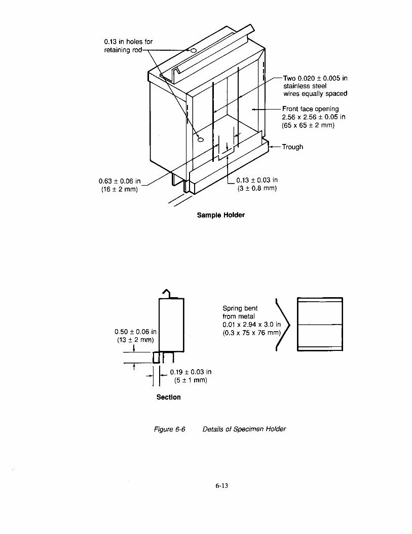
0.63 ± 0.06 in (16 ± 2 mm)
Two 0.020 ± 0.005 in stainless steel wires equally spaced
-++-+-- Front face opening
0.13 ± 0.03 in (3 ± 0.8 mm)
2.56 x 2.56 ± 0.05 in (65 x 65 ± 2 mm)
Trough
Sample Holder
0.50 ± 0.06 in (13 ± 2 mm)
!
t J L 0.19 ± 0.03 in -, r (5 ± 1 mm)
Section
Spring bent from metal 0.01 X 2.94 X 3.0 in (0.3 x 75 x 76 mm)
Figure 6-6 Details of Specimen Holder
6-13
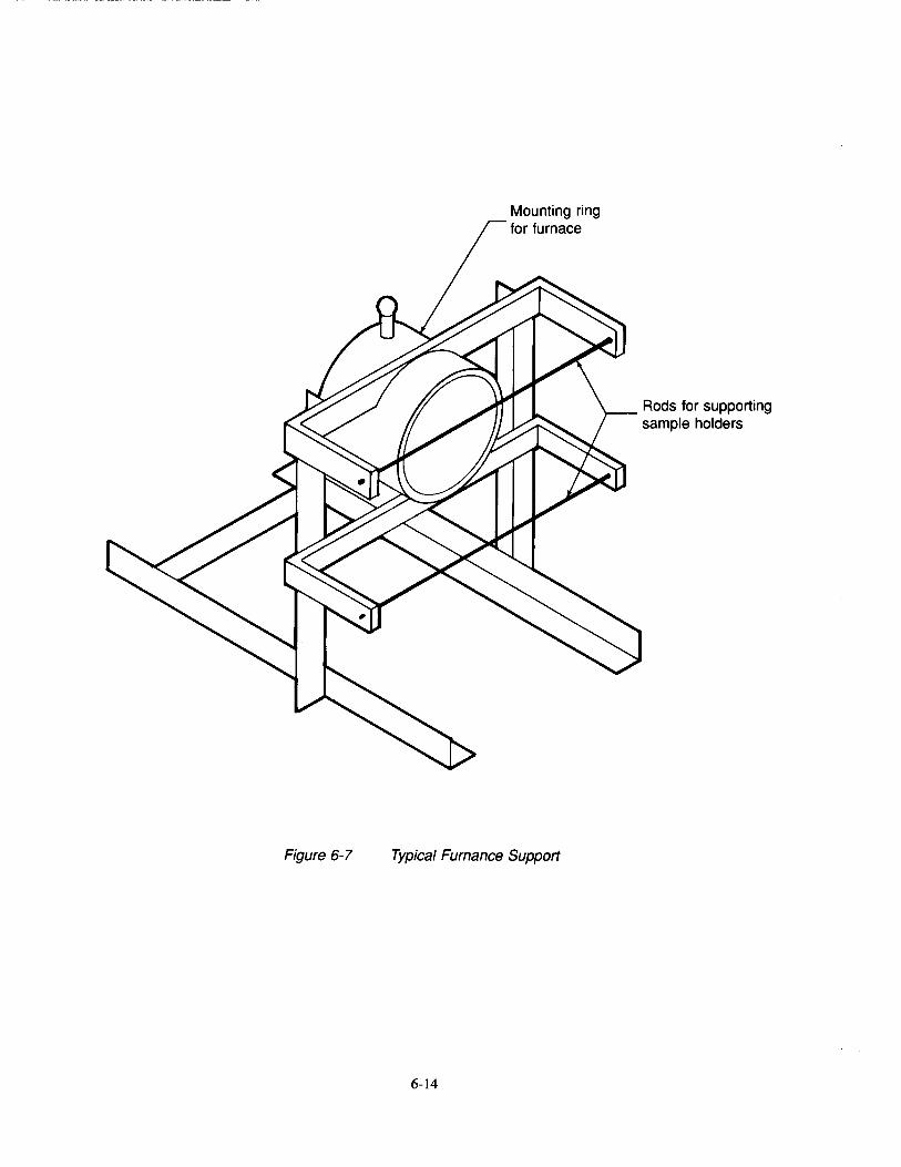
Figure 6-7
Mounting ring for furnace
Typical Furnance Support
6-14
Rods for supporting sample holders
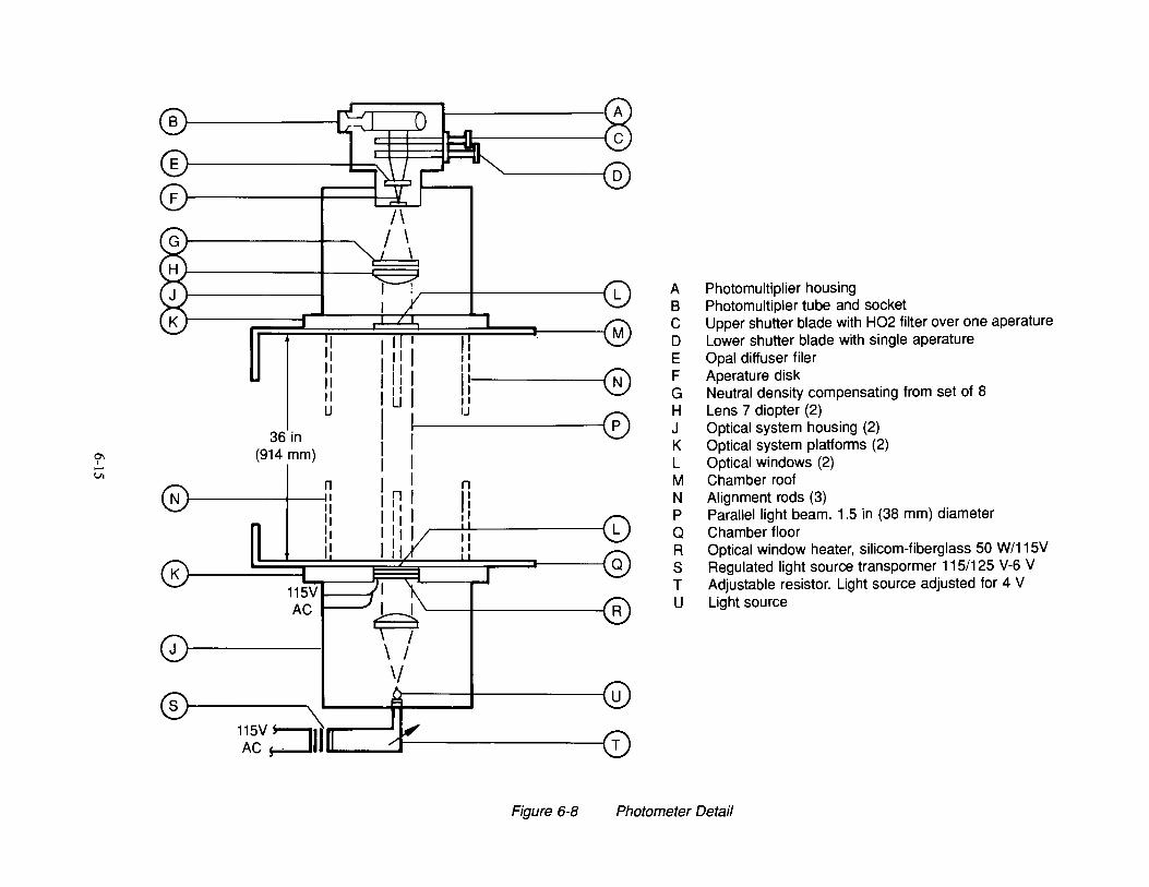
a-. I -Vl
B J----------1
36in (914 mm)
I ~ II II II u
'------;o
'I II ~ II u ,, (P)
n II ,I
N
'--+------4 R
0r-----~ .Y I lU
11~v :::JIIlLII _....::::dJ-----------1
A Photomultiplier housing B Photomultipler tube and socket C Upper shutter blade with H02 filter over one aperature D Lower shutter blade with single aperature E Opal diffuser filer F Aperature disk G Neutral density compensating from set of 8 H Lens 7 diopter (2) J Optical system housing (2) K Optical system platforms (2) L Optical windows (2) M Chamber roof N Alignment rods (3) P Parallel light beam. 1.5 in (38 mm) diameter Q Chamber floor R Optical window heater, silicom-fiberglass 50 W/115V S Regulated light source transpormer 115/125 V-6 V T Adjustable resistor. Light source adjusted for 4 V U Light source
Figure 6-8 Photometer Detail
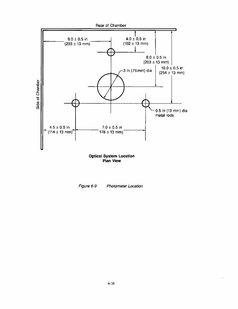
..... Q) .0 E tU ~ () -0 Q) "0 U5
8.0 ± 0.5 in (203 ± 13 mm)
Rear of Chamber
4.0 ± 0.5 in (102 ± 13 mm)
8.0 ± 0.5 in (203 ± 13 mm)
4.5 ± 0.5 in ... (114 ± 13 mm)
3 in (76 mm) dia
7.0 ± 0.5 in 178 ± 13 mm)-----1
Optical System Location Plan View
Figure 6-9 Photometer Location
6-16
10.0 ± 0.5 in (254 ± 13 mm)
0.5 in (13 mm) dia metal rods
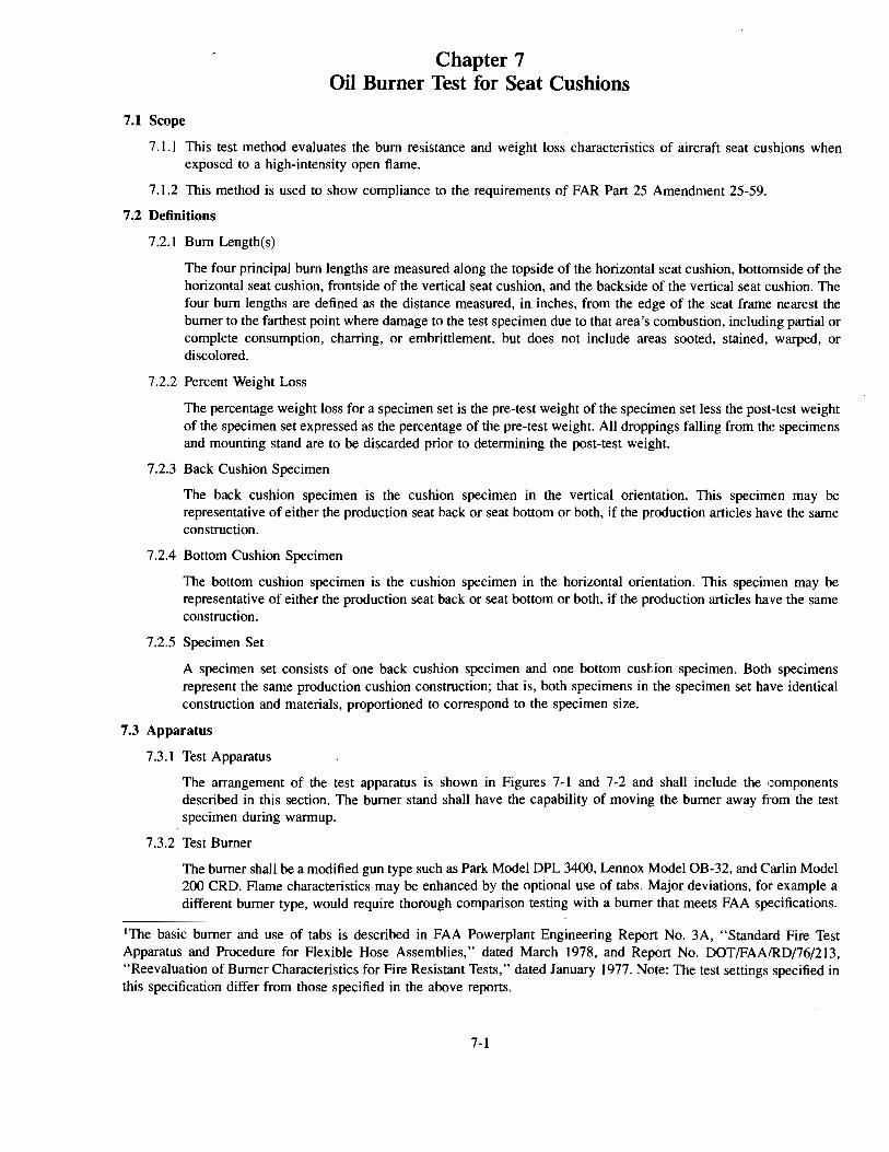
Chapter 7 Oil Burner Test for Seat Cushions
7.1 Scope
7 .1.1 This test method evaluates the bum resistance and weight loss characteristics of aircraft seat cushions when exposed to a high-intensity open flame.
7.1.2 This method is used to show compliance to the requirements of FAR Part 25 Amendment 25-59.
7.2 Definitions
7.2.1 Bum Length(s)
The four principal bum lengths are measured along the topside of the horizontal seat cushion, bottomside of the horizontal seat cushion, frontside of the vertical seat cushion, and the backside of the vertical seat cushion. The four bum lengths are defined as the distance measured, in inches, from the edge of the seat frame nearest the burner to the farthest point where damage to the test specimen due to that area's combustion, including partial or complete consumption, charring, or embrittlement, but does not include areas sooted, stained, warped, or discolored.
7 .2.2 Percent Weight Loss
The percentage weight loss for a specimen set is the pre-test weight of the specimen set less the post-test weight of the specimen set expressed as the percentage of the pre-test weight. All droppings falling from the specimens and mounting stand are to be discarded prior to determining the post-test weight.
7.2.3 Back Cushion Specimen
The back cushion specimen is the cushion specimen in the vertical orientation. This specimen may be representative of either the production seat back or seat bottom or both, if the production articles have the same construction.
7 .2.4 Bottom Cushion Specimen
The bottom cushion specimen is the cushion specimen in the horizontal orientation. This specimen may be representative of either the production seat back or seat bottom or both, if the production articles have the same construction.
7 .2.5 Specimen Set
A specimen set consists of one back cushion specimen and one bottom cushion specimen. Both specimens represent the same production cushion construction; that is, both specimens in the specimen set have identical construction and materials, proportioned to correspond to the specimen size.
7.3 Apparatus
7.3.1 Test Apparatus
The arrangement of the test apparatus is shown in Figures 7-1 and 7-2 and shall include the components described in this section. The burner stand shall have the capability of moving the burner away from the test specimen during warmup.
7.3.2 Test Burner
The burner shall be a modified gun type such as Park Model DPL 3400, Lennox Model OB-32, and Carlin Model 200 CRD. Flame characteristics may be enhanced by the optional use of tabs. Major deviations, for example a different burner type, would require thorough comparison testing with a burner that meets FAA specifications.
1The basic burner and use of tabs is described in FAA Powerplant Engineering Report No. 3A, "Standard Fire Test Apparatus and Procedure for Flexible Hose Assemblies," dated March 1978, and Report No. DOT/FAAIRD/76/213, "Reevaluation of Burner Characteristics for Fire Resistant Tests," dated January 1977. Note: The test settings specified in this specification differ from those specified in the above reports.
7-1
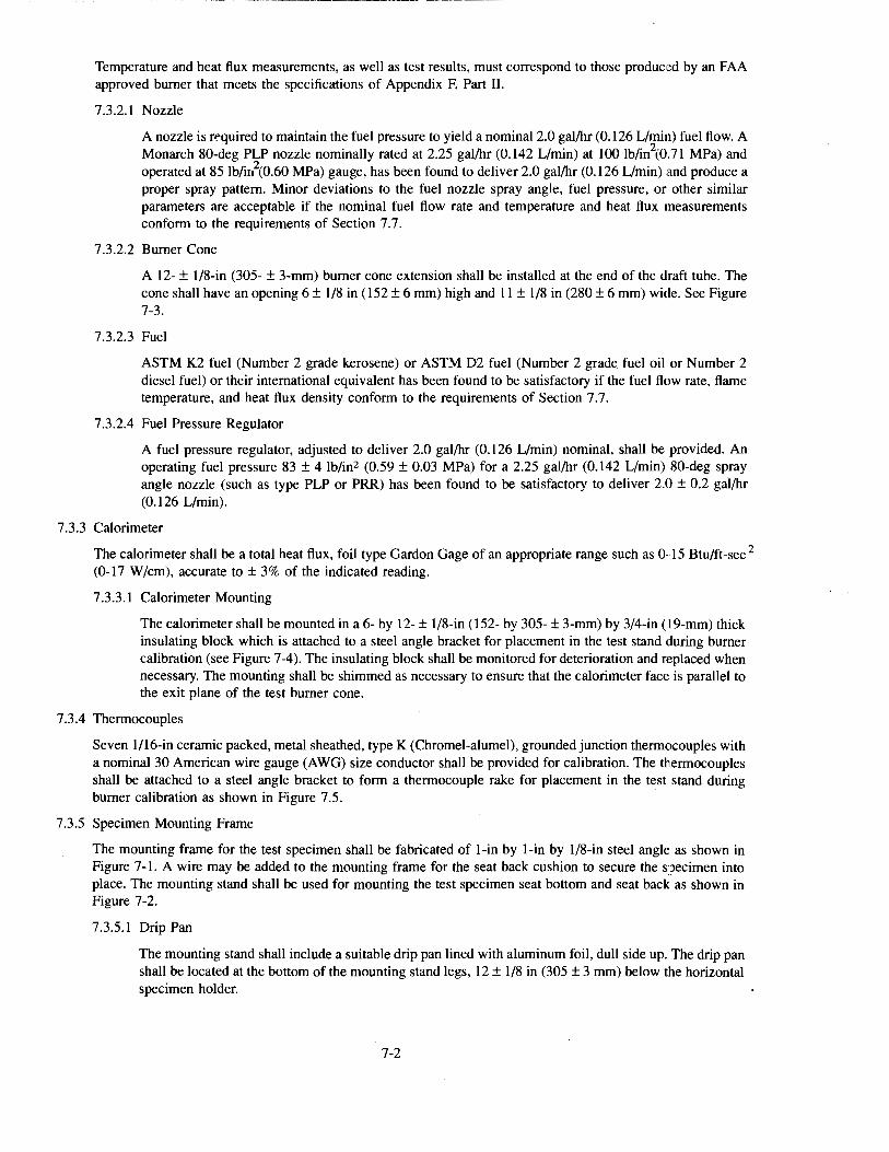
Temperature and heat flux measurements, as well as test results, must correspond to those produced by an FAA approved burner that meets the specifications of Appendix F, Part II.
7.3.2.1 Nozzle
A nozzle is rl:"quired to maintain the fuel pressure to yield a nominal2.0 gal/hr (0.126 L/min) fuel flow. A Monarch 80-deg PLP nozzle nominally rated at 2.25 gal/hr (0.142 L/min) at 100 lb/in2(0.71 MPa) and operated at 85 lb/ir?(0.60 MPa) gauge, has been found to deliver 2.0 gal/hr (0.126 L/min) and produce a proper spray pattern. Minor deviations to the fuel nozzle spray angle, fuel pressure, or other similar parameters are acceptable if the nominal fuel flow rate and temperature and heat flux measurements conform to the requirements of Section 7.7.
7.3.2.2 Burner Cone
A 12- ± 1/8-in (305- ± 3-mm) burner cone extension shall be installed at the end of the draft tube. The cone shall have an opening 6 ± 1/8 in (152 ± 6 mm) high and 11 ± 1/8 in (280 ± 6 mm) wide. See Figure 7-3.
7.3.2.3 Fuel
ASTM K2 fuel (Number 2 grade kerosene) or ASTM D2 fuel (Number 2 grade fuel oil or Number 2 diesel fuel) or their international equivalent has been found to be satisfactory if the fuel flow rate, flame temperature, and heat flux density conform to the requirements of Section 7.7.
7.3.2.4 Fuel Pressure Regulator
A fuel pressure regulator, adjusted to deliver 2.0 gal/hr (0.126 L/min) nominal, shall be provided. An operating fuel pressure 83 ± 4 lb/in2 (0.59 ± 0.03 MPa) for a 2.25 gal/hr (0.142 L/min) 80-deg spray angle nozzle (such as type PLP or PRR) has been found to be satisfactory to deliver 2.0 ± 0.2 gal/hr (0.126 L/min).
7.3.3 Calorimeter
The calorimeter shall be a total heat flux, foil type Gardon Gage of an appropriate range such as 0·15 Btu/ft-sec 2
(0-17 W /em), accurate to ± 3% of the indicated reading.
7 .3.3.1 Calorimeter Mounting
The calorimeter shall be mounted in a 6- by 12- ± 1/8-in (152- by 305- ± 3-mm) by 3/4-in ( 19-mm) thick insulating block which is attached to a steel angle bracket for placement in the test stand during burner calibration (see Figure 7-4). The insulating block shall be monitored for deterioration and replaced when necessary. The mounting shall be shimmed as necessary to ensure that the calorimeter face is parallel to the exit plane of the test burner cone.
7.3.4 Thermocouples
Seven l/16-in ceramic packed, metal sheathed, type K (Chromel-alumel), grounded junction thermocouples with a nominal 30 American wire gauge (AWG) size conductor shall be provided for calibration. The thermocouples shall be attached to a steel angle bracket to form a thermocouple rake for placement in the test stand during burner calibration as shown in Figure 7.5.
7.3.5 Specimen Mounting Frame
The mounting frame for the test specimen shall be fabricated of l-in by l-in by 1/8-in steel angle as shown in Figure 7-1. A wire may be added to the mounting frame for the seat back cushion to secure the specimen into place. The mounting stand shall be used for mounting the test specimen seat bottom and seat back as shown in Figure 7-2.
7.3.5.1 Drip Pan
The mounting stand shall include a suitable drip pan lined with aluminum foil, dull side up. The drip pan shall be located at the bottom of the mounting stand legs, 12 ± 1/8 in (305 ± 3 mm) below the horizontal specimen holder.
7-2
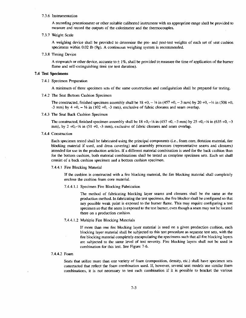
7.3.6 Instrumentation
A recording potentiometer or other suitable calibrated instrument with an appropriate range shall be provided to measure and record the outputs of the calorimeter and the thermocouples.
7.3.7 Weight Scale
A weighing device shall be provided to determine the pre- and post-test weights of each set of seat cushion specimens within 0.02 lb (9g). A continuous weighing system is recommended.
7.3.8 Timing Device
A stopwatch or other device, accurate to± 1%, shall be provided to. measure the time of application of the burner flame and self-extinguishing time (or test duration).
7.4 Test Specimens
7.4.1 Specimen Preparation
A minimum of three specimen sets of the same construction and configuration shall be prepared for testing.
7 .4.2 The Seat Bottom Cushion Specimen
The constructed, finished specimen assembly shall be 18 +0,- Ys in (457 +0,- 3 mm) by 20 +0, -Vl1 in (508 +0, -3 mm) by 4 +0,- Ys in (102 +0, -3 mm), exclusive of fabric closures and seam overlap.
7.4.3 The Seat Back Cushion Specimen
The constructed, finished specimen assembly shall be 18 +0,-Ys in (457 +0, -3 mm) by 25 +0,-Ys in (635 +0, -3 mm), by 2 +0,-Ys in (51 +0, -3 mm), exclusive of fabric closures and seam overlap.
7 .4.4 Construction
Each specimen tested shall be fabricated using the principal components (i.e., foam core, flotation material, fire blocking material if used, and dress covering) and assembly processes (representative seams and closures) intended for use in the production articles. If a different material combination is used for the back cushion than for the bottom cushion, both material combinations shall be tested as complete specimen sets. Each set shall consist of a back cushion specimen and a bottom cushion specimen.
7 .4.4.1 Fire Blocking Material
If the cushion is constructed with a fire blocking material, the fire blocking material shall completely enclose the cushion foam core material.
7.4.4.1.1 Specimen Fire Blocking Fabrication
The method of fabricating blocking layer seams and closures shall be the same as the production method. In fabricating the test specimen, the fire blocker shall be configured so that any possible weak point is exposed to the burner flame. This may require configuring a test specimen so that the seam is exposed to the test burner, even though a seam may not be located there on a production cushion.
7 .4.4.1.2 Multiple Fire Blocking Materials
7 .4.4.2 Foam
If more than one fire blocking layer material is used on a given production cushion, each blocking layer material shall be subjected to this test procedure as separate test sets, with the fire blocking material completely encapsulating the specimens such that all fire blocking layers are subjected to the same level of test severity. Fire blocking layers shall not be used in combination for this test. See Figure 7-6.
Seats that utilize more than one variety of foam (composition, density, etc.) shall have specimen sets constructed that reflect the foam combination used. If, however, several seat models use similar foam combinations, it is not necessary to test each combination if it is possible to bracket the various
7-3
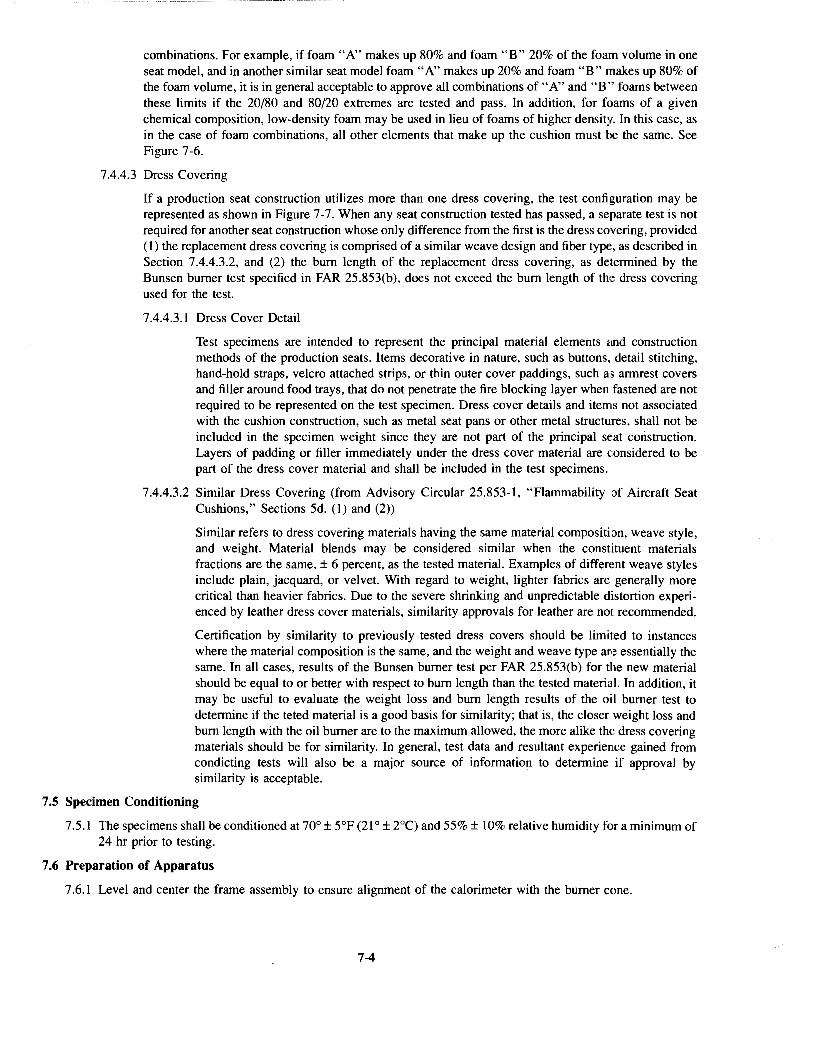
combinations. For example, if foam "A" makes up 80% and foam "B" 20% of the foam volume in one seat model, and in another similar seat model foam "A" makes up 20% and foam "B" makes up 80% of the foam volume, it is in general acceptable to approve all combinations of "A" and "B " foams between these limits if the 20/80 and 80/20 extremes are tested and pass. In addition, for foams of a given chemical composition, low-density foam may be used in lieu of foams of higher density. In this case, as in the case of foam combinations, all other elements that make up the cushion must be the same. See Figure 7-6.
7.4.4.3 Dress Covering
If a production seat construction utilizes more than one dress covering, the test configuration may be represented as shown in Figure 7-7. When any seat construction tested has passed, a separate test is not required for another seat construction whose only difference from the first is the dress covering, provided (I) the replacement dress covering is comprised of a similar weave design and fiber type::, as described in Section 7.4.4.3.2, and (2) the bum length of the replacement dress covering, as determined by the Bunsen burner test specified in FAR 25.853(b), does not exceed the bum length of the dress covering used for the test.
7.4.4.3.1 Dress Cover Detail
Test specimens are intended to represent the principal material elements c:md construction methods of the production seats. Items decorative in nature, such as buttons, detail stitching, hand-hold straps, velcro attached strips, or thin outer cover paddings, such as armrest covers and filler around food trays, that do not penetrate the fire blocking layer when fastened are not required to be represented on the test specimen. Dress cover details and items not associated with the cushion construction, such as metal seat pans or other metal structures, shall not be included in the specimen weight since they are not part of the principal seat cmistruction. Layers of padding or filler immediately under the dress cover material are considered to be part of the dress cover material and shall be included in the test specimens.
7.4.4.3.2 Similar Dress Covering (from Advisory Circular 25.853-1, "Flammability of Aircraft Seat Cushions," Sections 5d. (1) and (2))
Similar refers to dress covering materials having the same material composition, weave style, and weight. Material blends may be considered similar when the constituent materials fractions are the same, ± 6 percent, as the tested material. Examples of different weave styles include plain, jacquard, or velvet. With regard to weight, lighter fabrics are generally more critical than heavier fabrics. Due to the severe shrinking and unpredictable distortion experienced by leather dress cover materials, similarity approvals for leather are not recommended.
Certification by similarity to previously tested dress covers should be limited to instances where the material composition is the same, and the weight and weave type are essentially the same. In all cases, results of the Bunsen burner test per FAR 25.853(b) for the new material should be equal to or better with respect to bum length than the tested material. In addition, it may be useful to evaluate the weight loss and bum length results of the oil burner test to determine if the teted material is a good basis for similarity; that is, the closer weight loss and bum length with the oil burner are to the maximum allowed, the more alike th{: dress covering materials should be for similarity. In general, test data and resultant experience gained from condicting tests will also be a major source of information to determine if approval by similarity is acceptable.
7.5 Specimen Conditioning
7.5.1 The specimens shall be conditioned at 70° ± 5°F (21 o ± 2°C) and 55%± 10% relative humidity for a minimum of 24 hr prior to testing.
7.6 Preparation of Apparatus
7.6.1 Level and center the frame assembly to ensure alignment of the calorimeter with the burner cone.
7-4
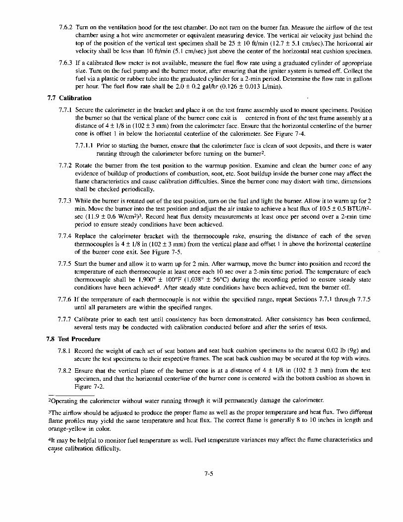
7 .6.2 Tum on the ventilation hood for the test chamber. Do not tum on the burner fan. Measure the airflow of the test chamber using a hot wire anemometer or equivalent measuring device. The vertical air velocity just behind the top of the position of the vertical test specimen shall be 25 ± 10ft/min (12.7 ± 5.1 cm/sec).The horizontal air velocity shall be less than 10ft/min (5.1 em/sec) just above the center of the horizontal seat cushion specimen.
7.6.3 If a calibrated flow meter is not available, measure the fuel flow rate using a graduated cylinder of appropriate size. Tum on the fuel pump and the burner motor, after ensuring that the igniter system is turned off. Collect the fuel via a plastic or rubber tube into the graduated cylinder for a 2-min period. Determine the flow rate in gallons per hour. The fuel flow rate shall be 2.0 ± 0.2 gal/hr (0.126 ± 0.013 L/min).
7.7 Calibration
7.7.1 Secure the calorimeter in the bracket and place it on the test frame assembly used to mount specimens. Position the burner so that the vertical plane of the burner cone exit is centered in front of the test frame assembly at a distance of 4 ± 1/8 in (I 02 ± 3 mm) from the calorimeter face. Ensure that the horizontal centerline of the burner cone is offset 1 in below the horizontal centerline of the calorimeter. See Figure 7-4.
7.7.1.1 Prior to starting the burner, ensure that the calorimeter face is clean of soot deposits, and there is water running through the calorimeter before turning on the bumer2.
7.7.2 Rotate the burner from the test position to the warmup position. Examine and clean the burner cone of any evidence of buildup of productions of combustion, soot, etc. Soot buildup inside the burner cone may affect the flame characteristics and cause calibration difficulties. Since the burner cone may distort with time, dimensions shall be checked periodically.
7.7.3 While the burner is rotated out of the test position, tum on the fuel and light the burner. Allow it to warm up for 2 min. Move the burner into the test position and adjust the air intake to achieve a heat flux of 10.5 ± 0.5 BTU/ft2-sec (11.9 ± 0.6 W/cm2)3. Record heat flux density measurements at least once per second over a 2-min time period to ensure steady conditions have been achieved.
7.7.4 Replace the calorimeter bracket with the thermocouple rake, ensuring the distance of each of the seven thermocouples is 4 ± 1/8 in (102 ± 3 mm) from the vertical plane and offset 1 in above the horizontal centerline of the burner cone exit. See Figure 7-5.
7.7.5 Start the burner and allow it to warm up for 2 min. After warmup, move the burner into position and record the temperature of each thermocouple at least once each 10 sec over a 2-min time period. The temperature of each thermocouple shall be 1,900° ± l00°F (1,038° ± 56°C) during the recording period to ensure steady state conditions have been achieved4. After steady state conditions have been achieved, tum the burner off.
7.7.6 If the temperature of each thermocouple is not within the specified range, repeat Sections 7.7.1 through 7.7.5 until all parameters are within the specified ranges.
7. 7. 7 Calibrate prior to each test until consistency has been demonstrated. After consistency has been confirmed, several tests may be conducted with calibration conducted before and after the series of tests.
7.8 Test Procedure
7.8.1 Record the weight of each set of seat bottom and seat back cushion specimens to the nearest 0.02 lb (9g) and secure the test specimens to their respective frames. The seat back cushion may be secured at the top with wires.
7.8.2 Ensure that the vertical plane of the burner cone is at a distance of 4 ± 1/8 in (102 ± 3 mm) from the test specimen, and that the horizontal centerline of the burner cone is centered with the bottom cushion as shown in Figure 7-2.
2Qperating the calorimeter without water running through it will permanently damage the calorimeter.
3The airflow should be adjusted to produce the proper flame as well as the proper temperature and heat flux. Two different flame profiles may yield the same temperature and heat flux. The correct flame is generally 8 to 10 inches in length and orange-yellow in color.
4Jt may be helpful to monitor fuel temperature as well. Fuel temperature variances may affect the flame characteristics and capse calibration difficulty.
7-5
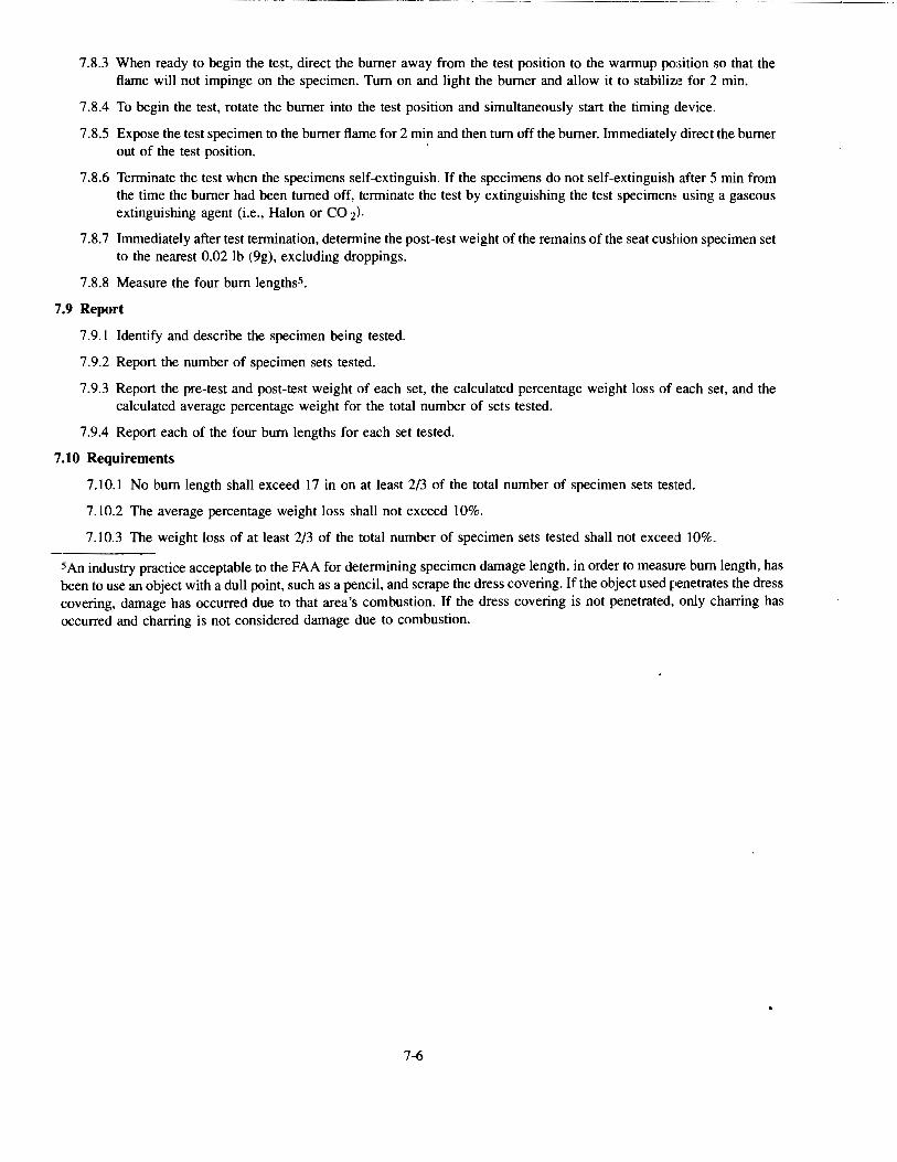
- -~------------·· ---· ·-- ... ----
7 .8.3 When ready to begin the test, direct the burner away from the test position to the warmup position so that the flame will not impinge on the specimen. Turn on and light the burner and allow it to stabiliz,~ for 2 min.
7 .8.4 To begin the test, rotate the burner into the test position and simultaneously start the timing device.
7 .8.5 Expose the test specimen to the burner flame for 2 min and then turn off the burner. Immediately direct the burner out of the test position. ·
7.8.6 Terminate the test when the specimens self-extinguish. If the specimens do not self-extinguish after 5 min from the time the burner had been turned off, terminate the test by extinguishing the test specimens using a gaseous extinguishing agent (i.e., Halon or CO z).
7 .8. 7 Immediately after test termination, determine the post-test weight of the remains of the seat cushion specimen set to the nearest 0.02 lb (9g), excluding droppings.
7.8.8 Measure the four burn lengths5.
7.9 Report
7.9.1 Identify and describe the specimen being tested.
7.9.2 Report the number of specimen sets tested.
7.9.3 Report the pre-test and post-test weight of each set, the calculated percentage weight loss of each set, and the calculated average percentage weight for the total number of sets tested.
7.9.4 Report each of the four burn lengths for each set tested.
7.10 Requirements
7.10.1 No burn length shall exceed 17 in on at least 2/3 of the total number of specimen sets tested.
7.10.2 The average percentage weight loss shall not exceed 10%.
7.10.3 The weight loss of at least 2/3 of the total number of specimen sets tested shall not exceed 10%.
SAn industry practice acceptable to the FAA for determining specimen damage length, in order to measure burn length, has been to use an object with a dull point, such as a pencil, and scrape the dress covering. If the object used penetrates the dress covering, damage has occurred due to that area's combustion. If the dress covering is not penetrated, only charring has occurred and charring is not considered damage due to combustion.
7-6
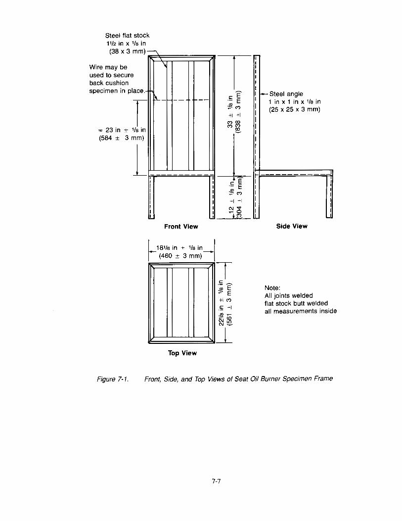
Steel flat stock 11/2 ir:1 x 1/a in (38 x 3 mm) I~
Wire may be used to secure back cushion specimen in place .-
r ,., 23 in ± 1/a in (584 ± 3 mm)
l
\
f\..-1--- f---
I I I I I I I I I I
Front View
I I I I I I I I I
I 181/a in ± 1/a in_. r (460 ± 3 mm)
Top View
TT c:::E ·- E -!2M tl tl C')CO C')C')
~
c:::• E ·- E ~M tl tl C\l'<t ..-0
*"'
T c::: ~E' ~ E tl M
.S tl
r-I I I I I I .L.
I-- Steel angle 1 in x 1 in x 1/a in (25 x 25 x 3 mm)
I
I I I I I I I
....!
Side View
Note: All joints welded flat stock butt welded all measurements inside
Figure 7-1. Front, Side, and Top Views of Seat Oil Burner Specimen Frame
7-7
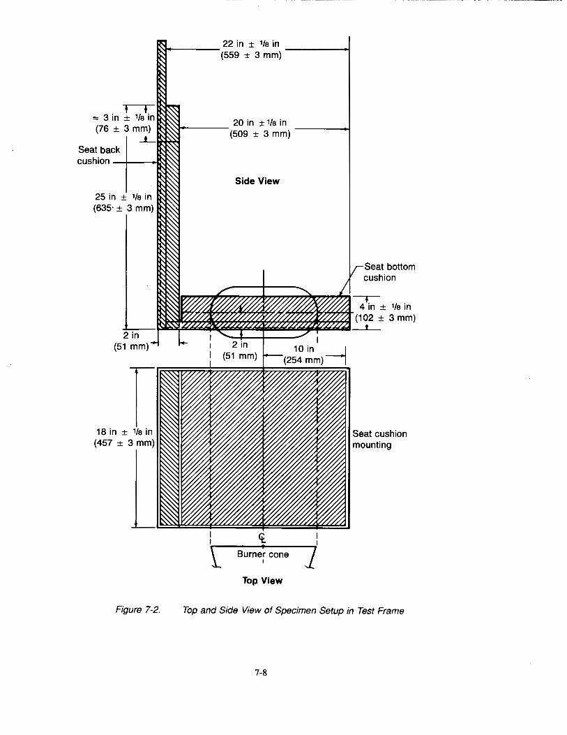
t + "" 3 in ± 1/a in (76 ± 3 mm)
_i_
Seat back
Figure 7-2.
.J----- 22 in ± 1/a in --------+1 (559 ± 3 mm)
~---- 20 in ± 1/a in (509 ± 3 mm)
Side View
<t I
Burner cone I
Top View
Seat bottom cushion
Top and Side View of Specimen Setup in Test Frame
7-8
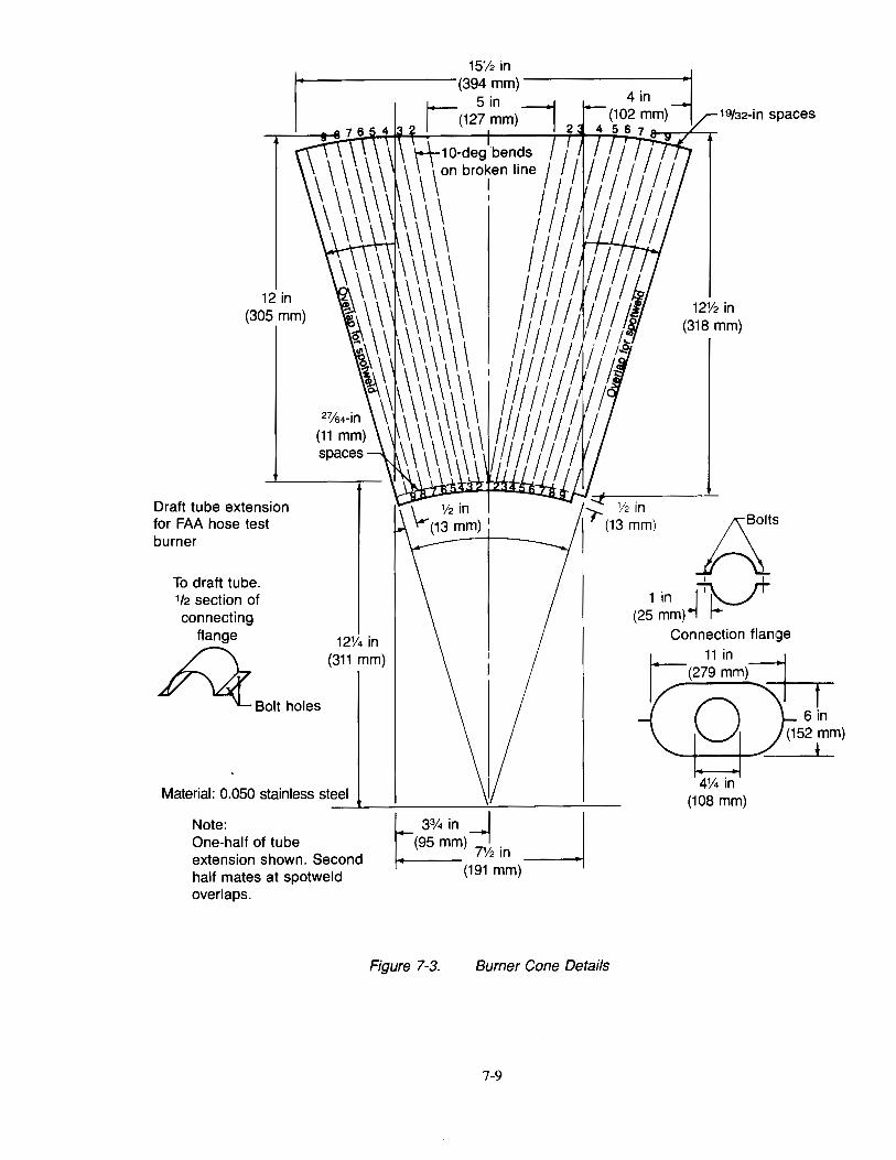
12 in (305 mm)
Draft tube extension for FAA hose test burner
To draft tube. 112 section of connecting
flange 12114 in
~ (311mm)
Bolt holes
Material: 0.050 stainless steel
Note: One-half of tube extension shown. Second half mates at spotweld overlaps.
3%in --J _J (95 mm)
7112 in
(191 mm)
Figure 7-3. Burner Cone Details
7-9
19/32-in spaces
12% in (318 mm)
A' I I
1' '~ (25 ~m)~ P
Connection flan,ge
J;:(27~~m) h 0 ~5~~m) 4% in
(108 mm)
*
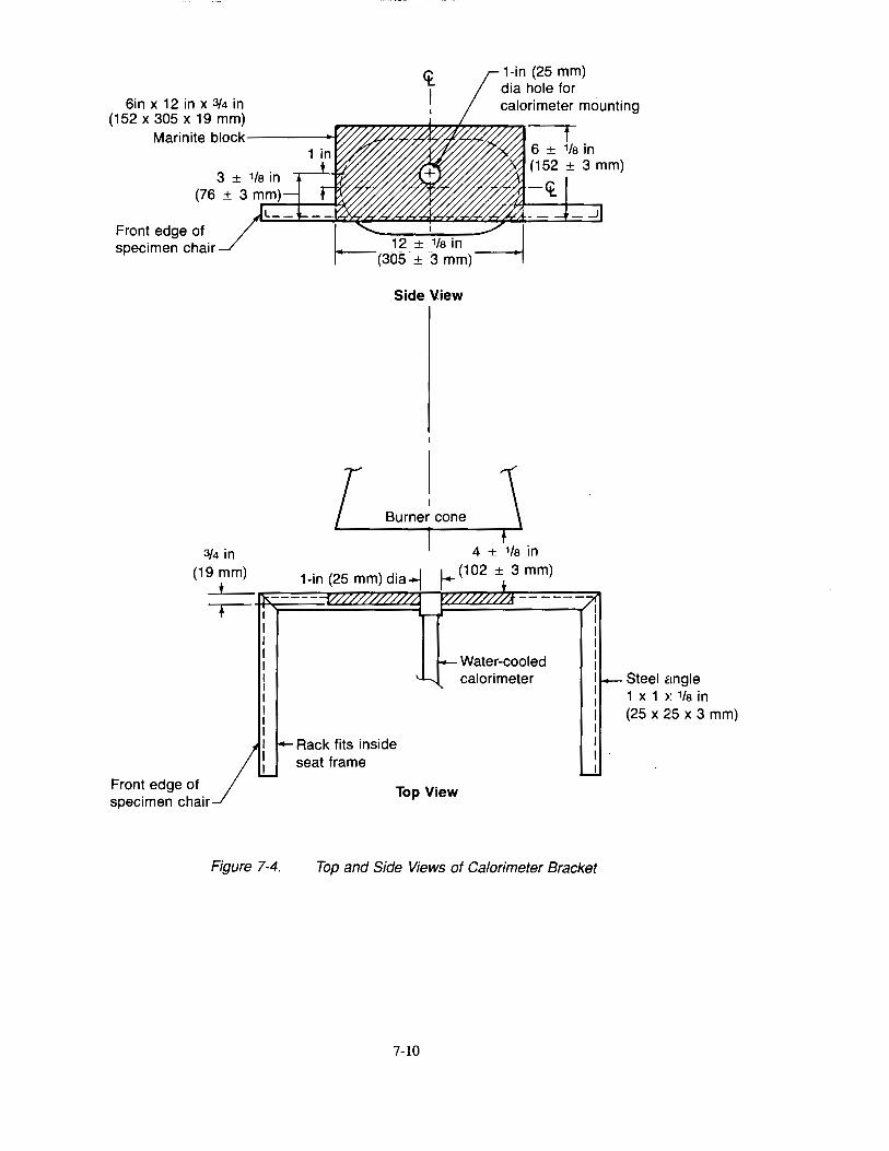
6in x 12 in x 3/4 in (152 x 305 x 19 mm)
<t I
1-in (25 mm) dia hole for calorimeter mounting
Marinite block----..., f
Front edge of specimen chair
3/4 in (19 mm)
t
Front edge of specimen chair
Figure 7-4.
6 ± 1/a in (152 ± 3 mm)
-<t
.Side View
Rack fits inside seat frame
4 ± 1/a in
1- (102 ± 3 mm)
calorimeter
Top View
Top and Side Views of Calorimeter Bracket
7-10
Steel angle 1 x 1 x 1/a in (25 x 25 x 3 mm)
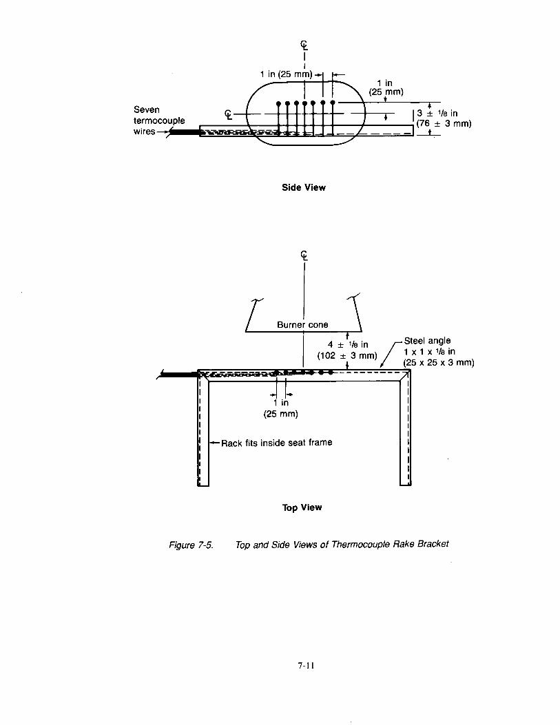
Seven termocouple wires
<t I
Side View
r Burne~ oone j 4 ± 118 in ~Steel angle
(1 02 ± 3 mm) 1 x 1 x 1/a in ~ (25 x 25 x 3 mm)
·-- -.----- •.?(
1 i~ (25 mm)
I-Aack fits inside seat frame
-Top View
Figure 7-5. Top and Side Views of Thermocouple Rake Bracket
7-11
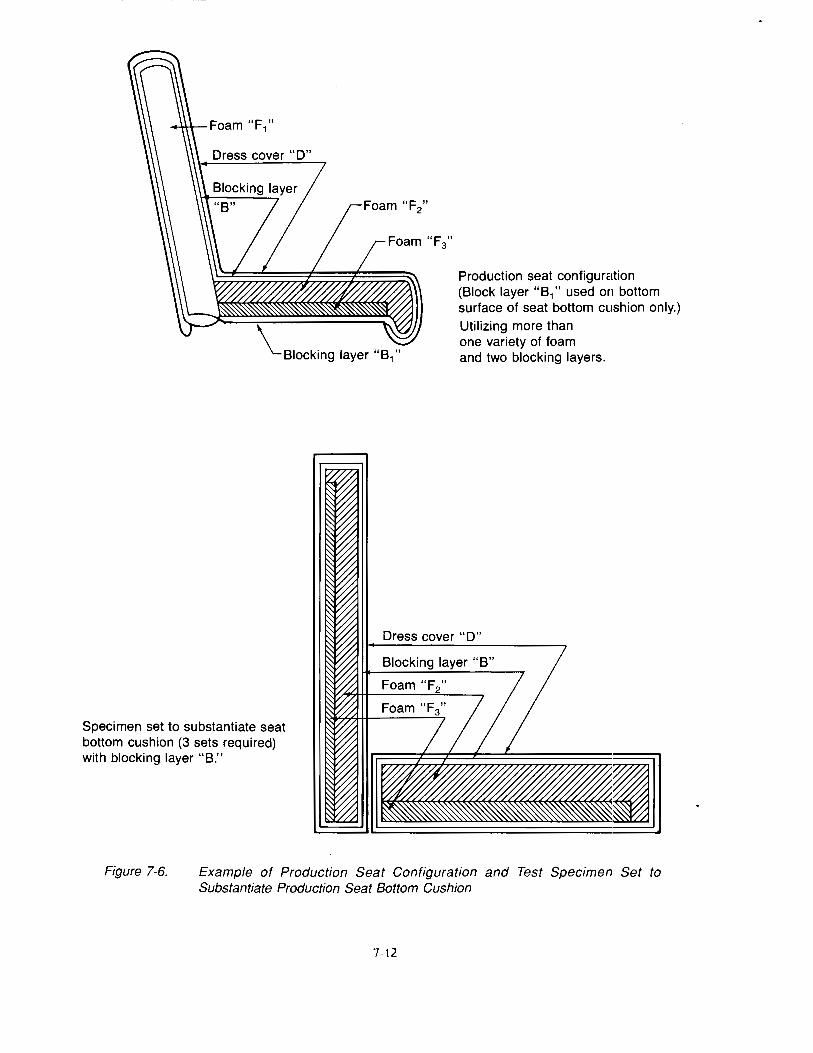
Specimen set to substantiate seat bottom cushion (3 sets required) with blocking layer "B."
Foam "F3"
Production seat configuration (Block layer "B1 " used on bottom surface of seat bottom cushion only.) Utilizing more than one variety of foam and two blocking layers.
Dress cover "D"
Figure 7-6. Example of Production Seat Configuration and Test Specimen Set to Substantiate Production Seat Bottom Cushion
7-12
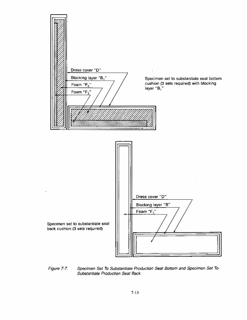
Specimen set to substantiate seat back cushion (3 sets required)
...---
._______
Specimen set to substantiate seat bottom cushion (3 sets required) with blockin<g layer "81"
Dress cover "D"
Blocking layer "B"
Foam"F,"
7 /;
7 ] Figure 7-7. Specimen Set To Substantiate Production Seat Bottom and Specimen Set To
Substantiate Production Seat Back
7-13
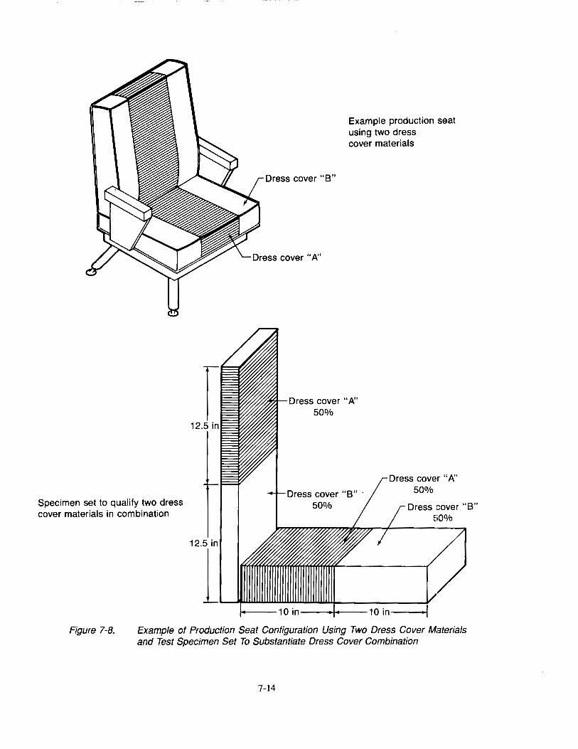
Specimen set to qualify two dress cover materials in combination
Example production seat using two dress cover materials
Dress cover "B"
Dress cover "A" 50%
Dress cover "B" · 50%
Dress cove·r "A" 50%
Dress cover "B" W%
in-----~~---10in----~
Figure 7-8. Example of Production Seat Configuration Using Two Dress Cover Materials and Test Specimen Set To Substantiate Dress Cover Combination
7-14
Chapter 8 Oil Burner Test for Cargo Liners
8.1 Scope
8.1.1 This test method evaluates the flame penetration resistance capabilities of aircraft cargo compartment lining materials utilizing a high intensity open flame.
8.1.2 This test method is used to show compliance to the requirements of FAR Part 25 Section 25.855 through Amendment 25-60. FAR Part 121 Section 121.314 through Amendment 121-202, and FAR Part 135 Section 135.169 through Amendment 135-31.
8.2 Definitions
8.2.1 Bum Through
Flame penetration of the test specimen.
8.2.2 Specimen Set
Three or more replicates of a ceiling and sidewall cargo liner panel installation.
8.3 Apparatus
8.3.1 Test Specimen Frame
The test specimen frame is shown in Figures 8-1 through 8-3. The burner shall be mounted on a swiveling device capable of allowing it to be directed away from the test specimen during warm-up.
8.3.2 Test Burner
The burner shall be a modified gun type such as Park Model DPL 3400, Lennox Model OB-32, or Carlin Model 200 CRD. Flame characteristics may be enhanced by the optional use of tabs 1• Major deviations, such as a different burner type, require thorough comparison testing with a burner that meets FAA specifications. Temperature and heat flux density measurements, as well as test results, would have to correspond to those produced by an FAA approved burner that meets the specifications of FAR PART 25 Appendix F, Part III.
8·.3.2.1 Nozzle
A nozzle shall be provided to maintain the fuel pressure to yield a nominal 2.0 gal/lu (0.126 liter/min) fuel flow. For example, a Monarch 80-deg PLP nozzle nominally rated at 2.25 gal/hr (0.142 L/min) at 100 lb/in 2 (0.69 MPa) operated at 85 lb/in 2 (0.59 MPa) gauge, has been found satisfactory to maintain a fuel flow of 2.0 gal/hr (0.126 L/min) and produce a proper spray pattern. Minor deviations to the fuel nozzle spray angle, fuel pressure, or other parameters of the nozzle are acceptable if the fuel flow rate, flame temperature, and burner heat flux density conform to the requirements of Section 8.6.
8.3.2.2 Burner Cone
A 12 ± l/8 in (305 ±3 mm) burner cone shall be installed at the end of the draft tube. The cone shall have an opening 6 ±1/4 in (152 ±6 mm) high and 11 ±1/4 in (280 ±6 mm) wide. See Figure 8-4.
8.3.2.3 Fuel Pressure Regulator
A fuel pressure regulator that is adjusted to deliver a nominal 2.0 gal/hr (0.126 L/min) flow shall be provided. An operating fuel pressure of 83 ±4 psig (0.57 +/0.03 MPa) for a 2.25 gal/hr (0.142 liter/min) 80-deg spray angle nozzle has been found satisfactory.
1The basic burner and use of tabs is described in FAA Powerplant Engineering Report No. 3A, "Standard Fire Test Apparatus and Procedure for Flexible Hose Assemblies," dated March 1978 and Report No. DOT/FAA/RD/76/213, "Reevaluation of Burner Characteristics for Fire Resistant Tests," dated January 1977. The test settings specified in this specification, however, differ from those specified in the above reports.
8-1
8.3.2.4 Fuel
Either number 2 Grade kerosene or ASTM D2 fuel (number 2 Grade fuel oil or number 2 Grade diesel fuel) may be used if the fuel flow rate, flame temperature, and heat flux density conform to the requirements of the test.
8.3.3 Calorimeter
The calorimeter provided shall be a total heat flux density, foil type Gardon Gauge of an appropriate range, such as 0-15.0 Btu/ft2-sec (0-17.0 W/cm SU2), accurate to ±3% of the indicated reading.
8.3.3.1 Calorimeter mounting
The calorimeter shall be mounted in a 6 by 12 ±1/8-in (152 by 305 ±3 mm) by 3/4-·in (19-mm) thick insulating block which is attached to a steel angle bracket for placement in the test stand during burner calibration. See Figure 8-5. The insulating block shall be monitored for deterioration and the mounting shimmed as necessary to ensure that the calorimeter face is parallel to the exit plane of the test burner cone.
8.3.4 Thermocouples
The seven thermocouples to be used for calibration shall be l/16-in (1.0-mm) ceramic packed, metal sheathed, type K Chromel-Alumel, grounded junction thermocouples with a nominal30 American wire gauge (AWG) size conductor. The seven thermocouples shall be attached to a steel angle bracket to form a thermocouple rake for placement in the test stand during burner calibration as shown in Figure 8-6.
8.3.5 Instrumentation
A recording potentiometer or other suitable calibrated instrument with an appropriate range shall be provided to measure and record the outputs of the calorimeter and the thermocouples.
8.3.5.1 Timing Device
A stopwatch or other device, accurate to 2% of the indicated reading, shall be provided to measure the time of application of the burner flame, the material flaming time, and the bum through time.
8.4 Test Specimen(s)
8.4.1 Specimen Configuration
Each cargo liner panel type and design configuration shall be tested. Design configuration includes cargo compartment design features such as comers, joints, seams, lamp assemblies, pressure relief valves, temperature sensors, etc., that may affect the capability of a cargo compartment to safely contain a fire.
Ceiling and sidewall liner panels may be tested individually provided a baffle of fire-resistant material, such as Kaowool or Marinite, is used to simulate the missing panel.
8.4.2 Specimen Number
A minimum of three specimens or specimen sets for each panel type or design configuration shall be prepared for testing.
8.4.3 Specimen Size
The specimens to be tested shall measure 16 ±1/8 in (406 ±3 mm) by 24 ±1/8 in (610 ±3 mm).
8.5 Specimen Conditioning
8.5.1 The specimens shall be conditioned at 70° ±5°F (21 o ±2°C) and 55% ±5% relative humidity for a minimum of 24 hr prior to testing.
8-2

8.6 Calibration
8.6.1 Remove the burner extension from the end of the draft tube2. Tum on the blower portion of the burner without turning on the fuel or igniters. Measure the air velocity using a hot wire anemometer (a turbine-type velometer has also been found suitable). Adjust the airflow using the damper such that the airflow is in the range of 1,550-1,800 ft/min (762-914 em/sec).
8.6.2 If a calibrated flow meter is not available, measure the fuel flow using a graduated cylinder of appropriate size. Tum on the fuel pump and the burner motor, making sure the igniter system is off. Collect the fuel via a plastic or rubber tube into the graduated cylinder for a 2-min period. Ensure the flow rate is 2.0 ±0.2 gal/hr (0.126 +/0.0 13 L/min).
8.6.3 Secure the calorimeter in its bracket and place it on the specimen mounting test frame, making sure it is centered over the burner cone at a distance of 8 ±l/8 in (203 +/3 mm) from the exit of the burner cone as shown in Figure 8-5. Ensure that the burner is in the proper position in relation with the specimen mounting frame, 2 :tl/8 in (51 +/3 mm) from the sidewall panel frame. Position the center of the calorimeter over the center of the burner cone.
8.6.4 Prior to starting the burner, ensure that the calorimeter face is free of soot deposits and there is water running through the calorimeter.
CAUTION! Exposing the calorimeter to the burner flame without water running through it will destroy the calorimeter.
8.6.5 Move the burner from the vertical position to the warmup position. Examine and clean the burner cone of any evidence of buildup of productions of combustion, soot, etc. Soot buildup inside the burner cone may affect the flame characteristics and cause calibration difficulty.
8.6.6 While the burner is in warmup position, tum on the fuel flow and light the burner. Allow it to warm up for at least 2 min. Move the burner into test position and adjust the air intake to produce a heat flux density of 8.0 ±0.5 Btu/ ft2-sec (9.2 +/0.6 W/cm2)3. Record the heat flux density measurements at least once per second over at least a 2-min time period to ensure steady state conditions have been achieved. After steady state conditions have been achieved, tum the burner off.
8.6. 7 Replace the calorimeter bracket with the thermocouple rake. Check the distance of each of the seven thermocouples to ensure they are located 8 ±l/8 in (203 ±3 mm) from the horizontal plane of the burner exit Place the center thermocouple (thermocouple No. 4) over the center of the burner cone exit. See Figure 8-6.
8.6.8 Tum on the burner and allow it to warm up for at least 2 min. After warmup, record the temperature of the thermocouples at least once per second for a 2-min period. The temperature of each thermocouple shali be I, 700° ±100°F (927° ±56°C). If the temperature of each thermocouple is not within the specified range, repeat sections 8.6.3 through 8.6.8 until all parameters are within the specified ranges. When the required thermocouple temperatures have been achieved, tum off the burner.
8.6.9 Calibrate prior to each test until consistency has been demonstrated. After consistency has been confirmed, several tests may be completed with calibration conducted before and after the tests.
8.7 Procedure
8. 7.1 Examine and clean the cone of soot deposits and debris.
8.7.2 Mount the sidewall and/or ceiling cargo liner specimen(s) on the respective frame(s) and secure to the test frame(s) using the retaining frame(s). Bolt the retaining frame(s) and the test frame(s) together. Verify that the horizontal test frame is level.
2If tabs are being used, the tabs shall be removed prior to measuring the airflow. After the measurement is complete, reinstall the tabs and the cone extension.
3The airflow should be adjusted to produce the proper flame, as well as the proper temperature and heat flux density. Two different flame profiles may yield the same temperature and heat flux density. The correct flame is generally 8 to 10 in in length and orange-yellow in color.
8-3
8.7.3 Mount the thermocouple or thermocouple rake 4 ±1/8 in (102 ±3 mm) above the horizontal ceiling panel test specimen. If the thermocouple rake is being used, position the center thermocouple (thermocouple No. 4) over the center of the burner cone exit.
8.7.4 Move the burner into warmup position so that the flame does not impinge on the test specimen during the warmup period. Tum on the burner and allow it to stabilize for at least 2 min.
8.7.5 Simultaneously move the burner into test position and start the timing device.
8.7.6 Record the temperature of the thermocouple (thermocouple No.4, if using the thermocouple rake also used for calibration) at least once a second for the duration of the test.
8.7.7 Expose the specimen to the flame for 5 min or until flame penetration occurs.
8.7.8 Tum off the burner to terminate the test.
8.8 Report
8.8.1 Report a complete description of the material(s) being tested including manufacturer, thickness, etc.
8.8.2 Report the orientation of the panels tested (i.e., ceiling and/or sidewall).
8.8.3 Record any observations regarding the behavior of the test specimen during flame exposure such as delamina-tion, resin ignition, smoke, etc. and time of occurrence of each event.
8.8.4 Report the time of occurrence of flame penetration, if applicable, for each of the three specimens tested.
8.8.5 If flame penetration does not occur, report the maximum backside temperature and time of occurrence.
8.8.6 Provide a record of calibration.
8.9 Requirements
8.9.1 None of the three specimens tested shall bum through within the 5-min flame exposure.4
8.9.2 Each of the three specimens tested shall not exceed 400°F at the backside temperature monitored during flame exposure.
8.9.3 Specimens that pass in the ceiling orientation may be used as a sidewall panel without further test.
4FJames that may appear on the side of the specimen away from the burner or as a result of the ignition of flammable smoke and/or gases produced from the specimen by the heat from the burner do not constitute bum through. Bum through occurs only if the flame from the burner passes through the specimen.
8-4

48 in (1 ,219 mm)
Top View
I 24in
(610 mm) I
Horizontal and vertical specimens are clamped in place on all edges betwE~en angles as shown in view A - A
Test stand frame
Vertical spec
\_Horizontal spec
Support an,gle
View A- A (Typical)
I-- 16 in ---1 1 (406 mm) 1
~R=--~-:::::-:::::-:::::-::::::--=1=::-:::-:::::-::::::--:::::-=-~ ---.-I 4 in (102 mm)
~~~~~!1 I 16 in : (406 mm)
r- 2 in (51 mm)
-L--+f-
I
---4~......-1-----....a.-;:1------- Burner shield-------'~+-"'-+----
Front View
1 x 3 x 1/a in (25 x 76 x 22 mm) Steel "U" channel
Side View
Figure 8-1. Test Apparatus for Horizonal and Vertical Mounting for Cargo Liner Oil Burner Testing
8-5
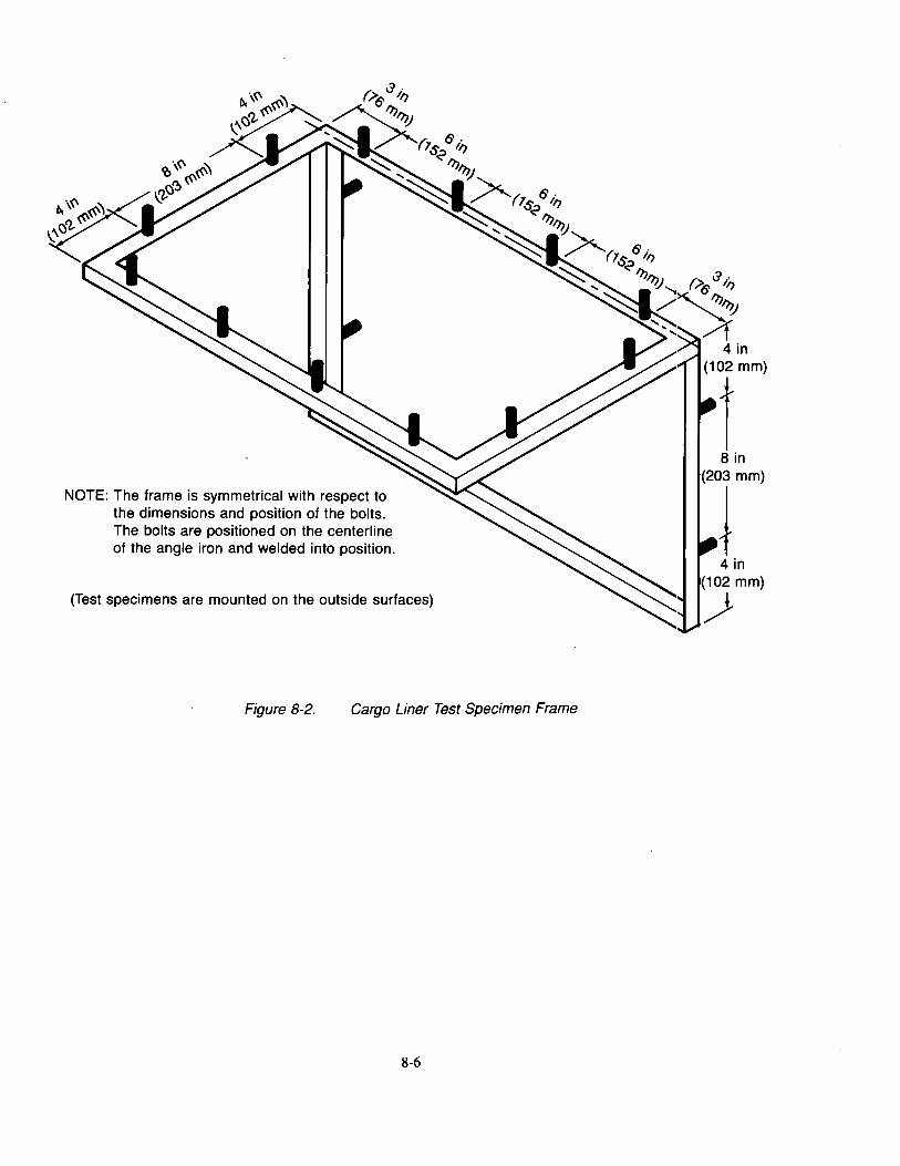
NOTE: The frame is symmetrical with respect to the dimensions and position of the bolts. The bolts are positioned on the centerline of the angle iron and welded into position.
(Test specimens are mounted on the outside surfaces)
Figure 8-2. Cargo Liner Test Specimen Frame
8-6
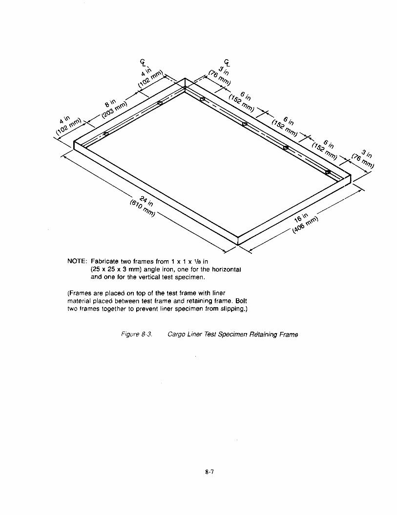
NOTE: Fabricate two frames from 1 x 1 x 1/a in (25 x 25 x 3 mm) angle iron, one for the horizontal and one for the vertical test specimen.
(Frames are placed on top of the test frame with liner material placed between test frame and retaining frame. Bolt two frames together to prevent liner specimen from slipping.)
Figure 8-3. Cargo Liner Test Specimen Retaining Frame
8-7
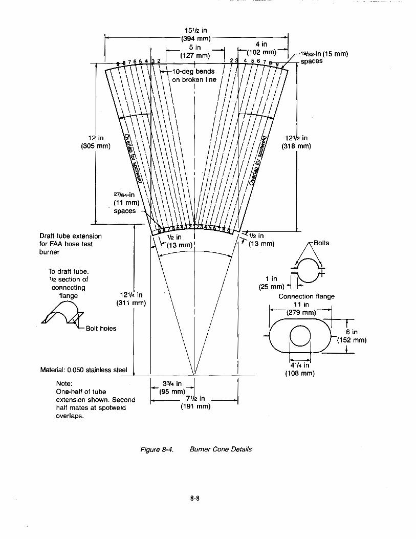
19/32··in (15 mm) -r-~r::!2-~*+~-+--~-T--T-~~.,.-r-, spac:es
12in (305 mm)
Draft tube extension for FAA hose test burner
To draft tube. 112 section of connecting
flange 12114 in £')_, (311 mm)
,£/ ~Bolt holes
Material: 0.050 stainless steel ___.. ____ _,____ ___ _ Note: One-half of tube extension shown. Second half mates at spotweld overlaps.
~~!:'~~ I _j ~>;:)2in
(191 mm)
Figure 8-4. Burner Cone Details
8-8
121 2 in (318 mm)
p;:_· I I
1 in ~.;r (25 mm) +l t-
Connection flange
1;:(2~ ~m) =+-r o](15~i~m) 41/4 in
(108 mm)
~
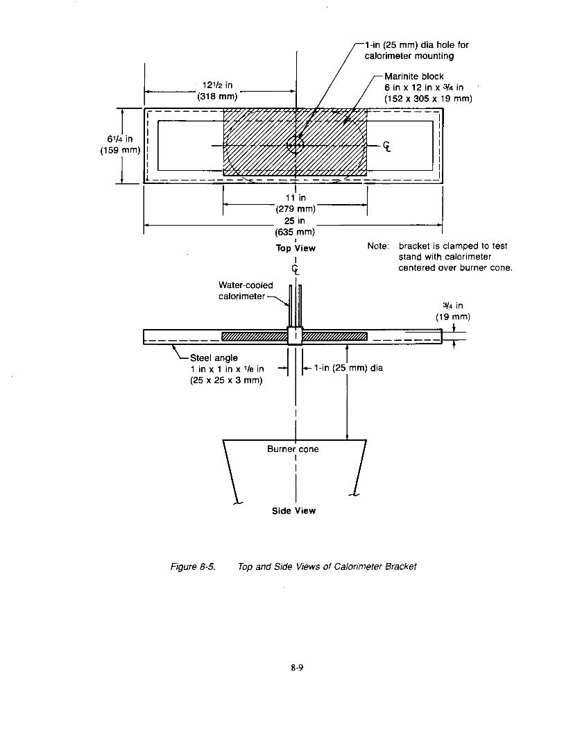
I 12112 in r-----(318 mm) I:-------
/ . I
614 In 1
(159 mm) :
L l----------'----
1-in (25 mm) dia hole for calorimeter mounting
Marinite block 6 in x 12 in x 3/4 in (152 x 305 x 19 mm)
1
I 11 in I I t·-(279 mm)-•i
... 25 in ----i• (635 mm)
Water-cooled calorimeter
I
Top View I
ct.
Note: bracket is clamped to test stand with calorimeter centered over burner cone.
3/4 in (19 mm)
Steel angle I I 1 in x 1 in x 1/a in -j f-1-in (25 mm) dia (25 x 25 x 3 mm)
Figure 8-5.
Burner cone I I
Side View
Top and Side Views of Calorimeter Bracket
8-9
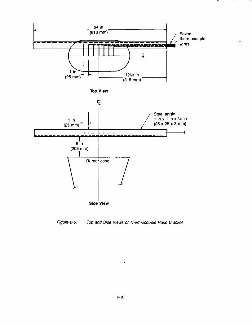
r ;7
24in (610 mm)
1 in (25 mm)· I- I
•
Top View
1 in I I (25 mm>l r
Side View
~
..-
I -
12112 in (318 mm)
<t
£ /
Steel angle
Seven thermocouple wires
1 in x 1 in x 1/e in (25 x 25 x 3 mm)
Figure 8-6. Top and Side Views of Thermocouple Rake Bracket
8-10
Chapter 9 Radiant Heat Testing of Evacuation Slides, Ramps, and Rafts
9.1 Scope
9.1.1 This test method is used to show compliance to TSO C69A.
9.2 Definition
9.2.1 Time to Failure
The time to failure is the time between first application of heat to the specimen and the first decrease in pressure below the maximum pressure attained in the test cylinder during the test.
9.3 Test Apparatus
9.3.1 Pressure Cylinder and Specimen Holder
The pressure cylinder shall consist of a 12% in (314 mm) long aluminum cylinder with a 7 in ( 178 mm) outside diameter and a 6Yz in (165 mm) inside diameter as shown in Figures 9-1, 9-2, and 9-3.
An aluminum plate Yz in ( 13 mm) thick shall be welded to one end of the cylinder, and shall be drilled and tapped near its upper edge for a lf4 in (6.4 mm) American Standard taper pipe thread to facilitate the hook up of air pressure and pressure recording equipment.
An aluminum ring 7 in (178 mm) in outer diameter, 5Yz in (140 mm) in inner diameter, and Vz in (13 mm) thick shall be welded to the other end of the cylinder. The ring shall have eight evenly spaced 10-32 bolt holes on the circle 5/16 in (8 mm) from the ring's inner edge (the diameter of this circle is 6 \Is in (156 mm) and adjacent bolt holes are 25/16 in (60 mm) apart). A 10-32 steel bolt 7/s in (22 mm) long shall be placed into each of the holes.
An aluminum ring 6% in (171 mm) in outer diameter, 5Vz in (140 mm) in inner diameter, and Vz in (13 mm) thick, and two neoprene rubber gaskets with similar clearance holes to fit over the bolts shall provide a means for clamping and sealing the test specimen in place. Hinges and adjustable stops shall be welded to the sildes of the cylinder! as shown in Figures 9-1, 9-2, and 9-3.
9.3.2 Electric Furnace
An electric furnace with a 3-in (76-mm) diameter opening, as shown in Figure 9-4, shall be provided to supply a constant irradiance on the specimen surface. The Smoke Density Chamber radiant heat furnace,2 or equivalent, has been found suitable.
9.3.3 Furnace Voltage Control
A variable voltage control 115V, 600W minimum shall be provided to connect to the electric furnace power supply in order to adequately control the heat flux from the furnace. The furnace control system shall be capable of maintaining the irradiance level under steady-state conditions for a minimum of 20 min.
9.3.4 Calorimeter
A 0-5 Btu/ft2-sec calorimeter3 shall be provided to monitor the heat flux from the furnace. The calorimeter shall be mounted in a 41/z in ( 114-mm) dia by %-in ( 19-mm) thick insulating block, such as calcium-silicate mill board,
I Figure I represents an alternate method of securing the specimen in place on the holder by the use of toggle clamps instead of welded hinges and adjustable stops.
2Available from Superpressure, Inc. 8030 Georgia Ave. Silver Springs, MD 20910 (Cat No. #D-257-68086)
3 Available from Hy-cal Engineering 12105 Los Nietos Road Santa Fe Springs, CA 90670 (Model C-1300-A)
9-1
with the surface of the calorimeter flush with the surface of the insulating block. The calorimeter shall be hinged to one of the sliding bars of the framework and centered with the furnace. See Figure 9-3.
9.3.5 Apparatus Framework
The pressure cylinder, calorimeter, and furnace are mounted on a framework as detailed in Figure 9-3. Adjustable sliding stops are located on each of the bars for setting the cylinder and calorimeter at any distance from the opening of the furnace.
9.3.6 Pressure Supply and Equipment
Compressed air is connected to the cylinder through a needle valve attached to the end of the framework. A teemanifold on the outlet side of the valve provides for a 0 to 5 psig pressure gauge, transducer, flexible tube to supply air to the rear plate of the pressure cylinder, and a bleed valve as shown in Figure 9-1.
9.3 .7 Instrumentation
The outputs of the calorimeter and pressure transducer are measured and recorded using a recording potentiometer or other suitable instrument capable of measurement over the range required.
9.4 Test Specimens
9.4.1 For each test, at least three specimens 7 in (178 mm) in diameter with eight 1/4 in (6-mm) holes punched in the material to match the studs in the pressure cylinder shall be cut from the material to be tested.
9.4.2 If the pressure holding material has any exposed surfaces which are marked, have overlay material, have seams, or are altered in any other manner which affects radiant heat resistance, each different surface shall be tested as a specimen set.
9.5 Conditioning
9.5.1 Condition test specimens at 70° ±5°F (21 o ±3°C) and 50% ±5% relative humidity for a minimum of 24 hr prior to testing.
9.6 Calibration
9.6.1 Tum on the radiant heat furnace and other required instrumentation and allow 1h to% hr to stabilize heat output and for instrumentation warmup.4
9.6.2 Adjust the transformer to produce a radiant heat flux density of 2 Btu/ft2-sec (2.3 W/cm2), when the calorimeter is positioned at approximately 1lf2 in (38 mm) in front of the radiant heat furnace.
9.6.3 Find the precise location in front of the furnace where the test heat flux density of 1.5 Btu/ft2-sec (1.7 W/cm2) is achieved by sliding the calorimeter on the horizontal bar and fixing the position with the sliding stop. Swing the calorimeter out of position.
9.7 Procedure
9.7.1 Conduct the tests in a draft free room or enclosed space. It is recommended tests be conducted under a hood or other means to remove potentially hazardous gases from the test area.
9.7.2 Tum on the radiant heat furnace and other required instrumentation and allow 1h to% hr to stabilize heat output and for instrumentation warmup.4
9.7.3 Rotate the cylinder away from the furnace. Mount the specimen with the reflective surface of the material facing the furnace on the open end of the cylinder with a neoprene gasket on each side of the specimen. Place the aluminum ring on the studs and tighten the nuts so that an airtight seal is achieved.
9.7.4 Pressurize the cylinder to the slide material nominal operating pressure and check for leakage.
4To prolong the life of the furnace, increase the voltage to cold furnace slowly.
9-2
9.7.5 Locate the pressure cylinder so that the distance from the test specimen to the surface of the radiant heat furnace is the distance established in Section 9.6.3.
9.7.6 Place the calorimeter in front of the radiant heat furnace at the distance established in Section 9.6.3 and record the heat flux density. Verify the heat flux is of 1.5 Btu/ft-sec (1.7 W/cm2). Remove the calorimeter.
9.7.7 Rotate the pressure cylinder with test specimen in front of the radiant heat furnace. Start the timer.
9.7.8 Monitor the pressure from the time the specimen is placed in front of the furnace until the first observed pressure loss.
9.7.9 Record time to failure in seconds.
9.8 Report
9.8.1 Report material description and full identification that may include type of fabric and coating, manufacturer, manufacturer style number, weight, thickness, color, and any alterations, if applicable.
9.8.2 Report the test conditions, including the heat flux density and starting pressure for each of the three specimens.
9.8.3 Report any observations of the material behavior during the test and times of occurrence.
9.8.4 Report the time to failure for each of the three specimens and overall average.
9.9 Requirement
9.9.1 The average time to failure for the three specimens tested shall not be less than 90 sec.
9-3
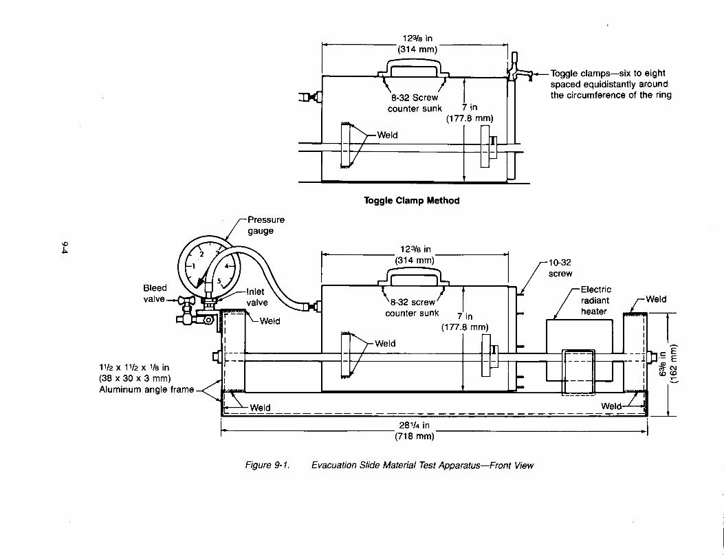
\0 .1:..
~ '+I I';> , fJf=y-- Toggle clamps-six to eight spaced equidistantly around the circumference of the ring
Bleed valve~
1112 x 1112 x 1/a in (38 x 30 x 3 mm) Aluminum angle frame
counter sunk 7 in (177.8 mm)
Weld
Toggle Clamp Method
123la in _____ ....., (314 mm)
counter sunk
Weld
281/4 in 1-------------(718 mm)
Figure 9-1. Evacuation Slide Material Test Apparatus-Front View
Electric radiant heater
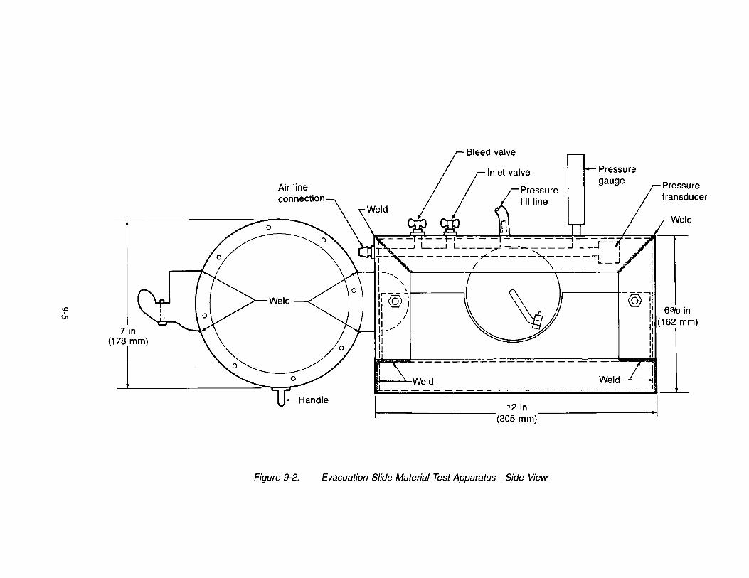
\0 I
Vl
7in (1r
Air line connection
Pressure fill line
Pressure gauge
II• ' Weld Weld ' •UI l---- __ --------- _ -----------1
I_ ~-
12in (305 mm)
Figure 9-2. Evacuation Slide Material Test Apparatus-Side View
Weld
63/a in (162 mm)
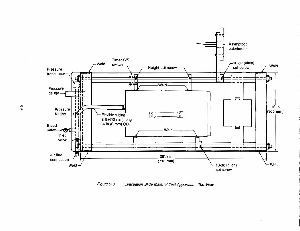
\C) I
0'1
Press transd
Pres gaug
p
f
Bleed valve
Air con
-Timer S/S
Jre /Weld switch\ 1 Height adj screw--="
ucer\
~~ ±: ....... '"r•
I -
I cz... - Weld L, ,J : v \ ;ure I I
9 [ :::I I 1 I I 1 I I I I
ressure I I /,' I 1:
I line ~((' ~Flexible tubing ~ ~I 0
I I I 2 ft (610 mm) long I I I Y4 in (6 mm) OD I I
-JO..I _...J I I I Weld - •I I I Inlet I I I
valve ..Ia I
14 L __ ~
t--!-i I• I ~
:ne tl/ ?R1/4 in \ WeldJ
Figure 9-3. Evacuation Slide Material Test Apparatus-Top View
r-....-
~=-=• ~~-
- ~-1--Asymptotic
-~- calorimeter
I ; 1:.: ~ -
/
1
10-32 (allen) set screw
-~------L.-
~
t=
10-32 (allen) set screw
~---~
12 (305
---~ \I-
,,
n mm)
d
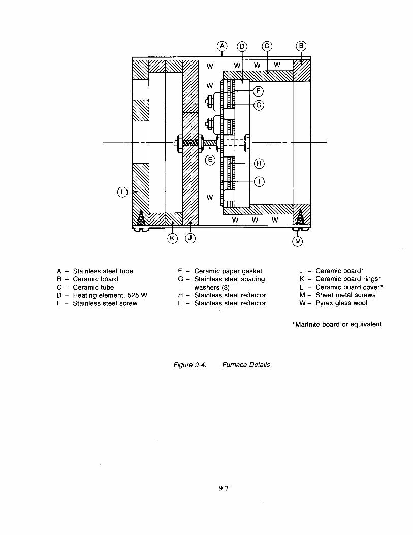
A - Stainless steel tube B - Ceramic board C - Ceramic tube D - Heating element, 525 W E - Stainless steel screw
0® @)
w
®0
F - Ceramic paper gasket G - Stainless steel spacing
washers (3) H - Stainless steel reflector I - Stainless steel reflector
Figure 9-4. Furnace Details
9-7
®
J - Ceramic board* K - Ceramic board rings* L - Ceramic board cover* M - Sheet metal screws W - Pyrex glass wool
* Marinite board or equivalent
This page intentionally left blank
9-8
Chapter 10 Fire Containment Test of Waste Stowage Compartments
10.1 Scope
10.1.1 These methods are intended for use in determining the fire containment capability of containers, carts, and compartments used to store combustible waste materials according to the requirements of FAR 25.853(e) through Amendment 51.
10.1.2 Part constructions used for the top, bottom, and sides of these compartments must also meet the requirements of FAR 25.853(a-l) and FAR 25.855(a-1)(2). These tests are covered elsewhere in this handbook under Vertical Bunsen Burner Test for Cabin, Cargo Liner Materials and Flame Penetration Test for Cargo Compartment and Waste Stowage Compartment Materials, and 60-deg Bunsen Burner Test for Electrical Wire.
10.1.3 There are multiple test arrangements covered in this specification: Entree Carts, Meal Carts, Waste Carts, and Waste Compartment Meal Boxes (see Table 10-1).
10.2 Definitions
10.2.1 Air Ducting
Ducting used for conveying chilled air to and from carts.
10.2.2 Waste Cart
A movable enclosure on wheels providing an enclosed means of accumulating and/or storing waste.
10.2.3 Meal Cart
A movable enclosure on wheels used to store food, and used or unused service trays that might contain waste.
10.2.4 Entree Cart
A movable enclosure on wheels used .to cook or store food at elevated temperatures, and transport/store unused or used food service trays that might contain waste.
10.2.5 Integral Floor
The bottom panel of a waste compartment. 1
10.2.6 Waste Compartment (galley or lavatory module)
An enclosure or shell structure with access provisions, such as a waste chute opening or doors, designed for the purpose of accumulating or storing waste.
10.2.7 Waste Container
A removable receptacle stored within a waste compartment or waste cart designed to accumulate or store waste within the compartment or cart.
10.2.8 Meal Box
A removable enclosure located in a meal trolley or galley compartment used to store food and used or unused service trays that might contain waste.
10.3 Test Apparatus/Equipment
10.3.1 Thermocouple(s)
Thermocouple(s) may be needed to monitor internal test unit temperature. If thermocouples are used:
I An integral floor is part of the galley /waste compartment. It is not the aircraft floor panel.
10-1
10.3.1.1 For meal or entree carts, a thermocouple shall be installed 1.5 to 2.0 in above the top-most tray. A second thermocouple is placed on the bottom tray in a similar manner.
10.3.1.2 For waste compartments/carts, a single thermocouple is inserted through the waste flap and placed 1.5 to 2.0 in above the waste combustibles surface.
10.3.2 Thermocouple Readout/Recording
If used, thermocouples shall be connected to a system that is capable of providing continuous temperature readings. A recording system shall be utilized such that temperatures can be recorded continuously or at intervals not exceeding 15 sec.
10.3.3 Galley
Galley structure to simulate the interface needed for the stowed cart test arrangements.
10.3.3.1 The galley structure shall be equipped with power outlets and air inlet/outlet ducting to circulate ambient air at the design specified airflow to the cart when setup to conduct testing.
10.3.4 Waste Materials
1 0.3.4.1 Combustibles
10.4 Test Unit
10.3.4.1.1 Meal Cart Test Arrangement
1 Set of plastic eating utensils 1 cup 1 salad dish 1 salad dressing container 1 entree dish 1 dessert dish 1 crumpled 2-ply paper napkin, approximately 16 by 16 in
The trays, each loaded with the above combustibles, or equivalent combustibles representative of the materials found in service, shall be inserted into the cart such that 75% of the trays are loaded within the cart from the bottom.
10.3.4.1.2 Entree Cart Test Arrangement
Combustibles shall consist of the same items per tray as required for the meal cart for the stowed test. For the fire source, the bottom tray shall have an entree dish half-filled with methyl alcohol to simulate grease. The napkin shall not be located near the alcohol source. For the unstowed test, treat the entree cart as a meal cart.
1 0.3.4.1.3 Waste Compartment/Waste Cart
Combustibles shall be crumpled and consist of the following proportions of materials or an equivalent:
8 2-ply paper hand towels, approximately 10 by 11 in (40% by number) 5 2-ply paper napkins approximately 16 by 16 in (25% by number) 4 Paper hot drink cups 8 oz (20% by number) 2 Paper cold drink cups 3 oz (10% by number) 1 Empty cigarette package (5% by number)
The total amount of the above crumpled combustibles, in the above proportions, shall be sufficient to fill the waste compartment or waste container to three quarter capacity.
1 0.4.1 The unit to be tested shall be equivalent to an actual production unit, built to drawing specifications and tolerances.
10.4.2 A statement of conformity shall be obtained for each test unit prior to testing.
10-2
10.5 Test Arrangements
10.5.1 The test shall be conducted in an environment simulating conditions in which the test unit is expected to be exposed to in actual use. In all arrangements, the test setup shall simulate the largest degree of misalignment. 2
10.5.1 Meal Cart Test Arrangements
10.5.1.1 Unstowed Meal Cart
The unstowed meal cart test arrangement requires a condition where the cart is tested in a freestanding position. Photographs, as discussed in section 10.7.3, shall show the door with the chilled air duct interfaces (if applicable).
10.5.1.2 Stowed Meal Cart
The stowed meal cart test arrangement requires the cart be installed in the galley cart compartment with the air inlet/outlet openings connected to the air ducting. During the test, air is to be circulated through the cart at the design flow rate. Photographs of the meal cart should be taken from the side to show the cart vendor, required to simulate the cart/galley interface. The maximum cart/galley misalignment shall be reproduced during the test.
10.5.2 Waste Cart Arrangements
Testing both with and without the waste container is required if the waste container is nonmetallic. The waste cart interface with the galley; i.e., galley waste flap and waste chute; is also required to be simulated if the waste chute enters the cart enclosure and/or keeps the cart waste flap open.
10.5.2.1 Unstowed waste cart (waste container not installed)
An Unstowed waste cart (waste container not installed) test arrangement requires a freestanding position at room temperature and still air. Photographs must be taken showing the cart door and flap.
10.5.2.2 Unstowed waste cart (waste container installed)
An unstowed waste cart (waste container installed) test arrangement requires that the cart be in a freestanding position, per section 10.5.2.1 above, with the waste container installed.
10.5.2.3 Stowed waste cart (waste container not installed)
A stowed waste cart (waste container not installed) test arrangement requires the interface of the galley structure with the cart be simulated. The cart shall be stowed in a galley mockup that completely simulates the galley/cart interface. Photographs shall be taken that clearly show the waste chute/waste cart interface, as well as the cart door, during the test.
10.5.2.4 Stowed waste cart (waste container installed)
The stowed waste cart (waste container installed) arrangement is equivalent to section 10.5.2.3, except that a waste container is installed.
10.5.3 Entree Cart Arrangement
10.5.3.1 Unstowed Entree Cart
An unstowed entree cart test arrangement requires that the cart be tested in a freestanding position at room temperature and still air.
10.5.3.2 Stowed Entree Cart
A stowed entree cart test arrangement requires that the cart be connected to the galley power and, if applicable, air ducting outlets. Power shall be supplied to the cart for the duration of the test. All
2Misalignment generally refers to maximum air gaps, maximum seal interferences, minimum overlaps, etc. allowed by drawing tolerances. Misalignment must be simulated during testing because, with repeated waste receptacle handling, seals are unlikely to remain airtight. Misalignment may be represented during the test by using a %-inch shim to support the door open.
10-3
heaters and fans shall be switched on with any timers set to the maximum duration. If the cart receives air from the galley ducting when the power is switched off, then a third test (stowed meal cart test arrangement) is required.
10.5.4 Waste Compartment Arrangements
10.5.4.1 The only condition in which waste compartments without an integral bottom or base panel are to be tested is with the waste container installed within the waste compartment. If a liner is used within the waste container, the test shall be conducted both with and without the liner installed. Ambient condition shall be room temperature and still air. Photographs shall show the waste compartment door and the waste flap.
10.5.4.2 Waste compartments may be tested without a waste container only for waste compartments with an integral floor. If the waste container is nonmetallic, then a waste compartment with an integral floor must be tested both with and without the waste container installed. If a liner is used within the waste container, the test shall be conducted both with and without the liner installed.
10.5.5 Meal Box Arrangements
The different types and arrangements of meal boxes that require testing are defined in Table 10-1. Meal boxes are to be tested in the same manner as a meal cart (see section 1 0.6.1 ).
10.6. Test Procedure
1 0.6.1 Ignition
1 0.6.1.1 Meal Cart
10.6.1.1.1 Stowed meal cart test arrangement
Ignite two crumpled 2-ply paper napkins of approximately 16 by 16 in size and place them side by side adjacent to the combustibles, defined in Section 10.3.4, already in place, on the bottom tray the greatest possible distance from the air inlet/outlet openings of the cart. Allow a good flame front to develop by allowing approximately 50% of the surface of the waste materials to ignite. Insert the tray into the cart, record the temperature, and close the door. Place the cart into the simulated galley structure so that it is connected with the galley duct/cart interface. The airflow through the crut shall be at the design airflow rate.
10.6.1.1.2 Unstowed meal cart test arrangement
Ignite two crumpled 2-ply paper napkins of approximately 16 by 16 in size and place them side by side adjacent to the other combustibles, defined in Section 10.3.4, already on the bottom tray. Allow a good flame front to develop by allowing approximately 50% of the surface of the waste materials to ignite. Insert the tray into the cart, and simultaneously close the door and record the temperature, if temperature is being monitored.
10.6.1.2 Entree Cart
10.6.1.2.1 Stowed Entree Cart
Connect the entree cart filled with the combustibles of section 10.3.4.1.2 to the power source and energize all heaters and/or fans. Ignite the methyl alcohol in the entree dish on the bottom tray by placing a burning napkin onto the tray. Insert into the cart and close the cart doors and simultaneously record the temperature, if tempe:rature is being monitored.
1 0.6.1.2.2 Unstowed Entree Cart
Proceed per the unstowed meal cart test configuration of section 10.6.1.1.2.
10-4
10.6.1.3 Waste Cart
10.6.1.3.1 Stowed Waste Cart, with waste container
Ignite a paper napkin and place within the waste container through the waste flap. Allow a good flame front to develop by allowing 50% of the surface of the waste materials to ignite. Close the waste flap and simultaneously record the starting temperature.
10.6.1.3.2 Stowed Waste Cart, without waste container
Proceed per section 10.6.1.3.1, except that no waste container is used.
1 0.6.1.3.3 Unstowed Waste Cart, with waste container
Proceed per section 10.6.1.3.1.
10.6.1.3.4 Unstowed Waste Cart, without waste container
Proceed per section 10.6.1.3.2
1 0.6.1.4 Waste Compartment, with and without waste container
Proceed per applicable waste cart arrangement, sections 10.6.1.3.1 and 10.6.1.3.2.
1 0.6.1.5 Meal Box
Proceed per section 1 0.6.1.1.
1 0.6.2 Temperature
If temperature is being monitored, it shall rise rapidly, peak, and then fall below 150°F (66°C) as the flame dies out. The peak in temperature is necessary to identify that combustion has taken place. An example of this temperature peak is visualized in the temperature versus time plot of Figure 10-1. When the temperature indicated by the thermocouple falls below 150°F, the test is terminated and the item examined for damage. If a suitable temperature peak above 150°F is not obtained after three trials, sufficient ventilation shall be provided to achieve a peak.
1 0.6.3 Photographs
Photographs, preferably in color, are required to document the progress of the test. Suggested photographs which may be taken include: test unit before test, test setup, at time of ignition (with door or flap closed), at 30 sec into test, at 1 min, 2 min, 3 min, 5 min, 7 min, 10 min, and at 5-min intervals thereafter. Include detailed photographs showing any damage sustained as a result of the fire. Photographs taken during the test shall have a dark background to show smoke in contrast.
10.6.4 Inspection
After the test has been terminated, the test unit shall be inspected for damage. The doors shall be opened and the extent of combustion of the waste materials shall be noted. Photographs of these waste materials and any damage to the cart or compartment, or lack of damage, shall be ta)<en. Care should be taken to completely document any damage, from simple smoke stains and melting of trays to major bum through of any panels.
10.7 Report
10.7 .1 Identification of Specimen
Completely identify the unit being tested and intended use.
10.7 .2 Description
The results of the test shall be described in a concise manner regarding any observable smoke or fire from within the item. Any deterioration, bum-through, or deformation of the panels caused by heat or flame shall be noted and described along with the time of occurrence. Any damage to the item and/or surrounding structures during the test shall be noted. Any damage to the contents shall be described, including the degree of combustion of the articles placed within the unit, damage to trays, seals, etc.
10-5
10.7.3 Temperature Versus Time Plot
A temperature versus time plot may be supplied in the report if temperature is monitored during test. An example of a temperature versus time plot is shown in Figure 10-1.
10.7.4 Test Photographs
The photographs taken per Section 10.6.3 of the test method shall be included with the report. Photocopies of photographs are not acceptable. A short description shall accompany each photograph.
10.7.5 Acceptance of Results
A statement as to weather the acceptance criteria are met shall be made in the report.
10.7.6 Statement of Conformity
The statement of conformity sheet shall be included with the test report.
10.7.7 Summary of Data
A summary may be prepared and included with the test report.
10.8 Requirements
10.8.1 The temperature indicated by the thermocouple(s), if used, after ignition shall rise rapidly, peak, and then fall steadily as the fire burns out. To be valid the test shall have a definitive peak to demonstrate that a fire has taken place. If no peak is visible or a good flame front cannot be achieved, the test shall be repeated up to three times to demonstrate sufficient effort was made to produce such a temperature peak or flame front.
10.8.2 The test unit shall be able to contain a fire within the enclosure.
10.8.2.1 Fire/flame shall not penetrate through or issue from the bottom, top, or sides of the waste compartment/container, and adjacent material shall not be ignited by heat from the test article.
10.8.3 Smoke shall be contained within the waste compartment/container to the extent that the smoke level produced in the cabin does not create a hazardous condition or interfere with fire-fighting procedures.
10-6

Table 10-1. Meal Box Test Arrangements
Meal box Equipment stowed in: Enclosed galley Open trolley Enclosed trolley description Open galley compartment compartment compartment
compartment
Metalic meal No test required No test required Test meal box Test trollety box, complete within trolley enclosure compartment
Metallic meal Uncertifiable for Test meal box Uncertifiable for Test meal box box, incomplete waste storage within the waste storage within trollley enclosure compartment compartment
Nonmetallic Test meal box Test meal box Test meal box Test trolley meal box, (unstowed) (unstowed) within trolley compartment complete compartment with and without enclosure meal box
Nonmetallic Uncertifiable for Test meal Uncertifiable for Test trolley meal box, waste storage box/compartment waste stowage compartment incomplete combination with and without enclosure (stowed) meal box
10-7
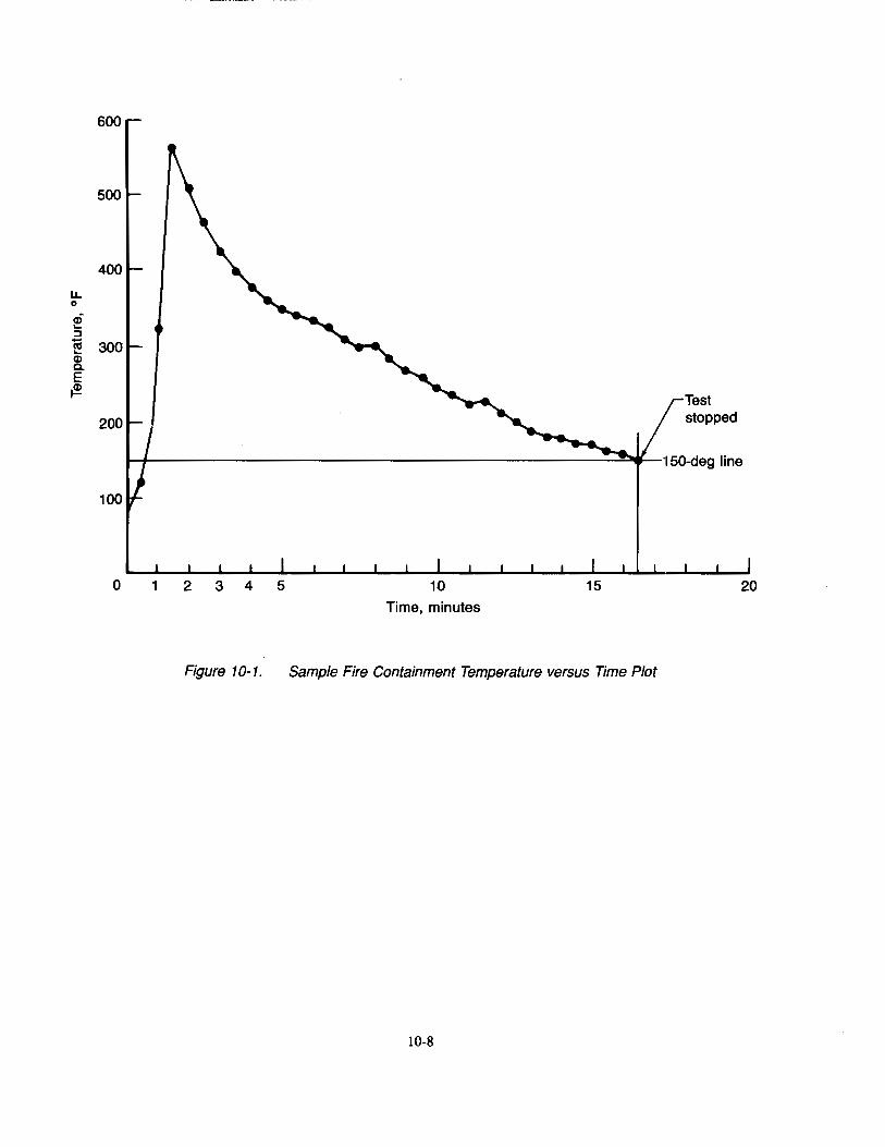
u. 0
(I) .... ~
~ (I) Q.
E ~
600
500
0 1 2 3 4 5 10 Time, minutes
15
Figure 10-1. Sample Fire Containment Temperature versus Time Plot
10-8
rTest stopped
20
11.1 Scope
Chapter 11 Powerplant Hose Assemblies Test
11.1.1 This test method is used to determine the fire resistance of high-temperature hose assemblie:s used in designated fire zones to damage due to flame and vibration for showing compliance with TSO C42, C53A, and C75.
11.1.2 The requirements and procedures of this test method vary according to hose materials and hose assembly application.
11.2 Definitions
11.2.1 Designated Fire Zone
A region of the aircraft such as engine and auxiliary power unit compartments designated to require fire detection and extinguishing equipment, and as appropriate the use of materials that are fire resistant or fireproof.
11.2.2 Fireproof
Per FAR Part 1, "in designated fire zones means the ability of materials or parts to withstand the heat from a severe fire of extended duration at least as well as steel in dimensions appropriate for their purpose."
Powerplant hose assemblies are demonstrated to be fireproof by meeting the requirements of this test for a flame exposure time of 15 min.
11.2.3 Fire Resistant
Per FAR Part 1, "with respect to fluid carrying lines, fluid system parts, wiring, air ducts, fittings, and powerplant controls means the capacity to perform the intended functions under the heat and other conditions likely to occur when there is a fire at the place concerned."
Powerplant hose assemblies are demonstrated to be fire resistant by meeting the requirements of this test for a flame exposure time of 5 min.
11.2.4 Class A Hose Assembly
A hose assembly capable of withstanding exposure to this fire test procedure for 5 min without failure (e.g., leaking circulating oil) per TSO C53a.
11.2.5 Class B Hose· Assembly
A hose assembly capable of withstanding exposure to this fire test procedure for 15 min without failure (e.g., leaking circulating oil) per TSO C53a.
11.2.6 Velometer
A device for measuring airflow velocity.'
11.2. 7 Photocell
An electronic device having output that varies in response to the intensity of incident visible light.
11.3 Apparatus
11.3.1 Test Burner
A modified gun-type conversion oil burner as described in Table 11-1 shall be used. The burner shall be calibrated to provide a minimum average flame temperature of 2,000°F (1 ,093°C) and a minimum heat input
1A device manufactured by Alnor Instrument Co., 7555 North Linder Ave., Skokie, IL 60077-3822, catalog number 01518, has been found satisfactory.
11-1
of 4,500 Btu/hr to the Btu heat transfer device described in Section 11.3.3.2, or 9.3 Btu/ft2-sec (10.6 W/cm2 )
as measured by a calorimeter described in Section 11.3.3.1.
11.3.1.1 Burner Extension
A stainless steel funnel extension fabricated in accordance with Figure 11-1 shall be used. The funnel shall have an oblong exit 6 in (152 mm) high by 11 in (279 mm) wide. The funnel shall be installed on the burner with the air tube shown in Figure 11-2.
11.3.1.2 Burner Fuel
SAE NO. 2 diesel, kerosene, or equivalent shall be used for burner fuel.
11.3.2 Thermocouples
A thermocouple rake containing at least five ANSI 22-gauge Chromel-Alumel (Type K) thermocouples sheathed in '1!6-in (1.6-mm) stainless steel or inconel tubes, or equivalent shall be provided. The thermocouples shall be aligned in a row 1.0 ± 0.1 in (25 ± 3 mm) apart.
11.3.3 Heat Flux Measuring Device(s)
One of the following devices shall be used to measure the heat flux density of the flame:
11.3.3.1 Calorimeter
A water-cooled calorimeter capable of measuring heat flux densities up to 15 Btu/ft2/sec (17 W/cm2 )
may be provided for burner calibration. A Hy-Cal model l300A total heat flux density calorimeter available from Hy-Cal Engineering, Santa Fe Springs, California, or equivalent has been found suitable.
11.3.3.2 Btu Heat Transfer Device
Figures 11-4 to 11-l 0 show fabrication details of an acceptable copper tube device2 used to measure heat flux density. The mercury thermometers shall be positioned in the mounting tubes so that the bottom of the bulb is within 'II6 in ( 1.6 mm) of the bottom of the passage in the heat transfer tube, see Figures ll-7 and 11-8.
11.3.3.2.1 Thermometers
11.3.4 Test Setup
Two glass scientific thermometers calibrated in 0.05°C (0.1 °F) increments, immersible thermocouples, or equivalent shall be provided for the heat transfer tube assembly.
A steel table measuring 60 in (1,524 mm) wide, 28 in (711 mm) deep, and 32 in (813 mm) high has been found acceptable. The vibrating mechanism and hood, described below, may be mounted on this table. See Figure ll-1 for an acceptable test setup.
11.3.4.1 Vibration Source
A means shall be provided to vibrate the hose assembly as shown in Figure 11-8 at 33 Hz with a total displacement of at least 1/s in (3.2 mm) i.e., with an amplitude of at least 1/t6 in (1.6 mm)).
11.3.4.2 Hood
A hood measuring 25 in (635 mm) wide and 25 in (635 mm) high has been found acceptable. The hood may be placed on the bench near the vibration source so that the vibrating fitting for the hose attachment is located 7 in (178 mm) behind the open front of the hood.
11.3.4.2.1 Fan
The hood shall have a fan installed on the rear to draw air through it at a velocity of 400 ft/min (203 cm/s) as measured by a velometer located at the position occupied by the hose assembly specimen during test.
2A satisfactory version of the woven copper fabric shown in Figure 11-5 is manufactured by Metal Textile Corp., Roselle, New Jersey.
11-2
11.3.4.2.2 Photocell
The hood may contain a photocell to detect a flareup resulting from burning oil due to a hose failure.
11.3.4.3 Automatic Shutdown System
An automatic shutdown system may be provided to terminate the test, by turning off the burner, vibrating mechanism, hood fan, and oil flow, if a flareup of burning oil escaping from a failed hose assembly is detected.
11.3.4.4 Temperature Measuring and Recording Equipment
A temperature sensing system shall be provided that includes a sufficient number of thermocouples to ensure that the specified temperature exists along the entire end fitting and along the hose for a distance of not less than 5 in (127 mm). The system shall include a recorder to monitor the flame temperature throughout the fire test duration3.
11.3.5 Oil Circulator and Heater
A device consisting of an oil tank with a temperature-controlled immersion heater and an electrical oil pump shall be provided if the hose assembly being tested must have oil pumped through the hose(s) during the test. The plumbing shall include appropriate flow indicators, pressure gauges, control and selector valves, and pressure relief valves.
11.3.5.1 Oil
11.4 Test Specimens
SAE No. 20 oil in accordance with Military Specification MIL-L-2104C or equivalent shall be provided and used in the oil circulator and heater to pump through the hose assembly test s.pecimen during test.
11.4.1 Prepare three specimens, 24 in (610 mm) in length, for the test.
11.4.2 The configuration of the hose test specimens shall be as used in service. A firesleeve may be added to the hose assembly if needed to enable the test specimens to withstand the fire test duration specified.4
11.5 Calibration
11.5.1 Place the thermocouple rake on the test stand at a distance of 4 in ( 102 mm) above the centerline of the burner extension. Connect the thermocouples to a stripchart recorder.
11.5.2 Light the burner, allow a 3-min warmup, and move the burner into test position.
11.5.3 Begin monitoring the temperatures indicated by the thermocouples after 3 min. Make adjustments as necessary to either the gas flow or the airflow to the burner in order to achieve a minimum average thermocouple reading of 2,000°F (1' 1 00°C).
11.5.4 Turn the burner off, move it out of test position, and remove the thermocouple rake.
11.5.5 Replace the thermocouple rake with the heat flux measuring device. Follow Section 11.5.5.1 if using a watercooled calorimeter for measuring heat flux. Follow Section 11.5.5.2 if using a Btu heat transfer device for this purpose.
11.5.5.1 If using the water-cooled calorimeter described in Section 11.3.3.1, place the calorimeter at the same distance as the thermocouple rake centered over the burner exit.
11.5.5.1.1 Light the burner, allow a 2-min warmup, and move the burner into test position.
3Permanent installation of temperature measuring thermocouples and continuous recorder has been added for better control of the flame temperature during calibration and test.
4If a firesleeve is required to be added for a hose type to pass the test, a firesleeve must be fitted to that hose type before it may be used in designated fire zones on an airplane.
11-3
11.5.5.1.2 Measure the heat flux density continuously or at intervals no greater than 10 sec. If the heat flux density is not at least 9.3 Btu/ft2-sec (10.6 W /cm2), readjust the burner to achieve the proper heat flux. If burner adjustments are necessary, remove the heat flux measuring device and repeat Sections 11.5.1 through 11.5.5.1.2.
11.5.5.2 If using the Btu heat transfer device described in Section 11.3.3.2, ensure the extemal surface of the copper tubing on the Btu heat transfer device is clean prior to measuring heat flUtx. Use fine steel wool to clean the copper tubing. Inspect the tubing bore for corrosion and/or scale accumulation and remove before each test. A .45-caliber pistol cleaning brush, or equivalent, with an extension has been found suitable for this purpose.
11.6 Procedure
11.5.5.2.1 The calibration setup is shown in Figure 11-11. Provide a 5 ft ( 1.5 m) constant head of water above the heat transfer device and a 2 ft (0.61 m) drop to the end of the tailpipe for adjustment of the water flow rate. Use a 1 gal (3.8 L) measuring container (a container and a weighing scale are also acceptable). Adjust the water flow rate to 500 lb/hr (227 kg/ hr) or 1 gal/min (3.8 L/min). Supply water at a temperature between 50° to 70°F (10° to 21°C).
11.5.5.2.2 Start the water flowing through the Btu heat transfer device. Center the heat transfer tube in the flame at the same location that a hose assembly would be placed for testing. Allow a 2-min warmup period to stabilize flame conditions before temperature measurements from the mercury thermometers are recorded.
11.5.5.2.3 After the warmup period, record the inlet and outlet temperatures every 30 sec for a 3-min period. Determine the rate of Btu increase of the water as follows:
Heat transfer= 146 x (T0 - T) watts (for Celsius) = 500 x (To - T) Btu/hr (for Fahrenheit)
where: T0
= temperature (C or F) at outlet Ti =temperature (C or F) at inlet
11.5.5.2.4 The heat rate output, as determined by the equation shown in Section 11.5.5.2.3, shall be a minimum of 4,500 Btu/hr. If the heat output from the burner is not above this minimum, make adjustments to the burner and repeat Sections 11.5.1 through 11.5.5.2 until the burner is within tolerance.
11.6.1 Specimen Mounting
Mount the hose assembly in the test setup to include at least one full 90-deg bend so that the pressure existing inside the hose will exert an axial force on the hose end fitting. Locate the hose assembly 4 in ( 102 mm) beyond the burner barrel extension so that the entire hose assembly end fitting and at least a minimum 5 in (127 mm) of the hose is exposed to the flame. Install the entire hose assembly inside the hood unless limited by the physical characteristics of the hose such as minimum bend radius, see Figure 11-1.
11.6.2 Preheat the oil in the oil tank to 200° ± 10°F (93° ± 6°C). Start the oil circulating pump and circulate the oil through the test hose assembly at a flow rate and pressure as specified by hose type, size and application. Pressures and flow rates are as shown in Table 11-2.5
11.6.3 Start the vibrating mechanism and observe the movement of the hose. Ensure that no whipping of the hose occurs.
11.6.4 Start the hood air fan and begin monitoring the thermocouple recorder.
11.6.5 Start the burner. Periodically observe the recorded temperature to ensure that the required minimum flame temperature Of 2,000°F (1 ,093 °C) is maintained. I
5Flow rate values given in Table 11-2 were derived from TSO C53A. Flow rates used for the test should be minimum flow rates given for the actual installation, if known.
11-4
11.6.6 If a ftareup of burning oil occurs due to a hose failure, terminate the test.
11.6.7 After the required test duration has been reached (i.e., 5 min for Class A hose assemblies and 15 min for Class B hose assemblies), terminate the test.
11.6. 7.1 Stop the burner.
11.6.7.2 Relieve the oil pressure in the hose assembly.
11.6.7.2 Turn off the temperature recorder.
11.7 Report
11.7 .1 Fully identify the hose configuration, including the assembly and fittings, and the Class for which it is being tested.
11.7.2 Report whether there were any ftareups of leaking oil, and any other pertinent observations.
11.7.3 Report whether the hose configuration met the requirements of Class A or Class B Assemblies.
11.8 Requirements
11.8.1 Class A Hose Assembly
A Class A hose assembly shall withstand the test procedure described in Section 6 for at least 5 min without leaking circulating oil.
11.8.2 Class B Hose Assembly
A Class B hose assembly shall withstand the test procedure described in Section 6 for at least 15 min without leaking circulating oil.
11-5
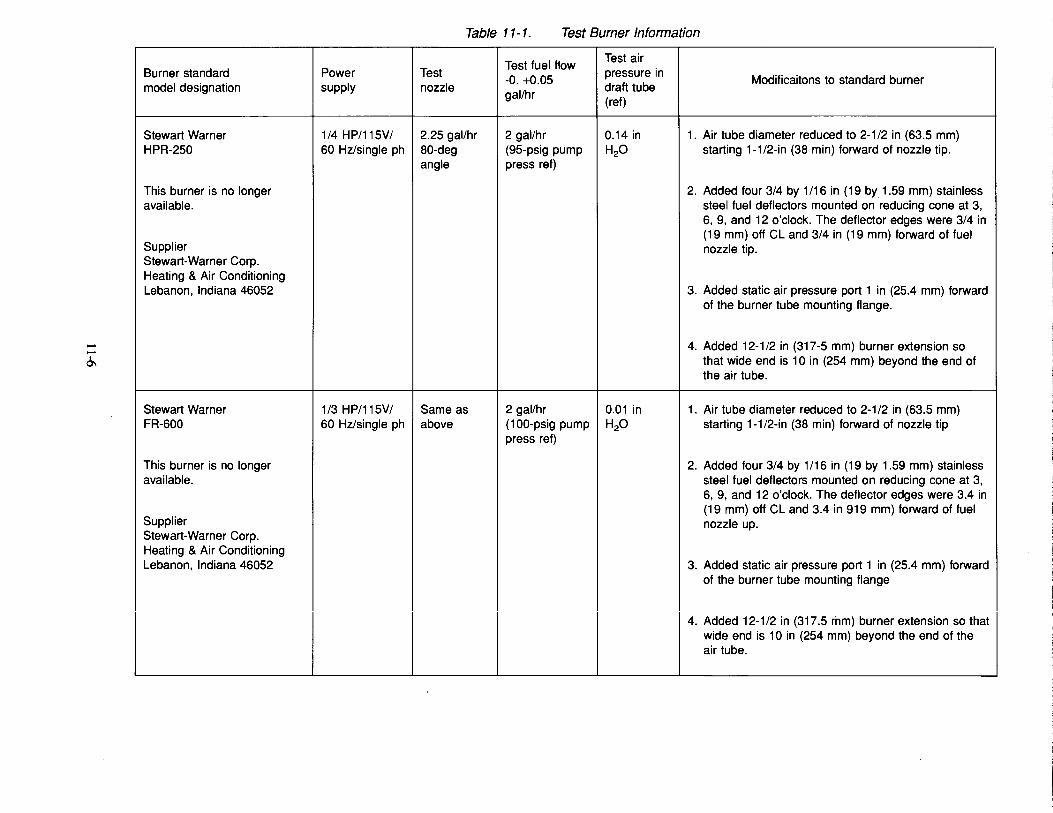
--0.,
Table 11-1. Test Burner Information
Test fuel flow Test air . Burner sta~dar~ Power Test -0. +0.05 pressure In Modificaitons to standard burner model des1gnat1on supply nozzle l/h draft tube
ga r (ref)
Stewart Warner 1/4 HP/115V/ 2.25 gal!hr 2 gal/hr 0.14 in 1. Air tube diameter reduced to 2-1/2 in (63.5 mm) HPR-250 60Hz/single ph 80-deg (95-psig pump H20 starting 1-1/2-in (38 min) forward of nozzle tip.
angle press ref)
This burner is no longer 2. Added four 3/4 by 1/16 in (19 by 1.59 mm) stainless 1
available. steel fuel deflectors mounted on reducing cone at 3, ' 6, 9, and 12 o'clock. The deflector edges were 3/4 in (19 mm) off CL and 3/4 in (19 mm) forward of fuel
Supplier nozzle tip. Stewart-Warner Corp. Heating & Air Conditioning Lebanon, Indiana 46052 3. Added static air pressure port 1 in (25.4 mm) forward
of the burner tube mounting flange.
4. Added 12-1/2 in (317-5 mm) burner extension so that wide end is 10 in (254 mm) beyond the end of the air tube.
Stewart Warner 1/3 HP/115V/ Same as 2 gal/hr 0.01 in 1. Air tube diameter reduced to 2-1/2 in (63.5 mm) FR-600 60Hz/single ph above (100-psig pump H20 starting 1-1/2-in (38 min) forward of nozzle tip
press ref)
This burner is no longer 2. Added four 3/4 by 1/16 in (19 by 1.59 mm) stainless available. steel fuel deflectors mounted on reducing cone at 3,
6, 9, and 12 o'clock. The deflector edges were 3.4 in (19 mm) off CL and 3.4 in 919 mm) forward of fuel
Supplier nozzle up. Stewart-Warner Corp. Heating & Air Conditioning Lebanon, Indiana 46052 3. Added static air pressure port 1 in (25.4 mm) forward
of the burner tube mounting flange
I I I I I 14. Added 12-112 ;n (317.5 mm) bumer e>rtens;on so that wide end is 10 in (254 mm) beyond the end of the air tube.
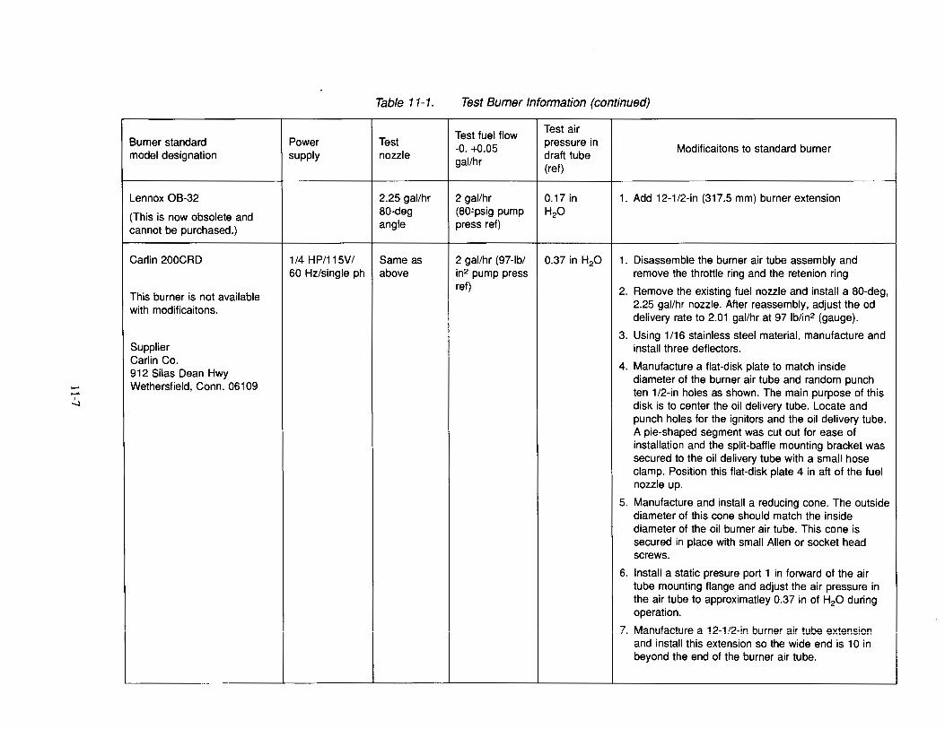
Table 11-1. Test Burner Information (continued)
Test fuel flow Test air
Burner standard Power Test -0. +0.05
pressure in Modificaitons to standard burner
model designation supply nozzle gal/hr
draft tube (ref)
Lennox OB-32 2.25 gal/hr 2 gal/hr 0.17 in 1. Add 12-112-in (317.5 mm) burner extension
(This is now obsolete and 80-deg (80~psig pump H20
cannot be purchased.) angle press ref)
Carlin 200CRD 1/4 HP/115V/ Same as 2 gal/hr (97-lb/ 0.37 in H20 1. Disassemble the burner air tube assembly and 60 Hz/single ph above in2 pump press remove the throttle ring and the retenion ring
ref) 2. Remove the existing fuel nozzle and install a 80-deg, This burner is not available 2.25 gal!hr nozzle. After reassembly, adjust the od with modificaitons. delivery rate to 2.01 gal/hr at 97 lb/in2 (gauge).
3. Using 1/16 stainless steel material, manufacture and Supplier install three deflectors.
--~ Carlin Co.
4. Manufacture a flat-disk plate to match inside 912 Silas Dean Hwy
diameter of the burner air tube and random punch Wethersfield, Conn. 06109
ten 1/2-in holes as shown. The main purpose of this disk is to center the oil delivery tube. Locate and punch holes for the ignitors and the oil delivery tube. A pie-shaped segment was cut out for ease of installation and the split-baffle mounting bracket was secured to the oil delivery tube with a small hose clamp. Position this flat-disk plate 4 in aft of the fuel nozzle up.
5. Manufacture and install a reducing cone. The outside diameter of this cone should match the inside diameter of the oil burner air tube. This cone is secured in place with small Allen or socket head screws.
6. Install a static presure port 1 in forward of the air tube mounting flange and adjust the air pressure in the air tube to approximatley 0.37 in of H20 during operation.
?. Manufacture a 12-1/2-in burner air tube extension and install this extension so the wide end is 10 in beyond the end of the burner air tube.
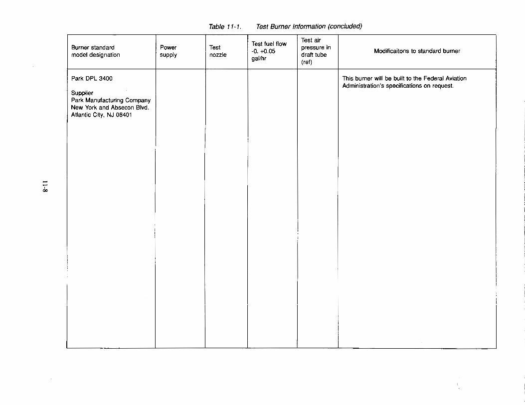
Table 11-1. Test Burner Information (concluded)
Test fuel flow Test air
Burner standard Power Test -0. +0.05
pressure in Modificaitons to standard burner
model designation supply nozzle gal!hr
draft tube (ref)
Park DPL 3400 This burner will be built to the Federal Aviation Administration's specifications on request. i
I
Supplier Park Manufacturing Company New York and Absecon Blvd. Atlantic City, NJ 08401
--I 00
--
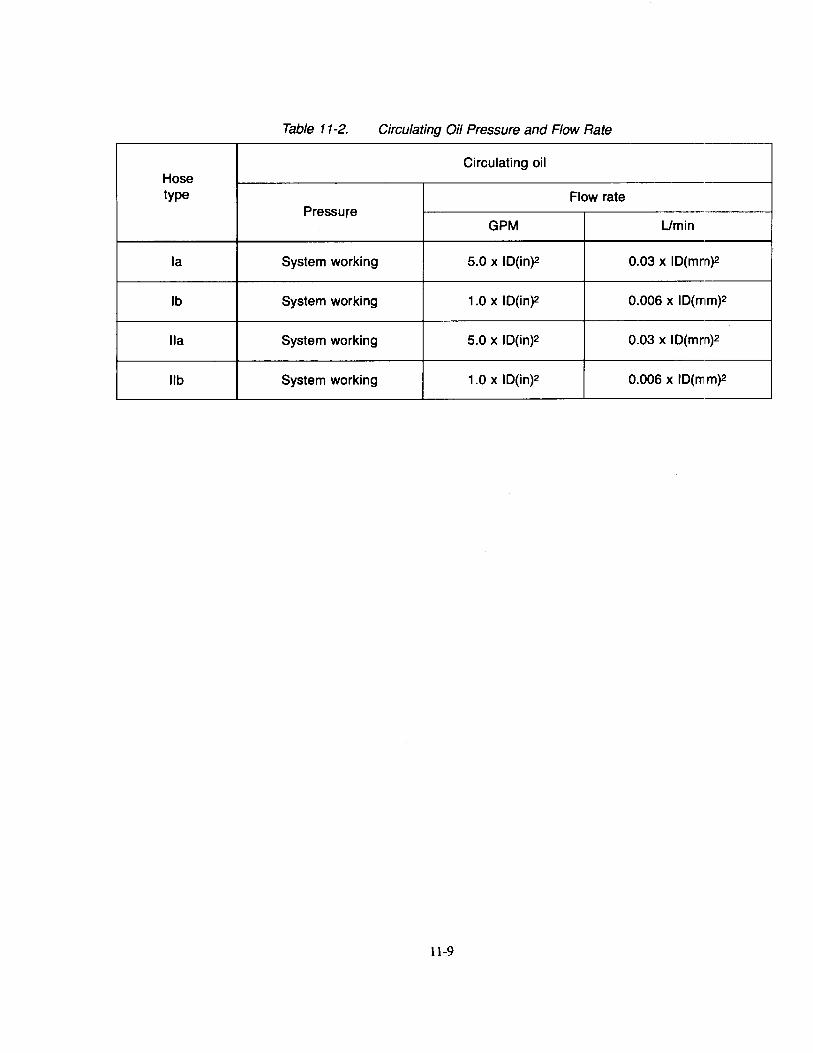
Table 11-2. Circulating Oil Pressure and Flow Rate
Circulating oil Hose type Flow rate
Pressure GPM Umin
Ia System working 5.0 x ID(in)2 0.03 x ID(mm)2
lb System working 1.0 x ID(in)2 0.006 x ID(mm)2
II a System working 5.0 x ID(in)2 0.03 x ID(mm)2
lib System working 1.0 x ID(in)2 0.006 x ID(mm)2
11-9
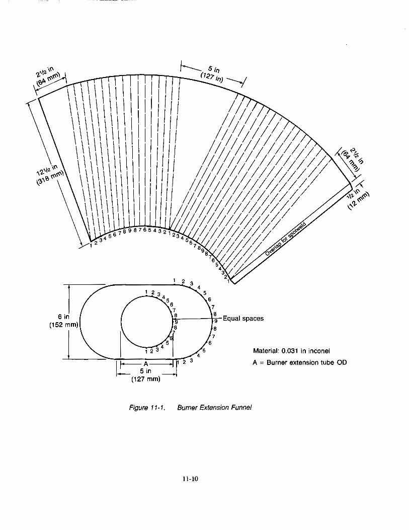
Material: 0.031 in inconel
A = Burner extension tube OD
Figure 11-1. Burner Extension Funnel
11-10
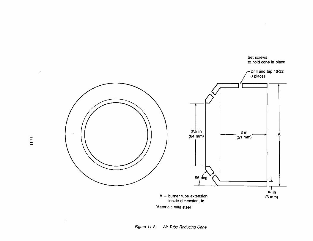
--I -2112 in
(64 mm)
A = burner tube extension inside dimension, in
Material: mild steel
Figure 11-2. Air Tube Reducing Cone
Set screws to hold cone in place
2in (51 mm)
____ ___.1.
1/4 in (6 mm)
A

specimen
Thermocouples
Photocell
Extension Funnel
r------1- Vibrating mechanism
Figure 11-3. Hose Assemblies Test Setup
11-12
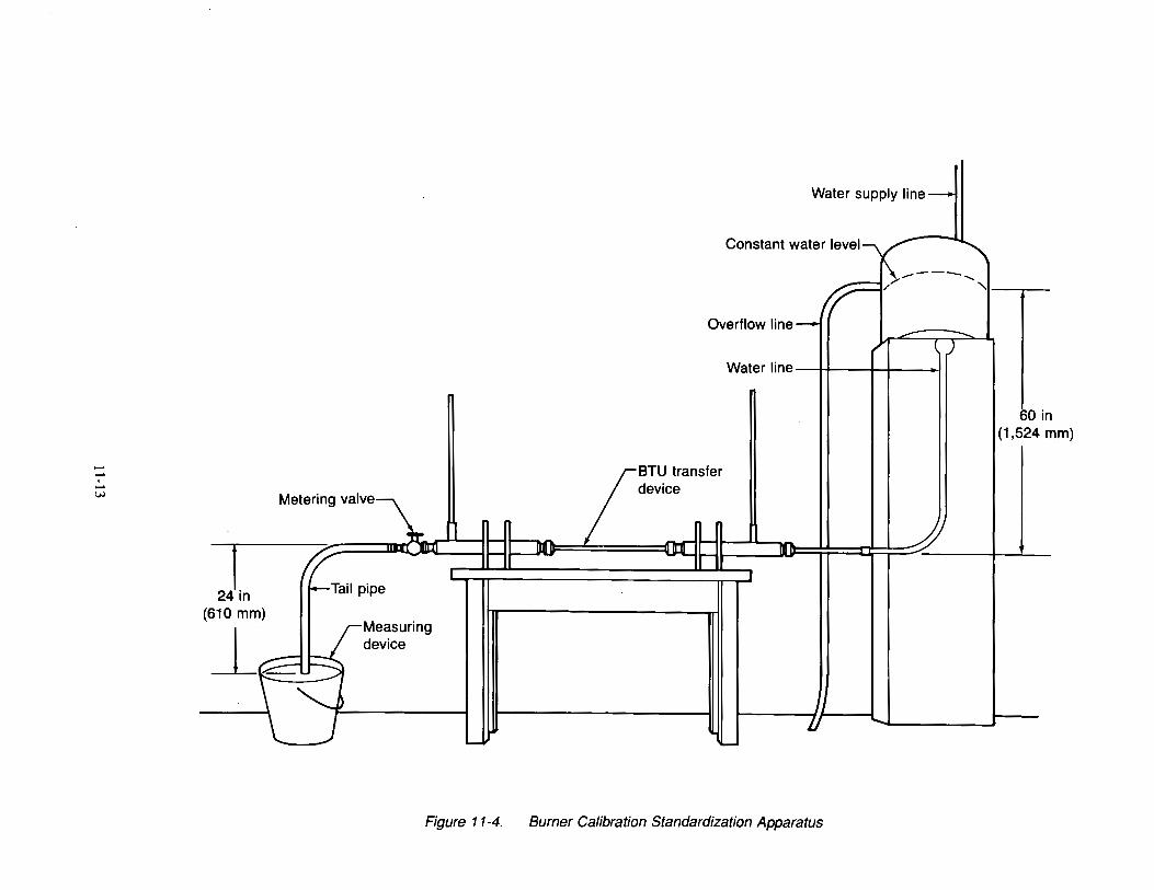
--I -w Metering valve~
1 1-
!? liiii 1-
l
24 In 1---Tail pipe
(610 mm)
j__ J·Measuring device
--::3 ~
1......1
Figure 11-4.
:j --- ----- I' ""'
\-----r// ........... Overflow line-
.£_ ....... ~ ( )
Water line
60 i (1 ,524 mm)
~~TU transfer device
~lllf jl . ~~ l'lr
l
7J ...... ........
Burner Calibration Standardization Apparatus
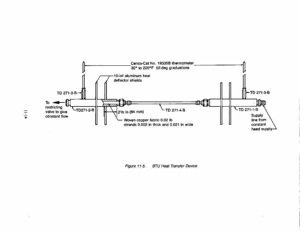
--I -~
n. Cenco-Cat No. 193358 thermometer •0 ~ 30° to 220°F 02-deg graduations ~
~---...-1 O-in2 aluminum heat deflector shields
TO 271-3-B
To restricting valve to give constant flow
T0271-2-B TO 271-4-B
Woven copper fabric 0.02 lb strands 0.002 in thick and 0.021 in wide
Figure 11-5. BTU Heat Transfer Device
TO 271-3-B
supply line from constant head supply
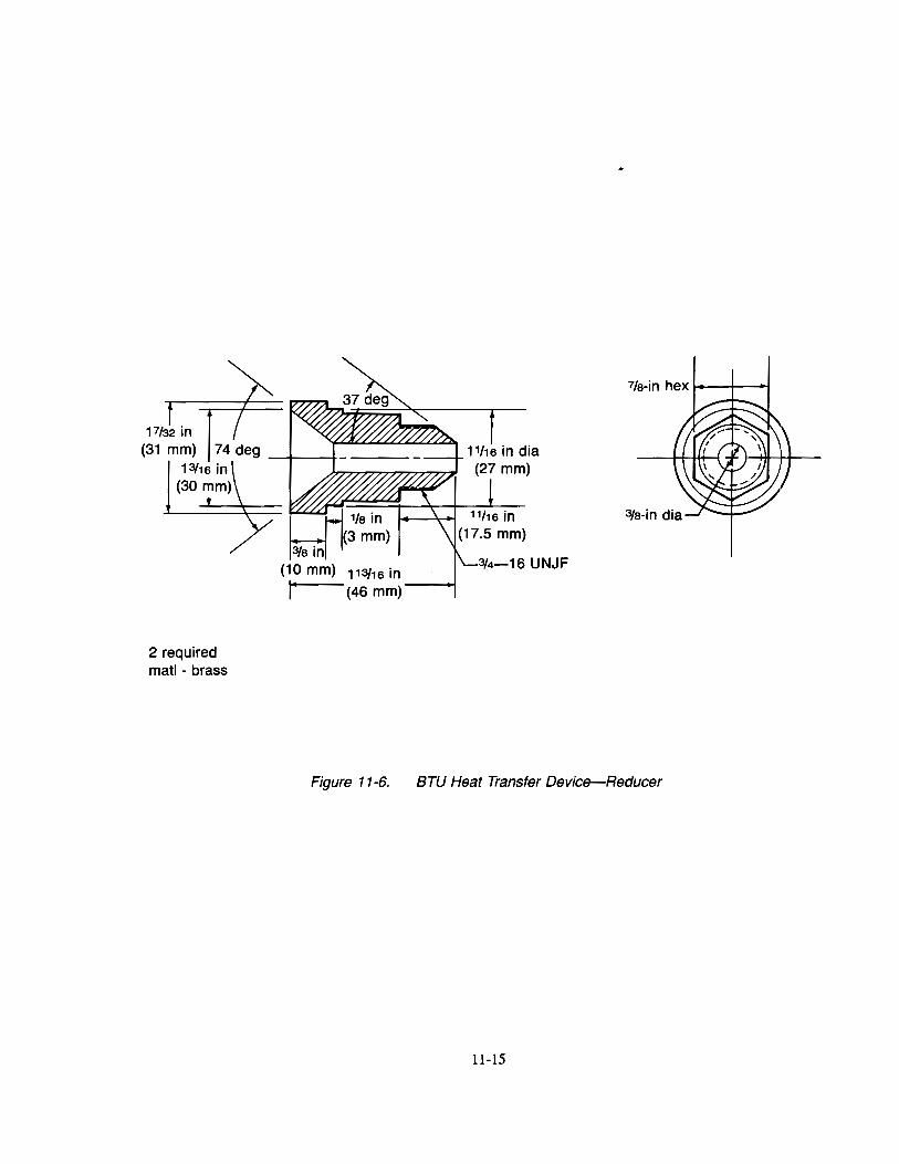
2 required matl- brass
Figure 11-6. BTU Heat Transfer Device-Reducer
11-15
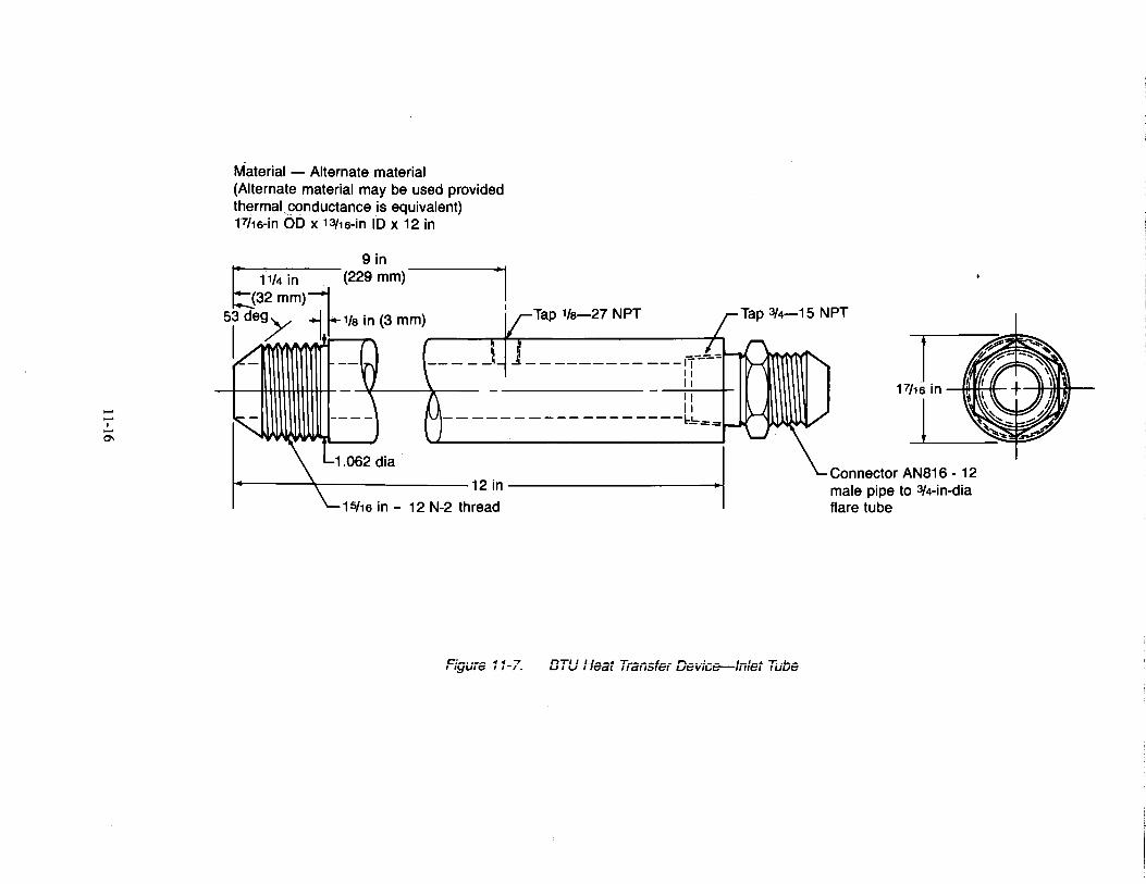
--I -0\
Material - Alternate material (Alternate material may be used provided thermal ,conductance is equivalent) Fhs-in 00 x 13/1s-in 10 x 12 in
9in 11/4 in (229 mm) -1
(32 mm)--:1 53
1
dO~ 1.1-'/s in (3 mm) rq-Tap 1/a-27 NPT
~(' ~-_n ------------11
1.062 dia
II II II II
------------------~==
12in ·I 15f1s in- 12 N-2 thread
c:-.... _ ., ., 7 I I!::JUir::> I 1-f. BTU Heat T;ansfe; Device--Inlet Tube
Connector AN816- 12 male pipe to 3/4-in-dia flare tube
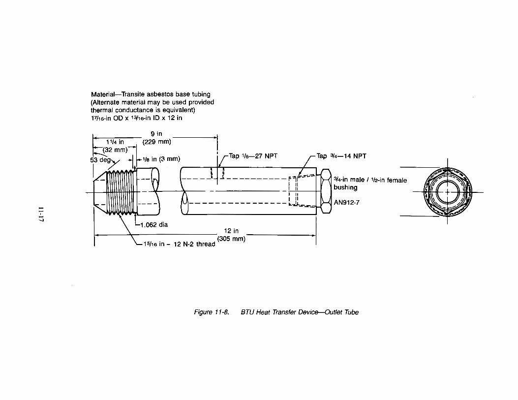
-I --...1
Material-Transite asbestos base tubing (Alternate material may be used provided thermal conductance is equivalent) Fhs-in 00 x 13/1s-in 10 x 12 in
9in 11/4 in (229 mm) "I
(32 mm)--:1 53 d~ 1.1-"'18 in(~ mm) j{Tap '18-27 NPT I~ r_ ___ _! -'----------f'i~
I II I II
--- I II --------- I II ---- a..-IL
1.062 dia 12 in
15f1s in- 12 N-2 thread (305 mm)
--=-~,_;;;;;;;
3/4-in male I 112-in female bushing
AN912-7
Figure 11-8. BTU Heat Transfer Device-Outlet Tube
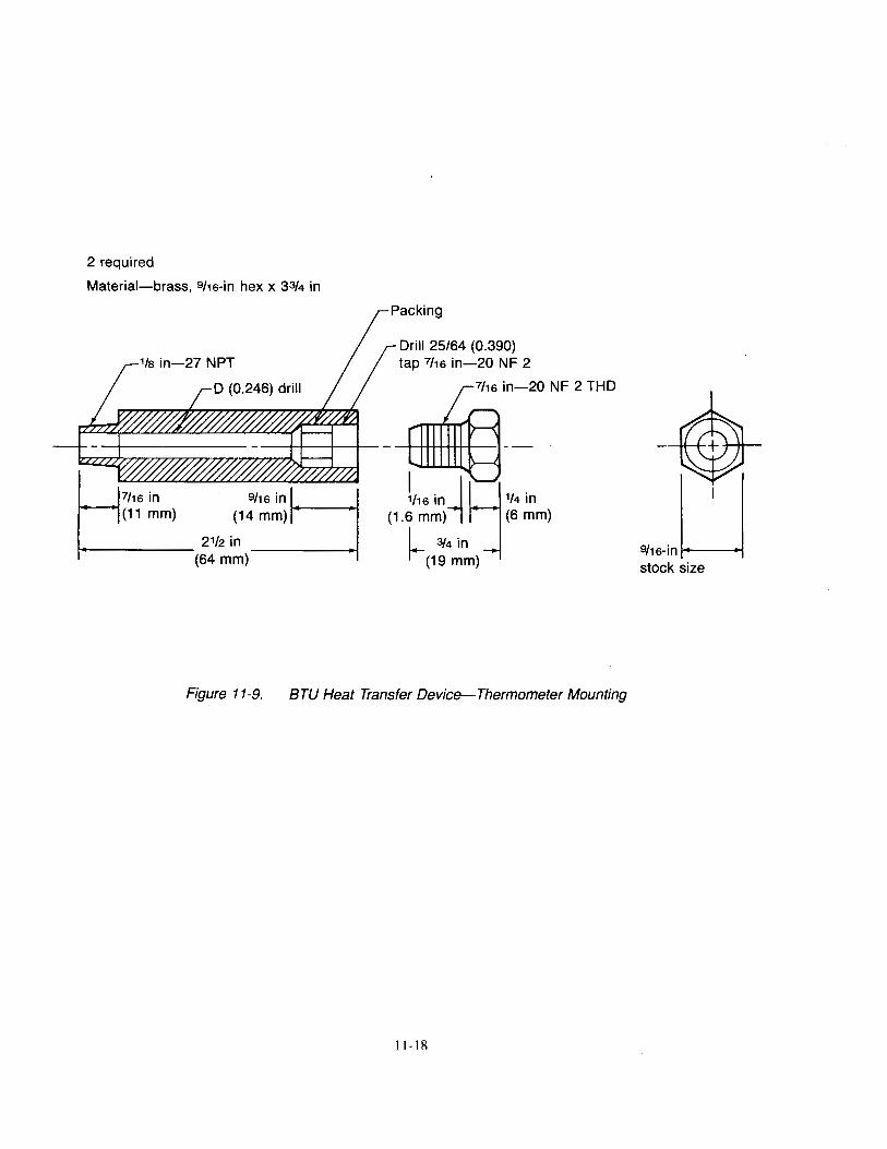
2 required
Material-brass, 9f1s-in hex x 33/4 in
(1:~~~ 2112 in t------
(64 mm)
Drill 25/64 (0.390) tap 7f1s in-20 NF 2
7f1s in-20 NF 2 THD
Figure 11-9. BTU Heat Transfer Device-Thermometer Mounting
11-18
9f ... 1~J stock size
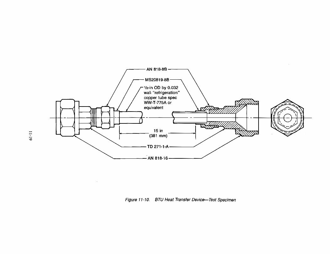
-I ~ -1.0 ~
r----AN 818-86---,
MS20819-8B
112-in OD by 0.032 wall "refrigeration" copper tube spec WW-T-775A or equivalent
15 in (381 mm)
TO 271-1-A
AN 818-16
·I
Figure 11-10. BTU Heat Transfer Device-Test Specimen

This page intentionally left blank
ll-20

12.1 Scope
Chapter 12 Powerplant Fire Penetration Test
12.1.1 This test method is intended to determine the capability of components and constructions to control the passage of fire or its effects in powerplant (engine) compartments and thereby to prevent additional hazard to the aircraft in the event of fire. 1
12.1.2 This test is used to show compliance with FAR 25.867, 25.865, 25.1191, and 25.1193.
12.2 Definitions
12.2.1 Firewall
A structure designed to prevent a hazardous quantity of air, fluid, or flame from exiting a fire zone in which a fire has erupted and causing hazard to the aircraft. Firewalls must be fireproof.
12.2.2 Fireproof
Per FAR Part 1, "in designated fire zones means the ability of materials or parts to withstand the heat from a severe fire of extended duration at least as well as steel in dimensions appropriate for their purpose."
Materials or parts are demonstrated to be fireproof by meeting the requirements of this test for a flame exposure time of 15 min.
12.2.3 Fire Resistant
Per FAR Part I, "with respect to fluid carrying lines, fluid system parts, wiring, air ducts, fittings, and powerplant controls means the capacity to perform the intended functions under the heat and other conditions likely to occur when there is a fire at the place concerned."
Materials or parts are demonstrated to be fire resistant by meeting the requirements of this test for a flame exposure time of 5 min.
12.2.4 Heat Flux Density
The rate of thermal energy transferred per unit area, expressed here in units of Btu/ft2-sec or W/cm2.
12.3 Apparatus
12.3.I Test Burner
The burner shall be a modified gun-type oil burner2 such as: Park Model DPL 3400, Stewart Warner HPR-250 or FR-600, Lennox OB-32, or Carlin 200 CRD. The burner shall be calibrated to provide a minimum average flame temperature of 2,000°F (1,093°C) and a minimum heat transfer rate of 4,500 Btu/hr to the Btu Heat Transfer Device described in Section 1.3.3.I, or 9.3 Btu/ft2-sec (10.6 W/cm2) as measured by a calorimeter described in Section I.3.3.2.
I2.3.1.1 Burner Extension
A stainless steel funnel extension fabricated in accordance with Figure 1I-I shall be used. The funnel shall have an oblong exit 6 in (152 mm) high by II in (279 mm) wide. The funnel shall be installed on the burner with the air tube shown in Figure II-2.
I2.3.1.2 Burner Fuel
SAE No. 2 diesel, kerosene, or equivalent shall be used for burner fuel.
'Advisory Circular AC 20-I35, "Powerplant Installation and Propulsion System Component Fire Protection Test Methods, Standards and Criteria", February 6, I990.
2An SAE AS401B Propane Burner is also acceptable provided the temperature profile and heat flux density conform to the requirements specified in this test method.
12-1
12.3.2 Thermocouples
A thermocouple rake containing at least five ANSI 22-gauge Chromel-Alumel (Type K) thermocouples sheathed in 1/16-in (1.6-mm) stainless steel or inconel tubes or equivalent shall be provided.3 The thermocouples shall be aligned in a row 1.0 +/0.1 in (25 +/2 mm) apart.
12.3.3 Heating Rate Measuring Device(s)
One of the following devices shall be used to measure the heating rate of the flame:
12.3.3.1 Btu Heat Transfer Device
A Btu heat transfer device as described in Chapter 11.0, "POWER PLANT HOSE ASSEMBLIES TEST," Figures 11-4 to 1 I -10, in this handbook may be used.
12.3.3.2 Calorimeter
A calorimeter capable of measuring heat flux densities up to 15 Btu/ft2-sec (17 W/cm2) may be used. A Hy-Cal model 1300A total heat flux density calorimeter available from Hy-Cal Engineering, Santa Fe Springs, California, or equivalent with water cooling has been found suitable.
12.3.4 Test Stand
A test stand shall be provided to maintain the position of the thermocouple rake, calorimeter or Btu heat transfer device, and test specimen. The test stand shall include a provision for either moving the burner out of test position or moving the test specimen into/out of test position. The test stand shall also include a provision for positioning the thermocouple rake or burner extension is parallel to the burner face with the thermocouple junctions on the diameter or major axis of the burner or burner extension. A suitable test setup is shown in Figure 12-1.
12.3.5 Timer
A stopwatch or other device, calibrated and graduated to the nearest 1 sec, shall be used to measure the time of application of the burner flame.
12.4 Test Specimens
12.4.1 Specimen Selection
Test specimens shall be actual or simulated aircraft hardware, including all combustible materials that are applied to the actual structure in use. Heat flow paths and heat sinks shall be as in the production configuration being certified.
12.4.2 Specimen Size
In general, specimen size shall be 24 in by 24 in (610 mm by 610 mm). Larger specimens shall be used if required to accommodate a critical design feature of the component. Smaller specimens 10 in by 10 in (254 mm by 254 mm) may be used if all design features are included and the specimen is representative of the intended use. For a smaller specimen, the backside of the specimen shall be protected from exposure to the flame.
12.5 Conditioning
12.5.1 Specimen Conditioning
Specimens containing nonmetallic components shall be preconditioned if required to simulate the aircraft environment.
3Thermocouples may be either grounded or ungrounded depending on the type of data system used to monitor thermocouple output. One condition may generate more interference with instrumentation than the other.
12-2
12.6 Calibration
12.6.1 Place the thermocouple rake on the test stand such that the rake will be above the centerline of the burner or burner extension exit plane when the burner is in calibration position.4 Connect the thermocouples to a suitable recorder.
12.6.2 Light the burner, allow at least a 5-min warmup, and move the burner into calibration see section 12.3.4 position.5
12.6.3 Begin monitoring the temperatures indicated by the thermocouples after 5 min. Make adjustments as necessary to either the fuel flow or the airflow to the burner in order to achieve a minimum average thermocouple reading of 2,000°F (l ,093°C).
12.6.4 Tum the burner off or move it out of calibration position, and remove the thermocouple rake.
12.6.5 Replace the thermocouple rake with the heat flux density measuring device. Follow Section 1.6.5.1 if using a water-cooled calorimeter for measuring heat flux density. Follow Section 1.6.5.2 if using a Btu Heat Transfer Device for this purpose.
12.6.5.1 If using the water-cooled calorimeter described in Section 1.3.3.2 place the calorimeter at the same distance as the thermocouple rake centered over the burner exit.6
12.6.5.1.1 Light the burner, allowing at least a 2-min warm up, and move the burner into calibration position.
12.6.5.1.2 Measure the heat flux density continuously or at intervals no greater than 10 sec. If the heat flux density is not at least 9.3 Btu/ft2-sec (10.6 W/cm2) over a 1-min period, readjust the burner to achieve the proper heat flux density. If burner adjustments are necessary, remove the heat flux measuring device and repeat Sections 12.6.1 through 12.6.5.1.2.
12.6.5.2 If using the Btu heat transfer device described in Section 1.3.3.2, ensure the external surface of the copper tubing on the Btu heat transfer device is clean prior to measuring heat flux. Use fine steel wool to clean the copper tubing. Inspect the tubing bore and remove any corrosion and/or scale accumulation before each test. A .45-caliber pistol cleaning brush, or equivalent, with an extension has been found suitable for this purpose.
12.6.5.2.1 The calibration setup is shown in Figure 11-4. Provide a 5-ft (l.Sm) constanlt head of water above the heat transfer device and a 2-ft (0.61m) drop to the end of the tailpipe for adjustment of the water flow rate. Use a 1-gal (3.8 L) measuring container (a container and a weighing scale are also acceptable). Supply water at a temperature of 50' to 70°F (10° to 21 °C). Adjust the water flow rate to 500 lb/hr (227 kg/hr) or 1 gal/min (3.8 L/min).
12.6.5.2.2 Start the water flowing through the Btu heat transfer device. Center the heat transfer tube in the flame at the same location that the specimen will be placed for testing. Allow at least a 2-min warmup period to stabilize flame conditions before temperature measurements from the thermometers are recorded.
4 If using one of the conversion oil burners described in Section 1.1 for this test, the distance used to position the rake, heat flux measuring device, and test specimen shall be 4 in from the burner cone exit. If the burner used is an SAE AS401B Propane Burner, the distance used to position the thermocouple rake, etc. may be as close as 2 in from the burner face exit in order to achieve the temperature and heat flux density specified in this test procedure.
5If using anSAE AS401B Propane burner, the flame is not turned off during calibration or test setup. Most test facilities using this burner have provisions for moving the burner in and out of test position. If using a conversion oil burner, most facilities tum the burner on and off to change specimens and calibration equipment. If the burner is turned off at any time, it shall be warmed up for a 2-min period before testing or taking calibration measurements.
6Qperating the calorimeter without water running through it will permanently damage the calorimeter.
12-3
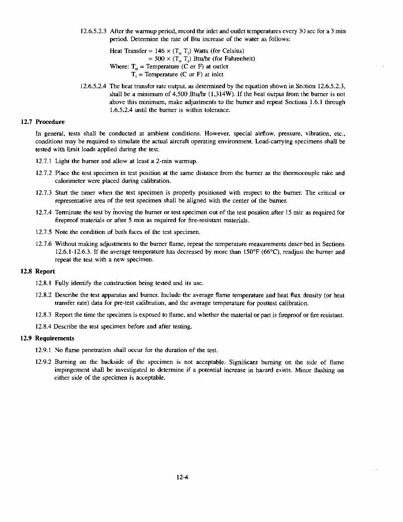
12.7 Procedure
12.6.5.2.3 After the warmup period, record the inlet and outlet temperatures every 30 sec for a 3 min period. Determine the rate of Btu increase of the water as follows:
Heat Transfer= 146 x (T0
T) Watts (for Celsius) = 500 X (T0 T) Btu/hr (for Fahrenheit)
Where: T 0
= Temperature (C or F) at outlet T; = Temperature (C or F) at inlet
12.6.5.2.4 The heat transfer rate output, as determined by the equation shown in Section 12.6.5.2.3, shall be a minimum of 4,500 Btu/hr (1,314W). If the heat output from the burner is not above this minimum, make adjustments to the burner and repeat Sections 1.6.1 through 1.6.5.2.4 until the burner is within tolerance. '
In general, tests shall be conducted at ambient conditions. However, special airflow, pressure, vibration, etc., conditions may be required to simulate the actual aircraft operating environment. Load-carrying specimens shall be tested with limit loads applied during the test.
12.7.1 Light the burner and allow at least a 2-min warmup.
12.7.2 Place the test specimen in test position at the same distance from the burner as the thermocouple rake and calorimeter were placed during calibration.
12.7.3 Start the timer when the test specimen is properly positioned with respect to the burner. The critical or representative area of the test specimen shall be aligned with the center of the burner.
12.7.4 Terminate the test by moving the burner or test specimen out of the test position after 15 min as required for fireproof materials or after 5 min as required for fire-resistant materials.
12.7.5 Note the condition of both faces of the test specimen.
12.7.6 Without making adjustments to the burner flame, repeat the temperature measurements described in Sections 12.6.1-12.6.3. If the average temperature has decreased by more than 150°F (66°C), readjust the burner and repeat the test with a new specimen.
12.8 Report
12.8.1 Fully identify the construction being tested and its use.
12.8.2 Describe the test apparatus and burner. Include the average flame temperature and heat flux density (or heat transfer rate) data for pre-test calibration, and the average temperature for posttest calibration.
12.8.3 Report the time the specimen is exposed to flame, and whether the material or part is fireproof or fire resistant.
12.8.4 Describe the test specimen before and after testing.
12.9 Requirements
12.9.1 No flame penetration shall occur for the duration of the test.
12.9.2 Burning on the backside of the specimen is not acceptable. Significant burning on the side of flame impingement shall be investigated to determine if a potential increase in hazard exists. Minor flashing on either side of the specimen is acceptable.
12-4
To control valve Vibrator (as required)
Pi tot-static probes
t~..,~~A~i~r ~flo~w~=======::[]:=i:.=====;f:i===~J~ Air exhaust
Air inlet Test specimen
(as required) Test position
Burner , ..... , _ _,.14---~l- Burner pivot
Burner test position track
Figure 12-1. Firewall Penetration Test Setup
12-5

This page intentionally left blank
12-6
Chapter 13 Test for Electrical Connectors Used in Firewalls
13.1 Scope
13.1.1 This test method is intended for use in determining the resistance of high-temperature electrical connectors used in fire zones to damage due to flame and vibration according to the requirements of FAR 23.1192, FAR 25.1191, FAR 27.1191, FAR 29.1191, FAR 25.863, FAR 25.865. FAR 25.867. FAR 25.1201, and FAR 25.1203.
13 .1.2 This test is used to evaluate the capability of wired, electrical, firewall connectors to prevent flame from passing to the protected side of the firewall. This test also provides a means to evaluate the connectors ability to sustain a minimum current of 1A for a limited period of time.
13.1.3 It is suggested that each connector type be tested in three sizes: 22-19, 14-7, and 12-3. Each connector size shall be tested separately.
13.2 Definitions
13.2.1 Firewall A structure designed to prevent a hazardous quantity of air, fluid, or flame from exiting a designated fire zone in which a fire may erupt, and causing additional hazard to the aircraft.
13.2.2 Firewall Connector
An electrical connector designed for installation in the firewall.
13.3 Apparatus
13.3.1 Simulated Firewall
A piece of steel 10 in (254 mm) by 10 in (254 mm) by 0.063 in (1.6 mm) thick to simulate a firewall shall be provided for each of the three connector sizes. A hole shall be drilled in the center of each piece appropriate to the respective connector size. If the simulated steel firewall does not adequately represent the actual application, a test of the proposed configuration may be required.
13.3.2 Burner{forch
A burner/torch, I modified to produce and maintain a minimum flame temperature of 2,000°F (1 ,093°C) shall be provided.
13.3.2.1 Burner Fuel
Propane gas fuel of 99% minimum purity shall be used, with a gas flow rate equivalent to 33,000 to 37,000 Btu/hr.
13.3.3 Power Supply (electrical, ac)
A center-tapped transformer shall be provided that is capable of producing a potential between 200V and 260V (ac) at 400Hz or 60Hz and delivering a current of at least 2A.
13.3.4 Power Supply (electrical, de)
A power source shall be provided that is capable of producing a potential of 28V (de) and a current between 5A and 150A.
13.3.5 Current Indicator
A multirange ammeter shall be provided that is capable of measuring de currents between 5A and 150A2 with an accuracy of 1% of full scale.
1An SAE AS401 Propane Burner or equivalent has been found acceptable.
2Choose the appropriate range of the ammeter to measure the test current. The appropriate range shall show the current in the middle one-third of the scale.
13-1
13.3.6 Vibration Source
A means shall be provided to vibrate the test fixture vertically at 33 Hz with a total excursion of 0.14 in (3.6 mm).
13.3.7 Gas flowmeter
A gas flowmeter shall be provided to measure the fuel flow to the burner/torch.
13.3.8 Temperature Measuring and Recording Equipment
A temperature sensing system shall be provided that includes a thermocouple and a stripchart recorder to monitor the flame temperature.
13.3.8.1 Thermocouple
An ANSI 22-gauge Chromel-Alumel (Type K) thermocouple sheathed in a Yt6 in (1.6 mm) stainless steel or inconel tube shall be provided.
13.3.9 High Temperature tape
High temperature tape (19 to 25 mm) wide shall be provided in sufficient length to wrap over the connector and wire bundles. 3 See Section 13.4.2.1.
13.3.10 Test Fixture
A test fixture and setup such as is shown in Figure 13-3, including a cable clamp to stabilize the wire bundleconnector interface during the test, shall be provided.
13.3.11 Timer
A stopwatch or other device, calibrated and graduated to the nearest 1 sec, shall be used to measure the time of application of the burner flame.
13.4 Test Specimens
13.4.1 Specimen Number
Prepare at least three specimens for each connector shell size to be tested.
13.4.2 Specimen Preparation
Clean all oil, grease, dirt, and other foreign material from the specimens.
13.4.2.1 Wrap the plug and receptacle wire bundle with the high temperature tape over the art~a to be located under the cable clamp that is used to stabilize the wire bundle-connector interface during flame/ vibration application. This area is a distance of 7.9 ±0.2 in (200 ±5 mm) from the connector backshell. See Figure 13-1 for details.
13.4.2.2 Connect the individual wires through the connector such that the circuit will be closed. Ensure that the connector shell is grounded during the test.
13.5 Procedure
13.5.1 Test Setup
Mount the simulated firewall on the vibration equipment table. Mount the connector that has been wired, mated, and prepared as described in Sections 13.4.2.1 and 13.4.2.2, in the center of the simulated firewall test fixture.
13.5.1.1 Support the wire bundle, using clamps to a stationary structure, at a distance of 7.9 ::!:0.2 in (200 ±5 mm) from the connector backshell on each side of the connector to protect from vibration.
13.5.1.2 Ensure that the connector shell is well grounded prior to starting the test.
3Untreated fiberglass tape has been found satisfactory.
13-2
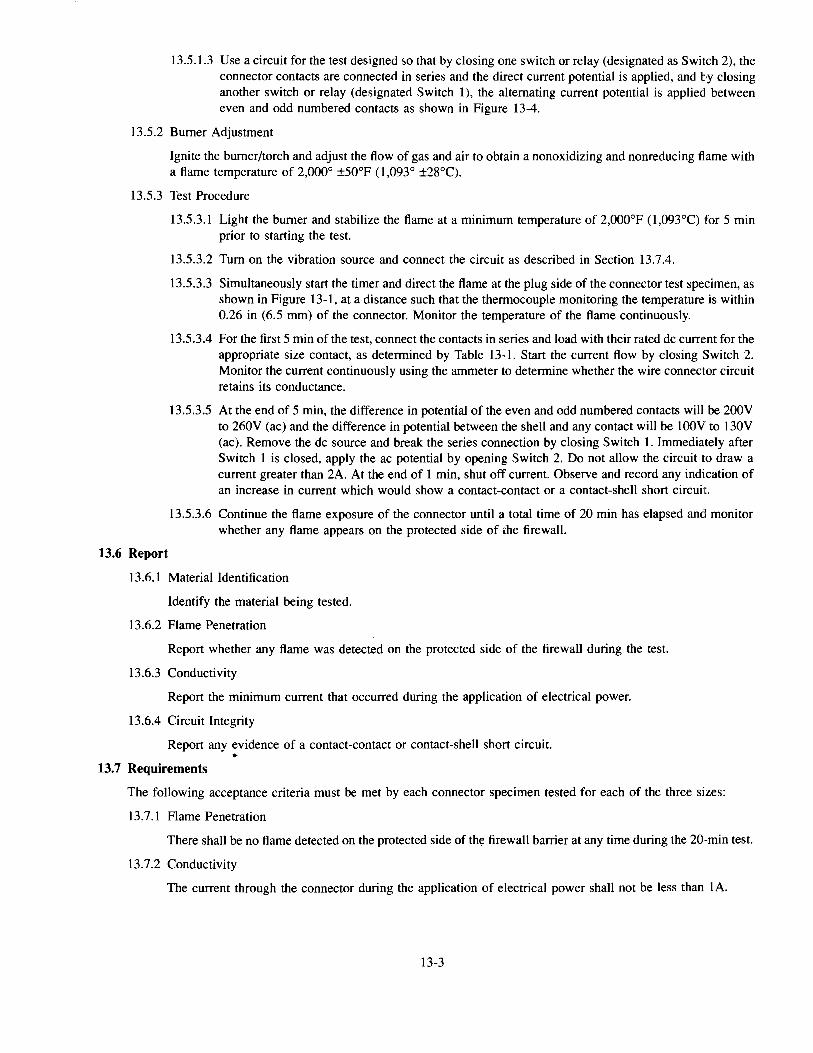
13.5.1.3 Use a circuit for the test designed so that by closing one switch or relay (designated as Switch 2), the connector contacts are connected in series and the direct current potential is applied, and by closing another switch or relay (designated Switch 1), the alternating current potential is applied between even and odd numbered contacts as shown in Figure 13-4.
13.5.2 Burner Adjustment
Ignite the burner/torch and adjust the flow of gas and air to obtain a nonoxidizing and nonreducing flame with a flame temperature of 2,000° ±50°F (1,093° ±28°C).
13.5.3 Test Procedure
13.5.3.1 Light the burner and stabilize the flame at a minimum temperature of 2,000°F (1,093°C) for 5 min prior to starting the test.
13.5.3.2 Tum on the vibration source and connect the circuit as described in Section 13.7.4.
13.5.3.3 Simultaneously start the timer and direct the flame at the plug side of the connector test specimen, as shown in Figure 13-1, at a distance such that the thermocouple monitoring the temperature is within 0.26 in (6.5 mm) of the connector. Monitor the temperature of the flame continuously.
13.5.3.4 For the first 5 min ofthe test, connect the contacts in series and load with their rated de current for the appropriate size contact, as determined by Table 13-1. Start the current flow by closing Switch 2. Monitor the current continuously using the ammeter to determine whether the wire connector circuit retains its conductance.
13.5.3.5 At the end of 5 min, the difference in potential of the even and odd numbered contacts will be 200V to 260V (ac) and the difference in potential between the shell and any contact will be lOOV to 130V (ac). Remove the de source and break the series connection by closing Switch 1. Immediately after Switch 1 is closed, apply the ac potential by opening Switch 2. Do not allow the circuit to draw a current greater than 2A. At the end of 1 min, shut off current. Observe and record any indication of an increase in current which would show a contact-contact or a contact-shell short circui1t.
13.5.3.6 Continue the flame exposure of the connector until a total time of 20 min has elapsed and monitor whether any flame appears on the protected side of the firewall.
13.6 Report
13.6.1 Material Identification
Identify the material being tested.
13.6.2 Flame Penetration
Report whether any flame was detected on the protected side of the firewall during the test.
13.6.3 Conductivity
Report the minimum current that occurred during the application of electrical power.
13.6.4 Circuit Integrity
Report any evidence of a contact-contact or contact-shell short circuit. •
13.7 Requirements
The following acceptance criteria must be met by each connector specimen tested for each of the three sizes:
13.7.1 Flame Penetration
There shall be no flame detected on the protected side of th~ firewall barrier at any time during the 20-min test.
13.7.2 Conductivity
The current through the connector during the application of electrical power shall not be less than lA.
13-3
13.7.3 Circuit Integrity
There shall be no evidence of any contact-contact or contact-shell short circuit.
13.7.4 Backside Ignition
There shall be no ignition on the back side of the wire bundle.
13-4
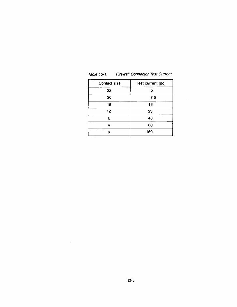
Table 13-1. Firewall Connector Test Current
Contact size Test current (de)
22 5
20 7.5
16 13
12 23
8 46
4 80
0 150
13-5
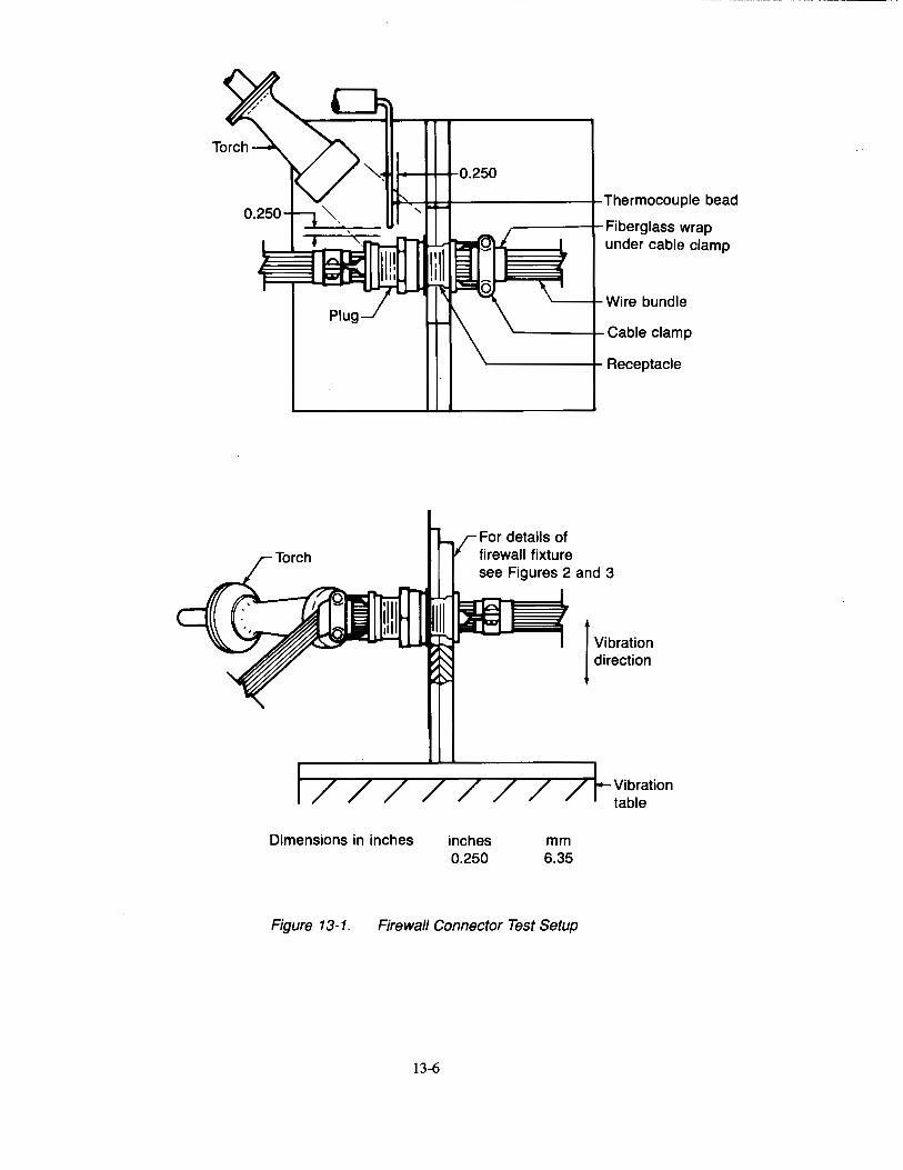
~......-~,..r-,t---------+-Thermocouple bead
Dimensions in inches
,----r Fiberglass wrap under cabh~ clamp
~-t-Wire bundle
~---.._Cable clamp
'-------+ Receptacle!
For details of firewall fixture see Figures 2 and 3
inches 0.250
mm 6.35
I Vibration direction
Vibration table
Figure 13-1. Firewall Connector Test Setup
13-6
Connector mounting plate (0.0625 thick)
Detail A
0 0
0 0
0 0
0
10~00_j
Dimensions in inches
0.250 Sheet ceramic or equivalent
Support plate
7. 00
l
inches 0.125 0.190 0.250 0.500 1.000 1.250 7.000 8.200
10.000 11.000
See detail B
See detail A
1.000
mild steel
0.190 0 32NC X 1-0.280 socket HD cap screw (17 req)
Detail B
mm 3.18 4.83 6.35
12.70 25.40 31.75
177.80 208.28 254.00 279.40
Figure 13-2. Firewall Connector Fixture Assembly
13-7
0.250 sheet ceramic
0.208 dia 0.202
0
0.208 dia 0.202 (12 req'd) (see hole pattern)
0.336 dia 0.329 (2 req'd)
mild steel
10.000---j
T 0 0 10.000
~OJ_ 0.500
(17 req'd) (see hole pattern)
(see note 2) 13 (4 req'd) (see note 3)
Sheet Ceramic
0.209 d' 0.202 Ia (typ) (ref)
Connector Mounting Plate
1.000 ..jf+-0.500
11 +1 r-o.5oo 0 0
-2.!oo 0 '--44+--' 0 0 ·--+1--
(ref) 2.j00 t
l__ : 0 0 0
: =_!_ 1.500
0.208 dia 0.202 (17 req'd) (See hole Support Plate pattern)
Notes: 1. Dimensions are in inches. Unless otherwise specified,
dimensions symmetrical about centerline. 2. A hole shall provide suitable clearance for the
applicable connector. 3. B connector mounting holes shall be as specified
on the applicable MS standard.
I I I • • t---10.00 (ref)-J 0.500
ct. Hole Pattern
inches mm 0.125 3.18 0.190 4.83 0.250 6.35 0.500 112.70 1.000 ~~5.40
1.250 ~11.75 7.000 1'l7.80 8.200 208.28
10.000 2S4.00 11.000 2i'9.40
Figure 13-3. Firewall Connector Fixture Details
13-8
Switch 1 ,-------~~~--~:~~nconta~~~------------~
I I
Figure 13-4. Connector Electrical Integrity Connection Diagram
13-9
Load 28V (de)

This page intentionally left blank
13-10
Chapter 14 Test for Electrical Wire Used in Designated Fire Zones
14.1 Scope
14.1.1 This test method is intended for use in determining the resistance of high-temperature electrical wire used in designated fire zones to damage due to flame and vibration according to the requirements of FAR 25.863, FAR 25.865, FAR 25.867, FAR 25.1201, FAR 25.1203, and FAR 25.1359.
14.1.2 This test method generally follows MIL-W-25038E. The method is used predominantly in the United States and by most of the wire and cable manufacturers. ISO/DIS 2685.2 is a similar test procedure, and is used by Aerospatiale in France, and by the Civil Aviation Authority (CAA) in Great Britain.
14.2 Definitions
14.2.1 Ignition Time
The length of time the burner flame is applied to the specimen. In this test, the ignition time is 5 min.
14.2.2 Wire
A single insulated electrical conductor.
14.2.3 Designated Fire Zone
A region of the aircraft such as engine and auxiliary power unit compartments designated to require fire detection and extinguishing equipment, and as appropriate the use of materials that are fire resistant or fire proof.
14.2.4 Fire Resistant
Per FAR Part 1, "with respect to fluid carrying lines, fluid system parts, wiring, air ducts, fittings, and powerplant controls means the capacity to perform the intended functions under the heat and other conditions likely to occur when there is a fire at the place concerned."
Electrical wire is demonstrated to be fire resistant by meeting the requirements of this 5-minute test.
14.2.5 Firewall
A structure designed to prevent a hazardous quantity of air, fluid, or flame from exiting a designated fire zone in which a fire has erupted, and causing additional hazard to the aircraft.
14.2.6 Fire Zone Wire
A wire installed in a designated fire zone.
14.3 Apparatus
14.3.1 Test Fixture
A test fixture such as shown in Figure 14-1 shall be provided. The fixture shall include a provision for mounting above the test burner.
14.3.2 Test Burner
A test burner such as shown in Figure 14-2 shall be provided. 1 The burner shall include provisions for introducing air pre-mixed with the gas fuel, and for introducing secondary air into the burner flamelets.
14.3.2.1 Burner Fuel
Propane gas of 99% minimum purity shall be used for the burner fuel.
14.3.2.2 Plumbing for Gas Supply
The necessary gas connections, tubing, pressure regulators, and gauges shall be provided.
1See SAE AS-8028 for burner details.
14-1
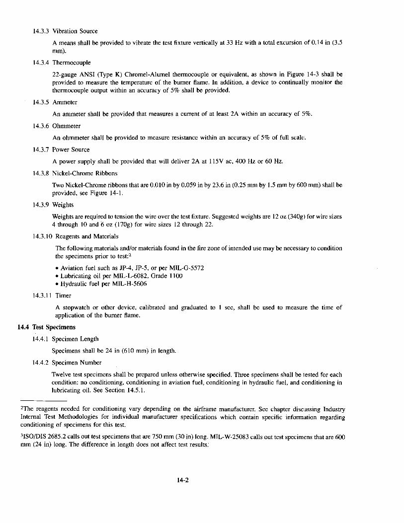
14.3.3 Vibration Source
A means shall be provided to vibrate the test fixture vertically at 33 Hz with a total excursion of 0.14 in (3.5 mm).
14.3.4 Thermocouple
22-gauge ANSI (Type K) Chromel-Alumel thermocouple or equivalent, as shown in Figure 14-3 shall be provided to measure the temperature of the burner flame. In addition, a device to continually monitor the thermocouple output within an accuracy of 5% shall be provided.
14.3.5 Ammeter
An ammeter shall be provided that measures a current of at least 2A within an accuracy of 5%.
14.3.6 Ohmmeter
An ohmmeter shall be provided to measure resistance within an accuracy of 5% of full scak.
14.3.7 Power Source
A power supply shall be provided that will deliver 2A at 115V ac, 400Hz or 60 Hz.
14.3.8 Nickel-Chrome Ribbons
Two Nickel-Chrome ribbons that are 0.010 in by 0.059 in by 23.6 in (0.25 mm by 1.5 mm by 600 mm) shall be provided, see Figure 14-1.
14.3.9 Weights
Weights are required to tension the wire over the test fixture. Suggested weights are 12 oz (340g) for wire sizes 4 through 10 and 6 oz ( 170g) for wire sizes 12 through 22.
14.3.10 Reagents and Materials
The following materials and/or materials found in the fire zone of intended use may be necessary to condition the specimens prior to test:2
• Aviation fuel such as JP-4, JP-5, or per MIL-G-5572 • Lubricating oil per MIL-L-6082, Grade 1100 • Hydraulic fuel per MIL-H-5606
14.3.11 Timer
A stopwatch or other device, calibrated and graduated to 1 sec, shall be used to measure the time of application of the burner flame.
14.4 Test Specimens
14.4.1 Specimen Length
Specimens shall be 24 in (610 mm) in length.
14.4.2 Specimen Number
Twelve test specimens shall be prepared unless otherwise specified. Three specimens shall be tested for each condition: no conditioning, conditioning in aviation fuel, conditioning in hydraulic fuel, and conditioning in lubricating oil. See Section 14.5.1.
2The reagents needed for conditioning vary depending on the airframe manufacturer. See chapter discussing Industry Internal Test Methodologies for individual manufacturer specifications which contain specific information regarding conditioning of specimens for this test.
3ISO/DIS 2685.2 calls out test specimens that are 750 mm (30 in) long. MIL-W-25083 calls out test specimens that are 600 mm (24 in) long. The difference in length does not affect test results.
14-2

14.5 Conditioning/Preparation of Test Specimens
14.5.1 Test Conditions
Each wire type shall be tested without being exposed to any contaminating fluid, and after being exposed to each of the fluids described in Section 14.3.10. Three test specimens4 shall be used for each of the test conditions.
14.5.1.1 Immerse three test specimens in each test fluid for the times and temperatures shown in Table 14-1. Wipe the test specimens with a clean cloth after removing them from the fluids.
14.5.1.2 Locate the point on the wire specimen that will be located directly above the center o:f the burner when the wire specimen is placed on the test stand. Mark a 7-in (178-mm) long section with this point in its center by placing a wire band5 around the specimen 3-Yz in (89 mm) on each side of this point. In addition place a outer wire band around the test specimen 4 in (102 mm) outside each of these two bands.
14.5.2 Store each set of test specimens in a separate airtight container until the time of test.
14.6 Calibration
14.6.1 Position the thermocouple as shown in Figure 14-3, I in (25 mm) above the center of the burner top plate as is shown in Figure 14-4.
14.6.2 Ignite the burner and adjust the fuel, air, and secondary air to the burner to obtain a nonoxidizing, nonreducing flame with no yellow tips at a temperature of 2,000° ±50°F (1,093° ±28°C). Stabilize the flame for 5 min.
14.6.3 Tum off the burner after the flame is properly adjusted.
14.7 Procedure
14.7.1 Test Setup
Position the test specimen I in (25 mm) above the burner top plate. Place the center 7 in ( 178 mm) section of the specimen above the center of the burner. See Figure 14-4.
14.7.1.1 Position the two nickel-chrome ribbons at a distance of 1 in (25 mm) apart as measured at the center 7 -in ( 178-mm) section of the ribbons and perpendicular to the test specimen. Clamp one ,;:nd of each of the nickel-chrome ribbons to the test fixture. Wrap the nickel-chrome ribbons around the wire and tension with weights. Lock the wires at the pulley or clamp them it to the test fixture. See JFigure 14-4 for details.
14.7.1.2 Connect the conductor and the nickel-chrome ribbons as shown in Figure 14-5.
14.7.1.3 Insert a shorting bar between the conductor and the nickel-chrome ribbons. Adjust the ohmmeter to zero in this position.
14.7.1.4 Start the vibration using a frequency of 33Hz and a vertical amplitude of 0.14 in (3.5 mm).
14.7.2 Test Procedure
14.7.2.1 Start the vibration using a frequency of 33Hz and a vertical amplitude of 0.14 in (3.5 mm).
14.7.2.2 Simultaneously start the timer and apply the ignited burner to the specimen.
14.7.2.3 Monitor the flame temperature for the duration of the test. Adjust the secondary air continually as necessary to keep the flame and the temperature within the limits specified in Section ll4.6.3.
4All current industry specifications require only one specimen for each fluid. However, testing three specimens for each fluid will provide greater degree of confidence in the results.
5The wire band consists of one tum of A WG 30 or smaller wire.
14-3
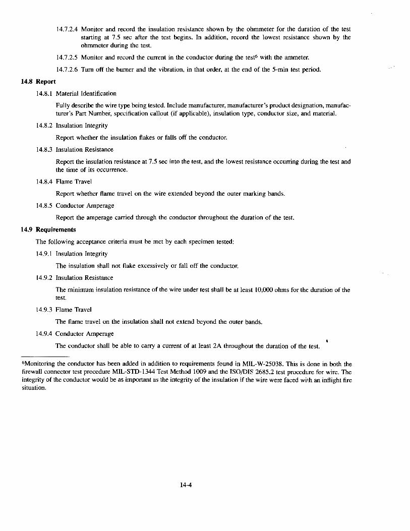
14.7.2.4 Monitor and record the insulation resistance shown by the ohmmeter for the duration of the test starting at 7.5 sec after the test begins. In addition, record the lowest resistance shown by the ohmmeter during the test.
14.7.2.5 Monitor and record the current in the conductor during the test6 with the ammeter.
14.7.2.6 Tum off the burner and the vibration, in that order, at the end of the 5-min test pe:riod.
14.8 Report
14.8.1 Material Identification
Fully describe the wire type being tested. Include manufacturer, manufacturer's product designation, manufacturer's Part Number, specification callout (if applicable), insulation type, conductor size, and material.
14.8.2 Insulation Integrity
Report whether the insulation flakes or falls off the conductor.
14.8.3 Insulation Resistance
Report the insulation resistance at 7.5 sec into the test, and the lowest resistance occurring dming the test and the time of its occurrence.
14.8.4 Flame Travel
Report whether flame travel on the wire extended beyond the outer marking bands.
14.8.5 Conductor Amperage
Report the amperage carried through the conductor throughout the duration of the test.
14.9 Requirements
The following acceptance criteria must be met by each specimen tested:
14.9.1 Insulation Integrity
The insulation shall not flake excessively or fall off the conductor.
14.9.2 Insulation Resistance
The minimum insulation resistance of the wire under test shall be at least I 0,000 ohms for the duration of the test.
14.9.3 Flame Travel
The flame travel on the insulation shall not extend beyond the outer bands.
14.9.4 Conductor Amperage
The conductor shall be able to carry a current of at least 2A throughout the duration of the test.
6Monitoring the conductor has been added in addition to requirements found in MIL-W-25038. This is done in both the firewall connector test procedure MIL-STD-1344 Test Method 1009 and the ISO/DIS 2685.2 test procedure for wire. The integrity of the conductor would be as important as the integrity of the insulation if the wire were faced with an inflight fire situation.
14-4
Table 14-1. Specimen Immersion Information
Immersion Specimen
Test fluid No.
Time (hr) Temp (C)
MIL-G-5572 (grade 100/130) 24 2~1
1 JP-5 24 2a
JP-4 24 23
2 50% JP-4 and 24 2~1 50% MIL-L-6082
3 MIL-L-6082 24 121
4 Skydrol 500841L04 (aero) 24 2~1
5 Ethylene Glycol (aero) 24 121
14-5
Tensioning spring
Nickel-chrome ribbons
Test specimen
Weights used for Wire sizes 22 through 12: 170g Wire sizes 1 0 through 4: 340g
Figure 14-1. Firezone Electrical Wire Test Setup
14-6
Tensioning spring
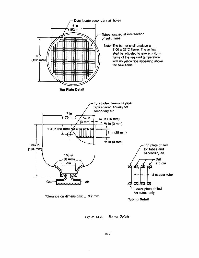
6 in (152 mm)
Dots locate secondary air holes
6in /_ (152 mm)
~ ~v-Tubes located at intersection ~ .. : : : : : : : : . . of solid lines
1 . : : : : : : : : : : : : : : : : . l\ Note: The burner shall produce a 1· : : : : : : : .: : : : : : : : : : : . ~ 1100 ± 25°C flame. The airflow
. . . . . . . . . . . . . . . . . . . . shall be adjusted to give a uniform : : : : : : : : : : : : : : : : : : : : flame of the required temperature : : : : : : : : : : : : : : : : : : : : with no yellow tips appearing above
Top Plate Detail
the blue flame.
Four holes 3-mm-dia pipe taps spaced equally for secondary air
Top plate drilled for tubes and
,-----.----,~ Dri II 2.5 dia
Tolerance on dimensions: ± 0.2 mm Tubing Detail
Figure 14-2. Burner Details
14-7
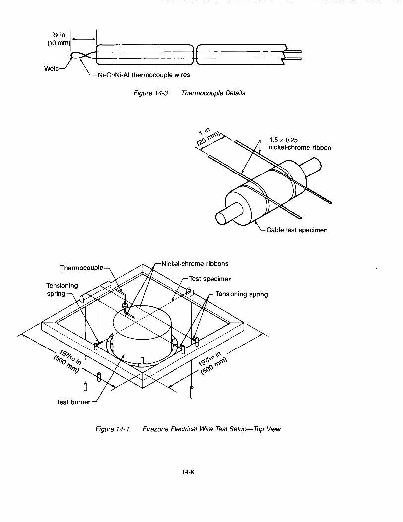
Thermocouple
Figure 14-4.
Figure 14-3. Thermocouple Details
Nickel-chrome ribbons
1.5 X 0.25 nickel-chrome ribbon
Cable test specimen
Firezone Electrical Wire Test Setup-Top View
14-8
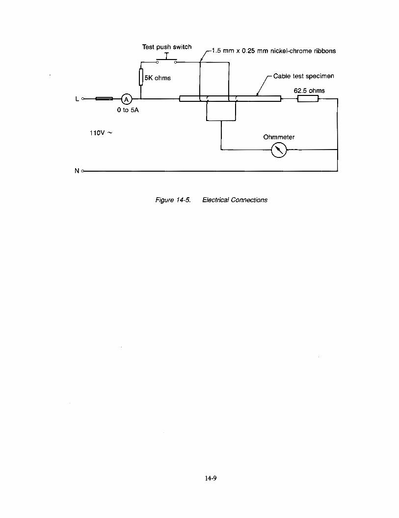
1.5 mm x 0.25 mm nickel-chrome ribbons
Cable test specimen
0 to SA
110V'"" Ohmmeter
N~--------------------------------~
Figure 14-5. Electrical Connections
14-9

This page intentionally left blank
14-10
APPENDIX A FAA Regulations
A.l A Brief History of Federal Agencies Regulating Aviation
The Federal Aviation Administration has had its present name and place in the Federal establishment since April 1, 1967, the day the Department of Transportation began operations. It has existed, however, in recognizably similar forms since 1926, when Congress enacted the Air Commerce Act establishing an Aeronautics Branch within the Department of Commerce. Passed at the request of the aviation industry, which believed the airplane could not reach its full commercial potential without Federal safety regulation, the act charged the Secretary of Commerce with fostering air commerce, issuing and enforcing air traffic rules, licensing pilots, certificating aircraft, establishing airways, and operating and maintaining aids to air navigation.
Over the next decade, the Department of Commerce fulfilled its civil aviation responsibilities by concentrating on airway development, safety rulemaking, and pilot and aircraft certification. In 1936, a major shift occurred: Commerce assumed responsibility for controlling en route air traffic. Air Traffic Control (ATC) eventually became, in terms of manpower and facilities employed, the Federal Government's most demanding civil aviation responsibility.
In 1938, with the enactment of the Civil Aeronautics Act, the Federal civil aviation role passed from Commerce to a new independent agency, the Civil Aeronautics Authority. That legislation expanded the Federal civil aviation role by giving the Authority the power to issue air carrier route certificates and regulate airline fares. In 1940, President Franklin Roosevelt split the Authority into two agencies, the Civil Aeronautics Board (CAB) and the Civil Aeronautics Administration (CAA). The CAA, lodged in the Department of Commerce, was responsible for ATC, airman and aircraft certification, safety enforcement, and airways development. In 1946, Congress added to these responsibilities a Federal aid airport program.
The Federal Aviation Act of 1958, whose passage had been spurred by a series of midair collisions, transferred the CAA's functions to a new independent body, the Federal Aviation Agency (FAA). This act was significant in two other respects. It took safety rulemaking from the CAB and entrusted it to the FAA. More importantly, it gave the FAA the sole responsibility for developing and maintaining a common civil-military system of air navigation and air traffic control, a responsibility which the CAA had shared with others.
In 1967, the FAA was renamed the Federal Aviation Administration and placed in the newly created Department of Transportation. The creation of the DOT reflected a growing awareness in the Congress, the executive branch, and the transportation industry that integrated and balanced transportation systems were required to meet the nation's transportation needs and that such systems could best be achieved by a single department.
Meanwhile, the FAA was assuming responsibilities not originally contemplated by the Federal Aviation Act. In 1968, Congress vested in the FAA Administrator the power to prescribe aircraft noise standards. The hijacking epidemic of the 1960s also involved the agency in a new area, aviation security. Finally, in 1970, the Airport and Airway Development Act authorized the FAA Administrator to establish minimum safety standards for airports and issue operating certificates to air carrier airports meeting those standards.
In the 1970s, the FAA and other Federal employees joined the ranks of organized labor. The Federal union movement began in 1962, when President John F. Kennedy granted by executive order the right of Federal employees to join unions and engage in collective bargaining. In 1968, a group of New York-based controllers formed the Professional Air Traffic Controllers Organization (PATCO), a professional society that eventually became a labor union. FAAPATCO relations fell into three distinct periods: the early, strife-marked period that cufminated in a 1970 "sickout" in which 3,000 controllers participated; a period of relative labor peace that saw controllers gain valuable wage and retirement benefits; and another period of strife, beginning in 1980, that led to 12,300 PATCO members goilng on strike in August 1981, the firing of the strikers, and the decertification of PATCO. Despite the loss of most of its controller workforce, FAA kept the airways open and brought the ATC system close to its 1981 capacity within two years.
Airspace system capacity, however, was a long-term problem. Congress had created the FAA to meet the airspace challenges of the jet age. A large part of the FAA's response was the third-generation ATC system, a semiautomated radar- and computer-based system. That system was capitalized by user taxes from a trust fund created by the Airport and Airway Revenue Act of 1970. Despite the steady infusion of trust fund capital, the third-generation ATC system showed signs of wear by the early 1980s. Air traffic had surged dramatically, testing the limits of the system's capacity.
A-1

Traffic growth had been fed in part by the competitive environment created by the Airline Deregulation Act of 1978, which introduced fare and route competition in the air passenger industry and permitted unrestricted entry by new domestic carriers. Accordingly, in December 1981, FAA unveiled the National Airspace System Plan, a blueprint for a state-of-the-art traffic control and air navigation system to accommodate projected growth in air travel! over the next 20 years.
A.2 Organization of the FAA
The Federal Aviation Administration is currently part of the Department of Transportation and is under the leadership of an Administrator who reports to the Secretary of Transportation.
The organizational structure of the FAA has undergone numerous changes over the years. Regardless of changes at the top levels of FAA headquarters and field offices, the "firing line" levels at or near the bottom, where the ultimate action takes place, have usually been relatively unaffected. Future reorganizations most likely will have little, if any, effect on day-to-day work functions of the local FAA offices. This familiarization with the FAA organization will, therefore, be based upon that assumption.
A.2.1 Headquarters
The top levels at FAA headquarters for design certification, production certification, and airworthiness certification begin with the Executive Director for Regulatory Standards and Compliance, under whom is the Associate Administrator for Regulation and Certification. Among the offices under the Associate Administrator is the Aircraft Certification Service, which has the responsibility for overseeing the Aircraft Certification Directorates, and the Washington Headquarters operations related to design, production, and airworthiness certification. The Aircraft Manufacturing Division of the Aircraft Certification Service has total responsibility for national policy and regulations governing production of aircraft and replacement parts (quality assurance), and the requirements for issuance of airworthiness certificates and export approvals. The engineering functions for aircraft and engine design certification policy and regulations are divided among four field offices, called Directorates. The Aircraft Engineering Division of the Aircraft Certification Service is responsible for national policy that affects all four of the Directorates, and for policy and regulations for unique aircraft not otherwise covered by an aircraft category.
A.2.2 Directorates/Aircraft Certification Division
The headquarters of the Aircraft Certification Directorates/Divisions (ACD) and the categori~:s for which they are responsible are as follows:
A. For Transport Category Airplanes (FAR Part 25), the Directorate headquarters is in Seaule, Washington.
B. For small airplanes (FAR Part 23), the Directorate headquarters is in Kansas City, Missouri.
C. For rotorcraft of all categories (FAR Parts 27 and 29), the Directorate headquarters is in Fort Worth, Texas.
D. For engines and propellers (FAR Parts 33 and 35), the Directorate headquarters is in Boston, Massachusetts.
The ACD is also responsible for implementing the certification programs (Type, Production, and Airworthiness) within the geographic boundaries of the Directorate, subject to the policy guidance of the ACD in the Directorate responsible for the product involved. For example, the transport category Directorate is responsible for accomplishing all of the work required for type certification of an engine whose manufacture is located in Seattle, but the engine/propeller Directorate headquartered in Boston is responsible for policy guidance and regulatory interpretations, if required.
Each Directorate/Division is responsible for development, coordination, and issuance of documents related to the assigned category, including-
A. Airworthiness directives
B. Regulatory changes
C. New regulations
D. Advisory circulars
E. FAA internal directives (orders, notices, etc.)
A-2
Note: The authority outlined above does not include changes to procedural regulations, such as FAR Part 21, that would affect all Directorates. Such changes are the responsibility of the Engineering Division in FAA Washington Headquarters.
A.2.3 Directorates/Aircraft Certification Offices
The day-to-day work functions within the geographic area for which each Directorate is responsible are carried out by Aircraft Certification Offices (ACO) whose managers report to the Directorate Aircraft Certification Division. The ACOs consist of Branches and Sections covering the various engineering specialties related to design certification of aircraft, aircraft engines, propellers, and replacement parts for those products. The ACO design certification programs encompass all categories of products whose manufacturers are located within the ACO geographic area of responsibility. Policy guidance for ACO design approval projects is provided by the Directorate responsible for the particular category of product. Each ACO may also include a Manufacturing Inspection Branch, responsible for monitoring the manufacturing (quality assurance) and airworthiness certification programs, with policy guidance from the Manufacturing Division at FAA headquarters.
A.2.4 Directorates/Manufacturing Inspection District Offices
The managers of the Manufacturing Inspection District Offices (MIDO) report to the manager of the ACO, except that for technical policy guidance, reporting may be to the Aircraft Certification Division, at the option of the ACO manager. The MIDO's primary functions are not related to any specific product category, as in Engineering, since such functions are generally similar regardless of the type of product involved. The MIDO responsibilities include-
A. Evaluation of production quality assurance systems for compliance with the FAR, leading to issuance of production approvals.
B. Surveillance of approved production facilities.
C. Providing support to FAA Engineering in design approval programs, through conformity inspections of prototype/first article products, and witnessing tests as requested by Engineering.
D. Issuance of airworthiness certificates for new aircraft.
E. Issuance of export approvals for new aircraft, aircraft engines, propellers, or their major components.
F. Enforcement of the FAR applicable to production approvals.
The MIDO manager may assign Principal Inspectors (Pis) for major production approval holders. The PI is responsible for oversight of his assigned manufacturer, and for assuring the timely accomplishment of the MIDO functions that apply.
A.2.5 FAA Technical Center (FAATC)
The FAA Technical Center (FAATC) is located at the Atlantic City International Airport. It serves as the national test center for FAA research and development programs in air traffic control, communications, navigation, airports, and aircraft safety. Work involves long-range development of new systems and concepts, development of new equipment and techniques to be placed in service in the near future, and inservice modifications of existing systems and procedures.
Most of the ongoing technical projects are assigned by FAA headquarters. Some testing takes place at other locations where the environment is more suitable. Some work is contracted to private industry and universities.
Center test pilots operate a fleet of specially instrumented aircraft that range in size from small airplanes to helicopters and large transports.
Major test facilities include-Air Traffic Simulation Facility Air Traffic Laboratories Radar Test Laboratories Navigation Facilities Tracking Range Aircraft Safety Area
A-3
The Aircraft Safety Area contains special facilities for fire and accident tests on aircraft, components, and engines. They include a catapult, wind tunnel, chemistry laboratory, engine test cells, and a full-scale fire test facility, the largest of its kind in the world.
A.2.6 Civil Aeromedical Center (CAMI)
The Civil Aeromedical Institute (CAMI) is located at the Mike Monroney Aeronautical Center at the Oklahoma City Airport. It conducts medical research projects applicable to the mission of the FAA; develops, maintains, and manages a system for the medical examination and certification of U.S. civil airmen; and develops, maintains, and administers aviation medical education programs to meet the needs of the FAA. It also participates in the investigation of aircraft accidents regarding survivability factors and biomedical and psychological causes of accidents such as disease and substance abuse.
A.3 Enabling Legislation and Procedures for The FAA
The top level public law that governs the activities of the FAA is The Federal Aviation Act of 1958, as amended. All of the FAA operating procedures must be in accordance with the Federal Aviation Act. Conversely, the FAA cannot enforce regulations or procedures that are in conflict with the provisions of the Federal Aviation Act. The Act may be amended by Congress, however, if a compelling need for such amendment exists.
Most of the FAA operations are covered under Title VI "Safety Regulation of Civil Aeronautics." Section 60 I of this Title gives the FAA administrator the "power" and the "duty" to prescribe and revise "minimum standards" and "rules and regulations" governing, among other things, "the design, material, workmanship, con:;truction, and performance of aircraft, aircraft engines, and propellers as may be required in the interest of safety." Therein lies the basis for the Federal Aviation Regulations.
A.3.1 Federal Aviation Regulations (FARs)
FARs are issued by the FAA to implement the provisions of the Federal Aviation Act, which gives only the basic objectives with little detail. Compliance with the FARs is mandatory to obtain the kind of certificates or approvals to which the particular FAR applies. Once a certificate or approval is issued for a purpose that requires ongoing compliance, such as a Production Certificate, noncompliance with, or violation of the terms of, the approval would result in civil penalty or administrative enforcement action, or, if the infraction is of serious nature, the certificate or approval could be suspended or revoked.
A.3.l.l Development of FARs
Anyone may propose new FARs or amendments to existing FARs. The FAA may initiate the action, or private individuals or organizations, such as the Aerospace Industries Association (AlA), Air Transport Association (ATA), etc., may submit a Petition for Rulemaking to the FAA for rulemaking action.
After the FAA adopts a new regulation, it is published in the FEDERAL REGISTER and in the Code of Federal Regulations, available for purchase by the public; however, these documents are reference only from a legal standpoint.
A.3.1.1.1 Petitions for Rulemaking
The procedures to be followed in presenting Petitions for Rulemaking are deltailed in FAR Part 11. The basic requirements that must be met in a petition are that the petition must explain the interests of the petitioner in the action sought, and contain information, views, or arguments as to why granting the request would be in the public interest.
If the FAA determines that the basic requirements for a petition have been met, a summary of the petition is published in the FEDERAL REGISTER and public comments are invited. To be considered, comments must be submitted to the FAA within a time period specified in the published summary (usually 60 days). If the FAA finds that the petition is not acceptable after considering the public comments, it is returned to the petitioner, who may then resubmit the petition with additional information. If, however, the FAA determines, after consideration of its own analysis of the petition and of all public comments received in response to the summary that the petition has merit, the FAA institute~; rulemaking procedures.
A-4
A.3.1.1.2 Notices of Proposed Rulemak:ing (NPRMs)
When the FAA initiates rulemak:ing, a part of the rulemak:ing action is publication of the proposed new or amended regulation in the FEDERAL REGISTER as a Notice of Proposed Rulemak:ing (NPRM), with public comments invited. To be considered, comments must be submitted to the FAA within a time period specified in the published NPRM. Each c:omment received must be analyzed by the FAA and may be either accepted or rejected, depending on whether the commenter has provided justification and substantiation of his/her views. Comments that state simply "for" or "against" without support information are generally not given consideration. The substance of comments that are accepted would be incorporated into the proposed regulation.
After all actions related to the NPRM and comments received are completed, and the proposed rule has completed the interagency coordination process, the final rule may be approved by the FAA Administrator or his designee.
Because of the extensive coordination required for rulemak:ing actions, including the Department of Transportation and the Office of Management and Budget, the time elapsed between initiation of the action and adoption of the final rule may be a year or more, depending on whether the proposed rule is imposing or relieving a burden on the public, and whether the proposal is controversial in nature. The only exception to the long time element is in the case of Airworthiness directives, which may be processed quickly under emergency procedures.
A.3.1.2 Exemptions from FARS
Anyone may petition the FAA for an exemption from a regulation{s) following the procedures set forth in FAR Part 11, which are similar to those for petition for rulemak:ing. The primary difference between a petition for exemption and a petition for rulemak:ing is that the petitioner for an exemption must include reasons why safety would not be adversely affected if the exemption is granted, or, must explain the action to be taken by the petitioner to provide a level of safety equal to that provided by the rule from which the exemption is sought.
The processing of a petition for exemption is also similar to that for a petition for rulemak:ing, except that full interagency coordination is generally not necessary or is accomplished more quickly. The final action on a petition for exemption may usually be determined within 60 to 90 days, or if the petitioner shows good cause, may be completed sooner.
The final action on a petition for an exemption may be either a grant if the petitioner has shown good cause, or a denial if he/she has not. In the case of a denial, the petition may be resubmitt,ed if the petitioner has new information that would provide better substantiation.
The scope of exemptions varies considerably-an exemption may be valid only for one person on a short-term basis, or may apply to an organization or group and be effective for several years. Exemptions are not normally granted on a permanent basis, but in cases where the need is ongoing for many years, the original petitioner may request renewal when the exemption expires, provided the need for the renewal is adequately substantiated.
An exception to the usual requirement that exemptions expire on a given date unless renewed is the case of an exemption granted from a regulation(s) in the airworthiness standards of FAR Parts 23 or 25. Such exemptions may be permanent, and since they constitute a deviation from the published airworthiness standards, they must be listed on the Standard Airworthiness Certificates issued for the aircraft affected by the exemption, to satisfy the requirements of the International Civil Aviation Organization (ICAO).
A.3.2 Airworthiness Directives (ADs)
ADs are issued by the FAA when an unsafe condition exists in a product, and that condition is likely to exist in other products of the same type design. The need for an AD may ,be identified as a result of an accident, maintenance problems, routine inspections, etc. The primary criteria upon which the FAA bases decisions for AD action are that an unsafe condition was found, and that the same condition is likely to exist in other aircraft.
A-5
The corrective action prescribed by the AD, such as an inspection, repair, or modification, may be detailed in the AD itself or may be contained in another document, such as a manufacturer's Service Bulletin, which is referenced in the AD.
ADs have the same authority as a Federal Aviation Regulation, and as such, compliance with ADs is mandatory. Noncompliance with an AD that, for example, applies to an aircraft would be violation of the terms of issuance of the airworthiness certificate resulting in its invalidation-in effect, grounding the aircraft. The same effect would result if an engine, propeller, or applicance with an unincorporated AD is installed on an aircraft.
The procedures for processing ADs generally follow those previously discussed under development of FARs, beginning with publication of the draft AD in the FEDERAL REGISTER as an NPRM, with public comments invited, except that, when the situation requires urgent action to preserve safety, an emergency AD may be issued immediately without the full rulemaking process.
The FAA Directorate for the product involved, usually in conjunction with the local ACO, is responsible for drafting the AD and coordinating the rulemaking process. The text of the AD and the correctilve action is usually a joint effort between the manufacturer and FAA engineering. Input and comments are also considered from other segments of the FAA and from individuals or organizations representing the aircraft operators.
A.3.3 Technical Standard Orders (TSOs)
Under the Civil Aeronautics Act of 1938 the Administrator of Civil Aeronautics was authorized to adopt the Technical Standard Order (TSO) system is to establish minimum performance standards and specifications of aircraft materials, parts, processes, and appliances which are used on civil aircraft.
TSOs are covered in FAR Part 21-"Certification Procedures for Products and Parts"-as Subpart 0-"Technical Standard Order Authorizations." The TSO requirements cover most, but not necessarily all, of the requirements on that item in the FARs.
A TSO Authorization is an FAA design and production approval issued to the manufacturer of an article which has been found to meet a specific TSO.
A Letter of TSO Design Approval is an FAA design approval for a foreign-manufactured article, which has been found to meet a specific TSO in accordance with specified procedures.
A.3.4 Congressional Actions
In a number of cases involving controversial issues, Congress has passed amendments to the Act which mandate FAA action, even though the Act may already provide for such action. Notable examples of this are all sections in Title VI, amended to require Emergency Locator Transmitters in certain aircraft, to establish Noise Abatement requirements, and, most recently, to establish requirements for Mode C transponders in aircraft operating in controlled airspace.
A.3.5 Directives That Implement FARs
Directives that implement FARs are issued to provide guidance or an acceptable means of compliance with specific FARs. Such directives are not normally mandatory on an applicant for an FAA certificate or approval. If compliance with their provisions would result in a burden on, or adversely affect a segment of the aviation community, a draft must be published in the FEDERAL REGISTER for public review and comment, which must be considered before the directive can be issued. This requirement in fact applies to all directives issued by any U.S. Government agency, including those whose purpose is to govern internal operations, but in so doing may have an adverse effect on the public.
A.3.5.1 Advisory Circulars (ACs)
The FAA issues ACs to inform the aviation public in a systematic way of nonregulatory material of interest. Unless incorporated into a regulation by reference, the contents of an AC are not binding on the public. Among other things, ACs are used to show a method acceptable to the FAA, but which may not be the only method, for complying with a related FAR.
A-6
ACs are available to the public through several means. Some are free, depending on content and number of pages, and may be obtained from the Department of Transportation, Washington, D.C., or from GPO bookstores located in many major cities. Anyone may also ask to see ACs at any ACD, ACO, or MIDO.
ACs are developed by the FAA office having primary responsibility for the subject of the AC. For example, ACs concerning the FAR Part 25 Airworthiness Standards for transport category aircraft are developed by the Aircraft Certification Division of the Transport Airplane Directorate. ACs that are to provide information or guidance concerning FAR Part 21, which applies to all Directorates, would most likely be developed by FAA headquarters.
The approval process for ACs varies depending on the subject matter. An AC that only provides information of interest to the public, or a service or guidance of a helpful nature, may be coordinated within the FAA and issued without publication in the FEDERAL REGISTER. On the other hand, an AC that announces policy on a controversial subject, or provides an acceptable means of compliance with a FAR, would normally be published in the FEDERAL REGISTER for public comment before the AC is issued.
A.3.5.2 Internal Directives
Internal directives govern the internal operations of the FAA and generally are for use by FAA personnel only. Some provide guidance and instructions to field office personnel for functions that may affect the public, in which case someone affected by the directive may ask to see it, or may obtain a copy. Under normal conditions, however, guidance that impacts the public is issued as an AC. Some internal directives may contain classified information that is not available to the public.
A.3.5.2.1 Orders
Orders are the highest level of internal directives, covering a wide range of subjects from establishing the functions and responsibilities of all FAA offices-both headquarters and field-to providing permanent guidance and instruction to field offices and FAA personnel. Orders are normally developed and coordinated within the FAA and are not released for public comment prior to publication.
Orders that do not contain classified information may be made available to the publicparticularly those governing the activities of the field offices.
Orders may be single page documents, or complete texts of instruction materiial, issued as "handbooks." Examples of FAA Orders are the DER Handbook (Order 811 0.37) and the Type Certification Handbook (Order 8110.4). The Order number is in accordance with the FAA subject classification system-8110 is Engineering-and all forms and re:ports related to the subject also have the same number, e.g., the DER Certificate of Authority, FAA Form 8110-25, and the Statement of Compliance, FAA Form 8110-3.
A.3.5.2.2 Notices
Notices have the same authority within the FAA as Orders; however, Notices are temporary, usually expiring in less than 1 year. The processing of a Notice may generally be completed more quickly than an Order, but if the material in the Notice is to be effective for more than 1 year, it must be reprocessed as an Order prior to the expiration of the Notice.
Notices may be used to transmit other official data, provide information or guidance intended for "one-time-only" use, or provide instructions of an "emergency" nature to field offices. Such "emergency" Notices may be issued as telegrams called GENOTS (General Notice).
A.3.5.2.3 Memorandums
Memorandums are sometimes used to provide guidance or interpretations when the "audience" is very limited-such as to one field office. Memorandums are also issued by the FAA General Counsel to provide legal interpretations of FARs in controversial cases and are
A-7
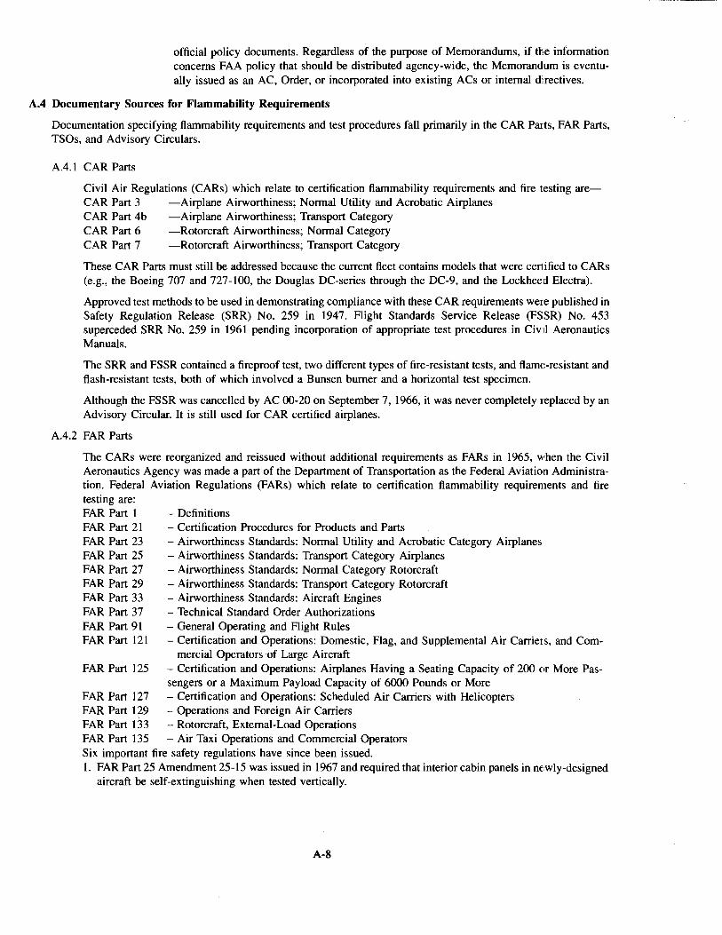
- -- -----~-------------~---~ ---···---·-·---
official policy documents. Regardless of the purpose of Memorandums, if the information concerns FAA policy that should be distributed agency-wide, the Memorandum is eventually issued as an AC, Order, or incorporated into existing ACs or internal di.rectives.
A.4 Documentary Sources for Flammability Requirements
Documentation specifying flammability requirements and test procedures fall primarily in the CAR Pruts, FAR Parts, TSOs, and Advisory Circulars.
A.4.1 CAR Parts
Civil Air Regulations (CARs) which relate to certification flammability requirements and fire testing are-CAR Part 3 -Airplane Airworthiness; Normal Utility and Acrobatic Airplanes CAR Part 4b -Airplane Airworthiness; Transport Category CAR Part 6 -Rotorcraft Airworthiness; Normal Category CAR Part 7 -Rotorcraft Airworthiness; Transport Category
These CAR Parts must still be addressed because the current fleet contains models that were certified to CARs (e.g., the Boeing 707 and 727-100, the Douglas DC-series through the DC-9, and the Lockheed Electra).
Approved test methods to be used in demonstrating compliance with these CAR requirements were published in Safety Regulation Release (SRR) No. 259 in 1947. Flight Standards Service Release (FSSR) No. 453 superceded SRR No. 259 in 1961 pending incorporation of appropriate test procedures in Civlil Aeronautics Manuals.
The SRR and FSSR contained a fireproof test, two different types of fire-resistant tests, and flame-resistant and flash-resistant tests, both of which involved a Bunsen burner and a horizontal test specimen.
Although the FSSR was cancelled by AC 00-20 on September 7, 1966, it was never completely replaced by an Advisory Circular. It is still used for CAR certified airplanes.
A.4.2 FAR Parts
The CARs were reorganized and reissued without additional requirements as FARs in 1965, when the Civil Aeronautics Agency was made a part of the Department of Transportation as the Federal Aviation Administration. Federal Aviation Regulations (FARs) which relate to certification flammability requirements and fire testing are: FAR Part 1 FAR Part 21 FAR Part 23 FAR Part 25 FAR Part 27 FAR Part 29 FAR Part 33 FAR Part 37 FAR Part 91 FAR Part 121
- Definitions - Certification Procedures for Products and Parts -Airworthiness Standards: Normal Utility and Acrobatic Category Airplanes - Airworthiness Standards: Transport Category Airplanes -Airworthiness Standards: Normal Category Rotorcraft - Airworthiness Standards: Transport Category Rotorcraft - Airworthiness Standards: Aircraft Engines - Technical Standard Order Authorizations - General Operating and Flight Rules - Certification and Operations: Domestic, Flag, and Supplemental Air Carriers, and Com-
mercial Operators of Large Aircraft FAR Part 125 - Certification and Operations: Airplanes Having a Seating Capacity of 200 or More Pas-
sengers or a Maximum Payload Capacity of 6000 Pounds or More FAR Part 127 -Certification and Operations: Scheduled Air Carriers with Helicopters FAR Part 129 -Operations and Foreign Air Carriers FAR Part 133 - Rotorcraft, External-Load Operations FAR Part 135 - Air Taxi Operations and Commercial Operators Six important fire safety regulations have since been issued. 1. FAR Part 25 Amendment 25-15 was issued in 1967 and required that interior cabin panels in ne:wly-designed
aircraft be self-extinguishing when tested vertically.
A-8
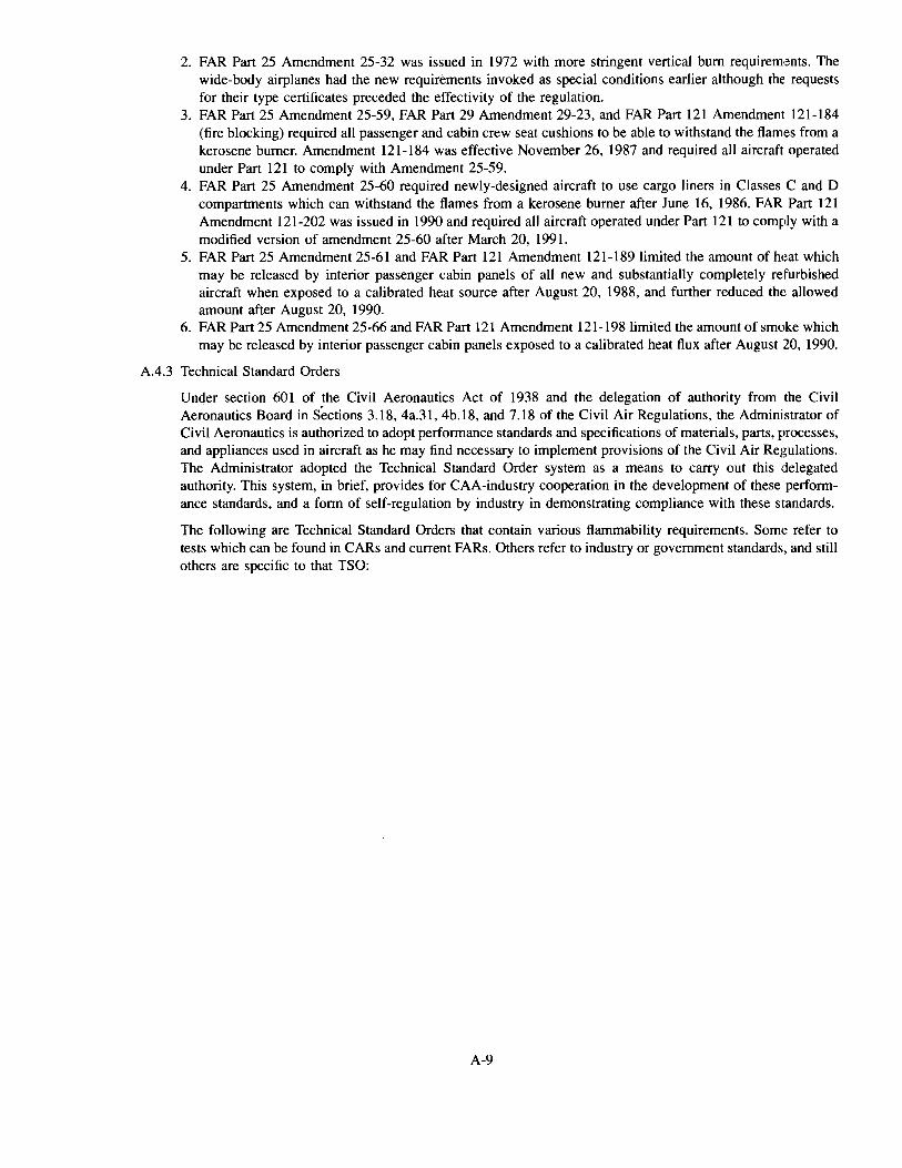
2. FAR Part 25 Amendment 25-32 was issued in 1972 with more stringent vertical bum requirements. The wide-body airplanes had the new requirements invoked as special conditions earlier although the requests for their type certificates preceded the effectivity of the regulation.
3. FAR Part 25 Amendment 25-59, FAR Part 29 Amendment 29-23, and FAR Part 121 Amendment 121-184 (fire blocking) required all passenger and cabin crew seat cushions to be able to withstand the flames from a kerosene burner. Amendment 121-184 was effective November 26, 1987 and required all aircraft operated under Part 121 to comply with Amendment 25-59.
4. FAR Part 25 Amendment 25-60 required newly-designed aircraft to use cargo liners in Classes C and D compartments which can withstand the flames from a kerosene burner after June 16, 1986. FAR Part 121 Amendment 121-202 was issued in 1990 and required all aircraft operated under Part 121 to comply with a modified version of amendment 25-60 after March 20, 1991.
5. FAR Part 25 Amendment 25-61 and FAR Part 121 Amendment 121-189 limited the amount of heat which may be released by interior passenger cabin panels of all new and substantially completely refurbished aircraft when exposed to a calibrated heat source after August 20, 1988, and further reduced the allowed amount after August 20, 1990.
6. FAR Part 25 Amendment 25-66 and FAR Part 121 Amendment 121-198limited the amount of smoke which may be released by interior passenger cabin panels exposed to a calibrated heat flux after August 20, 1990.
A.4.3 Technical Standard Orders
Under section 601 of the Civil Aeronautics Act of 1938 and the delegation of authority from the Civil Aeronautics Board in S~ctions 3.18, 4a.31, 4b.18, and 7.18 of the Civil Air Regulations, the Administrator of Civil Aeronautics is authorized to adopt performance standards and specifications of materials, parts, processes, and appliances used in aircraft as he may find necessary to implement provisions of the Civil Air Regulations. The Administrator adopted the Technical Standard Order system as a means to carry out this delegated authority. This system, in brief, provides for CAA-industry cooperation in the development of these performance standards, and a form of self-regulation by industry in demonstrating compliance with these standards.
The following are Technical Standard Orders that contain various flammability requirements. Some refer to tests which can be found in CARs and current FARs. Others refer to industry or government standards, and still others are specific to that TSO:
A-9
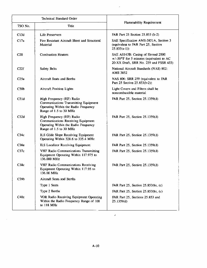
Technical Standard Order Flammability Requirement
TSO No. Title
C13d Life Preservers FAR Part 25 Section 25.853 (b··2)
C17a Fire Resistant Aircraft Sheet and Structural SAE Specification AMS-3851A, Section 3 Material (equivalent to FAR Part 25, Section
25.855(a-1))
C20 Combustiol) Heaters SAE AS143B: Casing of Shroud 2000 +I-50°F for 5 minutes (equivalent to AC 20-XX Draft, SRR No. 259 and FSSR 453)
C22f Safety Belts National Aircraft Standards (NAS) 802: AMS 3852
C25a Aircraft Seats and Berths NAS 806: SRR 259 (equivalent to FAR Part 25 Section 25.853(b-2))
C30b Aircraft Position Lights Light Covers and Filters shall be noncombustible material
C31d High Frequency (HF) Radio FAR Part 25, Section 25.1359(d) Communications Transmitting Equipment Operating Within the Radio Frequency Range of 1.5 to 30 MHz
C32d High Frequency (HF) Radio FAR Part 25, Section 25.1359(d) Communications Receiving Equipment Operating Within the Radio Frequency Range of 1. 5 to 30 MHz
C34c ILS Glide Slope Receiving Equipment FAR Part 25, Section 25 .l359(d) Operating Within 328.6 to 335.4 MHz
C36e ILS Localizer Receiving Equipment FAR Part 25, Section 25.1359(d)
C37c VHF Radio Communications Transmitting FAR Part 25, Section 25 .1359(d) Equipment Operating Within 117.975 to 136.000 MHz
C38c VHF Radio Communications Receiving FAR Part 25, Section 25.1359(d) Equipment Operating Within 117.95 to 136.00 MHz
C39b Aircraft Seats and Berths
Type 1 Seats FAR Part 25, Section 25.853(b), (c)
Type 2 Berths FAR Part 25, Section 25.853(b), (c)
C40c VOR Radio Receiving Equipment Operating FAR Part 25, Sections 25.853 and Within the Radio Frequency Range of 108 25.1359(d) to 118 MHz
/
A-10
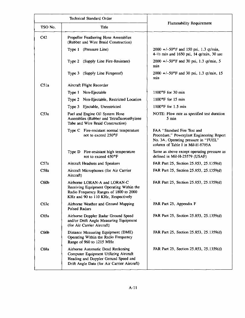
Technical Standard Order Flammability Requirement
TSO No. Title
C42 Propeller Feathering Hose Assemblies (Rubber and Wire Braid Construction)
Type 1 (Pressure Line) 2000 +I-50°F and 150 psi, 1.3 qt/min, 4-1/2 min and 1650 psi, 14 qt/min, 30 sec
Type 2 (Supply Line Fire-Resistant) 2000 +I-50°F and 30 psi, 1.3 qt/min, 5 min
Type 3 (Supply Line Fireproof) 2000 +/-50°F and 30 psi, 1.3 qt/min, 15 min
C51a Aircraft Flight Recorder
Type 1 Non-Ejectable ll00°F for 30 min
Type 2 Non-Ejectable, Restricted Location 1100°F for 15 min
Type 3 Ejectable, Unrestricted ll00°F for 1.5 min
C53a Fuel and Engine Oil System Hose NOTE: Flow rate as specified test duration Assemblies (Rubber and Tetrafluoroethylene 5 min Thbe and Wire Braid Construction)
Type C Fire-resistant normal temperature FAA "Standard Fire Test and not to exceed 250°F Procedure," Powerplant Engineering Report
No. 3A. Operating pressure in "FUEL" column of Table I in Mil-H-8795A
TypeD Fire-resistant high temperature Same as above except operating pressure as not to exceed 450°F defined in Mil-H-25579 (USAF)
C57a Aircraft Headsets and Speakers FAR Part 25, Section 25.853, 25.1359(d)
C58a Aircraft Microphones (for Air Carrier FAR Part 25, Section 25.853, 25.1359(d) Aircraft)
C60b Airborne LORAN-A and LORAN-C FAR Part 25, Section 25.853, 25.1359(d) Receiving Equipment Operating Within the Radio Frequency Ranges of 1800 to 2000 KHz and 90 to 110KHz, Respectively
C63c Airborne Weather and Ground Mapping FAR Part 25, Appendix F Pulsed Radars
C65a Airborne Doppler Radar Ground Speed FAR Part 25, Section 25.853, 25.1359(d) and/or Drift Angle Measuring Equipment (for Air Carrier Aircraft)
C66b Distance Measuring Equipment (DME) FAR Part 25, Section 25.853, 25.1359(d) Operating Within the Radio Frequency Range of 960 to 1215 MHz
C68a Airborne Automatic Dead Reckoning FAR Part 25, Section 25.853, 25.1359(d) Computer Equipment Utilizing Aircraft Heading and Doppler Ground Speed and Drift Angle Data (for Air Carrier Aircraft)
A-11
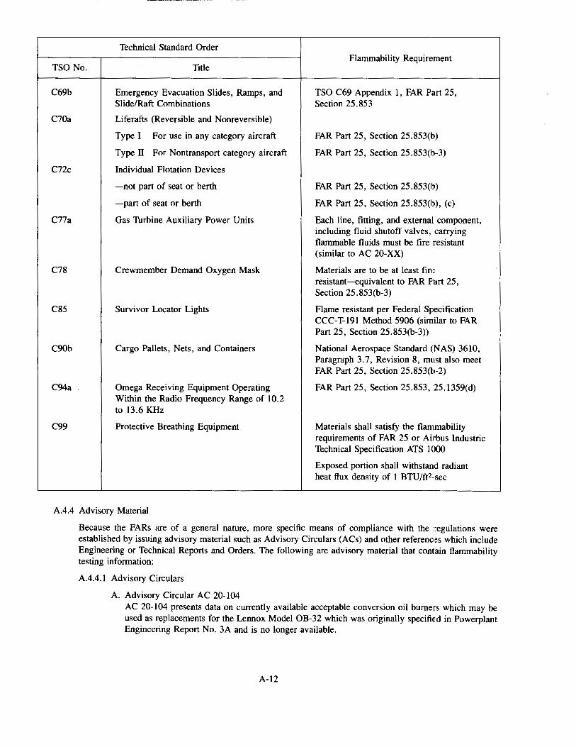
Technical Standard Order Flammability Requirement
TSO No. Title
C69b Emergency Evacuation Slides, Ramps, and TSO C69 Appendix 1, FAR Part 25, Slide/Raft Combinations Section 25.853
C70a Liferafts (Reversible and Nonreversible)
Type I For use in any category aircraft FAR Part 25, Section 25.8530b)
Type II For Nontransport category aircraft FAR Part 25, Section 25.853(b-3)
C72c Individual Flotation Devices
-not part of seat or berth FAR Part 25, Section 25. 853(b)
-part of seat or berth FAR Part 25, Section 25.8530J), (c)
C77a Gas Thrbine Auxiliary Power Units Each line, fitting, and external component, including fluid shutoff valves, carrying flammable fluids must be fire resistant (similar to AC 20-XX)
C78 Crewmember Demand Oxygen Mask Materials are to be at least fire resistant-equivalent to FAR P'art 25, Section 25.8530b-3)
C85 Survivor Locator Lights Flame resistant per Federal Specification CCC-T-191 Method 5906 (similar to FAR Part 25, Section 25.8530b-3))
C90b Cargo Pallets, Nets, and Containers National Aerospace Standard (NAS) 3610, Paragraph 3. 7, Revision 8, must also meet FAR Part 25, Section 25.853(b-2)
C94a Omega Receiving Equipment Operating FAR Part 25, Section 25.853, 25.1359(d) Within the Radio Frequency Range of 10.2 to 13.6 KHz
C99 Protective Breathing Equipment Materials shall satisfy the flammability requirements of FAR 25 or Airbus Industrie Technical Specification ATS 1000
Exposed portion shall withstand radiant heat flux density of 1 BTU/ft2-sec
A.4.4 Advisory Material
Because the FARs are of a general nature, more specific means of compliance with the regulations were established by issuing advisory material such as Advisory Circulars (ACs) and other references which include Engineering or Technical Reports and Orders. The following are advisory material that contain flammability testing information:
A.4.4.1 Advisory Circulars
A. Advisory Circular AC 20-104 AC 20-104 presents data on currently available acceptable conversion oil burners which may be used as replacements for the Lennox Model OB-32 which was originally specified in Powerplant Engineering Report No. 3A and is no longer available.
A-12
B. Advisory Circular AC 20-135, "Power Plant Installation and Propulsion System Fire Protection Test Methods, Standards, and Criteria."
C. Advisory Circular AC 23-2, "Flammability Tests" AC-23-2 provides information and guidance concerning an acceptable means of compliance with CAR Part 3 and FAR Part 23 applicable to flammability tests for various materials, components, and electrical wire. The AC incorporates pertinent sections of FSSR 453, Federal Test Method Standard No. 191A, SAE Aerospace Standard (AS) 1055B, and SAE Aerospace Information Report (AIR) 1377 A.
D. Advisory Circular AC 25.853.1, "Flammability Requirements for Aircraft Sea Cushions" AC 25.853.1 was issued to provide guidance in complying with FAR Part 25 Paragraph 25.853(c) and FAR Part 25, Appendix F, Part II, fire blocking seat cushion requirement published in Amendment 25-59.
A.4.4.2 Orders
Order No. 8120.7, "Control of Composite Raw Materials," was issued to provide interim guidance to all manufacturing inspection personnel regarding the level of testing and documentation necessary to establish conformance to applicable specifications of raw material used in the fabrication of composite products by FAA production approval holders and/or applicants for approvals. This guidance material is consistent with current directives and advisory circulars (AC 20-107 A) concerning FAA production approval holders' responsibilities.
A.4.4.3 Engineering Reports
TSOs C42, C53a, and C75 required further clarification regarding testing of flexible hoses leading to the release by the FAA of Power Plant Engineering Report No. 3A, "Standard Fire Test Apparatus and Procedure (For Flexible Hose Assemblies)." This report contains a complete description of the standard fire test apparatus and procedure aimed at producing a typical aircraft power plant fire, vibration of the type encountered during rough engine operation, and the various flight conditions of fluid flow, pressure, and temperature.
A-13
This page intentionally left blank
A-14
B.l Introduction
APPENDIX B The Approval Process
In the Federal Aviation Act of 1958, a complex multistep approval/certification process was established for the FAA to follow to ensure that civil aircraft meet minimum safety requirements. These regulations are found in 14 CFR (Code of Federal Regulations), which comprise the FARs (Federal Aviation Regulations). 14 CFR Parts are commonly referred to as FAR Parts.
The regulatory requirements that civil aircraft must meet depend on the type of aircraft involved (i.e., light airplanes, large multipassenger airplanes, helicopters, etc.), and the aircraft's intended use (i.e., private, crop dusting, airline, external load-bearing helicopters, etc.). A detailed description of the approval steps and procedures is beyond the scope and needs of this handbook. However, a general description is given, with appropriate details relevant to approval steps and procedures requiring flammability testing.
The basic premise of the regulations is that each individual aircraft must be approved. Except for "public aircraft" (i.e., those operated by the federal, state, or local government), all civil aircraft must be approved by the FAA before they may be placed into any service. To acquire the necessary approvals, it must have been demonstrated to the FAA via the multistep approval process that the aircraft complies with the appropriate regulatory requirements.
The FAA is not set up or intended to have responsibility for carrying out the various steps in the approval pro,:ess. The FAA's function is essentially to review and approve designs, test and production hardware, and test plans, and to witness tests and approve test data. The primary responsibility for carrying out the necessary demonstrations of compliance lies with the aircraft manufacturers and operators. Manufacturers perform some of the approval steps, and aircraft operators perform the others.
B.2 Approval Steps-Manufacturers
The manufacturer of each aircraft produced must receive FAA approval for that aircraft before it can be operated by its owner/operator. The regulatory requirements are covered in the FAR parts dealing with Airworthiness Standards. The procedures are defined in FAR Part 21, Certification Procedures for Products and Parts.
Manufacturers are responsible for carrying out, and receiving FAA approval of, the several steps involved with the design and manufacture of aircraft.
B.2.1 Certification Requirements
Airworthiness Standards contain performance requirements for the certification of aircraft. The FAR Parts dealing with Airworthiness Standards are-
FAR Part 23 Airworthiness Standards: Normal Utility and Acrobatic Category Airplanes
FAR Part 25 Airworthiness Standards: Transport Category Airplanes
FAR Part 27 Airworthiness Standards: Normal Category Rotorcraft
FAR Part 29 Airworthiness Standards: Transport Category Rotorcraft
FAR Part 33 Airworthiness Standards: Aircraft Engines
FAR Part 35 Airworthiness Standards: Propellers
Airworthiness Standards are amended from time to time to modify (upgrade, clarify, etc.) the requirements. The regulatory requirements that a specific aircraft must comply with are established by the amendment level of the applicable FAR Part which applies to that aircraft, plus any special conditions that may be levied by the FAA on that aircraft for its certification. These requirements are known as the "regulations incorporated by reference" which are identified on the aircraft's Type Certificate data sheet (see Section B.2.2.1 ).
B.2.2 Certification Procedures
The basic item which the FAA approves is the aircraft. Aircraft parts are not "approved" in the same sense, since a review of aircraft components for compliance to a set of requirements is only done in conjunction with
B-1
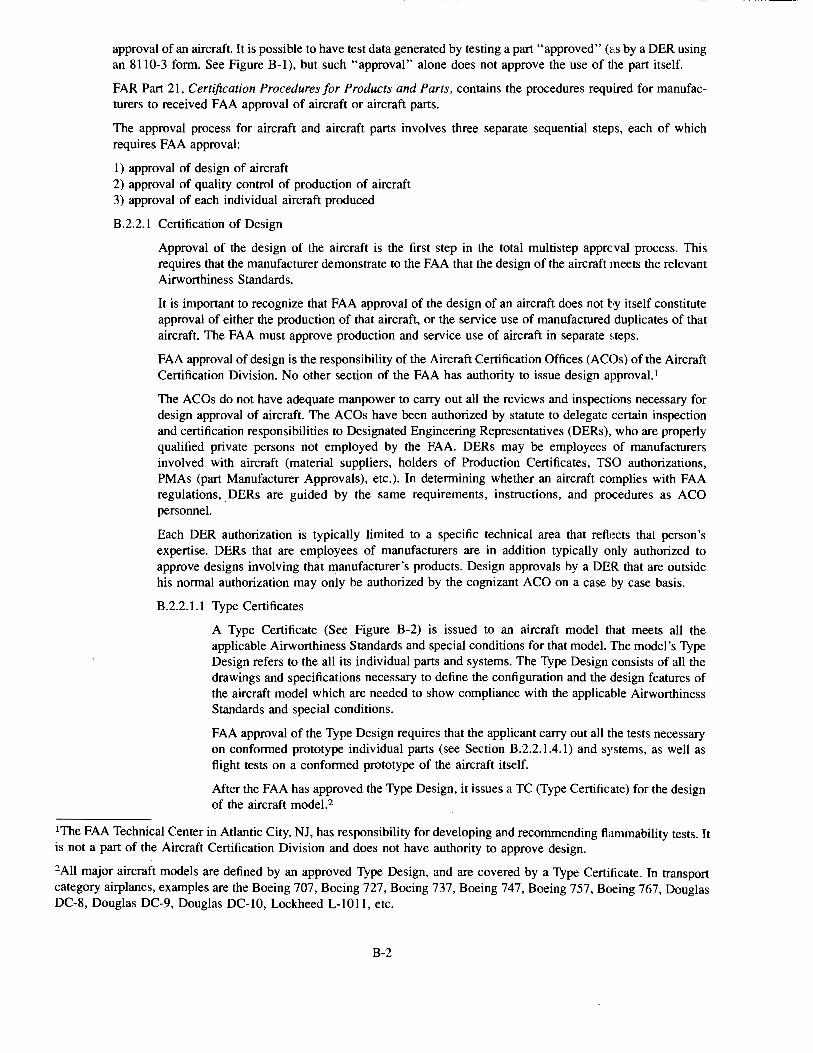
approval of an aircraft. It is possible to have test data generated by testing a part "approved" (~ts by a DER using an 8110-3 form. See Figure B-1), but such "approval" alone does not approve the use of the part itself.
FAR Part 21, Certification Procedures for Products and Parts, contains the procedures required for manufacturers to received FAA approval of aircraft or aircraft parts.
The approval process for aircraft and aircraft parts involves three separate sequential steps, each of which requires FAA approval:
1) approval of design of aircraft 2) approval of quality control of production of aircraft 3) approval of each individual aircraft produced
B.2.2.1 Certification of Design
Approval of the design of the aircraft is the first step in the total multistep approval process. This requires that the manufacturer demonstrate to the FAA that the design of the aircraft meets the relevant Airworthiness Standards.
It is important to recognize that FAA approval of the design of an aircraft does not by itself constitute approval of either the production of that aircraft, or the service use of manufactured duplicates of that aircraft. The FAA must approve production and service use of aircraft in separate steps.
FAA approval of design is the responsibility of the Aircraft Certification Offices (A COs) of the Aircraft Certification Division. No other section of the FAA has authority to issue design approval. I
The ACOs do not have adequate manpower to carry out all the reviews and inspections necessary for design approval of aircraft. The ACOs have been authorized by statute to delegate certain inspection and certification responsibilities to Designated Engineering Representatives (DERs), who are properly qualified private persons not employed by the FAA. DERs may be employees of manufacturers involved with aircraft (material suppliers, holders of Production Certificates, TSO authorizations, PMAs (part Manufacturer Approvals), etc.). In determining whether an aircraft complies with FAA regulations, DERs are guided by the same requirements, instructions, and procedures as ACO personnel.
Each DER authorization is typically limited to a specific technical area that reflects that person's expertise. DERs that are employees of manufacturers are in addition typically only authorized to approve designs involving that manufacturer's products. Design approvals by a DER that are outside his normal authorization may only be authorized by the cognizant ACO on a case by case basis.
B.2.2.1.1 Type Certificates
A Type Certificate (See Figure B-2) is issued to an aircraft model that meets all the applicable Airworthiness Standards and special conditions for that model. The model's Type Design refers to the all its individual parts and systems. The Type Design consists of all the drawings and specifications necessary to define the configuration and the design features of the aircraft model which are needed to show compliance with the applicable Airworthiness Standards and special conditions.
FAA approval of the Type Design requires that the applicant carry out all the tests necessary on conformed prototype individual parts (see Section B.2.2.1.4.1) and systems, as well as flight tests on a conformed prototype of the aircraft itself.
After the FAA has approved the Type besign, it issues a TC (Type Certificate) for the design of the aircraft model,2
1The FAA Technical Center in Atlantic City, NJ, has responsibility for developing and recommending flammability tests. It is not a part of the Aircraft Certification Division and does not have authority to approve design.
2All major aircraft models are defined by an approved Type Design, and are covered by a Type Certificate. In transport category airplanes, examples are the Boeing 707, Boeing 727, Boeing 737, Boeing 747, Boeing 757, Boeing 767, Douglas DC-8, Douglas DC-9, Douglas DC-10, Lockheed L-1011, etc.
B-2
B.2.2.1.2 Amended Type Certificates
If a holder of the Type Certificate covering an aircraft model wishes to make a major change in the Type Design (not great enough to require a new Type Certificate) of the aircraft, an amended Type Certificate covering the revised Type Design is required. 3
The applicant for an amended Type Certificate must show that the aircraft continues to comply with the regulations incorporated by reference plus any additional requirements such as amendments to the Airworthiness Standards and/or special conditions that were not included in the original Type Design.
The procedure for obtaining an amended Type Certificate is basically the same as for obtaining Type Certificates.
B.2.2.1.3 Supplemental Type Certificates
If a party wishes to make a major change in the Type Design of an aircraft model (not great enough to require a new Type Certificate), and the party is not the holder of the Type Certificate for that aircraft model, approval of the change requires a Supplemental Type Certificate (STC). A holder of a Type Certificate who wishes to make a change in the Type Design that is less than that involving derivative aircraft may also apply for a STC.
Supplemental Type Certificates in practice are used for specific design features of the aircraft, and do not as a rule involve modifications to other, unaffected design features of the aircraft.4
B.2.2.1.4 Individual Aircraft Parts
Individual aircraft parts are not "approved" by the FAA; only the aircraft on which the part is used is approved.
To obtain approval for use of a part on an aircraft, the applicant must comply with the Type Design of the aircraft on which they are to be installed. The applicant5 must apply to an FAA ACO (Aircraft Certification Office) for approval of the design of the part. The application must include a complete formal description (.:.g., drawing or drawings) of the design, and the aircraft on which the part is to be installed. The design must be sufficiently definitive and unambiguous to define the item and the requirements which it must satisfy.
B.2.2.1.4.1 Conformity Inspection
If testing of the part is required, the applicant must provide a fabricated prototype of the part along with an FAA 8130-9 form (Statement of Conformity) (See Figure B-3) stating that the prototype conforms with the design (i.e., was fabricated using the materials and processes prescribed in the formal description of the design). An FAA Manufacturing Inspector or his designee must then
3This procedure is often used for certification of derivative aircraft models. In transport category airplanes, for example, follow-on versions of the Boeing 737, Boeing 747, Boeing 757, and Boeing 767 were certified by amended Type Certificates to their respective basic Type Designs. The follow-on versions of the Douglas DC-9, including the Douglas MD-80 series, were certified by amended Type Certificates to the basic Douglas DC-9 Type Design.
4This procedure is often used for certification of specific but relatively major changes to the aircraft's design. In transport category airplanes, for example, it has been used to certify modified evacuation slide systems for the Boeing 7tJ.-7. The slide manufacturer applied for and was granted a STC. The manufacturer had to show that replacing the slide in the original 747 design with his slide met all the applicable requirements.
5The "applicant" who applies to the FAA for approval of the design of a part is the party who accepts responsibility to the FAA for the Production Conformity to Type Design of the end item. The FAA does not issue approval of the design of individual aircraft parts to manufacturers who do not also have some FAA coverage for producing them (such as a STC, TSO, or PMA). The "applicant" may or may not be the party that actually fabricates the end item.
B-3
examine the prototype (and any required accompanying evidence) to determine whether the demonstration of its conformity is satisfactory. If satisfactory, the Manufacturing Inspector6 (or his designee) will effect an FAA 8130-3 form (Conformity Certification) (See Figure B-4) stating that the prototype is in conformity.
After conformity of the prototype has been established, any required tests may be performed to demonstrate that it complies with the applicable regulations. The applicant must provide arrangements for the testing by an appropriate and FAA-approved test facility, and coordinate the date and time with the FAA ACO or its designee for test witnessing.
B.2.2.1.4.2 Test Plan Preparation
Any required tests must be performed on a prototype of the part to demonstrate that it complies with the applicable regulations. The applicant must prepare a test plan which includes the following information:
A. Title, list of active pages, and revision record
B. The exact part usage, including aircraft model, and FAR flammability requirements including the amendment level
C. The test procedure and the FAA-approved test facility to be used. The test date shall be coordinated with the FAA ACO or its designee for test witnessing.
D. Detailed and complete identification of material(s) used for part construction (a copy of the conformity inspection approval may be inclUtded; see Section B.2.2.1.4.1)
E. An isometric sketch of the part with all individual test constructions/panels numerically identified, if the part to be certified requires that more than one construction be tested, such as a galley.
In order to facilitate completing a test report (see Section B.2.2.1.4.3) upon completion of testing, data sheets for each test and each construction may be provided. The data sheet must be completely filled out with the exception of the test results. When the test results are entered and signed by the FAA witness or FAA designee (DER), the test plan may be used as the test report.
B.2.2.1.4.3 Test Report
If the results of the test show the prototype to be in compliance, a test report identifying the part and presenting the data must be prepared. If the test plan is completed in accordance with B.2.2.1.4.2, the test plan may be modified to become a test report by completing the test data sections on the data sheets provided. The ACO will then approve the part (usually as part of a Type Certificate or a Supplemental Type Certificate activity), or its DER designee will effect an FAA 8110-3 form (Statement of Compliance with the Federal Aviation Regulations) (See Figure B-1) which indicates approval that the design of the
6Neither the FAA Aircraft Certification Office nor its DER (Designated Engineering Representatives) designees have the authority to perform conformity inspections; that must be done by the FAA Manufacturing Inspection Office or its DMIR (Designated Manufacturing Inspection Representatives) designees. The Manufacturing Inspection Office at tint conditis, but the practice is not widespread.
B-4
item satisfies the specific requirement(s) ofthe regulations that the test covered.? The ACO itself does not issue a 8110-3 form; only DERs do that.
B.2.2.1.5 Technical Standard Orders
A Technical Standard Order (TSO) is a minimum performance standard for specified articles (i.e., materials, parts, processes, or appliances) used on civil aircraft. The performance standards stated in the TSO reflect some (but not necessarily all) of the requirements for that article stated in the Airworthiness Standards.
A TSO authorization is an FAA acknowledgment that the design of the article meets the specified minimum performance standard in the TSO, and that the TSO holder may produce and mark the authorized article with the TSO designation.
It is important to recognize, however, that since amendments to the Airworthiness Standards and to the TSOs are made independently by the FAA, there may be situations when TSO requirements and Airworthiness Standards are not the same. In such a case, approval of the article may involve requirements beyond those of the TSO itself.
TSOs involving flammability include the following:
TSO C10a Life Rafts (Nonreversible) TSO C 13c Life Preservers TSO C 13d Life preservers TSO C17a Fire Resistant Aircraft Sheet and Structural Material TSO C20 Combustion Heaters TSO C22f Safety Belts TSO C25a Aircraft Seats and Berths TSO C30b Aircraft Position Lights TSO C31d High Frequency (HF) Radio Communications Transmitting Eqlllipment TSO C32d High Frequency (HF) Radio Communications Receiving Equipment TSO C34c ILS Glide Slope Receiving Equipment TSO C36e ILS Localizer Receiving Equipment TSO C37c VHF Radio Communications Transmitting Equipment TSO C38c VHF Radio Communications Receiving Equipment TSO C39b Aircraft Seats and Berths TSO C40c VOR Radio Receiving Equipment TSO C42 Propeller Feathering Hose Assemblies TSO C51a Aircraft Flight Recorder TSO C53a Fuel and Engine Oil System Hose Assemblies TSO C57a Aircraft Headsets and Speakers TSO C58a Aircraft Microphones TSO C60b Airborne LORAN-A and LORAN-C Receiving Equipment TSO C63c Airborne Weather and Ground Mapping Pulsed Radars TSO C65a Airborne Doppler Radar Ground Speed and/or Drift Angle Measuring
Equipment TSO C66b Distance Measuring Equipment (DME) TSO C68a Airborne Automatic Dead Reckoning Computer Equipment TSO C69b Emergency Evacuation Slides. Ramps, and Slide/Raft Combinations
7The test(s) performed may not cover all the regulaty requirements which the item must meet. For example, per FAR 121 Amendment 198 cabin sidewall liners for tranort category airplanes that are manufactured after August 20, 1990, must comply with FAR 25 Amendment 32 (which involves a Bunsen burner test) and with FAR 25 Amendment 66 (which involves a heat release test and a smoke release test). The three tests may be covered by a single 8110-3 form; however, two or three separate 8110-3 forms may be requried if the tests are carried out at different times and in different places. The operator of the airplane produces 8110-3 form(s) that cover all three requirements before the airplane can be placed in service.
B-5

TSO C70a Liferafts (Reversible and Nonreversible) TSO C72c Individual Flotation Devices TSO C75 Hydraulic Hose Assemblies TSO C77a Gas Turbine Auxiliary Power Units TSO C78 Crewmember Demand Oxygen Mask TSO C85 Survivor Locator Lights TSO C90b Cargo Pallets, Nets, and Containers TSO C94a Omega Receiving Equipment TSO C99 Protective Breathing Equipment
B.2.2.1.6 Parts Manufacturer Approval
A Parts Manufacturer Approval (PMA) covers FAA approval for the production of certain materials, parts, processes, and appliances. A PMA application requires that the applicant submit for FAA approval the identity of the aircraft on which the part is to be installed, sufficient information defining the design of the part, and FAA-approved test data showing that the design of the part complies with all the Airworthiness Standards and special conditions applicable to the aircraft on which the part is to be installed.
B.2.2.2 Certification of Production Quality Control
FAA approval of production requires essentially the approval of the manufacturer's production quality control system. The mechanisms of approval vary depending on whether the manufacturer holds a Production Certificate, Technical Standard Order authorization, or Parts Manufacturer Approval. The details are not important for the purposes of this handbook.
The purpose of the quality control system is to ensure consistent satisfactory production of all items involving FAA-approved designs.
In his quality control system, the manufacturer must provide for systematic monitoring of materials and processing to ensure that production goods meet their individual design requirements. The procedures used, including the frequency of inspections, must be documented and presented to the FAA for approval. Any changes in the quality control system must also be submitted to the FAA for approval.
FAA approval of a manufacturer's production quality control system is the responsibility of the Manufacturing Inspection Offices of the Manufacturing Inspection Branch. No other section of the FAA, including the Aircraft Certification Division, has authority to approve a production quality control system.
The Manufacturing Inspection Offices, like the ACOs, do not have adequate manpower to carry out all the reviews and inspections necessary for approval and monitoring of production quality control systems. The Manufacturing Inspection Offices have been authorized by statute to delegate certain inspection and monitoring responsibilities to Designated Manufacturing Inspection Representatives (DMIRs), who are properly qualified private persons. DMIRs may be employees of manufacturers involved with aircraft (material suppliers, holders of Production Certificates, TSO authorizations, PMAs, etc.) In determining whether an aircraft or aircraft part complies with FAA regulations, DMIRs are guided by the same requirements, instructions, and procedures as Manufacturing Inspection Office personnel.
B.2.2.3 Certification of Individual Aircraft
Each individual aircraft must receive FAA approval before it can be placed into any service. If there are minor design differences between the actual produced aircraft and the Type Design used for the aircraft's Type Certificate, the ACO or its designee(s) must approve the design modifications.
The approval of the aircraft itself takes the form of an Airworthiness Certificate (FAA 8100-2 form), as shown in Figure B-5, which signifies that the aircraft was manufactured according to the engineering drawings defining it, and therefore complies with the applicable Airworthiness Standards artd all special conditions that may apply to that aircraft.
B-6
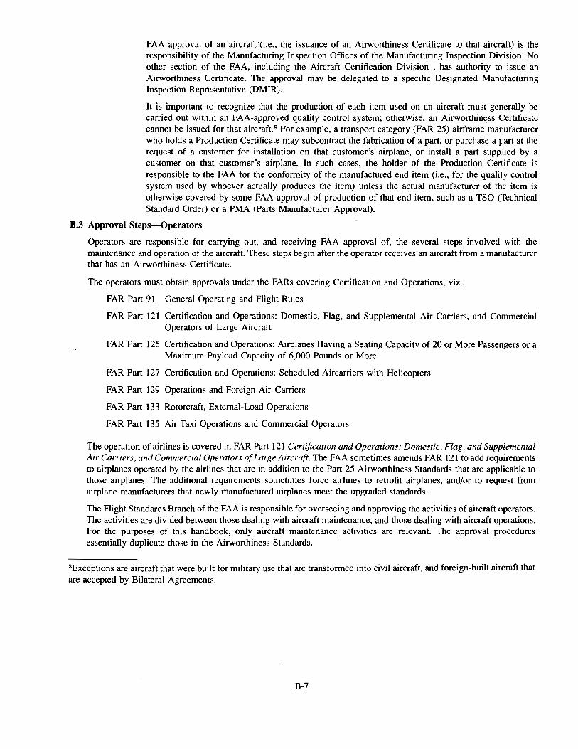
FAA approval of an aircraft (i.e., the issuance of an Airworthiness Certificate to that aircraft) is the responsibility of the Manufacturing Inspection Offices of the Manufacturing Inspection Division. No other section of the FAA, including the Aircraft Certification Division , has authority to issue an Airworthiness Certificate. The approval may be delegated to a specific Designated Manufacturing Inspection Representative (DMIR).
It is important to recognize that the production of each item used on an aircraft must generally be carried out within an FAA-approved quality control system; otherwise, an Airworthiness Certificate cannot be issued for that aircraft.S For example, a transport category (FAR 25) airframe manufacturer who holds a Production Certificate may subcontract the fabrication of a part, or purchase a part at the request of a customer for installation on that customer's airplane, or install a part supplied by a customer on that customer's airplane. In such cases, the holder of the Production Certificate is responsible to the FAA for the conformity of the manufactured end item (i.e., for the quality control system used by whoever actually produces the item) unless the actual manufacturer of the item is otherwise covered by some FAA approval of production of that end item, such as a TSO (Technical Standard Order) or a PMA (Parts Manufacturer Approval).
B.3 Approval Steps-Operators
Operators are responsible for carrying out, and receiving FAA approval of, the several steps involved with the maintenance and operation of the aircraft. These steps begin after the operator receives an aircraft from a manufacturer that has an Airworthiness Certificate.
The operators must obtain approvals under the FARs covering Certification and Operations, viz.,
FAR Part 91 General Operating and Flight Rules
FAR Part 121 Certification and Operations: Domestic, Flag, and Supplemental Air Carriers, and Commercial Operators of Large Aircraft
FAR Part 125 Certification and Operations: Airplanes Having a Seating Capacity of 20 or More Passengers or a Maximum Payload Capacity of 6,000 Pounds or More
FAR Part 127 Certification and Operations: Scheduled Aircarriers with Helicopters
FAR Part 129 Operations and Foreign Air Carriers
FAR Part 133 Rotorcraft, External-Load Operations
FAR Part 135 Air Taxi Operations and Commercial Operators
The operation of airlines is covered in FAR Part 121 Certification and Operations: Domestic, Flag, and Supplemental Air Carriers, and Commercial Operators of Large Aircraft. The FAA sometimes amends FAR 121 to add requirements to airplanes operated by the airlines that are in addition to the Part 25 Airworthiness Standards that are applicable to those airplanes. The additional requirements sometimes force airlines to retrofit airplanes, and/or to request from airplane manufacturers that newly manufactured airplanes meet the upgraded standards.
The Flight Standards Branch of the FAA is responsible for overseeing and approving the activities of aircraft operators. The activities are divided between those dealing with aircraft maintenance, and those dealing with aircraft operations. For the purposes of this handbook, only aircraft maintenance activities are relevant. The approval procedures essentially duplicate those in the Airworthiness Standards.
8Exceptions are aircraft that were built for military use that are transformed into civil aircraft, and foreign-built aircraft that are accepted by Bilateral Agreements.
B-7
U.S. DEPARTMENT Of TRANSPORTATION DATE
FEDERAL AVIATION ADMINISTRATION
STATEMENT OF COMPLIANCE WITH THE FEDERAL AVIATION REGULATIONS
AIRCRAFT OR AIRCRAFT COMPONENT IOENTIFICATION MAKE MODEL NO. I TYPE (Airplane, Rodio, Holl<oPior, NAME OF APPLICANT
etc:.)
LIST OF OATA
IDENTIFICATION TITLE
PURPOSE OF DATA
APPLICABLE REQUIREMENTS (LI•I epecltlc eecflone)
CERTIFICATION • Under authority vested by direction olthe Administrator and in accordance with conditions and limitations of appointment under Part 183 of the Federal Aviation Regulations, data listed above and on attached sheets numbered ---
have been examined in ac.cordance with established procedures and found to comply with ap\)licablc requirements of the Federal Aviation ReRulations.
I (We) Therelore 0 Recommend approval of these data 0 Approve these data
SIGNATURE(S) OF DE SIGNA TED ENGINEERING REPRESENTATNE(S) DESIGNATION NUMBERS(S) CLASSIFICATION(S)
-
FAA Form 8110·3 111•701 SUPERSEDES PREVIOUS EDITION
Figure B-1. FAA Form 8110-3 (Statement of Compliance)
B-8
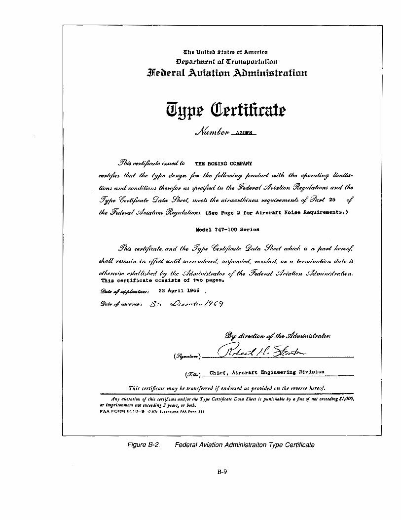
lrlte Unitell !-tatu of America
iltpurtmrnt of lr:runsportution
1J1.e1ternl Auintinn Ailministratinn
Wypr <trrrtifiratr
THE BOEING COMPANY
ctntl{lle; tltat tk lyjte deJt?n fi''~' tlte _l;llou:in? ft1'«kcl u:ilk the ojt-alin!/ linu't.z..
m.nJ and conddt"onJ tlum/o~t aJ yzea/U?d in tk ffed6~tal drialion f!4tyulalionJ and Me
.9'ifte ctfelll¢'azle qala !llzeet, meea the ae·pu:olllfu·neJJ HfjUt'I'BIIlC~ of' [!la,t 25 ·I tlte ~lel'«f Utrialion ~ulam.m. (See Page 2 for Aircraft Noise Requirements.)
Model 747-100 Series
S'ltt;, oo~tlijlcale, am/ lite .?/j;jte 'lfel'ttj/eale ~afa !IJ,eet wluclt iJ, a jtaltllteJte<{.
Jltall 1'emai11 t?t effict unit/ Jttl'l'endeHd, JttJjzended, l'e/tOJ.ed, Oil a lenni11altcm dale iJ,
olltendJe eJia!lt;lted !!I tlte ddmimJlYaloJ< c/ tk .?/"edeJ<tr! ,:;/i:ialtcn ..;Jdnu·niJll'ali<m. This certificate consists of two pages.
~.,l..y"~4Dw.· 22 April 1966 .
!lkAT_,I~.,_.. 3t' ~.--<'_,~ .. /9C?
flAy ,eli~-¥' .the-.9/dminis~(
(S"~)--"""cP::........:;.&:.___d_..:._·~-..:_/_f_:::::~:...:..:..w.--_· ----·
(9iU..) -~C:.::h:.:i:.:e:.::f'-'-'-A-=i-=r-=c.::cr_af.::ct_En--'g"-i_n_e_e_r_i_n....:g:.._D_i_v_i_s_i_o_n ___ _
This ctrtificalt may bt transjtrrtd if mdorud as providtd on tht rtvtrst htrtoj.
dny 11/ttrlltioll of this ((r/ijitlllt lind/or tlu Type Ctrlijitlllt Dll/11 Slut/ is punisl.dlt 6y 11jint of not tJuttding $1,000, or imprisonmtnt nDI tK((tding J yt11rs, or 6otiJ. FAA FORM 811o-9 C7·671 SUPUtUOll FAA FOIM 331
Figure B-2. Federal Aviation Administraiton Type Certificate
B-9
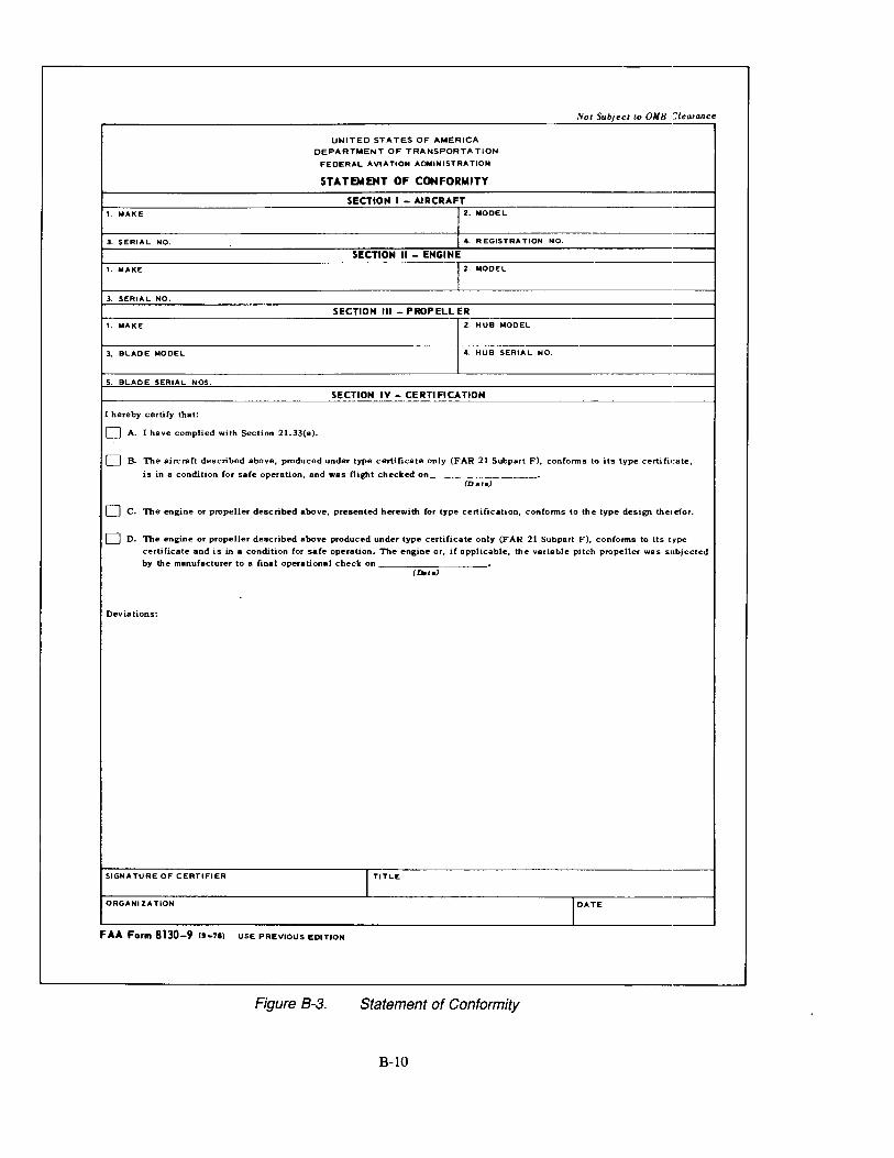
Not Subject to OMB Clearance
UNITED STATES OF AMERICA
DEPARTMENT OF TRANSPORTATION
FEDERAL AVIATION ADMINISTRATION
STA TEMEHT OF CONFORMITY
SECTION I -AIRCRAFT 1. MAKE 2. MODEL
3. SERIAL NO. 4. A EGISTAA TION NO.
SECTION II- ENGINE 1. MAKE 2. MODEL
3. SERIAL NO.
SECTION Ill- PROPELLER --1. MAKE 2. HUB MODEL
3. BLADE MODEL 4. HUB SERIAL NO.
s. BLADE SERIAL NOS.
SECTION IV-CERTIFICATION
I hereby certify that:
0 A. I have complied with Section 21.33(a).
0 B. The aircraft described above, produced under type certificate only (FAR 21 Subpart F), conforms to its type certificate,
is in a condition for safe operation, and was flight checked on~~---------• (Date)
0 c. The engine or propeller described above, presented herewith for type certification, conforms to the type design the•·efor.
0 D. The engine or propeller described above produced under type certificate only (FAR 21 Subpart F), conforms to its type
certificate and is in a condition for safe operation. The engine or, if applicable, the variable pitch propeller was subjected by the manufacturer to a final operational check on
(Dote)
Deviations:
SIGNATURE OF CERTIFIER I TITLE
ORGANIZATION I DATE
FAA Form 8130-9 19-71) USE PREVIOUS EDITION
Figure B-3. Statement of Conformity
B-10
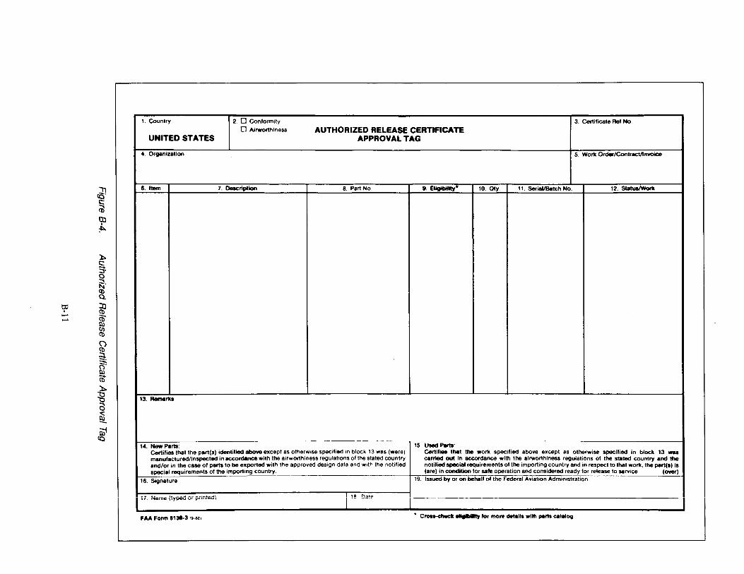
1. Country 2. 0 Conformity 3. Certificate Ref No.
0 Airworthiness AUTHORIZED RELEASE CERTIFICATE UNITED STATES APPROVAL TAG
4. Organization 5. Work Order/Contract/lnvoice
~ 6. Item 7. Description 8. Part No. 9. Eligibility* 10. Qty. 11. Serial/Batch No. 12. Status/Wortl
c:: (i3 OJ '
:1::>.
):. c:: s 0
~· (D Q..
t:P lJ ' (D - CD" - I:U
(/) (D
(") (D
:3-. ~ I:U (ii ):. :g 13. Remarks
a ~ mt
(Q 14. New Parts: 15. u-1 Parts:
Certifies that the part(s) identified above except as otherwise specified in block 13 was (were) Certifies that the work specified above except as otherwise specified in block 13 was manufactured/inspected in accordance with the airworthiness regulations ol the stated country carried out in accordance with the airworthiness regulations of the stated country and the and/or in the case of parts to be exported with the approved design data and with the notified notified special requirements ol the importing country and in respect to that work, the part(s) is special requirements of the importing country. (are) in condition lor sale operation and considered ready lor release to service. (over)
16. Signature t9. Issued by or on behalf of the Federal Aviation Administration
·- .. .. J .. _ ..... , 10 1""1 ....... I"· '"'"'" \lYP"" '" "'"""''' I ·~ ~"" ,--- I
FAA Form 1130-3 ,. ... , · C........,._. ellglllllly tor mo,. ~tells wllll perta caiiiiOil
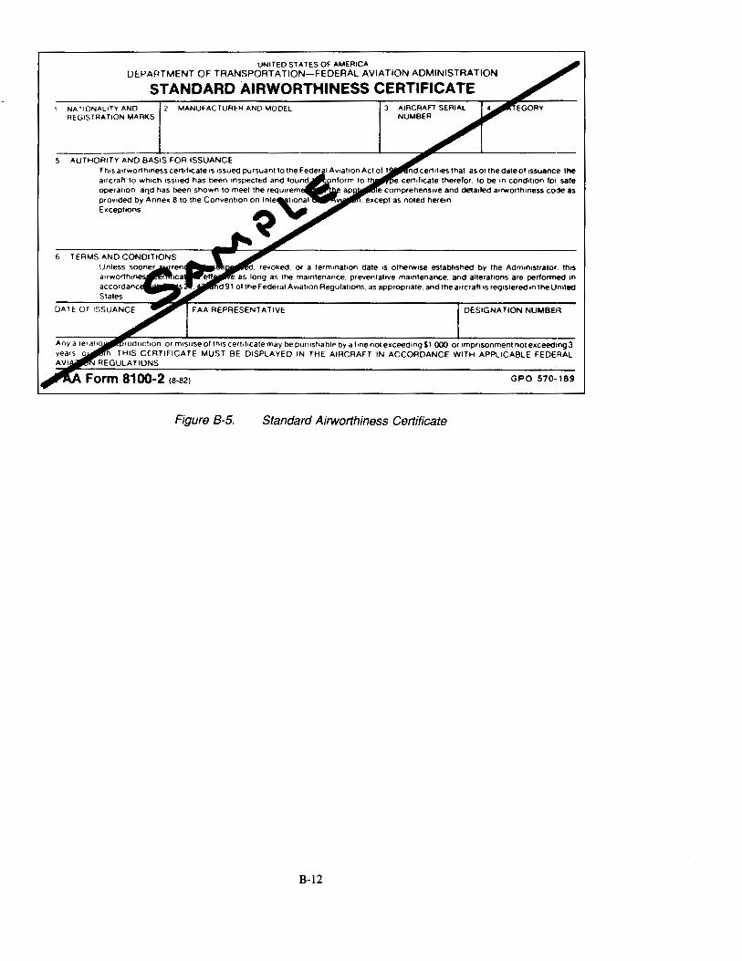
UNITED STATES OF AMERICA DEPARTMENT OF TRANSPORTATION-FEDERAL AVIATION ADMINISTR.o\TION
STANDARD AIRWORTHINESS CERTIFICATE NATIONALITY AND REGISTRATION MARKS
MANUFACTURER AND MODEL 3 AIRCRAFT SERIAL NUMBER
5 AUTHORITY AND BASIS FOR ISSUANCE
6
DESIGNATION NUMBEI'l
roductron or mrs use of thrs certrlrcate may be punrshable by a lone not exceedrng $1.000. or rmpnsonment not exceedmg3 THIS CERTIFICATE MUST BE DISPLAYED IN THE AIRCRAFT IN ACCORDANCE WITH APPLICABLE FEDEI~AL
REGULATIONS
GPO 570-189
Figure B-5. Standard Airworthiness Certificate
B-12
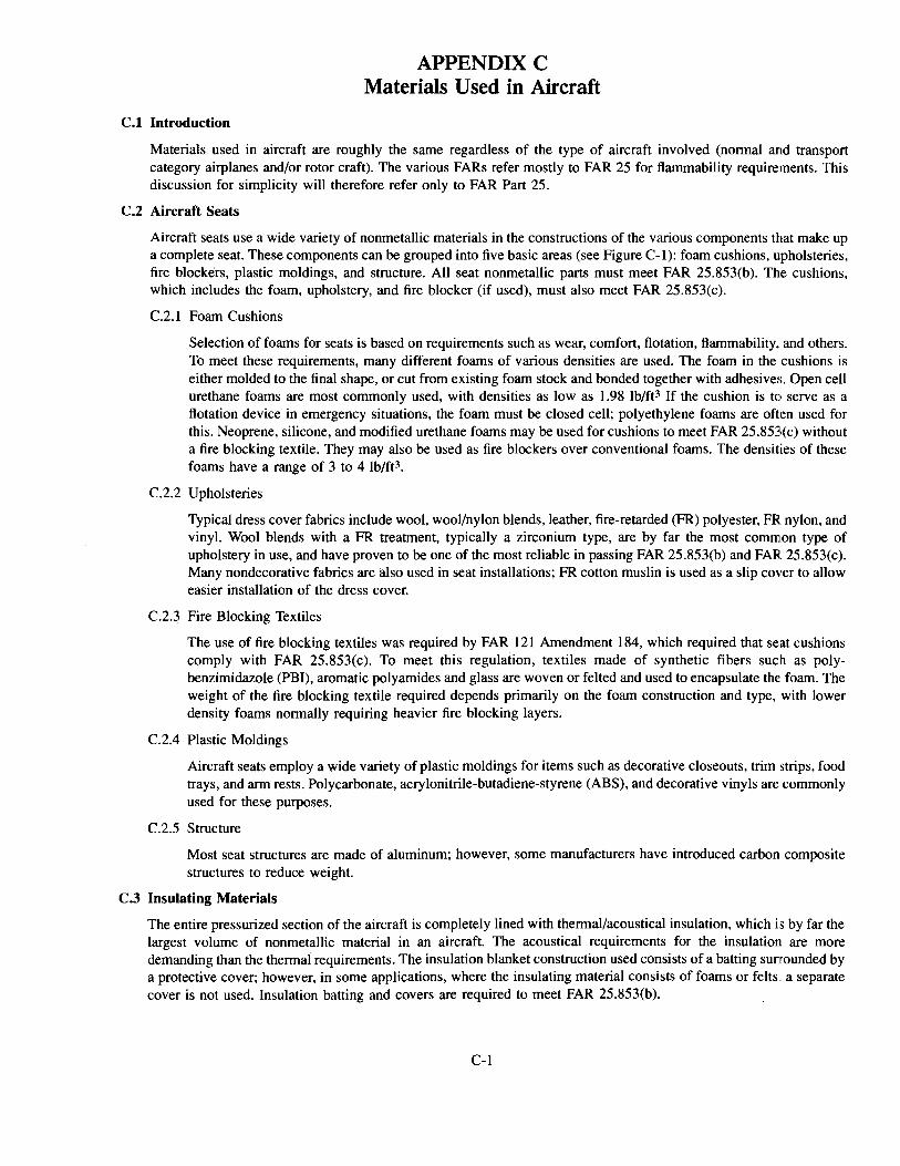
C.l Introduction
APPENDIX C Materials Used in Aircraft
Materials used in aircraft are roughly the same regardless of the type of aircraft involved (normal artd transport category airplanes and/or rotor craft). The various FARs refer mostly to FAR 25 for flammability requirements. This discussion for simplicity will therefore refer only to FAR Part 25.
C.2 Aircraft Seats
Aircraft seats use a wide variety of nonmetallic materials in the constructions of the various components that make up a complete seat. These components can be grouped into five basic areas (see Figure C-1): foam cushions, upholsteries, fire blockers, plastic moldings, and structure. All seat nonmetallic parts must meet FAR 25.853(b). The cushions, which includes the foam, upholstery, and fire blocker (if used), must also meet FAR 25.853(c).
C.2.1 Foam Cushions
Selection of foams for seats is based on requirements such as wear, comfort, flotation, flammability, and others. To meet these requirements, many different foams of various densities are used. The foam in the cushions is either molded to the final shape, or cut from existing foam stock and bonded together with adhesives. Open cell urethane foams are most commonly used, with densities as low as 1.98 lb/ft3 If the cushion is to serve as a flotation device in emergency situations, the foam must be closed cell; polyethylene foams are often used for this. Neoprene, silicone, and modified urethane foams may be used for cushions to meet FAR 25.85~o(c) without a fire blocking textile. They may also be used as fire blockers over conventional foams. The densities of these foams have a range of 3 to 4 lb/ft3.
C.2.2 Upholsteries
Typical dress cover fabrics include wool, wool/nylon blends, leather, fire-retarded (FR) polyester, FR nylon, and vinyl. Wool blends with a FR treatment, typically a zirconium type, are by far the most common type of upholstery in use, and have proven to be one of the most reliable in passing FAR 25.853(b) and FAR 25.853(c). Many nondecorative fabrics are also used in seat installations; FR cotton muslin is used as a slip cover to allow easier installation of the dress cover.
C.2.3 Fire Blocking Textiles
The use of fire blocking textiles was required by FAR 121 Amendment 184, which required that seat cushions comply with FAR 25.853(c). To meet this regulation, textiles made of synthetic fibers such as polybenzimidazole (PBI), aromatic polyamides and glass are woven or felted and used to encapsulate the foam. The weight of the fire blocking textile required depends primarily on the foam construction and type, with lower density foams normally requiring heavier fire blocking layers.
C.2.4 Plastic Moldings
Aircraft seats employ a wide variety of plastic moldings for items such as decorative closeouts, trim strips, food trays, and arm rests. Polycarbonate, acrylonitrile-butadiene-styrene (ABS), and decorative vinyls are commonly used for these purposes.
C.2.5 Structure
Most seat structures are made of aluminum; however, some manufacturers have introduced carbon composite structures to reduce weight.
C.3 Insulating Materials
The entire pressurized section of the aircraft is completely lined with thermal/acoustical insulation, which is by far the largest volume of nonmetallic material in an aircraft. The acoustical requirements for the insulation are more demanding than the thermal requirements. The insulation blanket construction used consists of a batting sunrounded by a protective cover; however, in some applications, where the insulating material consists of foams or felts .. a separate cover is not used. Insulation batting and covers are required to meet FAR 25.853(b).
C-1
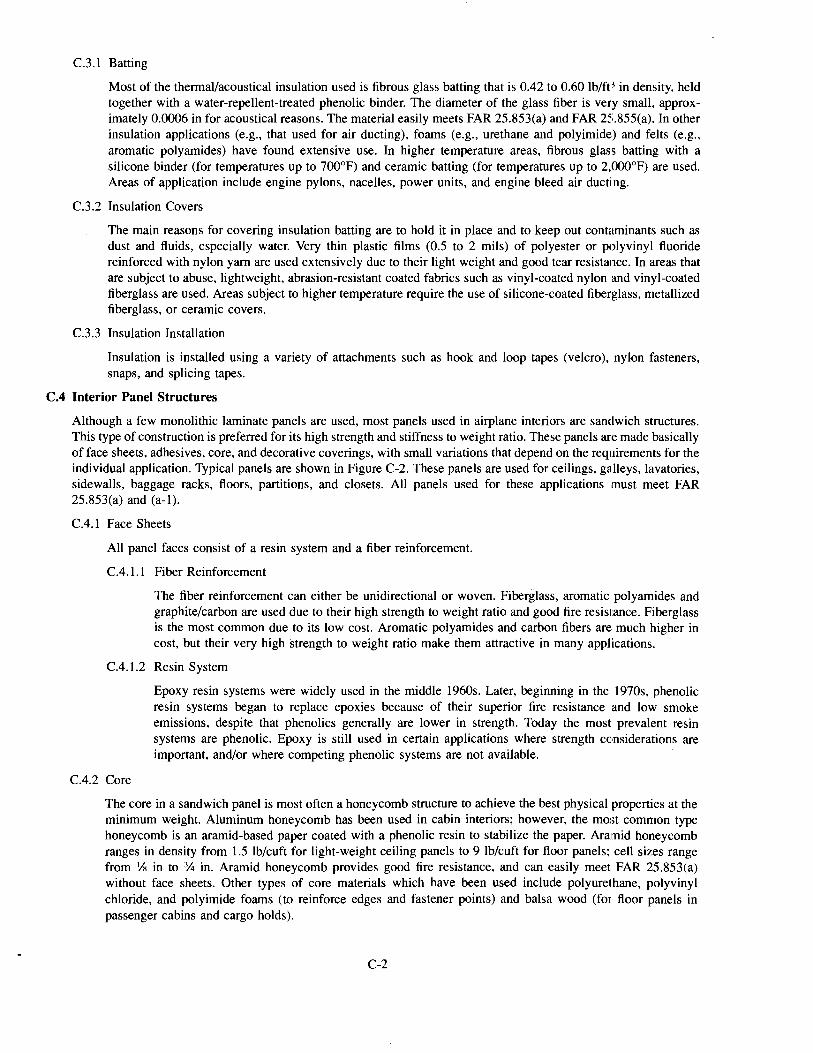
C.3.1 Batting
Most of the thermal/acoustical insulation used is fibrous glass batting that is 0.42 to 0.60 lb/ft3 in density, held together with a water-repellent-treated phenolic binder. The diameter of the glass fiber is very small, approximately 0.0006 in for acoustical reasons. The material easily meets FAR 25.853(a) and FAR 25.855(a). In other insulation applications (e.g., that used for air ducting), foams (e.g., urethane and polyimide) and felts (e.g., aromatic polyamides) have found extensive use. In higher temperature areas, fibrous glass batting with a silicone binder (for temperatures up to 700°F) and ceramic batting (for temperatures up to 2,000°F) are used. Areas of application include engine pylons, nacelles, power units, and engine bleed air ducting.
C.3.2 Insulation Covers
The main reasons for covering insulation batting are to hold it in place and to keep out contaminants such as dust and fluids, especially water. Very thin plastic films (0.5 to 2 mils) of polyester or polyvinyl fluoride reinforced with nylon yarn are used extensively due to their light weight and good tear resistance. In areas that are subject to abuse, lightweight, abrasion-resistant coated fabrics such as vinyl-coated nylon and vinyl-coated fiberglass are used. Areas subject to higher temperature require the use of silicone-coated fiberglass, metallized fiberglass, or ceramic covers.
C.3.3 Insulation Installation
Insulation is installed using a variety of attachments such as hook and loop tapes (velcro), nylon fasteners, snaps, and splicing tapes.
C.4 Interior Panel Structures
Although a few monolithic laminate panels are used, most panels used in airplane interiors are sandwich structures. This type of construction is preferred for its high strength and stiffness to weight ratio. These panels are made basically of face sheets, adhesives, core, and decorative coverings, with small variations that depend on the requirements for the individual application. Typical panels are shown in Figure C-2. These panels are used for ceilings, galleys, lavatories, sidewalls, baggage racks, floors, partitions, and closets. All panels used for these applications must meet FAR 25.853(a) and (a-1).
C.4.1 Face Sheets
All panel faces consist of a resin system and a fiber reinforcement.
C.4.1.1 Fiber Reinforcement
The fiber reinforcement can either be unidirectional or woven. Fiberglass, aromatic polyamides and graphite/carbon are used due to their high strength to weight ratio and good fire resistance. Fiberglass is the most common due to its low cost. Aromatic polyamides and carbon fibers are much higher in cost, but their very high strength to weight ratio make them attractive in many applications.
C.4.1.2 Resin System
C.4.2 Core
Epoxy resin systems were widely used in the middle 1960s. Later, beginning in the 1970s, phenolic resin systems began to replace epoxies because of their superior fire resistance and low smoke emissions, despite that phenolics generally are lower in strength. Today the most prevalent resin systems are phenolic. Epoxy is still used in certain applications where strength considerations are important, and/or where competing phenolic systems are not available.
The core in a sandwich panel is most often a honeycomb structure to achieve the best physical properties at the minimum weight. Aluminum honeycomb has been used in cabin interiors; however, the most common type honeycomb is an aramid-based paper coated with a phenolic resin to stabilize the paper. Aramid honeycomb ranges in density from 1.5 lb/cuft for light-weight ceiling panels to 9 lb/cuft for floor panels; cell sizes range from Ys in to % in. Aramid honeycomb provides good fire resistance, and can easily meet FAR 25.853(a) without face sheets. Other types of core materials which have been used include polyurethane, polyvinyl chloride, and polyimide foams (to reinforce edges and fastener points) and balsa wood (for floor panels in passenger cabins and cargo holds).
C-2
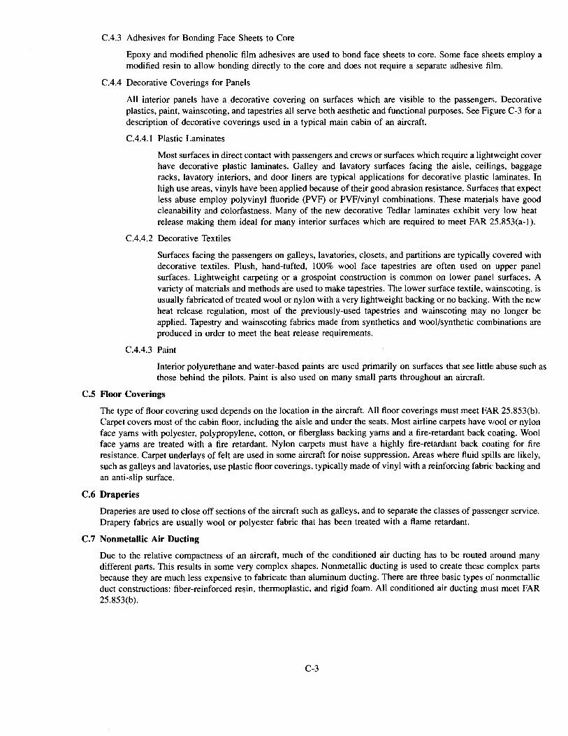
C.4.3 Adhesives for Bonding Face Sheets to Core
Epoxy and modified phenolic film adhesives are used to bond face sheets to core. Some face sheets employ a modified resin to allow bonding directly to the core and does not require a separate adhesive film.
C.4.4 Decorative Coverings for Panels
All interior panels have a. decorative covering on surfaces which are visible to the passengers. Decorative plastics, paint, wainscoting, and tapestries all serve both aesthetic and functional purposes. See Figure C-3 for a description of decorative coverings used in a typical main cabin of an aircraft.
C.4.4.1 Plastic Laminates
Most surfaces in direct contact with passengers and crews or surfaces which require a lightweight cover have decorative plastic laminates. Galley and lavatory surfaces facing the aisle, ceilings, baggage racks, lavatory interiors, and door liners are typical applications for decorative plastic laminates. In high use areas, vinyls have been applied because of their good abrasion resistance. Surfaces that expect less abuse employ polyvinyl fluoride (PVF) or PVF/vinyl combinations. These materials have good cleanability and colorfastness. Many of the new decorative Tedlar laminates exhibit very low heat release making them ideal for many interior surfaces which are required to meet FAR 25.853(a-l).
C.4.4.2 Decorative Textiles
Surfaces facing the passengers on galleys, lavatories, c~osets, and partitions are typically covered with decorative textiles. Plush, hand-tufted, 100% wool face tapestries are often used on upper panel surfaces. Lightweight carpeting or a grospoint construction is common on lower panel surfaces. A variety of materials and methods are used to make tapestries. The lower surface textile, wainscoting, is usually fabricated of treated wool or nylon with a very lightweight backing or no backing. With the new heat release regulation, most of the previously-used tapestries and wainscoting may no longer be applied. Tapestry and wainscoting fabrics made from synthetics and wool/synthetic combinations are produced in order to meet the heat release requirements.
C.4.4.3 Paint
Interior polyurethane and water-based paints are used primarily on surfaces that see littk abuse such as those behind the pilots. Paint is also used on many small parts throughout an aircraft.
C.S Floor Coverings
The type of floor covering used depends on the location in the aircraft. All floor coverings must meet FAR 25.853(b). Carpet covers most of the cabin floor, including the aisle and under the seats. Most airline carpets have wool or nylon face yams with polyester, polypropylene, cotton, or fiberglass backing yams and a fire-retardant back coating. Wool face yams are treated with a fire retardant. Nylon carpets must have a highly fire-retardant back coating for fire resistance. Carpet underlays of felt are used in some aircraft for noise suppression. Areas where fluid spills are likely, such as galleys and lavatories, use plastic floor coverings, typically made of vinyl with a reinforcing fabric: backing and an anti-slip surface.
C.6 Draperies
Draperies are used to close off sections of the aircraft such as galleys, and to separate the classes of passenger service. Drapery fabrics are usually wool or polyester fabric that has been treated with a flame retardant.
C. 7 Nonmetallic Air Ducting
Due to the relative compactness of an aircraft, much of the conditioned air ducting has to be routed around many different parts. This results in some very complex shapes. Nonmetallic ducting is used to create these complex parts because they are much less expensive to fabricate than aluminum ducting. There are three basic types of nonmetallic duct constructions: fiber-reinforced resin, thermoplastic, and rigid foam. All conditioned air ducting must meet FAR 25.853(b).
C-3
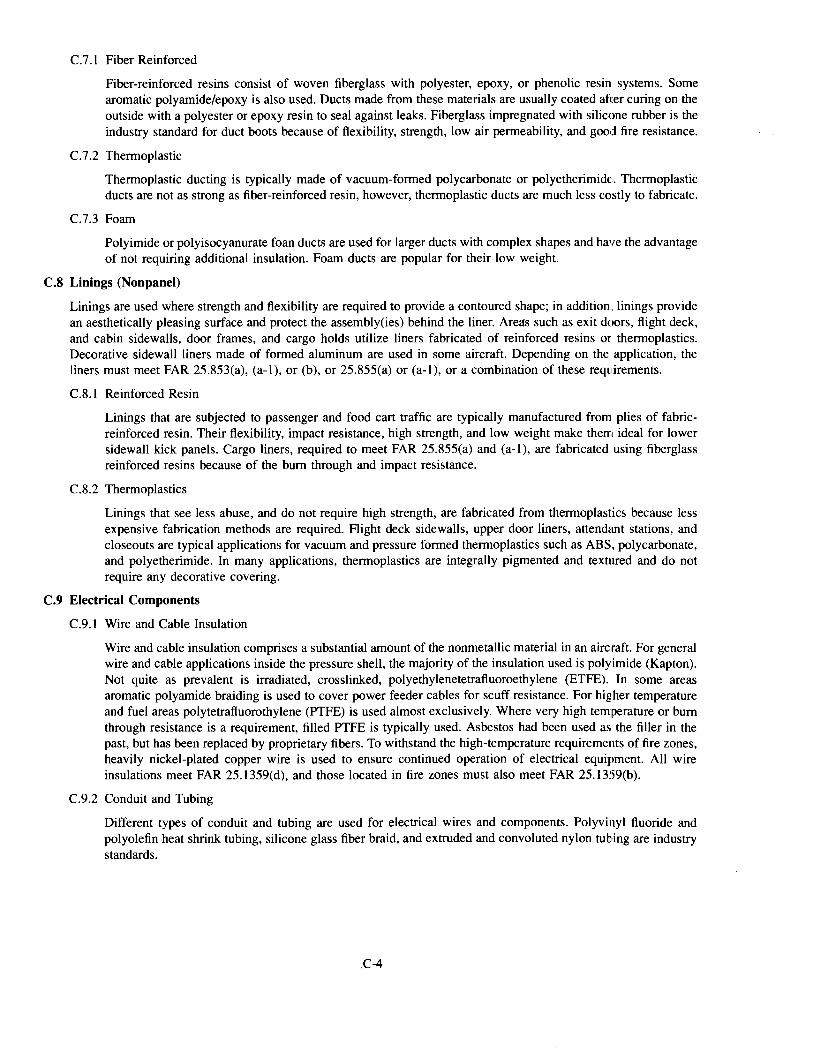
C.7.1 Fiber Reinforced
Fiber-reinforced resins consist of woven fiberglass with polyester, epoxy, or phenolic resin systems. Some aromatic polyamide/epoxy is also used. Ducts made from these materials are usually coated after curing on the outside with a polyester or epoxy resin to seal against leaks. Fiberglass impregnated with silicone rubber is the industry standard for duct boots because of flexibility, strength, low air permeability, and good fire resistance.
C.7.2 Thermoplastic
Thermoplastic ducting is typically made of vacuum-formed polycarbonate or polyetherimide:. Thermoplastic ducts are not as strong as fiber-reinforced resin, however, thermoplastic ducts are much less costly to fabricate.
C.7.3 Foam
Polyimide or polyisocyanurate foan ducts are used for larger ducts with complex shapes and have the advantage of not requiring additional insulation. Foam ducts are popular for their low weight.
C.8 Linings (Nonpanel)
Linings are used where strength and flexibility are required to provide a contoured shape; in addition., linings provide an aesthetically pleasing surface and protect the assembly(ies) behind the liner. Areas such as exit doors, flight deck, and cabin sidewalls, door frames, and cargo holds utilize liners fabricated of reinforced resins or thermoplastics. Decorative sidewall liners made of formed aluminum are used in some aircraft. Depending on the application, the liners must meet FAR 25.853(a), (a-1), or (b), or 25.855(a) or (a-1), or a combination of these requirements.
C.8.1 Reinforced Resin
Linings that are subjected to passenger and food cart traffic are typically manufactured from plies of fabricreinforced resin. Their flexibility, impact resistance, high strength, and low weight make them ideal for lower sidewall kick panels. Cargo liners, required to meet FAR 25.855(a) and (a-1), are fabricated using fiberglass reinforced resins because of the bum through and impact resistance.
C.8.2 Thermoplastics
Linings that see less abuse, and do not require high strength, are fabricated from thermoplastics because less expensive fabrication methods are required. ·Flight deck sidewalls, upper door liners, attend<mt stations, and closeouts are typical applications for vacuum and pressure formed thermoplastics such as ABS, polycarbonate, and polyetherimide. In many applications, thermoplastics are integrally pigmented and textured and do not require any decorative covering.
C.9 Electrical Components
C.9.1 Wire and Cable Insulation
Wire and cable insulation comprises a substantial amount of the nonmetallic material in an aircraft. For general wire and cable applications inside the pressure shell, the majority of the insulation used is polyimide (Kapton). Not quite as prevalent is irradiated, crosslinked, polyethylenetetrafluoroethylene (ETFE). In some areas aromatic polyamide braiding is used to cover power feeder cables for scuff resistance. For higher temperature and fuel areas polytetrafluorothylene (PTFE) is used almost exclusively. Where very high temperature or bum through resistance is a requirement, filled PTFE is typically used. Asbestos had been used as the filler in the past, but has been replaced by proprietary fibers. To withstand the high-temperature requirements of fire zones, heavily nickel-plated copper wire is used to ensure continued operation of electrical equipment. All wire insulations meet FAR 25.1359(d), and those located in fire zones must also meet FAR 25.1359(b).
C.9.2 Conduit and Tubing
Different types of conduit and tubing are used for electrical wires and components. Polyvinyl fluoride and polyolefin heat shrink tubing, silicone glass fiber braid, and extruded and convoluted nylon tubing are industry standards.
.C-4
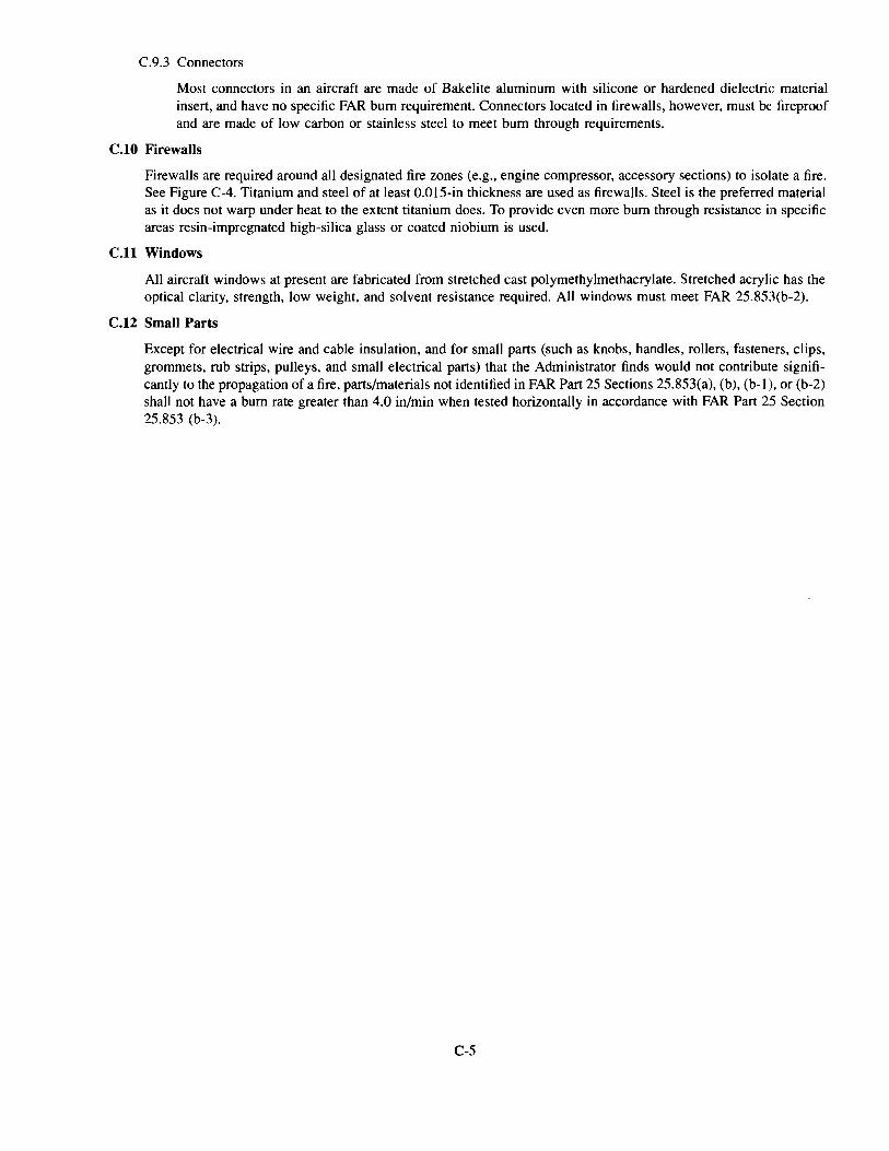
C.9.3 Connectors
Most connectors in an aircraft are made of Bakelite aluminum with silicone or hardened dielectric material insert, and have no specific FAR bum requirement. Connectors located in firewalls, however, must be fireproof and are made of low carbon or stainless steel to meet bum through requirements.
C.lO Firewalls
Firewalls are required around all designated fire zones (e.g., engine compressor, accessory sections) to isolate a fire. See Figure C-4. Titanium and steel of at least 0.015-in thickness are used as firewalls. Steel is the preferred material as it does not warp under heat to the extent titanium does. To provide even more bum through resistance in specific areas resin-impregnated high-silica glass or coated niobium is used.
C.ll Windows
All aircraft windows at present are fabricated from stretched cast polymethylmethacrylate. Stretched acrylic has the optical clarity, strength, low weight, and solvent resistance required. All windows must meet FAR 25.853(b-2).
C.12 Small Parts
Except for electrical wire and cable insulation, and for small parts (such as knobs, handles, rollers, fasteners, clips, grommets, rub strips, pulleys, and small electrical parts) that the Administrator finds would not contribute significantly to the propagation of a fire, parts/materials not identified in FAR Part 25 Sections 25.853(a), (b), (b-1 ), or (b-2) shall not have a bum rate greater than 4.0 in/min when tested horizontally in accordance with FAR Part 2:5 Section 25.853 (b-3).
C-5
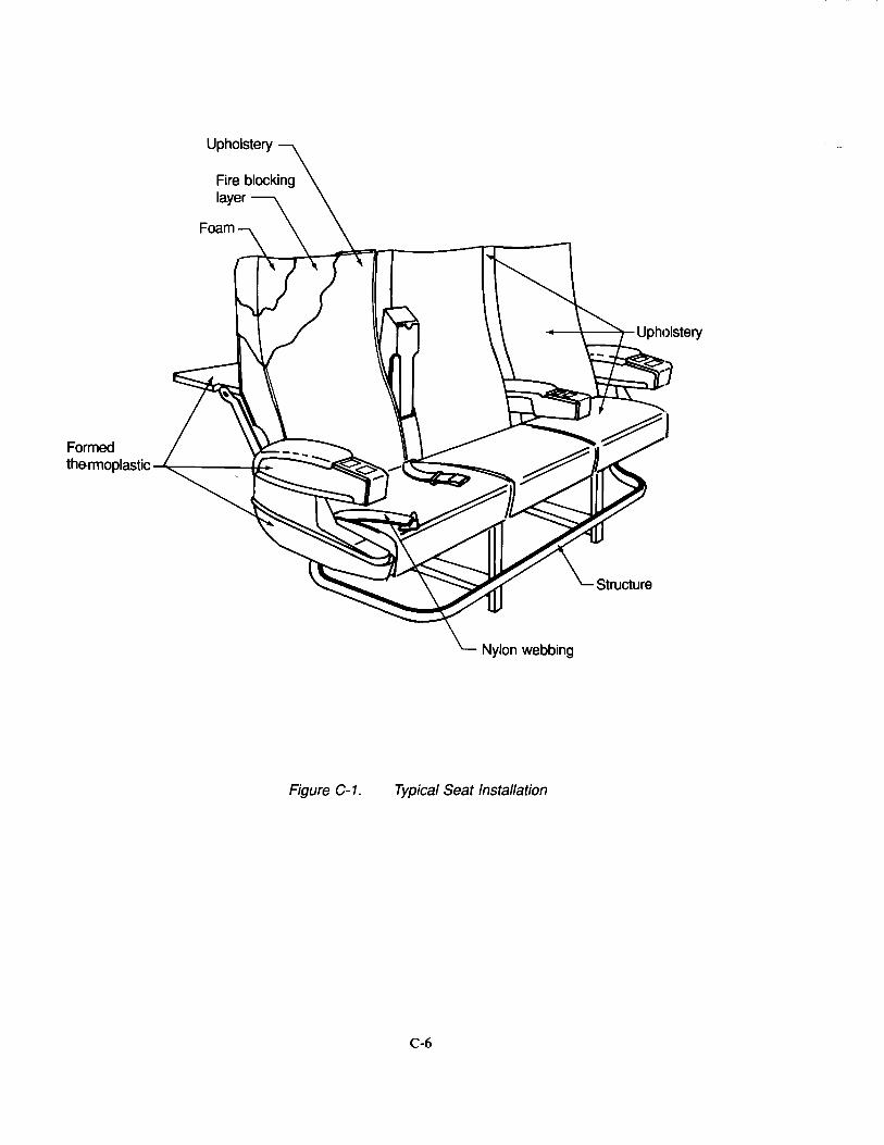
Formed the-rmoplastic .....t..::-------1~-r+-
Figure C-1. Typical Seat Installation
C-6
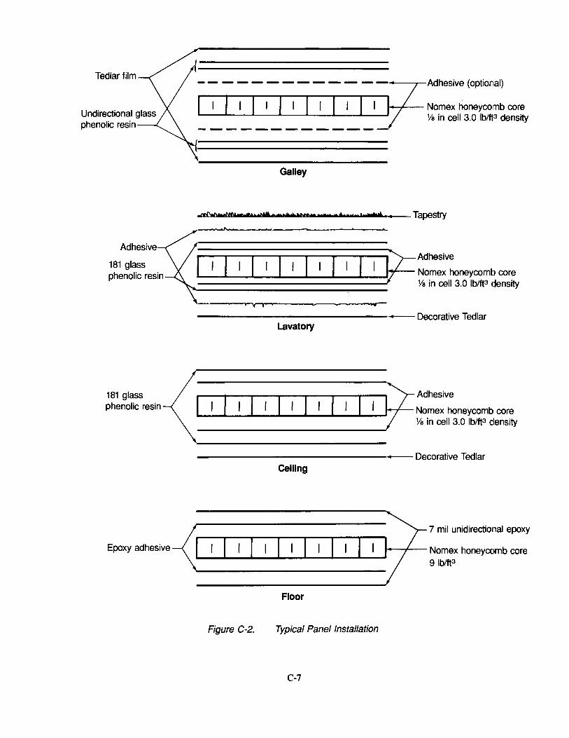
Tedlar film
Adhesive
181 glass phenolic resin
181 glass phenolic resin
-- - - - -- -- -- -- - - - ~-~-Adhesive (optional)
I I I I I I I I I I I I I </ Nomex honeycomb core - - - - - Ys in cell 3.0 lblfP density --------------
Galley
~ ........... ,MttM"t "$ •• ,,I I •••• Tapestry
~------------------~
~~Adhesive I r Nomex honeycomb core
~~=~=~=~=~~=~=~=~ Ys in cell 3.0 lblft3 density
-----------------Decorative Tedlar Lavatory
------------------Decorative Tedlar Ceiling
Floor
Figure C-2. Typical Panel Installation
C-7

Main Cabin
<D Panel construction with tapestry cover. ® Panel construction with wainscot cover. ® Panel construction with decorative plastic laminate. ® Formed thermoplastic or laminate. ®Formed aluminum with decorative plastic laminate. ® Composite laminate with wainscot cover. \lJ Panel construction with carpet cover.
Figure C-3. Typical Main Cabin
C-8
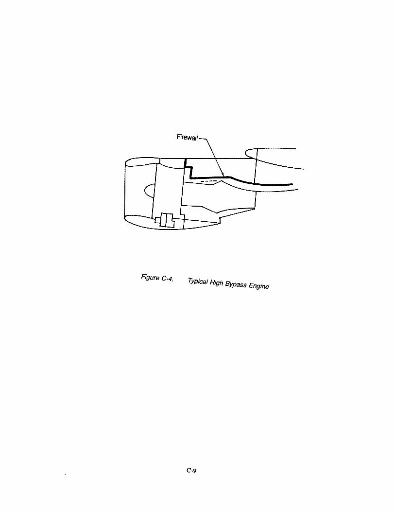
Firewall
Figure C-4. Typical High Bypass Engine
C-9
This page intentionally left blank
C-10
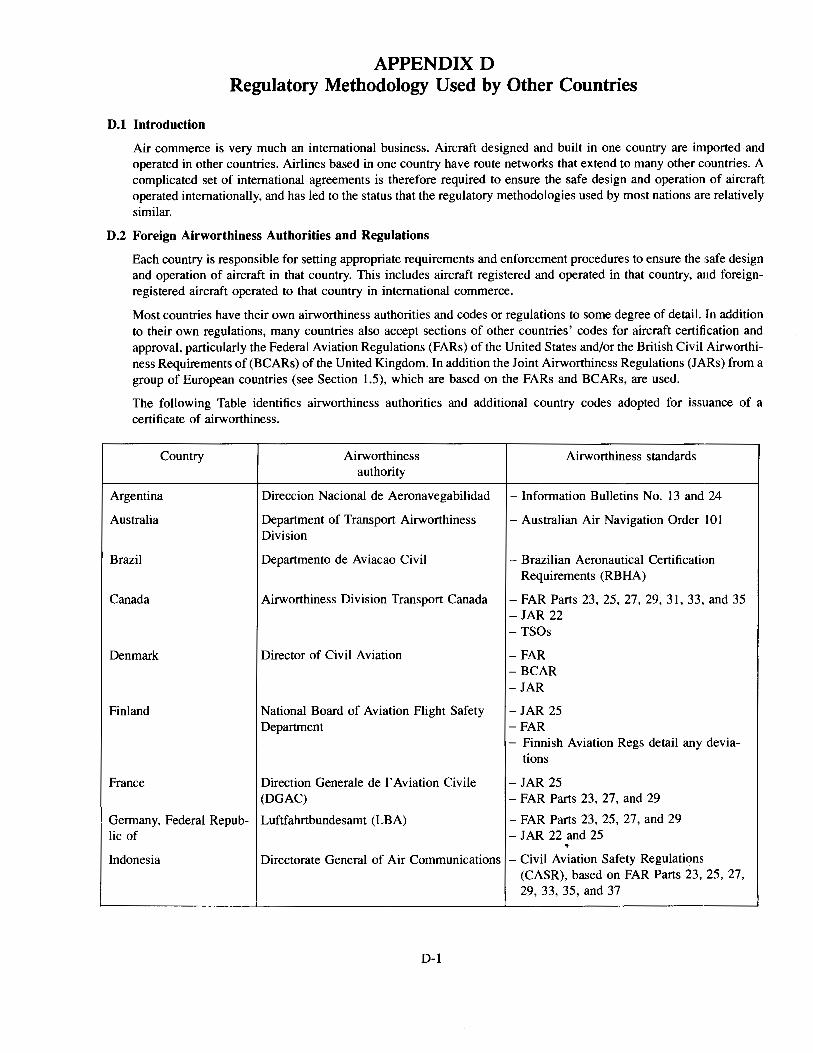
APPENDIX D Regulatory Methodology Used by Other Countries
D.l Introduction
Air commerce is very much an international business. Aircraft designed and built in one country are imported and operated in other countries. Airlines based in one country have route networks that extend to many other countries. A complicated set of international agreements is therefore required to ensure the safe design and operation of aircraft operated internationally, and has led to the status that the regulatory methodologies used by most nations are relatively similar.
D.2 Foreign Airworthiness Authorities and Regulations
Each country is responsible for setting appropriate requirements and enforcement procedures to ensure the safe design and operation of aircraft in that country. This includes aircraft registered and operated in that country, and foreignregistered aircraft operated to that country in international commerce.
Most countries have their own airworthiness authorities and codes or regulations to some degree of detail. In addition to their own regulations, many countries also accept sections of other countries' codes for aircraft certification and approval, particularly the Federal Aviation Regulations (FARs) of the United States and/or the British Civil Airworthiness Requirements of (BCARs) of the United Kingdom. In addition the Joint Airworthiness Regulations (JARs) from a group of European countries (see Section 1.5), which are based on the FARs and BCARs, are used.
The following Table identifies airworthiness authorities and additional country codes adopted for issuance of a certificate of airworthiness.
Country
Argentina
Australia
Brazil
Canada
Denmark
Finland
France
Airworthiness Airworthiness standards authority
Direccion Nacional de Aeronavegabilidad -Information Bulletins No. 13 and 24
Department of Transport Airworthiness -Australian Air Navigation Order 101 Division
Departmento de Aviacao Civil - Brazilian Aeronautical Certification Requirements (RBHA)
Airworthiness Division Transport Canada -FAR Parts 23, 25, 27, 29, 31, 33, and 35 -JAR 22
Director of Civil Aviation
National Board of Aviation Flight Safety Department
Direction Generale de I' Aviation Civile (DGAC)
-TSOs
-FAR -BCAR -JAR
-JAR 25 -FAR - Finnish Aviation Regs detail any devia-
tions
-JAR 25 - FAR Parts 23, 27, and 29
Germany, Federal Repub- Luftfahrtbundesamt (LBA) lie of
- FAR Parts 23, 25, 27, and 29 -JAR 22 and 25
Indonesia Directorate General of Air Communications - Civil Aviation Safety Regulations (CASR), based on FAR Parts 23, 25, 27, 29, 33, 35, and 37
D-1
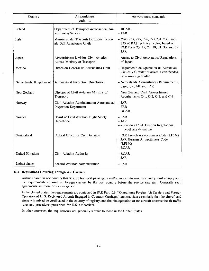
Country Airworthiness Airworthiness standards authority
Ireland Department of Transport Aeronautical Air- -BCAR worthiness Service -FAR
Italy Ministereo dei Trasporti Direzione Gener- -Parts 223, 225, 226, 228 231, 233, and ale Dell'Aviazionne Civile 235 of RAI Technical Rules, based on
FAR Parts 23, 25, 27, 29, 31, 33, and 35 -JAR
Japan Airworthiness Division Civil Aviation - Annex to Civil Aeronautics Regulations Bureau Ministry of Transport of Japan
Mexico Direccion General de Aeronautica Civil - Reglamento de Operacion de Aeronaves Civiles y Circular relativos a certificados de aeronavegabilidad
Netherlands, Kingdom of Aeronautical Inspection Directorate - Netherlands Airworthiness Requirements, based on JAR and FAR
New Zealand Director of Civil Aviation Ministry of - New Zealand Civil Airworthiness Transport Requirements C-1, C-2, C-3, and C-4
Norway Civil Aviation Administration Aeronautical -JAR Inspection Department -FAR
-BCAR
SwedeQ Board of Civil Aviation Flight Safety -FAR Department -JAR
.,... - Swedish Civil Aviation Regulations detail any deviations
Switzerland Federal Office for Civil Aviation - FAR French Airworthiness Code (LFSM) -JAR German Airworthiness Code
(LFSM) -BCAR
United Kingdom Civil Aviation Authority -BCAR -JAR
United States Federal Aviation Administration -FAR
D.3 Regulations Covering Foreign Air Carriers
Airlines based in one country that wish to transport passengers and/or goods into another country must comply with the requirements imposed on foreign carriers by the host country before the service can start. Generally such agreements are more or less reciprocal.
In the United States, the requirements are contained in FAR Part 129, "Operations: Foreign Air CaJTiers and Foreign Operators of U. S. Registered Aircraft Engaged in Common CaJTiage," and mandate essentially that the aircraft and aircrew involved be certificated in the country of registry, and that the operation of the aircraft observe the air traffic rules and procedures prescribed for U.S. air carriers.
In other countries, the requirements are generally similar to those in the United States.
D-2
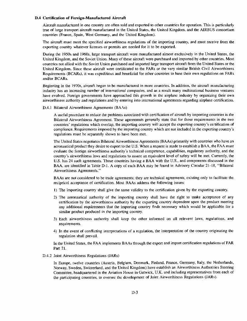
D.4 Certification of Foreign-Manufactured Aircraft
Aircraft manufactured in one country are often sold and exported to other countries for operation. This is particularly true of large transport aircraft manufactured in the United States, the United Kingdom, and the AIRBUS consortium countries (France, Spain, West Germany, and the United Kingdom).
The aircraft must meet the specified airworthiness regulations of the importing country, and must receive from the exporting country whatever licenses or permits are needed for it to be exported.
During the 1950s and 1960s, large transport aircraft were manufactured almost exclusively in the United States, the United Kingdom, and the Soviet Union. Many of these aircraft were purchased and imported by other countries. Most countries not allied with the Soviet Union purchased and imported large transport aircraft from the United States or the United Kingdom. Since these aircraft were certificated to the FARs or the very similar British Civil Airworthiness Requirements (BCARs), it was expeditious and beneficial for other countries to base their own regulations on FARs and/or BCARs.
Beginning in the 1970s, aircraft began to be manufactured in more countries. In addition, the aircraft manufacturing industry has an increasing number of international companies, and as a result many multinational business ventures have evolved. Foreign governments have approached this growth in the airplane industry by organizing their own airworthiness authority and regulations and by entering into international agreements regarding airplane certification.
D.4.1 Bilateral Airworthiness Agreements (BAAs)
A useful procedure to reduce the problems associated with certification of aircraft by importing countries is the Bilateral Airworthiness Agreement. These agreements generally state that for those requirements in the two countries' regulations which overlap, the importing country will accept the exporting country's certification of compliance. Requirements imposed by the importing country which are not included in the exporting country's regulations must be separately shown to have been met.
The United States negotiates Bilateral Airworthiness Agreements (BAAs) primarily with countries who have an aeronautical product they desire to export to the U.S. When a request is made to establish a BAA, the FAA must evaluate the foreign airworthiness authority's technical competence, capabilities, regulatory authority, and the country's airworthiness laws and regulations to assure an equivalent level of safety will be met. Currently, the U.S. has 24 such agreements. Those countries having a BAA with the U.S., and components discussed in the BAA, are identified in Table D-1. A copy of each BAA may be found in Advisory Circular 21-18, "Bilateral Airworthiness Agreements."
BAAs are not considered to be trade agreements; they are technical agreements, existing only to facilitate the recipricol acceptance of certification. Most BAAs address the following issues:
1) The importing country shall give the same validity to the certification given by the exporting country.
2) The aeronautical authority of the importing country shall have the right to make acceptance of any certification by the airworthiness authority by the exporting country dependent upon the product meeting any additional requirements that the importing country finds necessary which would be applicable for a similar product produced in the importing country.
3) Each airworthiness authority shall keep the other informed on all relevent laws, regulations, and requirements.
4) In the event of conflicting interpretations of a regulation, the interpretation of the country originating the regulation shall prevail.
In the United States, the FAA implements BAAs through the export and import certification regulations of FAR Part 21.
D.4.2 Joint Airworthiness Regulations (JARs)
In Europe, twelve countries (Austria, Belgium, Denmark, Finland, France, Germany, Italy, the Netherlands, Norway, Sweden, Switzerland, and the United Kingdom) have establish an Airworthiness Authorities Steering Committee, headquartered in the Aviation House in Gatwick, U.K. and including representatives from each of the participating countries, to oversee the development of Joint Airworthiness Regulations (JARs).
D-3

The goal of the JARs is to establish common airworthiness requirements and certification procedures within Europe in order to facilitate airplane and airplane part certification. A long-term goal is to eventually seek common regulations with the United States Federal Aviation Administration wherever possible.
The first JAR covered aircraft engines, and was established in 1972. Other JARs have followed. Most of the JARs are based in part or in toto on FARs or BCARs.
In 1979 a milestone was passed when JAR 25, which was based on FAR 25 and covered large transport aircraft, was adopted. France, the Netherlands, the United Kingdom, and West Germany have adopted JAR 25 as their sole, common code for certification of large transport aircraft. Incidentally, FAR 25 Amendments are not automatically adopted into JAR 25; they must first be accepted by the Steering Committee before incorporation.
D-4

Table 0-1. Summary of Bilateral Airworthiness Agreements
Revised 2/1 /82 Components (/) (/) (/) (/) t:: - t:: t:: ..... co co(/) co co 0. o.Q) 0. 0. C:::' c:::c::: c::: c::: 0 o·- 0 .Q (/) +:: ·- O'l ·.;:; rJ) co -c::: -Q)
BQ) co ..... Bu u .g~ ;;:::.;:: ;;:::.;:: ;;:::C::: ·-co :0~ ·- Q) ·-co
Bilateral countries -a.._ "Oa. "0·-ou o-(/) Ou 00 E§: E-= Q) E.: E ..... (/) ';:.CO c::: ';:.CO ';:::,0. ';:.CO -~ C:::-o ·a, C:::-o C:::-o C:::-o ::0 O>Q) c::: Q)Q)
(/) O>Q) (/) O>Q) E Et:: Q) Et:: Et:: Q) Et:: ..... u Q) .;:: 0>0 .;:: 0>0 ~ 0>0 c::: 0>0 (ij uo. uo. uo. uo. (/)
co co Q) co ·;:: (/) ..... COX ..... cox cox cox Q) (/) co c_O> u Q.O> 0. Q.O> a. Q.O> u 0 - t::: .0 ..... Q)'"- ..... 0>'"- 0>'"- 0. 0>'"- co co :::1
~ ~ ..... a:.E a:.E a.. a:.E <( a:.E ~ a.. en
Australia (ref. notes 4 and 7) X X X X X X X X x2 x2 x2 Austria X X X X X X
Belgium (ref. note 4) X X X X X X X X x2 x2 x2 Brazil (ref. note 4) X X X X X X X X x2 x2 x2 Canada X X X X X X X X X X a X a
Czechoslovakia X X X X X X X X
Denmark X X X X X X X X x2 x2 x2 Finland x1 x1 Xs Xs
France (ref. note 4) X X X X X X X X x2 x2 x2 Germany (ref. note 4) X X X X X X X X x2 x2 x2 Israel X X X X X X X X x2 x2 x2 Italy (ref. note 4) X X X X X X X X x2 x2 x2 Japan (ref. note 4) X X X X X X X X x2 x2 x2 Netherlands (ref. note 4) X X X X X X X X x2 x2 x2 New Zealand x3 x3 x3 x3 x3 x3 x3 x3 x2 x2 x2 Norway X X X X
Poland Xs Xs Xs Xs Xs Xs Xs Xs x2 x2 x2 Romania x1 x1 Singapore (ref. note 4) Xs Xs Xs Xs Xs Xs Xs Xs x2 x2 x2 South Africa X X
Spain X X X X
Sweden (ref. note 4) X X X X X X X X x2 x2 Xz
Switzerland (ref. note 4) X X X X X X X X x2 x2 x2 United Kingdom (ref. note 4) X X X X X X X X x2 x2 x2
D-5
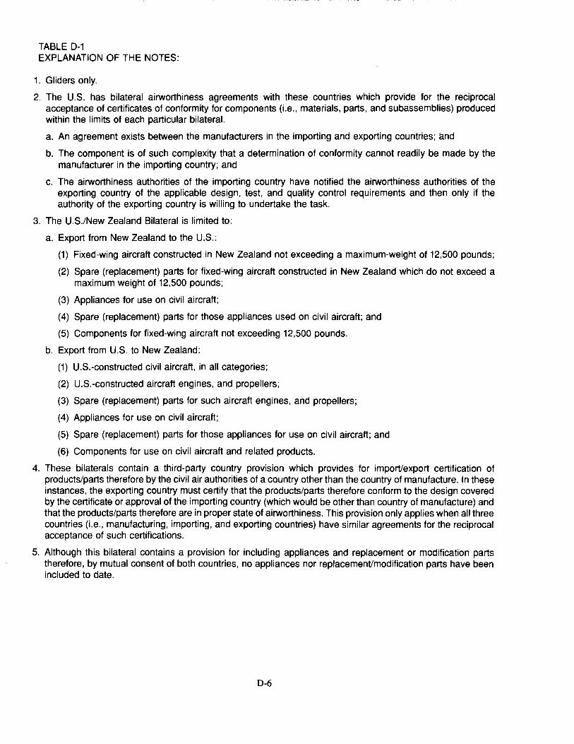
TABLE D-1 EXPLANATION OF THE NOTES:
1. Gliders only.
2. The U.S. has bilateral airworthiness agreements with these countries which provide for the reciprocal acceptance of certificates of conformity for components (i.e., materials, parts, and subassemblies) produced within the limits of each particular bilateral.
a. An agreement exists between the manufacturers in the importing and exporting countries; and
b. The component is of $UCh complexity that a determination of conformity cannot readily be made by the manufacturer in the importing country; and
c. The airworthiness authorities of the importing country have notified the airworthiness authorities of the exporting country of the applicable design, test, and quality control requirements and then only if the authority of the exporting country is willing to undertake the task.
3. The U.S./New Zealand Bilateral is limited to:
a. Export from New Zealand to the U.S.:
(1) Fixed-wing aircraft constructed in New Zealand not exceeding a maximum-weight of ·12,500 pounds;
(2) Spare (replacement) parts for fixed-wing aircraft constructed in New Zealand which do not exceed a maximum weight of 12,500 pounds;
(3) Appliances for use on civil aircraft;
(4) Spare (replacement) parts for those appliances used on civil aircraft; and
(5) Components for fixed-wing aircraft not exceeding 12,500 pounds.
b. Export from U.S. to New Zealand:
(1) U.S.-constructed civil aircraft, in all categories;
(2) U.S.-constructed aircraft engines, and propellers;
(3) Spare (replacement) parts for such aircraft engines, and propellers;
(4) Appliances for use on civil aircraft;
(5) Spare (replacement) parts for those appliances for use on civil aircraft; and
(6) Components for use on civil aircraft and related products.
4. These bilaterals contain a third-party country provision which provides for import/export certification of products/parts therefore by the civil air authorities of a country other than the country of manufacture. In these instances, the exporting country must certify that the products/parts therefore conform to the design covered by the certificate or approval of the importing country (which would be other than country of manufacture) and that the products/parts therefore are in proper state of airworthiness. This provision only applies when all three countries (i.e., manufacturing, importing, and exporting countries) have similar agreements for the reciprocal acceptance of such certifications.
5. Although this bilateral contains a provision for including appliances and replacement or modification parts therefore, by mutual consent of both countries, no appliances nor replacement/modification parts have been included to date.
D-6
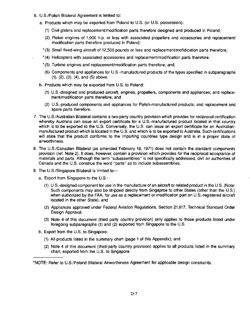
6. U.S./Polish Bilateral Agreement is limited to:
a. Products which may be exported from Poland to U.S. (or U.S. possession):
(1) Civil gliders and replacement/modification parts therefore designed and produced in Poland;
(2) Piston engines of 1,000 h.p. or less with associated propellers and accessories and replacement/ modification parts therefore produced in Poland;
* (3) Small fixed-wing aircraft of 12,500 pounds or less and replacement/mofidication parts therefore;
* (4) Helicopters with associatep accessories and replacement/modification parts therefore;
* (5) Turbine engines and replacement/modification parts therefore; and,
(6) Components and appliances for U.S.-manufactured products of the types specified in subparagraphs (1), (2), (3), (4), and (5) above.
b. Products which may be exported from U.S. to Poland:
(1) U.S.-designed and produced aircraft, engines, propellers, components and appliances; and replace-ment/modification parts therefore; and ·
(2) U.S.-produced components and appliances for Polish-manufactured products; and replact:~ment and spare parts therefore.
7. The U.S./ Australian Bilateral contains a two-party country provision which provides for reciprocal certification whereby Australia can issue an export certificate for a U.S.-manufactured product located in that country which is to be exported to the U.S. Conversely, the U.S. can issue an export certificate for an Australianmanufactured product which is located in the U.S. and which is to be exported to Australia. Such certifications will state that the product conforms to the importing countries type design and is in a propm state of airworthiness.
8. The U.S./Canadian Bilateral (as amended February 18, 1971) does not contain the standard components provision (ref. Note 2). It does, however, contain a provision which provides for the reciprocal acct:~ptance of materials and parts. Although the term "subassemblies" is not specifically addressed, civil air authorities of Canada and the U.S. construe the word "parts" as to include subassemblies.
9 .. The U.S./Singapore Bilateral is limited to-
a. Export from Singapore to the U.S.:
(1) U.S.-designed component for use in the manufacture of an aircraft or related product in the U.S. (Note: Such components may also be shipped directly from Singaproe to other States (other than the U.S.) when authorized by the FAA, for use as a replacement or modification part on U.S.-registered aircraft located in the other State); and
(2) Appliances approved under Federal Aviation Regulations, Section 21.617, Technical Standard Order Design Approval.
(3) Note 4 of this document (third party country provision) only applies to those products listed under foregoing subparagraphs (1) and (2) exported from Singapore to the U.S.
b. Export from the U.S. to Singapore:
(1) All products listed in the summary chart (page 1 of this Appendix); and
(2) Note 4 of this document (third-party country provision) applies to all products listed in the summary chart, exported from the U.S. to Singapore.
*NOTE: Refer to U.S./Poland Bilateral Airworthiness Agreement for applicable design constraints.
D-7

This page intentionally left blank
D-8
APPENDIX E Aircraft Industries Internal Test Methods and Guidelines
As written, FAA test procedures for meeting the requirements set forth in Part 25 sometimes contain incomplete documentation (e.g., the firewall test). In order to establish standardized guidelines for these test procedun!s, including more detailed instructions and safety precautions, individual aircraft manufacturers have established some of their own internal documentation. This documentation, as well as having detailed instructions, is at times also used to certify the different materials to the applicable Federal Aviation Regulation (FAR). Table E-1 contains a listing of each FAR fire test and the equivalent company internal test method document number as well as the applicable ASTM standard, if any. Other testing related to fire safety is also listed (such as toxicity). These documents are normally available from the listed company.
E-1
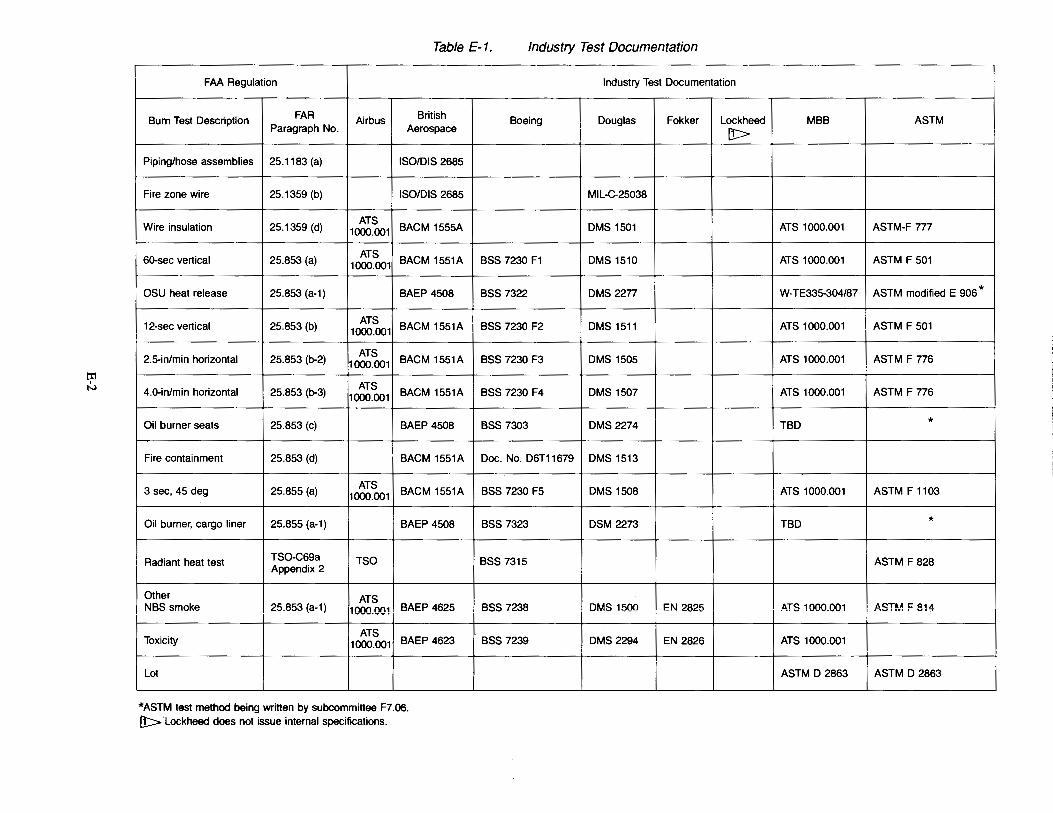
ti1 I
N
Table E-1. Industry Test Documentation
FAA Regulation
Burn Test Description FAR Airbus British Paragraph No. Aerospace
Piping/hose assemblies 25.1183 (a) ISO/DIS 2685
Fire zone wire 25.1359 (b) !SO/DIS 2685
Wire insulation 25.1359 (d) ATS
BACM 1555A 1000.001
60-sec vertical 25.853 (a) ATS
BACM 1551A 1000.001
OSU heat release 25.853 (a-1) BAEP 4508
12-sec vertical 25.853 (b) ATS
BACM 1551A 1000.001
2.5-in/min horizontal 25.853 (b-2) ATS
BACM 1551A 1000.001
4.0-in/min horizontal 25.853 (b-3) ATS
BACM 1551A 1000.001
Oil burner seats 25.853 (c) BAEP 4508
Fire containment 25.853 (d) BACM 1551A
3 sec, 45 deg 25.855 (a) ATS
BACM 1551A 1000.001
Oil burner, cargo liner 25.855 (a-1) BAEP 4508
Radiant heat test TSO-C69a TSO Appendix 2
Other ATS NBS smoke 25.853 (a-1) 1000.001 BAEP 4625
Toxicity ATS
BAEP 4623 1000.001
Lot
'"ASTM test method being written by subcommittee F7.06. [!:> Lockheed does not issue internal specifications.
Industry Test Documentation
Boeing Douglas Fokker Lockheed [!>
MIL-C-25038
OMS 1501
BSS 7230 F1 OMS 1510
BSS 7322 OMS 2277
BSS 7230 F2 OMS 1511
BSS 7230 F3 OMS 1505
BSS 7230 F4 OMS 1507
BSS 7303 OMS 2274
Doc. No. D6T11679 OMS 1513
BSS 7230 F5 OMS 1508
BSS 7323 DSM 2273
BSS 7315
BSS 7238 OMS 1500 EN 2825
BSS 7239 DMS2294 EN 2826
I
MBB ASTM I
ATS 1000.001 ASTM-F 777
ATS 1000.001 ASTM F 501
W-TE335-304/87 ASTM modified E 906 *
ATS 1000.001 ASTM F 501
ATS 1000.001 ASTM F 776
ATS 1000.001 ASTM F 776
TBD *
ATS 1000.001 ASTM F 1103
TBD *
ASTM F 828
~:rs 1000.001 AST~.~ F 814
ATS 1000.001
ASTM D 2863 ASTM D 2863
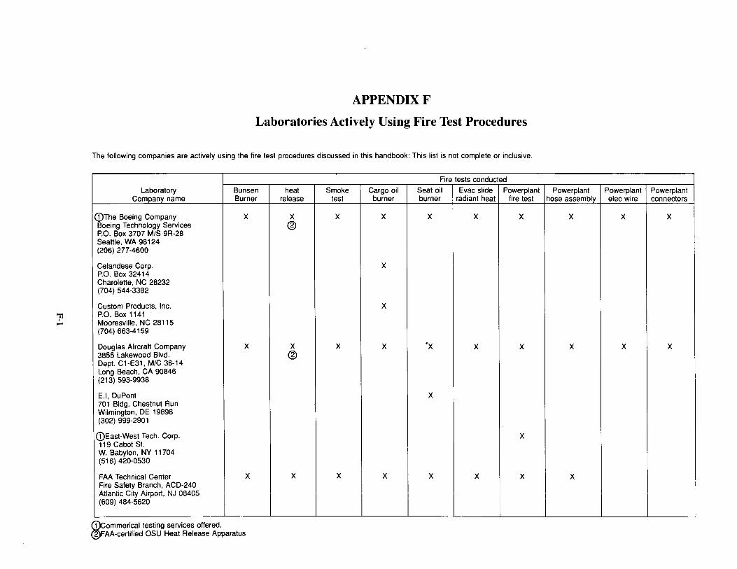
71 ....
APPENDIXF
Laboratories Actively Using Fire Test Procedures
The following companies are actively using the fire test procedures discussed in this handbook: This list is not complete or inclusive.
Fire tests conducted
Laboratory Bunsen heat Smoke Cargo oil Seat oil Evac slide Powerplant Powerplant Powerplant Powerplant Company name Burner release test burner burner radiant heat fire test hose assembly elec wire connectors
i I
G)The Boeing Company X X X X X X X X X X Boeing Technology Services @ P.O. Box 3707 MIS 9R-28 Seattle, WA 98124 (206) 277-4600
Cetandese Corp. X P.O. Box 32414 Charolette, NC 28232 (704) 544-3382
Custom Products, Inc. X P.O. Box 1141 Mooresville, NC 28115 (704) 663-4159
Douglas Aircraft Company X X X X ·x X X X X X 3855 Lakewood Blvd. @ Dept. C 1-E31, M/C 36-14 Long Beach, CA 90846 (213) 593-9938
E.l, DuPont X 701 Bldg. Chestnut Run Wilmington, DE 19898 (302) 999-2901
G)East-West Tech. Corp. X 119 Cabot St. W. Babylon, NY 11704 (516) 420-0530
FAA Technical Center X X X X X X X X
~~~El -~~f~Y. B~~~~~ ~~D,:~~~~ I (~~~;,~8~~~6;~~Uil, .. ~ uo~u~ I I I I I I I I I I I
G)commerical testing services offered. @FAA-certified OSU Heat Release Apparatus
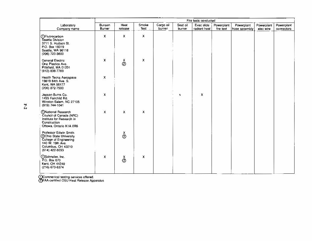
'T1 I
N
Laboratory Bunsen Company name Burner
(!)Fluorocarbon X Seattle Division 3711 S. Hudson St. P.O. Box 18319 Seattle, WA 98118 (206) 723-5600
General Electric X One Plastics Ave. Pittsfield, MA 01201 (812) 838-7769
Health Teena Aerospace X 19819 84th Ave. S. Kent, WA 98177 (206) 872-7500
Jepson-Burns Co. X 1455 Fairchild Rd. Winston-Salem, NC 27105 (919) 744-1041
(!)National Research X Council of Canada (NRC) Institute for Research in Construction Ottowa, Ontario K1A OR6
Professor Edwin Smith G)Ohio State University College of Engineering 140 W. 19th Ave. Columbus, OH 43210 (614) 422-6033
(!)Schneller, Inc. X P.O. Box 670 Kent, OH 44240 (216) 673-6374
G)commerical testing services offered. 16)FAA-certified OSU Heat Release Apparatus
Fire tests conducted Heat Smoke Cargo oil Seat oil Evac slide Powerplant Powerplant Powerplant Powerplant
release Test burner burner radiant heat fire test hose assembly elec wire connectors
X X
X X ®
' X
i
X X
X ®
X X ®
-
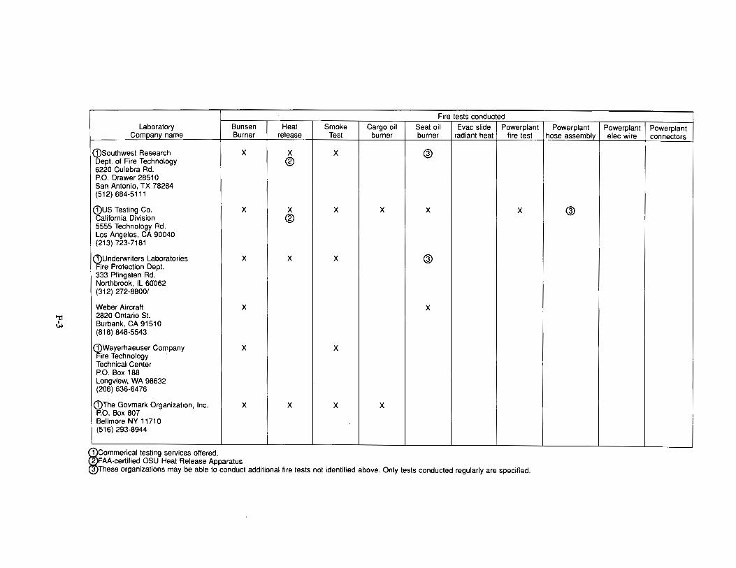
"11 I
Ul
Fire tests conducted Laboratory Bunsen Heat Smoke Cargo oil Seat oil Evac slide Powerplant
Company name Burner release Test burner burner radiant heat fire test
(Dsouthwest Research X X X @ Dept. of Fire Technology ® 6220 Culebra Rd. P.O. Drawer 28510 San Antonio, TX 78284 (512) 684-5111
(DUS Testing Co. X X X X X X California Division ® 5555 Technology Rd. Los Angeles, CA 90040 (213) 723-7181
~Underwriters Laboratories X X X @ re Protection Dept.
333 Pfingsten Rd. Northbrook, IL 60062 (312) 272-8800/
Weber Aircraft X X 2820 Ontario St. Burbank, CA 91510 (818) 848-5543
(!)Weyerhaeuser Company Fire Technology
X X
Technical Center P.O. Box 188 Longview, WA 98632 (206) 636-6476
(DThe Govmark Organization, Inc. P:o. Box 807
X X X X
Bellmore NY 1171 0 (516) 293-8944
~Commerical testing services offered. FAA-certified OSU Heat Release Apparatus These organizations may be able to conduct additional fire tests not identified above. Only tests conducted regularly are specified.
Powerplant Powerplant Powerplant hose assembly elec wire connectors
@
This page intentionally left blank
F-4
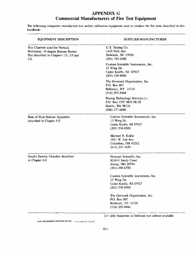
APPENDIX G Commercial Manufacturers of Fire Test Equipment
The following companies manufacture test and/or calibration equipment used to conduct the fire tests described in this handbook:
EQUIPMENT DESCRIPTION
Test Chamber used for Vertical, Horizontal, 45-degree Bunsen Burner Test described in Chapters 1.0, 2.0 and 3.0.
Rate of Heat Release Apparatus described in Chapter 5.0
Smoke Density Chamber described in Chapter 6.0
~U.S. GOVERNMENT PRINTING OFFICE: 1 aan-o;n4-061/20152
SUPPLIER/MANUFACTURER
U.S. Testing Co. 1415 Park Ave. Hoboken, NJ 07030 (201) 792-2400
Custom Scientific Instruments, Inc. 13 Wing Dr. Cedar Knolls, NJ 07927 (201) 538-8500
The Govmark Organization, Inc. P.O. Box 807 Bellmore, NY 11710 (516) 293-8944
Boeing Technology Services [l>
P.O. Box 3707 MIS 9R-28 Seattle, WA 98124 (206) 277-4600
Custom Scientific Instruments, Inc. 13 Wing Dr. Cedar Knolls, NJ 07927 (201) 538-8500
Michael B. Kukla 1011 W. 2nd Ave. Columbus, OH 43212 (614) 291-3859
Newport Scientific, Inc. 8246-E Sandy Court Jessup, MD 20794 (30 I) 498-6700
Custom Scientific instruments, Inc. 13 Wing Dr. Cedar Knolls, NJ 07927 (201) 538-8500
The Govmark Organization, Inc. P.O. Box 807 Bellmore, NY 11710 (516) 293-8944
[l> only blueprints to fabricate test cabinet available
G-1
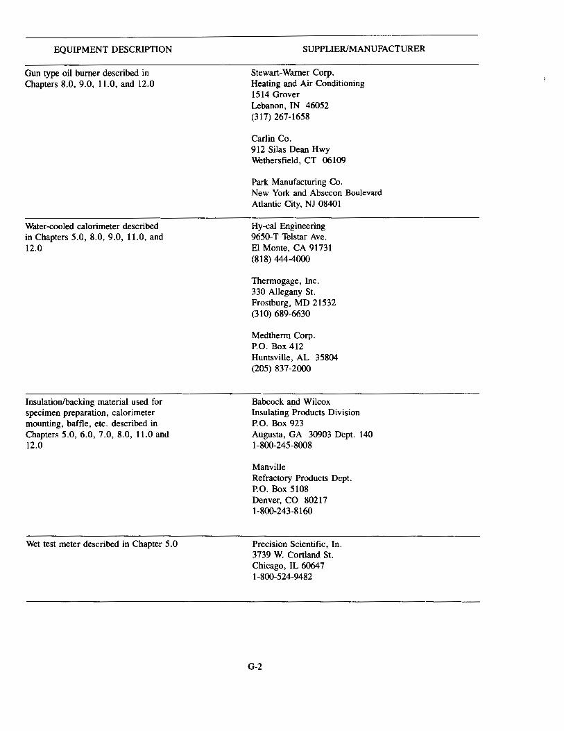
EQUIPMENT DESCRIPTION
Gun type oil burner described in Chapters 8.0, 9.0, 11.0, and 12.0
Water-cooled calorimeter described in Chapters 5.0, 8.0, 9.0, 11.0, and 12.0
Insulation/backing material used for specimen preparation, calorimeter mounting, baffle, etc. described in Chapters 5.0, 6.0, 7 .0, 8.0, 11.0 and 12.0
Wet test meter described in Chapter 5.0
SUPPLIER/MANUFACTURER
Stewart-Warner Corp. Heating and Air Conditioning 1514 Grover Lebanon, IN 46052 (317) 267-1658
Carlin Co. 912 Silas Dean Hwy Wethersfield, CT 06109
Park Manufacturing Co. New York and Absecon Boulevard Atlantic City, NJ 08401
Hy-cal Engineering 9650-T Telstar Ave. El Monte, CA 91731 (818) 444-4000
Therrnogage, Inc. 330 Allegany St. Frostburg, MD 21532 (31 0) 689-6630
Medtherrn Corp. P.O. Box 412 Huntsville, AL 35804 (205) 837-2000
Babcock and Wilcox Insulating Products Division P.O. Box 923 Augusta, GA 30903 Dept. 140 1-800-245-8008
Manville Refractory Products Dept. P.O. Box 5108 Denver, CO 80217 1-800-243-8160
Precision Scientific, ln. 3739 W. Cortland St. Chicago, IL 6064 7 1-800-524-9482
G-2