double effect absorption chiller /heater mg · pdf filedouble effect absorption chiller...
TRANSCRIPT

DOUBLE EFFECT
ABSORPTION CHILLER /HEATER
MG MODEL
1 Specifications
CH-MG150CE CH-MG200CE
Version 9.10
- 1 -
Contents Page
1. General Information 1.1 Chiller-heater ...................................... 2 1.1.1 Chiller-heater Specification …………………………. 2 1.1.2 External Dimensions ………………………….. 3 1.1.3 Sound Pressure level …………………………… 6 1.1.4 Noise Criteria ………………………….. 6 1.1.5 Horizontal Characteristics …………………………… 7 1.2 Burner
1.2.1 Burner Specifications . ......................…............. 8 1.2.2 External Dimensions ………………………….. 9
2. Principle & Operating Cycle 2.1 Cycle Diagram ………………………….. 10 2.1.1 Cooling Cycle …………………………... 10 2.1.2 Heating Cycle ………………………….. 10 2.2 Component Location …………………………. 11 2.2.1 Schematic …………………………. 12 2.2.2 Detail View …………………………. 13 2.3 Component Description …………………………. 17 2.4 Cooling and Heating Cycle …………………………. 24 2.4.1 Cooling Cycle …………………………. 24 2.4.2 Heating Cycle …………………………. 25 2.5 MG Series Part Temperature Data …………………………. 26 2.6 Equilibrium Chart ………………………… 27
- 2 -
1. General Information 1.1 Chiller-heater 1.1.1Chiller-heater Specifications
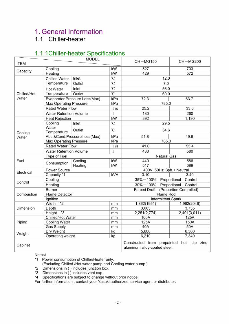
MODEL ITEM CH-MG150 CH-MG200
Capacity Cooling kW 527 703 Heating kW 429 572
Chilled/Hot Water
Chilled Water Temperature
Inlet ℃ 12.0 Outlet ℃ 7.0
Hot Water Temperature
Inlet ℃ 56.0 Outlet ℃ 60.0
Evaporator Pressure Loss(Max) kPa 72.3 63.7 Max Operating Pressure kPa 785.0 Rated Water Flow l/s 25.2 33.6 Water Retention Volume l 180 260
Cooling Water
Heat Rejection kW 892 1,190 Cooling Water Temperature
Inlet ℃ 29.5
Outlet ℃ 34.6
Abs.&Cond.Pressurel loss(Max) kPa 51.8 49.6 Max Operating Pressure kPa 785.0 Rated Water Flow l/s 41.6 55.4 Water Retention Volume l 430 580
Fuel Type of Fuel Natural Gas
Consumption Cooling kW 440 586 Heating kW 517 689
Electrical Power Source 400V 50Hz 3ph.+ Neutral Capacity *1 kVA 3.10 3.40
Control Cooling 35%-100% Proportional Control Heating 30%-100% Proportional Control
Combustion Burner Forced Draft (Proportion Controlled) Flame Detector Flame Rod Ignition Intermittent Spark
Dimension Width *2 mm 1,862(1951) 1,962(2046) Depth mm 3,663 3,735 Height *3 mm 2,251(2,774) 2,491(3,011)
Piping Chilled/Hot Water mm 100A 125A Cooling Water mm 125A 150A Gas Supply mm 40A 50A
Weight Dry Weight kg 5,600 6,500 Operating weight kg 6,210 7,340
Cabinet Constructed from prepainted hot- dip zinc-aluminum alloy-coated steel.
Notes) *1 Power consumption of Chiller/Heater only.
(Excluding Chilled /Hot water pump and Cooling water pump.) *2 Dimensions in ( ) includes junction box. *3 Dimensions in ( ) includes vent cap. *4 Specifications are subject to change without prior notice. For further information , contact your Yazaki authorized service agent or distributor.

- 3 -
1.1.2 External Dimensions
CH-MG150
- 4 -
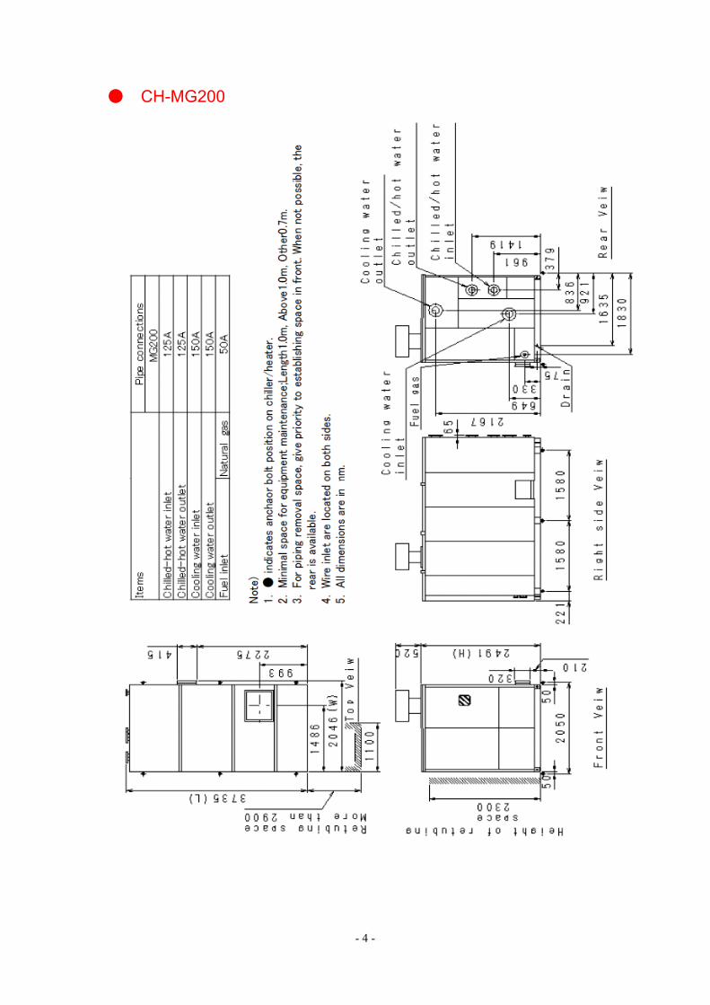
● CH-MG200

- 5 -
Vent Cap

- 6 -
1.1.3 Sound Pressure Levels Measuring point
Sound pressure level characteristics 50/60Hz Commonness
1.1.4 Noise Criteria
CH-MG150
Model Operation sound db (A) CH-MG150 74 CH-MG200 74
Note) Rating operation sound is measured in a place where influence of reflection sound is little.
- 7 -
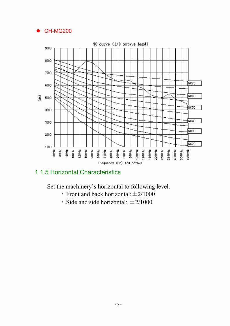
CH-MG200
1.1.5 Horizontal Characteristics
Set the machinery’s horizontal to following level. ・ Front and back horizontal:±2/1000 ・ Side and side horizontal: ±2/1000

- 8 -
1.2 Burner 1.2.1 Burner Specifications
Chiller-Heater Type CH-MG150 CH-MG20012 517 6893456
7
89 11/2inch 2inch
101112
13
Gas Type Natural gasGas Input (kW)Combustion control Proportional (100%-30%)Ignition methodAir control Servor motor(Burner accessory)Gas control Servor motor(Burner accessory)
Intermittent spark
Safety device
Safety device such as Burner controller,Wind pressure switch, Gas pressureswitch would be included in the burner asaccessory.
Flame detection Flame rodPiping sizeGas supply pressure 1.96kPaUsage temperature -20℃~60℃Usage humidity 90%(RH)
CE certificateBurner including the accessories are CEcertificated.
- 9 -
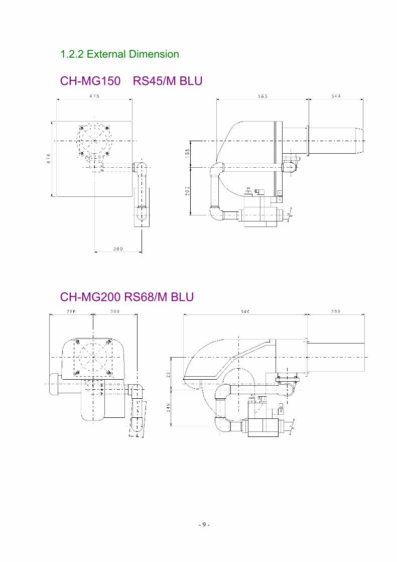
1.2.2 External Dimension CH-MG150 RS45/M BLU
CH-MG200 RS68/M BLU

- 10 -
2 Principle & Operating Cycle 2.1 Cycle Diagram 2.1.1 Cooling Cycle
2.1.2 Heating Cycle

- 11 -
2.2 Component Location
2.2.1 Schematic
2
8
9
2122
28
29
31
1
3
4
5
6
7
10
11
12
1314 15
16
17
18
19
20
23
2425
26
27
30
32
8 7
No Description No Description
1 High Temp. Generator(HGE) 17 Chilled/Hot water Inlet2 Heat Exchanger(HE) 18 Chilled/Hot water Outlet3 Field Wiring Junction Box(JB) 19 Cooling Water Inlet4 Transformer Box(TR) 20 Cooling Water Outlet5 Control Box(CB) 21 Condenser Temp. Sensor(CON)6 Gas Burner(GB) 22 Evaporator Temp. Sensor(LT)7 Changeover Valve(CVR) 23 Cooling Water Inlet Temp. Sensor(CTI)8 Solution Pump(SP) 24 Cooling Water Outlet Temp. Sensor(CTO)9 Refrigerant Proportional Valve(RPV) 25 Generator Temp. Sensor(GP)10 Refrigerant Freeze Protection Valve(SV1) 26 Generator Prevent Switch(GPS)11 Concentrated Solution Proportional Valve(CPV) 27 Chilled/Hot Water Inlet Temp. Sensor(WTI)12 Exhaust Chamber 28 Chilled/Hot Water Flow Switch(FS1)13 Fusible Plug 29 Frames14 Generator Level Switch(GLS) 30 Insulation of HGE & LGE(Glass Wool)15 Palladium Cell(Pd) 31 Insulation of EVA. (Polyethylene Form)16 Gas Supply 32 Chilled/Hot Water Outlet Temp. Sensor(WTO)

- 12 -
2.2.2 Detail View
Left side view of low temperature part
Right side view of low temperature part
LT Thermistor CON Thermistor
RPV
SV1
SPRefrigerant Sampling Valve
Solution Sampling ValveCVR1
Cooling Water Outlet
Cooling Water Intlet
CON
EVA
HHELHE
Service Valve B
Fusible Plug
Level Bar
RHE
ABS
LGENon-Condensable Gas
Palladium Cell
Gas SeparatorLow temp. concentratedSolution LHE inlet
Concentrated Solution ABS inlet
SP
Service Valve A

- 13 -
Front side view
Back side view
Non-condensable gasstorage tank(GST)
EVAABSHGE
LGE CONCooling watar outlet
Flow switch
Chilled/hotwater inlet
Chilled/hotwater outlet
CVR1
CVR2
Cooling watar inlet
Palladium cell
CON
ABSEVA
LGE
HGESV1
CPV
Service valveA and B
ControlBox
Level bar
Burner
- 14 -
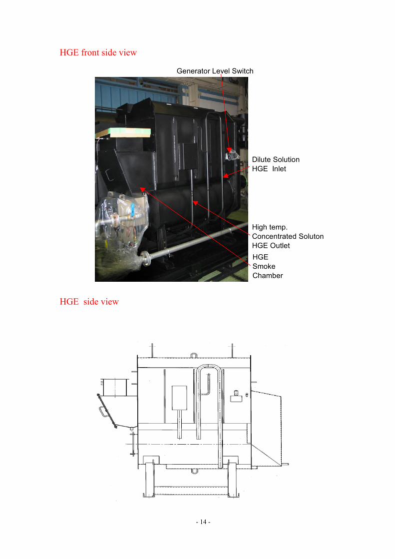
HGE front side view HGE side view
Generator Level Switch
Dilute SolutionHGE Inlet
High temp.Concentrated SolutonHGE Outlet
HGESmokeChamber

- 15 -
Front side view of Water Camber
The water chambers are separated by partitions. Since a short circuit of the cooling water and the chilling water causes capacity reduction, the partitions of the water chambers include rubber packing. The perimeter packing works to avoid water leakage and any trouble with flooding and wasting water. Pay attention to rubber degradation and mounting of packing.
Inside the water chambers are painted with tar epoxy for prevention of rust. This is different from the
black paint used on the other parts of the machine Back side view of Water Camber
ABS tube
ABS partitionrubber packing
ABS perimeterrubber packing
EVA tube
EVA partitionrubber packing
EVA partitionrubber packing
ABS water chamber
- 16 -
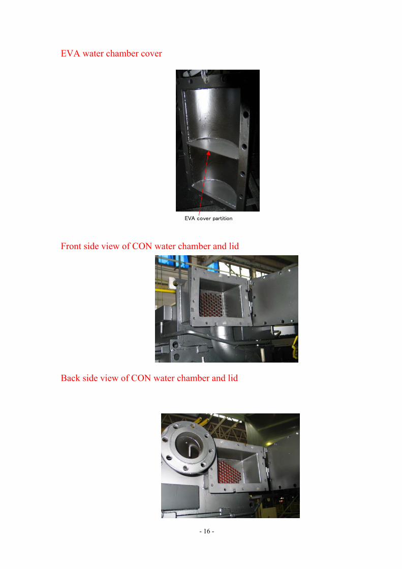
EVA water chamber cover Front side view of CON water chamber and lid Back side view of CON water chamber and lid
EVA cover partition

- 17 -
2.3 Component Description

- 18 -
No. Component Description
1 HGE
(High temp generator)
Combustion of fuel boils lithium bromide solution in the
HGE to commence separation of refrigerant from the
absorbent
2 Burner Device for combusting fuel (gas).
3 Smoke Chamber
For leading the exhaust gas to the chimney.
The Heat transfer pipe can be cleaned by removing the
lid.
4
Chimney
For the safe direction of products of combustion for
discharge to atmosphere.
5 Separator Baffle For separating dilute LiBr solution from the refrigerant
vapor.
6 Refrigerant vapor entry To transfer refrigerant vapor into the LGE heat exchange
tube.
7 LGE (low temp generator) To enable secondary boiling of the dilute LiBr solution to
liberate additional refrigerant.
8 LGE separator Secondary separator to remove concentrated LiBr
solution from the lifting secondary refrigerant vapor.
9 Fusible plug A safety device to ensure the hermetic section of the
absorption system cannot be over pressurized.
10 Condenser Heat exchange tube cooled by an external cooling tower
for condensing the secondary refrigerant vapor.
11 Refrigerant liquid
storage vessel
For accumulating refrigerant liquid storage resulting from
the function of RPV.
12 Refrigerant Proportional
Control Valve (RPV)
Electromagnetic proportional valve for control the LiBr
solution concentration and improvement of the stability of
chilled water temperature.
13 Refrigerant service valve Valve used to draw refrigerant samples when necessary.
14 Refrigerant bypass pipe
For leading refrigerant to evaporator which doesn’t empty
into refrigerant liquid storage vessel. If the RPV is closed,
the excess refrigerant held in the refrigerant liquid
storage vessel will be allowed to overflow to the
evaporator.
- 19 -
No. Component Description
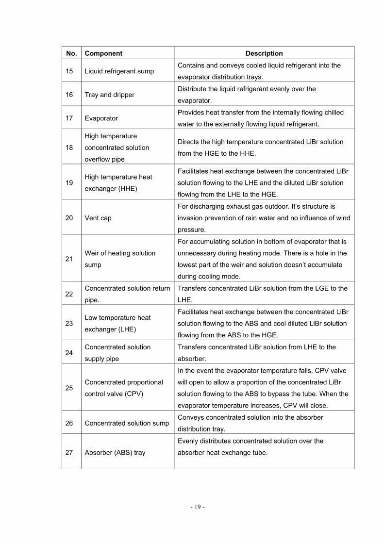
15 Liquid refrigerant sump Contains and conveys cooled liquid refrigerant into the
evaporator distribution trays.
16 Tray and dripper Distribute the liquid refrigerant evenly over the
evaporator.
17 Evaporator Provides heat transfer from the internally flowing chilled
water to the externally flowing liquid refrigerant.
18
High temperature
concentrated solution
overflow pipe
Directs the high temperature concentrated LiBr solution
from the HGE to the HHE.
19 High temperature heat
exchanger (HHE)
Facilitates heat exchange between the concentrated LiBr
solution flowing to the LHE and the diluted LiBr solution
flowing from the LHE to the HGE.
20 Vent cap
For discharging exhaust gas outdoor. It‘s structure is
invasion prevention of rain water and no influence of wind
pressure.
21 Weir of heating solution
sump
For accumulating solution in bottom of evaporator that is
unnecessary during heating mode. There is a hole in the
lowest part of the weir and solution doesn’t accumulate
during cooling mode.
22 Concentrated solution return
pipe.
Transfers concentrated LiBr solution from the LGE to the
LHE.
23 Low temperature heat
exchanger (LHE)
Facilitates heat exchange between the concentrated LiBr
solution flowing to the ABS and cool diluted LiBr solution
flowing from the ABS to the HGE.
24 Concentrated solution
supply pipe
Transfers concentrated LiBr solution from LHE to the
absorber.
25 Concentrated proportional
control valve (CPV)
In the event the evaporator temperature falls, CPV valve
will open to allow a proportion of the concentrated LiBr
solution flowing to the ABS to bypass the tube. When the
evaporator temperature increases, CPV will close.
26 Concentrated solution sump Conveys concentrated solution into the absorber
distribution tray.
27 Absorber (ABS) tray
Evenly distributes concentrated solution over the
absorber heat exchange tube.

- 20 -
No. Component Description
28 Absorber (ABS)
Cooling water from the cooling tower flows internally in
the absorber heat exchange tube.
The cooled, concentrated LiBr solution flowing externally
over the tube establishes a vapor pressure under which
liquid refrigerant changes phase in the evaporator.
The resultant refrigerant vapor from the evaporator is
absorbed by the concentrated solution, it thus becomes
diluted before returning to the HGE.
29 Dilute solution sump strainer
The suction intake pipe of the solution pump (SP)
connected to the base of the ABS is provided with a
strainer to preclude particles of any foreign matter
entering the pump.
30 Solution pump
Required to transfer cool, diluted LiBr solution from the
base of the ABS to the heat exchanger and thereafter to
the HGE.
31 Check valve (BV)
A flow non-return valve (BV) is located between the SP
and HGE to accommodate the pressure difference back-
flow potential. And for boil-dry protection of HGE.
32 Dilute solution bypass pipe For leading some dilute solution from LHE outlet to LGE.
33 Solenoid valve (SV1)
If the operation of RPV and CPV does not prevent the
evaporator temperature from declining to 1°C, SV1
solenoid valve will open to allow concentrated LiBr
solution to enter the evaporator liquid refrigerant
reservoir.
34 Ejector inlet pipe For leading dilute solution from SP to ejector.
35 Dilute solution cooling box Cooling the dilute solution led to the ejector by invalid
refrigerant.
36 Ejector
Using pressured cooled dilute solution as a driving fluid to
make lower pressure than ABS to extact non-
condensable gas. It is also extractive in similar principle
during heating.
37 Extraction steam pipe For leading non-condensable gas from ABS to ejector.
38 Gas-liquid return pipe Extracted non-condensable gas at ejector and driving
fluid are mixed and led to gas separator.
39 Gas storage chamber inlet
pipe
Pipe for leading some dilute solution to gas storage
chamber.

- 21 -
No. Component Description
40 Non-condensable gas
storage vessel outlet pipe
Pipe for returning dilute solution from gas storage
chamber
41 Non-condensable gas
separator
For separating dilute solution from gas-liquid down pipe
and gas.
42
Non-condensable gas
storage vessel ascending
pipe
Pipe for leading non-condensable gas separated at the
separator to gas storage chamber.
43 Non-condensable gas
storage vessel
For retaining non-condensable gases accumulating in the
absorption circuit.
44 Palladium cell
Hydrogen gas is automatically removed from the
hermetic section of the chiller-heater by the palladium
cell.
45 Non-condensable gas
service valve
To facilitate the vacuum service procedure to remove
stored non-condensable gases.
46 Solution return pipe Pipe for returning solution from non-condensable gas
separator.
47 Absorber service valve To facilitate the vacuum service of the absorber area of
the absorption circuit.
48 Solution change-over valve
(CVR1)
CVR1 is an electrically operated valve for selecting
heating and cooling modes of operation.
49 Refrigerant evaporation
change-over valve (CVR2)
CVR2 is an electrically operated valve for selecting
heating and cooling modes of operation.
50 HGE pressure sensor (HPS)
HPS is installed at LGE manifold and the LGE tube
pressure is Measured. (LGE≒HGE pressure)
・Protection stop at HGE≧750mmHg
・SP inverter is controlled by HGE pressure at cooling
mode.
51 No USE
No USE
- 22 -
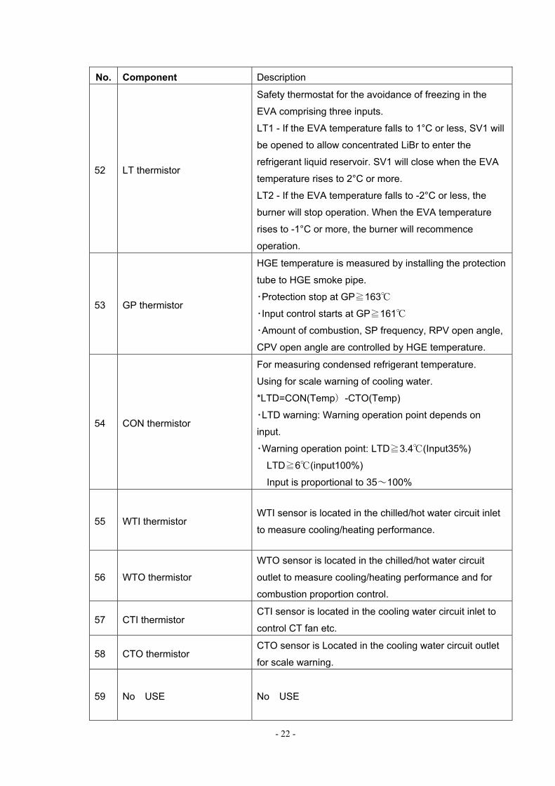
No. Component Description
52 LT thermistor
Safety thermostat for the avoidance of freezing in the
EVA comprising three inputs.
LT1 - If the EVA temperature falls to 1°C or less, SV1 will
be opened to allow concentrated LiBr to enter the
refrigerant liquid reservoir. SV1 will close when the EVA
temperature rises to 2°C or more.
LT2 - If the EVA temperature falls to -2°C or less, the
burner will stop operation. When the EVA temperature
rises to -1°C or more, the burner will recommence
operation.
53 GP thermistor
HGE temperature is measured by installing the protection
tube to HGE smoke pipe.
・Protection stop at GP≧163℃
・Input control starts at GP≧161℃
・Amount of combustion, SP frequency, RPV open angle,
CPV open angle are controlled by HGE temperature.
54 CON thermistor
For measuring condensed refrigerant temperature.
Using for scale warning of cooling water.
*LTD=CON(Temp)-CTO(Temp)
・LTD warning: Warning operation point depends on
input.
・Warning operation point: LTD≧3.4℃(Input35%)
LTD≧6℃(input100%)
Input is proportional to 35~100%
55 WTI thermistor WTI sensor is located in the chilled/hot water circuit inlet
to measure cooling/heating performance.
56 WTO thermistor
WTO sensor is located in the chilled/hot water circuit
outlet to measure cooling/heating performance and for
combustion proportion control.
57 CTI thermistor CTI sensor is located in the cooling water circuit inlet to
control CT fan etc.
58 CTO thermistor CTO sensor is Located in the cooling water circuit outlet
for scale warning.
59 No USE
No USE
- 23 -
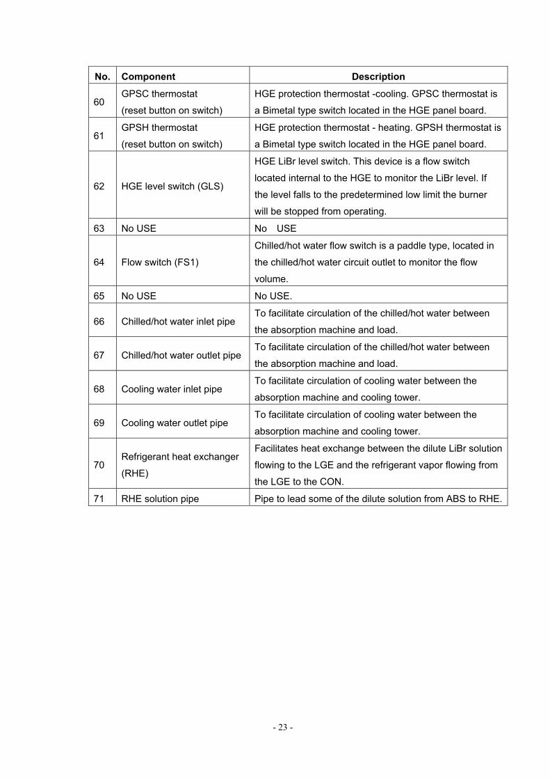
No. Component Description
60 GPSC thermostat
(reset button on switch)
HGE protection thermostat -cooling. GPSC thermostat is
a Bimetal type switch located in the HGE panel board.
61 GPSH thermostat
(reset button on switch)
HGE protection thermostat - heating. GPSH thermostat is
a Bimetal type switch located in the HGE panel board.
62 HGE level switch (GLS)
HGE LiBr level switch. This device is a flow switch
located internal to the HGE to monitor the LiBr level. If
the level falls to the predetermined low limit the burner
will be stopped from operating.
63 No USE No USE
64 Flow switch (FS1)
Chilled/hot water flow switch is a paddle type, located in
the chilled/hot water circuit outlet to monitor the flow
volume.
65 No USE No USE.
66 Chilled/hot water inlet pipe To facilitate circulation of the chilled/hot water between
the absorption machine and load.
67 Chilled/hot water outlet pipe To facilitate circulation of the chilled/hot water between
the absorption machine and load.
68 Cooling water inlet pipe To facilitate circulation of cooling water between the
absorption machine and cooling tower.
69 Cooling water outlet pipe To facilitate circulation of cooling water between the
absorption machine and cooling tower.
70 Refrigerant heat exchanger
(RHE)
Facilitates heat exchange between the dilute LiBr solution
flowing to the LGE and the refrigerant vapor flowing from
the LGE to the CON.
71 RHE solution pipe Pipe to lead some of the dilute solution from ABS to RHE.

- 24 -
2.4 Cool & Heating Cycle
2.4.1 Cooling Cycle (Numbers correspond to 2.3 Component Description)
1. Dilute LiBr solution is pumped to the high temperature generator, HGE (1), and is heated by the direct-fired gas burner (2). As the Lithium Bromide (LiBr) solution temperature is raised, refrigerant vapor is liberated from solution as the refrigerant is brought to the boiling point. As the refrigerant is liberated the solution concentration is raised, some concentrated solution is entrained in the liberated refrigerant and when it comes in contact with the separator baffles (5) the solution drops back into the HGE sump. The refrigerant vapor travels to the low temperature generator (LGE) tubes.
2. The separated high temperature refrigerant vapor flows to LGE (7) tubes and heats
the dilute solution that flows from the low temperature heat exchanger outlet through dilute solution bypass pipe (32). The refrigerant flowing through the LGE tubes generates additional refrigerant vapor out of the dilute solution. The refrigerant vapor in the tubes is condensed as heat is transferred to the dilute solution and the refrigerant liquid flows to the refrigerant heat exchanger RHE (70). Here, the refrigerant liquid is cooled by the heat transfer with dilute solution and then flows to the condenser (10).
3. Refrigerant vapor and low temperature concentrated solution from the LGE (7) are
separated by the LGE baffles(8). Refrigerant vapor enters the condenser, (10) where the heat of condensation is removed by the cooling water flowing through the condenser tubes. Some resultant condensate (refrigerant liquid) mixes with the refrigerant vapor that has been condensed in the condenser and collects in the refrigerant storage vessel (11), flows out to the liquid refrigerant sump (15) through refrigerant bypass pipe (14) and through RPV (12), and then on to the evaporator through the evaporator tray drippers (16). As the refrigerant enters the liquid refrigerant sump (15) through the refrigerant bypass pipe (14), the bypass pipe acts as a metering device, the refrigerants pressure is reduced to that of the evaporator, and as the pressure is lowered some of the refrigerant flashes and cools the remaining refrigerant to evaporator temperature.
4. Since the EVA (17) is at a substantially lower pressure than the condenser, the liquid evaporates as it flows over the surface of the chilled-hot water tubes. The heat of circulating chilled water is removed from refrigerant evaporation, transferred to the refrigerant vapor and the temperature of the chilled water is lowered.
5. In the HGE, the high temperature concentrated solution that was separated out of
the refrigerant vapor stream by the separator baffle (5) flows to the high temperature heat exchanger HHE (19) via high temperature concentrated solution return pipe (18) and is cooled by a heat transfer with the dilute solution flowing through the HHE toward the HGE. The concentrated solution then flows through an orifice and into a mixing box. The mixing box combines this solution and that returning from the concentrated solution return pipe (22) from the LGE before entering the low temperature heat exchanger LHE (23).

- 25 -
6. Refrigerant is liberated out of the dilute solution in the low temperature generator
LGE (7) by the high temperature refrigerant vapor flowing through the LGE tubes, and as the liberated vapor rises and comes in contact with the LGE separator baffles the solution falls back into the LGE sump and the refrigerant vapor travels to the condenser.
7. The solution after leaving the LGE is mixed with concentrated solution, leaving the
high temperature heat exchanger. As the mixed solution enters the low temperature heat exchanger (23) it is cooled by dilute solution from the absorber (21) before traveling to the concentrated solution sump (26) and then to the absorber dripper trays (27) for equal distribution over the absorber tube bundle.
8. As the equally dripped concentrated solution flows into the absorber it absorbs
refrigerant vapor from the evaporator (17). As the refrigerant vapor is absorbed by the concentrated solution it creates a low pressure area that continuously draws refrigerant vapor from the evaporator. In addition the absorbing of refrigerant vapor causes the solution to give up its heat of vaporization. As the refrigerant vapor is condensed it releases its heat of vaporization. In addition as the refrigerant mixes with the concentrated solution and condenses it also releases a heat of dilution which is transferred to the solution. This heat of dilution and the heat of vaporization are transferred to the cooling water flowing through the absorber tubes. As the refrigerant vapor is absorbed into solution the solution concentration is lowered.
9. The solution pump, SP (30), pumps the dilute solution to LGE. This solution is first
pumped to RHE (70) via solution pipe (71) then to the LGE. Most of the dilute solution is divided into two after flowing through LHE (23). 50% flows to the HGE (1) via HHE (19), 35% flows to LGE via dilute solution bypass pipe (32), and 15% flows to the RHE via RHE solution pipe (71).
10. When the solution returns to the HGE (1), the dilute solution is again heated by the
gas burner and the cycle is repeated from 1~9. The concentrated density of solution of HGE (1) and LGE (7) are nearly equal.
2.4.2 Heating Cycle (Numbers correspond to 2.3 Component Description) 1. Dilute LiBr solution is heated in the HGE by the gas burner in precisely the same
manner as the cooling cycle. Hot vapor flows to the evaporator via refrigerant vapor change-over valve CVR2 (49) and the concentrated solution flows to the lower part of the ABS (28) via solution change-over valve CVR1(48).
2. Hot refrigerant vapor flows to the evaporator (17) and condenses on the surface of
the evaporator tubes. The heat of condensation is transferred from the circulating hot water, and as heat is transferred the water temperature is raised.
3. Hot refrigerant vapor which is condensed on the surface of the evaporator tubes is
condensed and mixes with the concentrated solution. As the refrigerant is absorbed into solution the solution concentration lowers. The SP(30) pumps the dilute solution

- 26 -
through the LHE (23).The dilute solution is divided into two after flowing through the LHE(23) . One half returns to the lower part of the ABS(28) again via dilute solution bypass pipe(32), LGE (7), concentrated solution return pipe (22), LHE(23) and CPV (25). The other half returns to HGE (1) via HHE (20).
4. Dilute solution which returned to HGE (1) is again heated by the gas burner (2 ) and
the cycle is repeated from 1~3. 2.5 MG Series Part Temperature Data (Representative) In Cooling Operation Input 100% 100% 80% 60% 44%
Cooling water temp ℃ 32 29.5 31 30 29.0
Dilute solution
SP outlet temp ℃ 37 35 35 34 32
LHE outlet temp ℃ 75 73 73 71 68
HGE inlet temp ℃ 133 131 129 125 119
RHE outlet temp ℃ 72 69 66 60 56
High temp concentrated solution
HGE outlet temp ℃ 155 153 148 141 132
HHE outlet temp ℃ 80 79 78 76 72
Low temp concentrated solution LGE outlet temp ℃ 89 87 85 80 75
Concentrated solution ABS inlet temp ℃ 42 41 41 40 37
Liquid refrigerant RHE inlet temp ℃ 92 89 87 83 77
RHE outlet temp ℃ 60 61 58 57 54
Evaporator temperature ℃ 6.9 6.7 6.6 4.5 4.1
Condenser temperature ℃ 40 38 38 35 33
High temp generator temperature ℃ 158 155 151 143 135
Exhaust gas temperature ℃ 198 195 179 160 143
High temp generator pressure kPa 87 84 73 61 49
※ Table above is Representative data of MG150. Value will change by refrigeration capacity,
amount of cooling water circulation, level of adhesion of scale and slime, and vacuum level, therefore use only as reference value.
- 27 -
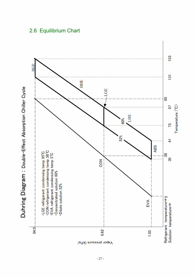
2.6 Equilibrium Chart