double o-ring installation geothermal … · 2012-07-10 · installation instructions double o-ring...
TRANSCRIPT

Manual 2100-518A
Page 1 of 30
Manual: 2100-518A
Supersedes: 2100-518
File: Volume I, Tab 8
Date: 07-08-11
INSTALLATION
INSTRUCTIONS
DOUBLE O-RING
GEOTHERMAL
FLOW CENTERS
Models: DORFC-1 DORFC-2
BMC, Inc.
Bryan, Ohio 43506
DORFC-1 DORFC-2

Manual 2100-518A
Page 2 of 30
CONTENTS
Getting Other Informations and Publications ........ 3
General InformationFlow Center Nomenclature ...................................... 4
ApplicationDescription ............................................................... 4Safety ................................................................ 4Danger ................................................................ 4Warning ................................................................ 4Caution ................................................................ 4Notice ................................................................ 4
Flow Center Mounting InstructionsNotice ................................................................ 7Stud Wall ................................................................ 7Concrete/Masonry Wall ........................................... 7Side of Unit .............................................................. 7
Piping InstallationDescription ............................................................. 10Actual Photo Images ........................................ 10-11
Multiple Unit to Single Loop ConnectionDescription ............................................................. 12
Flow Center WiringDescription ............................................................. 16
Flushing & ChargingGeneral .............................................................. 18Procedures for Adding Antifreeze .......................... 18Flushing & Filling Earth Loop & Units .................... 22Flushing Earth Loop Only ...................................... 22Flushing Unit Only ................................................. 23
Flow Center Initial StartupGeneral .............................................................. 24Procedures for Pressurizing the System ............... 24Pressure/Temperature Plugs ................................. 24
TroubleshootingTroubleshooting Table ........................................... 27
Antifreeze Selection & UseGeneral .............................................................. 28Methanol .............................................................. 28Ethanol .............................................................. 28Propylene Glycol ................................................... 29Potassium Acetate (GS4) ...................................... 29Antifreeze Verification ............................................ 30
Figures
Figure 1A Performance Model DORFC-1 ................ 5
Figure 1B Performance Model DORFC-2 ................ 5
Figure 2 Flow Center Dimensions ......................... 6
Figure 3 Pump Horizontal Applications ................. 8
Figure 4A Mounting - Studded Wall ......................... 9
Figure 4B Mounting - Masonry Wall ........................ 9
Figure 5A Flow Center Connection to GV Series .. 12
Figure 5B Flow Center Connection to GT Series .. 13
Figure 5C Flow Center Connection to QW Series . 14
Figure 6 Multiple Unit Connection to Singular ..... 15
Figure 7 Electrical Connections .......................... 17
Figure 8 Connecting Flush Cart to Flow Center .. 19
Figure 9A Positioning - Flush Loop ....................... 20
Figure 9B Positioning - Flush Loop & Unit ............ 20
Figure 9C Positioning - Flush Unit ......................... 21
Figure 9D Positioning - Operation ......................... 21
Figure 10 Pressure Temperature Ports ................. 25
Figure 11 Density Verification - Solution Strength ... 30
Tables
Table 1 Fusion or Barbed Fittings ...................... 10
Table 2 Electrical Ratings .................................. 16
Table 3A GV Series Coil Pressure Drop .............. 25
Table 3B GT Series Coil Pressure Drop .............. 26
Table 3C QW Series Coil Pressure Drop ............. 26
Table Troubleshooting .................................... 27
Table 4 Fluid Volume ......................................... 29
Table 5 Percentages by Volume ........................ 29
Table 6 Propylene Glycol Specific Gravity ......... 30
Table 7 Methanol Specific Gravity ..................... 30

Manual 2100-518APage 3 of 30
GETTING OTHER INFORMATION AND PUBLICATIONS
These publications can help you install the air
conditioner or heat pump. You can usually find these at
your local library or purchase them directly from the
publisher. Be sure to consult current edition of each
standard.
National Electrical Code ...................... ANSI/NFPA 70
Standard for the Installation .............. ANSI/NFPA 90A
of Air Conditioning and Ventilating Systems
Standard for Warm Air ...................... ANSI/NFPA 90B
Heating and Air Conditioning Systems
Load Calculation for Residential ....... ACCA Manual J
Winter and Summer Air Conditioning
Duct Design for Residential ............. ACCA Manual D
Winter and Summer Air Conditioning and Equipment
Selection
Closed-Loop/Ground Source Heat Pump ........ IGSHPA
Systems Installation Guide
Grouting Procedures for Ground-Source ......... IGSHPA
Heat Pump Systems
Soil and Rock Classification for ...................... IGSHPA
the Design of Ground-Coupled Heat Pump Systems
Ground Source Installation Standards ............. IGSHPA
Closed-Loop Geothermal Systems .................. IGSHPA
– Slinky Installation Guide
FOR MORE INFORMATION, CONTACTTHESE PUBLISHERS:
ACCA Air Conditioning Contractors of America
1712 New Hampshire Avenue
Washington, DC 20009
Telephone: (202) 483-9370
Fax: (202) 234-4721
ANSI American National Standards Institute
11 West Street, 13th Floor
New York, NY 10036
Telephone: (212) 642-4900
Fax: (212) 302-1286
ASHRAE American Society of Heating Refrigerating,
and Air Conditioning Engineers, Inc.
1791 Tullie Circle, N.E.
Atlanta, GA 30329-2305
Telephone: (404) 636-8400
Fax: (404) 321-5478
NFPA National Fire Protection Association
Batterymarch Park
P.O. Box 9101
Quincy, MA 02269-9901
Telephone: (800) 344-3555
Fax: (617) 984-7057
IGSHPA International Ground Source
Heat Pump Association
490 Cordell South
Stillwater, OK 74078-8018

Manual 2100-518APage 4 of 30
GEOTHERMAL FLOW CENTERS NOMENCLATURE
FLOW CENTER DESCRIPTION
The DORFC Series Flow Centers are a compact, easy to
mount polystyrene cabinet that contains 3-way valves and
pump(s) with connections for flushing, filling and pumping
fluids for geothermal closed loop systems. The proven
design is foam insulated to prevent condensation and full
flow service valves minimize pressure drop.
One or two Grundfos pump models UP26-99 are available
based upon flow requirements and loop design.
Unit and loop connections are designed for double o-ring
fittings with several varieties of connections available
(fusion, threaded, barbed and sweat). Pump motor(s) are
230VAC, 60 Hz, 1-phase.
An attractive light gray polystyrene cabinet (that matches
geothermal unit) with black pump(s) provides an
aesthetically pleasing enclosure for pump(s) and valves.
SAFETY
Warnings, cautions and notices appear throughout this
Manual. Read these items carefully before attempting any
installation, service or troubleshooting of the equipment.
DANGER
Indicates an immediate hazardous situation which, if not
avoided, will result in death or serious injury. DANGER
labels on unit access panels must be observed.
WARNING
Indicates a potentially hazardous situation which, if not
avoided, will result in death or serious injury.
CAUTION
Indicates a potentially hazardous situation or an unsafe
practice which, if not avoided, could result in minor or
moderate injury or product or property damage.
NOTICE
Notification of installation, operation or maintenance
information, which is important, but which is not hazard-
related.
DORFC 2
1 = 1-Pump Version, 208/230V, 60 Hz, 1-phase, 22' HD @ 16 GPM
2 = 2-Pump Version, 208/230V, 60 Hz, 1-phase, 44' HD @ 16 GPM
Double
O-Ring
Flow
Center
WARNINGFailure to do so could cause property
damage, bodily harm or death.
CAUTIONFailure to do so could cause property
damage, bodily harm or death.

Manual 2100-518APage 5 of 30
0
10
20
30
40
50
60
70
0 5 10 15 20 25 30 35
Flow (GPM)
He
ad
(F
ee
t)
FIGURE 1B
PERFORMANCE MODEL DORFC-2 FLOW CENTER
0
5
10
15
20
25
30
35
0 5 10 15 20 25 30 35
Flow (GPM)
He
ad
(F
ee
t)
FIGURE 1A
PERFORMANCE MODEL DORFC-1 FLOW CENTER
FLOW CENTER PERFORMANCE

Manual 2100-518APage 6 of 30
GF
B
D
H
MIS-2658
11.431.5 5.1 6.7 12.719.1
A B C D E F G H
INCHES 13.5 10.3 7.5 12.4 2.0 2.6 5.0 4.7
CM 34.3 26.2
TYPE SHIPPING WEIGHT
DORFC-1 26 LBS
DORFC-2 31 LBS
C
A
DIMENSIONAL DRAWING
FIGURE 2
FLOW CENTER DIMENSIONS

Manual 2100-518APage 7 of 30
NOTICE
The Flow Center must be mounted with the pump shaft in
the horizontal position. In other words, it should always be
mounted in a vertical position (not on its back or mounted
to the ceiling). See Figure 3.
The pump should be located as close to the unit as possible
to limit the length of rubber hose kit or interconnect piping
and thus its associated pressure drop.
STUD WALL
Mounting on stud wall with or without drywall can be
accomplished by using two (2) lag bolts through the top
and bottom center holes directly into the stud. See Figure
4A.
CONCRETE/MASONRY WALL
Mounting onto a concrete wall can be accomplished
typically using four (4) 1/4" diameter tapcon cement screws
in the four (4) outer corner mounting holes. See Figure 4B.
SIDE OF UNIT
Mounting on the side of the unit is possible, but not
necessarily recommended because it can inhibit
serviceability and also lead to vibration of the sheet metal
casing. It could also lead to puncturing an internal
refrigerant or water pipe. If necessary, however, the flow
center can be mounted to the sheet metal casing utilizing
four (4) self-drilling screws. (Pay close attention not to
puncture internal components.)
FLOW CENTER MOUNTING
CAUTIONThe following instructions represent industry
accepted installation practices for closed-loop
earth coupled (ground loop) installations.
Instructions are provided to assist the contractor
in installing trouble free ground loops. These
instructions are recommendations only. State/
provincial and local codes MUST be followed
and installation MUST conform to ALL
applicable codes. It is the responsibility of the
installing contractor to determine and comply
with ALL applicable codes and regulations.

Manual 2100-518APage 8 of 30
OK
HORIZONTAL
OKIMPELLER SHAFT
HORIZONTALIMPELLER SHAFT
MIS-2659
NOIMPELLER SHAFT
CAN NOT BEVERTICAL
FIGURE 3
PUMP HORIZONTAL APPLICATIONS

Manual 2100-518APage 9 of 30
1/4" TAPCON SCREWS
MIS-2660
1/4" LAG BOLTSDIRECTLY INTO STUD
FIGURE 4
MOUNTING
FIGURE 4A
Studded Wall Mounting
FIGURE 4B
Masonry Wall Mounting

Manual 2100-518APage 10 of 30
The Flow Center features Double O-Ring fittings for
installation flexibility and ease of installation – maintaining
a reliable connection. Table 1 illustrates the connection
options available for Flow Centers. Pressure drop in piping
systems should be calculated to ensure adequate flow
through the unit. All piping should be properly insulated
with closed cell insulation of 1/2" wall thickness. Piping
insulation should be glued and sealed to prevent
condensation using closed cell insulation glue. The swivel
connectors on the flow center and at the unit are designed
to be hand-tightened only.
NOTE: Apply petroleum jelly to O-Rings to prevent
damage and aid in insertion.
Loop side piping is typically polyethylene piping directly into
the flow center. Connection to the flow center can be made
with either a fusion or barbed fitting as shown in Table 1.
Connection between the flow center and the geothermal
heat pump typically would be made using the hose kit
(DORLFCK-1), which contains all fittings necessary for
connection between the heat pump and the flow center as
shown in Figure 5. Other variety of materials may also be
used for this connection - such as PE or copper piping.
noitpircseD rebmuNtraP
gniR-OelbuoDXnoisuFEP"4/1-1 S-521FROD
tiKretneCwolFpooLgniR-OelbuoD 1-KCFLROD
)spmalcesoh}4{sedulcni(gniR-OelbuoDXbraB"1 CH4-S-1BROD
gniR-OelbuoDXTPM"1 S-1PMROD
gniR-OelbuoDXTPF"1 S-1PFROD
)sgnittifT/P}2{sedulcni(gniR-OelbuoDXtaewSreppoC"1 S-1SROD
)sgnittifT/P}2{dnaspmalcesoh}4{sedulcni(woblE°09gniR-OelbuoDXbraBesoH"1 CH4-09-1BROD
)sgnittifT/P}2{sedulcni(woblE°09,gniR-OelbuoDXTPM"1 09-1PMROD
woblE°09gniR-OelbuoDXkcoLmaCtcennoCkciuQ 09-1LCROD
)xobrepeceip-1(gniR-OelbuoDXdaerhTesoHnedraGelaM TMHGROD
1-1/4" Socket Fusion X
Double O-ring
DORF125-S
1" Hose Barb X
Double O-ring
DORB1-S-4HC
1" MPT X Double O-ring
DORMP1-S
PIPING INSTALLATION
TABLE 1
NOTE: All fittings boxed in pairs (2-pieces each) will exception of DORGHMT.

Manual 2100-518APage 11 of 30
1" Swivel X Double O-ring
DORFP1-S
1" Copper Sweat X Double O-ring with 1/4"
FPT Port & Pressure/Temperature Test Plugs
DORS1-S
Elbow, 1" Hose Barb X Double
O-ring with 1/4" Port and
Pressure/Temperature Test Plugs
DORB1-90-4HC
Elbow, 1" MPT X Double
O-ring with 1/4" Port and
Pressure/Temperature Test Plugs
DORMP1-90
1" Cam Lever Male X
Double O-ring
DORCL1-90
Garden Hose Male X O-ring
(single) Adapter
DORGHMT
PIPING INSTALLATION (CONTINUED)
NOTES:
1. Apply petroleum jelly to O-Rings to prevent damage and aid in insertion.
2. Use two (2) stainless steel clamps per connection (included quantities of hose clamps with fittings and hose kits are
per this recommendation).
3. Adaptors required from 1" MPT, 1" FPT, Copper, etc. provided by others.

Manual 2100-518APage 12 of 30
MULTIPLE UNIT TO SINGLE LOOPCONNECTION
In instances where multiple units are connected to a
singular loop, our recommendation is to apply a flow
center to each individual system with full-port balancing
valves installed on each unit. See Figure 6.
FIGURE 5A
FLOW CENTER CONNECTION TO GV SERIES MODEL
MIS-2621 A
PUMP
WALL BRACKETFIELD-FABRICATED
WATER IN
HOSE CLAMPS
PIPE TO GROUND LOOP
PIPE FROM
STRAIGHT BARBEDBRASS ADAPTERS
MODULE
WATER OUT
1" FLEXIBLE HOSE
GROUND LOOP
OPTIONAL VISUALFLOW METERNOTE: IF USED SUPPORT WITH A
NOTE: APPLY PETROLEUM JELLYTO O-RINGS TO PREVENT DAMAGEAND AID IN INSERTION.

Manual 2100-518APage 13 of 30
FIGURE 5B
FLOW CENTER CONNECTION TO GT SERIES MODEL
NOTE: APPLY PETROLEUM JELLYTO O-RINGS TO PREVENT DAMAGEAND AID IN INSERTION
WATER IN
WATER OUT
GOUND LOOPPIPE FROM GROUND LOOP
PIPE TO
BRASS ADAPTERS
NOTE: IF USED SUPPORT
WALL BRACKETWITH A FIELD FABRICATED
1" FLEXIBLE HOSE
HOSE CLAMPS
FLOW METEROPTIONAL VISUAL
STRAIGHT BARBED
PUMP MODULE
MIS-2827 A

Manual 2100-518APage 14 of 30
FIGURE 5C
FLOW CENTER CONNECTION TO QW SERIES MODEL
NOTE: Apply petroleumjelly to o-rings to prevent
damage and aid in insertion
MIS-2748 A
FLEXIBLE HOSE
for Model No.)(See Spec Sheet
GROUND LOOPPIPE FROM
PUMP MODULE
PIPE TO GROUND LOOP
WATEROUT

Manual 2100-518APage 15 of 30
GR
OU
ND
FU
LL P
OR
T B
ALL
VA
LVE
FO
R B
ALA
NC
ING
LOO
P
4. A
ll un
its m
ust i
nclu
de P
/T p
orts
for
flow
rat
e m
easu
re a
nd b
alan
cing
.
FIE
LD S
UP
PLI
ED
MIS
-266
4
NO
TE
S:
1. P
ipin
g is
sho
wn
sche
mat
ical
ly.
Act
ual p
ipe
diam
eter
and
layo
ut m
ust b
e de
term
ined
bef
ore
inst
alla
tion.
2. P
ress
ure
drop
cal
cula
tion
mus
t be
mad
e to
ver
ify th
at p
aral
lel p
umpi
ng a
rran
gem
ent p
rovi
des
enou
gh h
ead
to d
eliv
er d
esig
n flo
w r
ate
to e
ach
unit
w
hen
all u
nits
are
ope
ratin
g.3.
Flo
w c
ontr
olle
r sh
ould
be
mou
nted
clo
se e
noug
h to
uni
t to
mai
ntai
n sh
ort (
apro
x. 1
0 ft.
, 3m
) ho
se k
it fr
om F
low
Con
trol
ler
to u
nit.
FIE
LD S
UP
PLI
ED
CH
EC
K V
ALV
E T
OP
RE
VE
NT
SH
OR
T C
YC
LIN
G
EA
CH
HE
AT
PU
MP
MU
ST
INC
LUD
E P
/TP
OR
TS
TO
VE
RIF
YF
LOW
RA
TE
S
FIG
UR
E 6
MU
LT
IPL
E U
NIT
CO
NN
EC
TIO
N T
O S
ING
UL
AR
GR
OU
ND
LO
OP

Manual 2100-518APage 16 of 30
Power wiring to the Flow Center should conform to all applicable codes. Figure 7 shows the required wiring between the
geothermal heat pump and the flow center. NOTE: the flow center is only available in 208/230 Volt, 60 Hz, 1-phase. The
flow center electrical connection interior of the heat pump control panel is circuit breaker protected (both L1 and L2 power
lines). See Table 2 for the electrical requirements.
LEDOMPMUP
YTITNAUQSTLOV SPMA PH
1-CFROD 1 032 70.1 6/1
2-CFROD 2 032 41.2 3/1
FLOW CENTER WIRING
WARNINGTo avoid possible injury or death due to
electrical shock, open the power supply
disconnect switch and secure it in an open
position during installation.
CAUTIONUse only copper conductors for field installed
electrical wiring. Unit terminals are not
designed to accept other types of conductors.
TABLE 2
ELECTRICAL RATINGS

Manual 2100-518APage 17 of 30
L2
L1 3PUSH
3PUSH
Terminal Block
FLOW CENTERCONNECTION
FLOW CENTERELECTRICAL ENTRANCE
MIS-266538
Circuit Breakers
Red
37Black
2
FIGURE 7
ELECTRICAL CONNECTIONS
Manual 2100-518APage 18 of 30
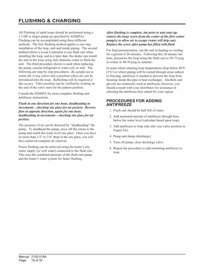
All Flushing of earth loops should be performed using a
1.5 HP or larger pump (as specified by IGSHPA).
Flushing can be accomplished using three different
methods. The first flushing method applies a one-step
installation of the loop, unit and inside piping. The second
method allows a Loop Contractor to use flush cart when
installing the loop, and at a later date, the dealer can install
the unit to the loop using only domestic water to flush the
unit. The third procedure shown is used when replacing
the pump, coaxial refrigerant to water coil, or unit. The
following are step-by-step procedures. Be careful not to
rotate the 3-way valves into a position where air can be
introduced into the loop. Reflushing will be required if
this occurs. Valve position can be verified by looking on
the end of the valve stem for the pattern position.
Consult the IGSHPA for more complete flushing and
antifreeze instructions.
Flush in one direction for one hour, deadheading in
increments - checking site glass for air pockets. Reverse
flow in opposite direction, again for one hour,
deadheading in increments - checking site glass for air
pockets.
The presence of air can be detected by “deadheading” the
pump. To deadhead the pump, close off the return to the
pump and watch the water level site glass. Once you have
no more than 1/2" to 3/4" drop in the site glass, you will
have achieved complete air removal.
Power flushing can be achieved using the home’s city
water supply (or well water) connected to the flush cart.
This uses the combined pressure of the flush cart pump
and the home’s water system for faster flushing.
After flushing is complete, but prior to unit start up,
remove the large screw from the center of the flow center
pump(s) to allow air to escape (water will drip out).
Replace the screw after pump has filled with fluid.
For final pressurization, run the unit in heating or cooling
for a period of 20 minutes. Following this 20 minute run
time, pressurize the loop using the flush cart to 50-75 psig
in winter or 40-50 psig in summer.
In areas where entering loop temperatures drop below 40°F
(5°C) or where piping will be routed through areas subject
to freezing, antifreeze is needed to prevent the loop from
freezing inside the pipe or heat exchanger. Alcohols and
glycols are commonly used as antifreeze, however, you
should consult with your distributor for assistance in
selecting the antifreeze best suited for your region.
PROCEDURES FOR ADDINGANTIFREEZE
1. Flush cart should be half full of water.
2. Add measured amount of antifreeze through hose
below the water level (calculate based upon loop).
3. Add antifreeze to loop side only (see valve position in
Figure 9A).
4. Pump and dump (discharge).
5. Turn off pump; close discharge valve.
6. Repeat the procedure to add remaining antifreeze to
loop.
FLUSHING & CHARGING

Manual 2100-518APage 19 of 30
SUPPLY
RETURN
MIS-2661
FLUSHING & CHARGING (CONTINUED)
FIGURE 8
CONNECTING FLUSH CART TO FLOW CENTER

Manual 2100-518APage 20 of 30
MIS-2662
FLUSH LOOP ONLY
FLUSH LOOP & UNIT TOGETHER
FLUSHING & CHARGING (CONTINUED)
FIGURES 9A & 9B
FLOW CENTER VALVE POSITIONING

Manual 2100-518APage 21 of 30
FLUSH UNIT ONLY
OPERATION
MIS-2663
FLUSHING & CHARGING (CONTINUED)
FIGURES 9C & 9D
FLOW CENTER VALVE POSITIONING

Manual 2100-518APage 22 of 30
FLUSHING & FILLING EARTH LOOP ANDUNIT(S) TOGETHER
All air and debris must be removed from the earth loop
piping system before operation. Flush the loop with a high
volume of water at a high velocity (2 fps in all piping in
accordance with IGSHPA guidelines).
1. Connect the unit and loop to the flow center.
2. Connect the flush cart hoses to the front port of the
flow center (see Figure 8).
3. Fill closed loop (outside) evenly with domestic water
and discharge the return water by adding water to the
flush cart until water returns to the reservoir. The
return water should be filtered or discharged to
remove debris.
4. Fill the flush cart two-thirds full for initial flushing.
5. Flush the lowest portion of the system first.
Depending upon the individual layout, this could be
the loop or the unit. (If unit is lowest part of system,
set valve position as shown in Figure 9C. If loop is
lowest part of system, set flow center valve position
as shown in Figure 9A.)
6. Restart the pump. Once you have a steady flow of
water on the return side from the system, deadhead
the pump by closing the ball valve on the hose
returning to the reservoir. This will generate the
maximum pressure on the system. While the return
ball valve is closed, note the fluid level in the
reservoir. If all the air is purged from the system, the
level will drop only 1/2" to 3/4" in the flush cart site
glass, since water is not compressible. This is the
only way to tell if the air is purged from the system.
Open valve quickly, wait one minute, then deadhead
again. Repeat this process until all air is purged from
the system.
7. Reverse the flow direction with the flush cart and
repeat Step #6.
8. Repeat Step #6 for the higher elevation side of the
system. (If unit is highest part of system, set valve
position as shown Figure 9C. If loop is highest part
of system, set flow center valve position as shown in
Figure 9A.)
9. After flushing both sides of the system, reset flow
control valves to flush the entire system. Set valve
position as shown in Figure 9B and repeat Step #7.
FLUSHING EARTH LOOP ONLY
1. Connect loop to flow center.
2. Connect the unit side connections of the flow center
together with a jumper hose.
3. Remove caps and plugs from flow center front access
ports.
4. Connect flush cart hoses to access ports.
5. Position valve stems as shown in Figure 9A.
6. Fill the flush cart two-thirds full for initial flushing.
7. Restart the pump. Once you have a steady flow of
water on the return side from the system, deadhead
the pump by closing the ball valve on the hose
returning to the reservoir. This will generate the
maximum pressure on the system. While the return
ball valve is closed, note the fluid level in the
reservoir. If all the air is purged from the system, the
level will drop only 1/2" to 3/4" in the flush cart site
glass, since water is not compressible. This is the
only way to tell if the air is purged from the system.
Open valve quickly, wait one minute, then deadhead
again. Repeat this process until all air is purged from
the system.
8. Reverse the flow direction with the flush cart and
repeat Step #7.
9. Rotate the flow center valves to isolate the flush cart
from the rest of the system (see Figure 9C).
10. Turn off flush cart pump, relieve pressure on the
hoses and remove them.
11. Replace flow center access plugs and caps.
12. Rotate valves back to position as shown in Figure 9B.
13. Remove jumper from unit connection ports.
FLUSHING & CHARGING (CONTINUED)

Manual 2100-518APage 23 of 30
FLUSHING UNIT ONLY (ALSO USEDWHEN REPLACING UNIT, COAXIALCOIL, HOSE KIT OR PUMP)
1. Connect unit to flow center.
2. Rotate 3-way valve to position shown in Figure 9C.
3. Remove access port caps and plugs and connect either
flush cart or Bard DORGHMT fitting (service only -
not intended for primary flush).
4. Attach garden hose to domestic water supply.
5. Purge air from garden hose before connecting to port
in flow center.
6. Attach another length of garden hose to the other port
in the flow center, leading to drain.
7. Flush flow center and unit with domestic water until
air is removed.
8. Close drain valve on discharge hose and pressurize
system to domestic water pressure (approx. 4-75
psig).
9. Remove bleed screw(s) from flow center pump
motors to purge air and replace screw(s).
10. Close valve on supply hose to trap pressure in the
system.
11. Rotate 3-way valves back to normal operating
position (see Figure 9D).
12. Remove water supply hose from flow center and
replace access port caps/plugs.
FLUSHING & CHARGING (CONTINUED)

Manual 2100-518APage 24 of 30
1. Check to make sure the loop and unit isolation valves
are completely open and the flush ports are closed and
sealed (see Figure 9D).
2. Geothermal units have two low pressure switches
installed. One switch is intended for Ground Water
Applications (default factory wired - blue wires), and
the second is intended for Ground Loop Applications
(yellow wires). Remove the “blue” wires from the
LPS terminals of the compressor control module
internal of the control panel of the geothermal heat
pump and replace with the yellow low pressure switch
wires (see unit wiring diagram).
3. Check and record the earth loop pressure (use P/T
ports at geothermal heat pump).
Loop Pressure_____IN_____OUT
4. Check and record flow rate.
FLOW RATE - _____GPM
5. Check performance of unit. (Refer to Geothermal
Heat Pump Installation Manual.)
PROCEDURE FOR PRESSURIZING THESYSTEM
1. Once system is completely flushed and antifreeze is
added, it can then be pressurized. Perform this by
deadheading the pump by closing the return hose ball
valve. This will increase the pressure on the loop via
the flush cart pump. As the pressure will fluctuate
with the seasons (set higher in winter and lower in
summer), it is suggested that the initial loop pressure
be 50-75 psig in winter and 40-50 psig in summer. If
you cannot reach these pressures with the flush cart
pump alone, turn on the fresh water feed to the cart
while still deadheading the pump. The potable water
pressure, along with the pump, will increase the
amount of pressure in the loop.
2. Bleed any air from the inside of the pump. This can
be done by removing the bleed screw from the center
of the pump motor head, allowing a small amount of
fluid to drip out. Replace the bleed screw.
3. Rotate the flow center valves to isolate the flush cart
from the rest of the system (see Figure 9D).
4. Turn off the flush cart pump, relieve the pressure on
the hoses and remove them.
5. Replace flow center access plugs and caps.
NOTE: If the flow center is mounted in the horizontal
position, the supply hose must be connected to the lower
flushing port to allow air to pass out of the upper port
during the final flushing.
PRESSURE/TEMPERATURE PLUGS
The pressure/temperature plugs (P/T plugs) supplied with
the ground water connectors are provided as a means of
measuring flow and temperature (see Figure 10). The
waterflow through the unit can be checked by measuring
the incoming water pressure at the supply pressure P/T
and subtracting the leaving water pressure at the return
water P/T plug. Comparing the differential to the
pressure drop/flow chart (Table 3) will determine the flow
rate through the heat pump.
Example: Model GV51S1 with a measured pressure
drop of 5.1 psig is equivalent to 9 GPM flow.
GPM rates higher than the required minimum flow rates
will not be detrimental to performance. However,
insufficient flow can significantly reduce capacity,
efficiency and create nuisance trips of safety controls, and
possibly damage to components in extreme conditions.
NOTE: Pressure/Temperature probes should be
lubricated with a water-based lubricant prior to gently
pushing the probes into the P/T ports to prevent internal
damage. Thermometers, probes and gauges are available
for conducting these tests.
FLOW CENTER INITIAL STARTUP

Manual 2100-518APage 25 of 30
10
120
110
100
90
80
706050
40
30
20
0
Retaining cap, hand tighten only
Pete's test plug
Test plug cap
Barbed 90° adapter
MIS-2622 A
NOTE: Slide retaining cap back to exposedouble o-rings. Apply petroleum jelly to o-ringsto prevent damage and aid in insertion
with guage adaptorDial face pressure guage
Thermometer
ledoM
MPG
1S72VG 1S15VG/1S83VG 1S16VG 1S17VG
DISP .dH.tF DISP .dH.tF DISP .dH.tF DISP .dH.tF
3 1.0 32.0
4 5.0 51.1 9.0 80.2
5 2.1 77.2 4.1 32.3
6 7.1 29.3 3.2 13.5
7 3.2 13.5 2.3 83.7 2 16.4
8 1.3 51.7 1.4 64.9 5.2 77.5 2 16.4
9 1.4 64.9 1.5 77.11 2.3 83.7 4.2 45.5
01 1.6 70.41 9.3 00.9 8.2 64.6
11 1.7 83.61 7.4 48.01 4.3 48.7
21 2.8 29.81 5.5 96.21 9.3 00.9
31 4.9 96.12 4.6 67.41 5.4 83.01
41 6.01 54.42 3.7 48.61 2.5 00.21
51 1.8 96.81 9.5 16.31
61 9 67.02 7.6 64.51
71 9.9 48.22 4.7 70.71
81 4.8 83.91
FIGURE 10
PRESSURE TEMPERATURE PORTS
TABLE 3A
GV SERIES COIL PRESSURE DROP
P/T

Manual 2100-518APage 26 of 30
TABLE 3B
GT SERIES COIL PRESSURE DROP
TABLE 3C
QW SERIES COIL PRESSURE DROP
ledoM
MPG
1S63CTG 1S84CTG 1S06CTG
DISP .dH.tF DISP .dH.tF DISP .dH.tF
3 1.0 32.0
4 5.0 51.1 9.0 80.2
5 2.1 77.2 4.1 32.3
6 7.1 29.3 3.2 13.5
7 3.2 13.5 2.3 83.7 2 16.4
8 1.3 51.7 1.4 64.9 5.2 77.5
9 1.4 64.9 1.5 77.11 2.3 83.7
01 1.6 70.41 9.3 00.9
11 1.7 83.61 7.4 48.01
21 2.8 29.81 5.5 96.21
31 4.9 96.12 4.6 67.41
41 6.01 54.42 3.7 48.61
51 1.8 96.81
61 9 67.02
71 9.9 48.22
81
MPG
&1S2WQ1S3WQ 1S4WQ 1S6WQ
GISP .dH.tF GISP .dH.tF GISP .dH.tF
3 1.0 32.0
4 5.0 51.1 9.0 80.2
5 2.1 77.2 4.1 32.3
6 7.1 29.3 3.2 13.5
7 3.2 13.5 2.3 83.7 2 16.4
8 1.3 51.7 1.4 64.9 5.2 77.5
9 1.4 64.9 1.5 77.11 2.3 83.7
01 1.6 70.41 9.3 00.9
11 1.7 83.61 7.4 48.01
21 2.8 29.81 5.5 96.21
31 4.9 96.12 4.6 67.41
41 6.01 54.42 3.7 48.61
51 1.8 96.81
61 9 67.02
71 9.9 48.22
81

Manual 2100-518APage 27 of 30
melborP sesuaCelbissoP snoitcerroC&skcehC
tuOspirDretaWnoitasnednoC .spagnoitalusnirofkcehc,gnipipetalusnI
kaeLretaW .sgnittifnethgit/tcepsnI
wolFoN/wolFwoL
ssoLrewoP .pmuptaehehtmorfylppusrewopkcehC
rekaerBtiucriCnwolB .xoblortnocpmuptaehniretnecwolfrofrekaerbtiucricteseR
seriWesooLronekorB .seriwnethgitroecalpeR
kcutStfahSpmuP .gnitatorsitfahstahterusnednagulpnoitacidniehtevomeR
kcoLriA .riaetanimileotpoolhsulF
pmuPdeziSylreporpmI .yticapacpmupddA
pmuPevitcefeD .ecalpeR
erusserPevitisoPoN .ezirusserpdnaderiuqersahsulf,diulfdda,skaelrofkcehC
noituloSsuocsiV .ezeerfitnafoepytegnahC
nezorFrognizeerFpooL.erutarepmetremrawtasevorpmiwolffieesotnoitarepoC/AottatsomrehthctiwS
.noitcetorpezeerferusaemdnaezeerfitnaddA
pooLnikniK .ecalpeRronethgiartS
yesioN
pmuPevitcefeD .ecalpeR
pooLniriA .niagapoolhsulF
noitarbiV .gnitnuomkcehC
ssoLerusserP
kaeL .riapeR
egnahCerutarepmeT .segnahcerutarepmetsayravdluohserusserp;melborpatoN
noisnapxEepiP .gnixalergnipipcitsalp;melborpatoN
notuOspirTtinUwolFretaW
roerusserPwoL()erusserPhgiH
wolFoN/wolFwoL .wolFoN/wolFwoLeeS
TROUBLESHOOTING
Manual 2100-518APage 28 of 30
Selection of antifreeze solutions for ground loop
applications requires consideration of many important
factors, which may have long-term implications in regards
to performance and system component life. Each area of
concern leads to a different antifreeze solution. The fact
that there is no “ideal” antifreeze and any choice will
require compromises in one area or another. Some of these
considering factors include:
Safety – The toxicity and flammability of the
antifreeze solution.
Thermal Performance – The heat transfer and
viscosity effects of the antifreeze.
Cost – The prices vary widely.
Corrosiveness – System materials must be compatible
with the antifreeze solution.
Stability – Will the solution require periodic change
out or maintenance?
Convenience – Is the solution readily available and
easy to transport and install?
Codes – Will the solution meet local/regional/state/
national regulatory standards?
It is highly recommended to utilize pre-mixed antifreeze
solutions where possible to alleviate many installation
problems and extra labor.
The following are some general observations about the
types of antifreeze materials presently being applied in the
geothermal ground loop markets:
Methanol – Considered toxic in pure form, good heat
transfer, low to mid-price, flammable in concentrations
greater than 25%, non-corrosive and low viscosity.
Methanol has delivered outstanding performance in ground
loop applications for over 20 years. Its only drawbacks are
toxicity and flammability. Although methanol enjoys
widespread consumer use as windshield washer fluid in
even higher concentrations, some local codes may limit its
use in ground loops. (Note: Do NOT use automotive
windshield washer fluid as antifreeze. Most washer fluids
contain chemicals that will cause foaming.) To increase
safety, a pre-mixed form should be used on the jobsite to
increase the safety factor. Pure methanol can be purchased
from any chemical supplier.
Ethanol – Good heat transfer (lower than methanol),
high price, flammable in concentrations greater than 10%,
non-corrosive and low viscosity. Ethanol in pure form is
considered non-toxic and shows promise as a geothermal
heat transfer fluid. However, the U.S. Bureau of Alcohol,
Tobacco & Firearms (ATF) limit its distribution. All non-
beverage ethanol is required to be denatured and rendered
unfit to drink. Generally, this is done by adding a small
percentage of toxic substances such as methanol, benzene
or gasoline as a denaturant. Many of the denaturants are
difficult to identify by the casual user, and many are not
compatible with polyethylene pipe. Only denatured
ethanol can be purchased for commercial use. The use of
ethanol is not recommended because of the unknown
denaturants included in the solution and their possible
toxicity and damage resulting to polyethylene piping
systems. Denaturing agents that are petroleum based can
damage polyethylene pipe.
ANTIFREEZE SELECTION & USE

Manual 2100-518APage 29 of 30
Propylene Glycol – Non-toxic, non-corrosive,
expensive, hard to handle when cold, poorest heat transfer,
has formed “slime-type” coatings inside system piping.
Propylene Glycol is acceptable in systems anticipating loop
temperatures no colder than 40°F (4.4°C). These systems
typically use antifreeze because of low ambient conditions
(outside plumbing or cooling tower, etc.). When loop
temperatures are below 40°F, the fluid becomes very
difficult to pump and heat transfer characteristics suffer
greatly. Only food grade propylene glycol is recommended
to prevent the corrosion inhibitors from reacting with local
water causing “slime-type” coatings inside heat
exchangers. If propylene glycol must be used (code
requirements), careful consideration of loop Reynolds
numbers, pump selection and pressure drop must be
considered.
Potassium Acetate (GS4) – Non-toxic, good heat
transfer, high price, non-corrosive with added inhibitors,
low viscosity. Due to its low surface tension, Potassium
Acetate has been known to leak through mechanical
fittings and certain thread sealants. A variant of the salt
family, it can be extremely corrosive when exposed to air.
Potassium Acetate is not recommended in ground loop
applications due to the leaking and (ultimately) corrosion
problems associated with it.
NOTE: Consult with your local distributor if you have
questions regarding antifreeze selection and any comments
to report about problems or success with any particular
methods in your area.
EPYT EZISEMULOV
)EPIP'001/NOLLAG.S.U(EMULOV
)SRETEM01/SRETIL(
reppoC STC"1 1.4 5.51
reppoC STC"4/1-1 4.6 2.42
reppoC STC"2/1-1 2.9 8.43
enelyhteyloP 11RDSSPI-"4/3 0.3 4.11
enelyhteyloP 11RDSSPI-"1 7.4 8.71
enelyhteyloP 11RDSSPI-"4/1-1 5.7 4.82
enelyhteyloP 11RDSSPI-"2/1-1 8.9 1.73
enelyhteyloP 11RDSSPI-"2 4.51 3.85
EPYTNOITCETORPEZEERFROFERUTAREPMETMUMINIM
)C°2.21-(F°01 )C°4.9-(F°51 )C°7.6-(F°02 )C°9.3-(F°52
lonahteM %52 %12 %61 %01
*lonahtE %92 %52 %02 %41
PSU%001edarGdooF
locylGenelyporP%72 %42 %02 %31
ANTIFREEZE SELECTION & USE (CONTINUED)
TABLE 4
FLUID VOLUME
TABLE 5
PERCENTAGES BY VOLUME
Approximate Fluid Volume per 100’ (10 Meters) of Pipe
Antifreeze Percentages by Volume
* Must not be denatured with any petroleum based product.

Manual 2100-518APage 30 of 30
ANTIFREEZE VERIFICATION
Both Glycol and Alcohol based antifreeze solutions can be
verified to the specific percentage of volume within the
ground loop system. One of the easiest ways to check this
is through use of a Hydrometer to check the specific
density of the ground loop fluid and comparing these to the
charts supplied by the antifreeze manufacturer (see Figure
11).
Hydrometers can be purchased from your local distributor
and are also available through national wholesalers.
MIS-2666
WARNINGAlways use properly marked vehicles (D.O.T.
placards) and clean/suitable/properly marked
identified containers for handling flammable
antifreeze mixtures. Post and advise those
on the jobsite of chemical use and potential
dangers of handling and storage.
CAUTIONAlways obtain MSDS (material safety data
sheets) for all chemicals used in ground loop
applications - including chemicals used as
antifreeze.
FIGURE 11
DENSITY VERIFICATION
for SOLUTION STRENGTH
TABLE 6 TABLE 7
It is recommended that IGSHPA design and specifications are utilized for Loop Design, Pipe Manifolding and Hot Fusion
operations.
There are many available software programs available to aid with loop design parameters. Your local loop material or
equipment supplier may have this technology available. Technical Service has the capability to assist you in this area as well,
but it is on a first come - first serve basis.