installation and maintenance of slewing ring …naflic.co.uk/pdfs/sr installation instructions...
TRANSCRIPT

NBC Group Ltd www.nbcgroup.co.uk Slewing ring installation & maintenance Version: November 2011
Orleton Lane; Wellington, Telford; TF1 2BG; Shropshire; England
INSTALLATION AND MAINTENANCE
OF SLEWING RING BEARINGS
NBC Group Ltd www.nbcgroup.co.uk Slewing ring installation & maintenance Version: November 2011
Transport, handling and storage
Slewing rings must be handled, transported and stored in a horizontal position or on specially built
incline cradles that support the ring structure appropriately. Any ovality so developed must be
removed during installation.
Large slewing rings usually have lifting holes for eye‐bolts to assist lifting in the inner and outer rings.
Please check the weight of the ring to ensure slings and/or chains are of sufficient capacity!
Shock loads, especially in the radial direction, must be avoided as this may damage the raceways.
If stacked on a pallet then care must be taken not to dislodge seal strips or grease fittings during
movement. Wooden or rubber spacers would be of benefit between each bearing. External gear
teeth (especially) should be protected from any impact damage.
As supplied slewing rings are generally packed for storage in a covered store and for a period not
exceeding 6 months. Light surface corrosion can usually be removed from exterior surfaces – and it
is more important that the raceways are well greased and rust free. Standard commercial solvents
can be used to degrease the slewing ring if necessary.
In extreme cases after long term storage bearings may need professionally reconditioning before
installation.
When unwrapping, care must be taken not to cut and damage the integral seals.
NBC Group Ltd www.nbcgroup.co.uk Slewing ring installation & maintenance Version: November 2011
Supporting surfaces
The supporting surfaces must have a flat machined surface and be
rigid enough to eliminate torsional buckling under load that would
affect the smooth operation of the slewing ring.
The thickness of the supporting plates should be no less than that
indicated below – which is offered as a rough approximation only!
Definitive results are best achieved with Finite Element Analysis.
Raceway dia (mm) 500 750 1000 1250 1500 2000 2500 3000
Min. Support Thickness (mm) 25 30 35 40 50 60 70 80
The width of the supporting surface must at least be equal to the width of the ring it supports.
The flatness defects under load must not exceed the values indicated below to avoid tight spots or
seizure; both of which will reduce slewing ring bearing service life.
Raceway dia (mm) 500 750 1000 1250 1500 2000 2500 3000
Max. allowable flatness defect (mm)
Single row ball bearings 0.12 0.18 0.21 0.25 0.28 0.33 0.38 0.42
Max. allowable flatness defect (mm)
X‐Roller or double row ball bearings 0.10 0.12 0.15 0.18 0.20 0.25 0.29 0.32
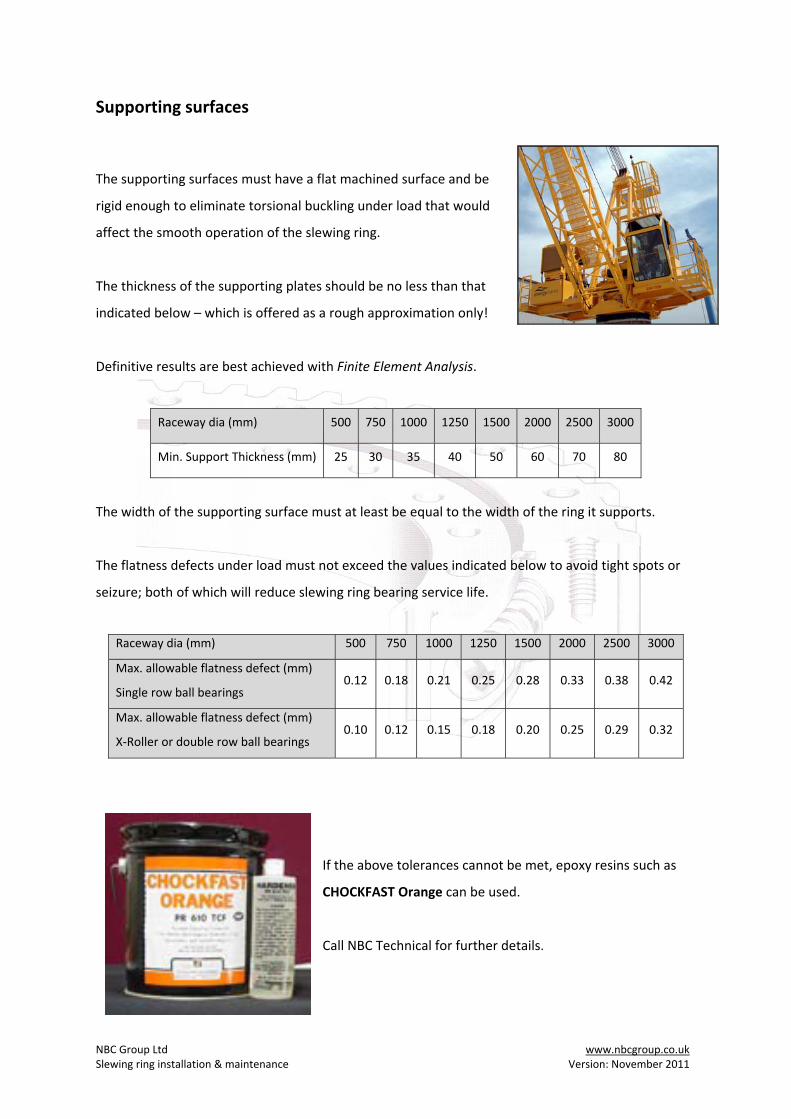
If the above tolerances cannot be met, epoxy resins such as
CHOCKFAST Orange can be used.
Call NBC Technical for further details.
NBC Group Ltd www.nbcgroup.co.uk Slewing ring installation & maintenance Version: November 2011
Circularity of the slewing ring
In the event of high radial loads, then the circularity of the slewing ring may be affected. If circularity
cannot be maintained by use of the machined step on at least one of the machined diameters of the
bearing, then a number of dowel pins through the rings might be considered.
Please consult with NBC Technical for approval of this before drilling – or you will negate the
manufacturer’s warranty.
The general tolerance for pilot and spigot diameters according to ISO 286‐2 are:‐
Diameter
(mm)
180‐
250
251‐
315
316‐
400
401‐
500
501‐
630
631‐
800
801‐
1000
1001‐
1250
1251‐
1600
1601‐
2000
2001‐
2500
2501‐
3150
Pilot H9
(micron) +115 +130 +140 +155 +175 +200 +230 +260 +310 +370 3440 +540
Spigot f9
(micron)
‐50
‐165
‐56
‐185
‐62
‐202
‐68
‐223
‐76
‐251
‐80
‐280
‐86
‐316
‐98
‐358
‐110
‐420
‐120
‐490
‐130
‐570
‐145
‐685
Orientation of the slewing ring
Most slewing rings have a “filling plug” either on the inner diameter or outer diameter face. Double
row bearings have 2 filling plugs, usually at 180 degrees. The filling plug is normally machined in the
same place as the start/finish of the hardening path (these should never overlap) as this is a zone of
softness.
The filler plug should always be placed at the point of minimum strain (for example at right angles to
the main load axis). In some cases the bolt pattern will be asymmetric to force this orientation.
NBC Group Ltd www.nbcgroup.co.uk Slewing ring installation & maintenance Version: November 2011
Gear eccentricity
The point of maximum eccentricity of a geared slewing ring will be marked by the manufacturer,
usually with green or red paint covering 2 or 3 teeth. This is the point at which the backlash must be
set.
Remember to use this point of maximum eccentricity to set all pinions in the case of multiple drive
systems.
The matching pinion should have a minimum clearance of 0.03 ‐ 0.05mm x gear module.
The system should be rotated a few times to check gear mesh (across the whole tooth face) before
lubrication.
Seal Strip
Seal strip is usually specific to each manufacturer and the profiles and groove dimensions vary.
Seals must be inspected at least annually and replaced as required. Standard nitrile seals will perish
in approximately 5 years, VITON seals (usually reserved for high temperature applications) should
last slightly longer.
A competent supplier should be able to offer replacement seal strip from stock as required.
Module Module Module
4 10 18
5 12 20
6 14 22
8 16 240.24 ‐ 0.32 mm
0.18 ‐ 0.24 mm
0.72 ‐ 0.96 mm
0.66 ‐ 0.88 mm
Normal backlash Normal backlash Normal backlash
0.15 ‐ 0.20 mm
0.12 ‐ 0.16 mm
0.48 ‐ 0.64 mm
0.42 ‐ 0.56 mm
0.36 ‐ 0.48 mm
0.30 ‐ 0.40 mm
0.60 ‐ 0.80 mm
0.54 ‐ 0.72 mm
NBC Group Ltd www.nbcgroup.co.uk Slewing ring installation & maintenance Version: November 2011
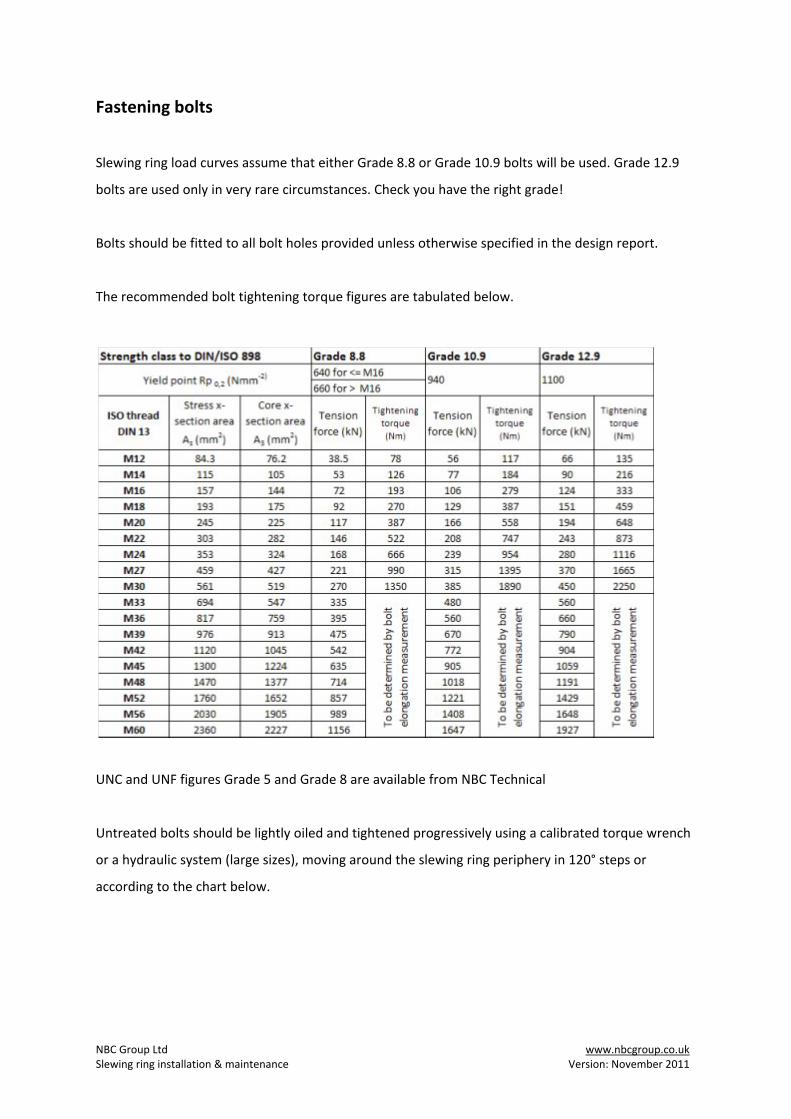
Fastening bolts
Slewing ring load curves assume that either Grade 8.8 or Grade 10.9 bolts will be used. Grade 12.9
bolts are used only in very rare circumstances. Check you have the right grade!
Bolts should be fitted to all bolt holes provided unless otherwise specified in the design report.
The recommended bolt tightening torque figures are tabulated below.
UNC and UNF figures Grade 5 and Grade 8 are available from NBC Technical
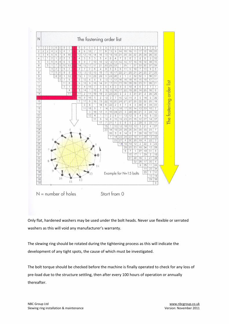
Untreated bolts should be lightly oiled and tightened progressively using a calibrated torque wrench
or a hydraulic system (large sizes), moving around the slewing ring periphery in 120° steps or
according to the chart below.
NBC Group Ltd www.nbcgroup.co.uk Slewing ring installation & maintenance Version: November 2011
Only flat, hardened washers may be used under the bolt heads. Never use flexible or serrated
washers as this will void any manufacturer’s warranty.
The slewing ring should be rotated during the tightening process as this will indicate the
development of any tight spots, the cause of which must be investigated.
The bolt torque should be checked before the machine is finally operated to check for any loss of
pre‐load due to the structure settling, then after every 100 hours of operation or annually
thereafter.
NBC Group Ltd www.nbcgroup.co.uk Slewing ring installation & maintenance Version: November 2011
Slewing rings should never be fixed by welding, nor should welding processes be carried out nearby.
Care must be taken not to earth through the slewing ring as this may damage the raceways
permanently.
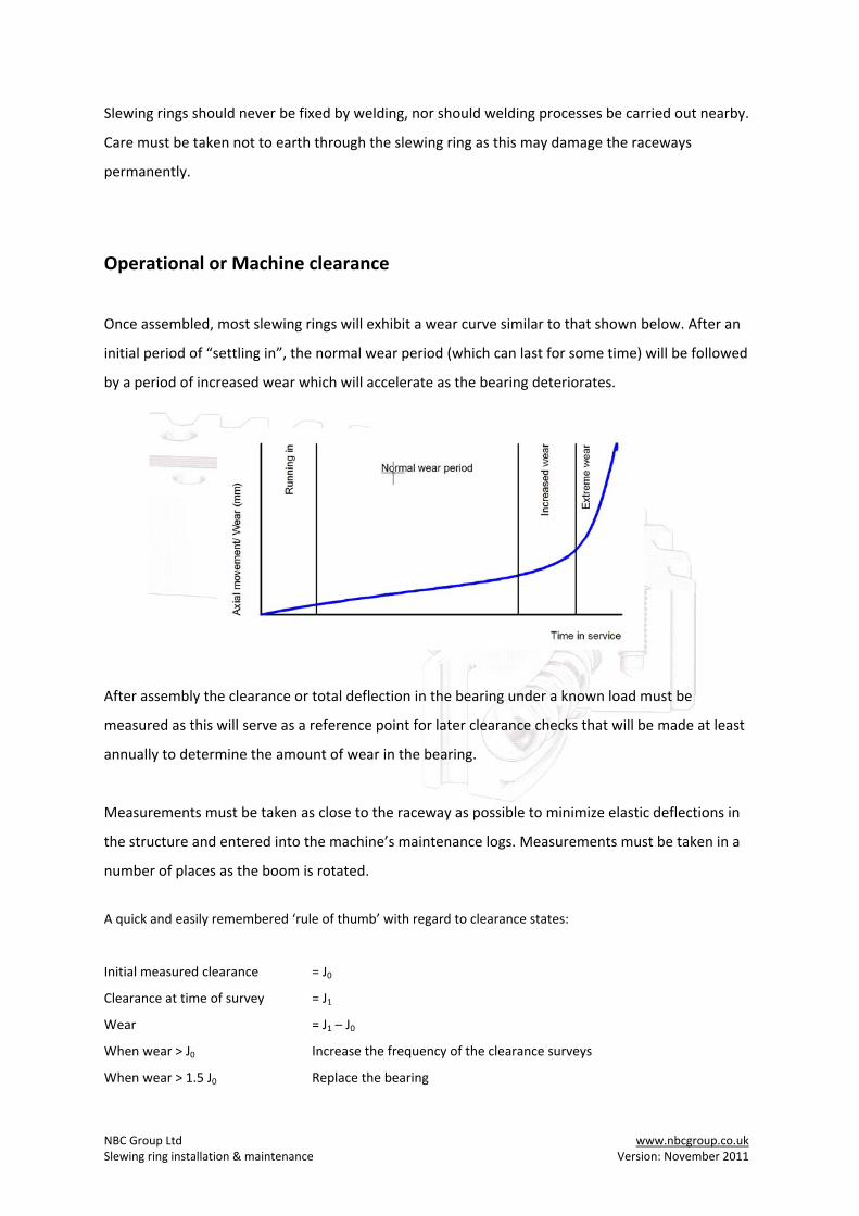
Operational or Machine clearance
Once assembled, most slewing rings will exhibit a wear curve similar to that shown below. After an
initial period of “settling in”, the normal wear period (which can last for some time) will be followed
by a period of increased wear which will accelerate as the bearing deteriorates.
After assembly the clearance or total deflection in the bearing under a known load must be
measured as this will serve as a reference point for later clearance checks that will be made at least
annually to determine the amount of wear in the bearing.
Measurements must be taken as close to the raceway as possible to minimize elastic deflections in
the structure and entered into the machine’s maintenance logs. Measurements must be taken in a
number of places as the boom is rotated.
A quick and easily remembered ‘rule of thumb’ with regard to clearance states:
Initial measured clearance = J0
Clearance at time of survey = J1
Wear = J1 – J0
When wear > J0 Increase the frequency of the clearance surveys
When wear > 1.5 J0 Replace the bearing

NBC Group Ltd www.nbcgroup.co.uk Slewing ring installation & maintenance Version: November 2011
More specifically, and for larger bearings, Roth Erde list the following information
Table 1: Permissible increase in bearing clearance for single row ball bearings
Track dia (mm) Ball diameter (mm)
20 25 30 35 40
< 1000 1.4 1.4 1.5 1.7 1.9
< 1250 1.5 1.6 1.7 2.0
< 1500 1.6 1.7 1.7 2.0
< 1750 1.7 1.8 2.1
< 2000 1.8 1.9 2.2
Table 2: Permissible increase in bearing clearance for double row ball bearings
Track dia (mm) Ball diameter (mm)
20 25 30 35 40
< 1000 1.8 1.9 2.0 2.1 2.5
< 1250 1.9 2.0 2.1 2.2 2.6
< 1500 2.0 2.1 2.2 2.3 2.7
< 1750 2.2 2.3 2.4 2.8
< 2000 2.3 2.4 2.5 2.9
Table 3: Permissible increase in bearing clearance for single row roller bearings
Track dia (mm) Ball diameter (mm)
20 25 32 40 45
< 500 0.22 0.24 0.28
< 800 0.27 0.29 0.33 0.38
< 1000 0.30 0.34 0.38 0.43 0.46
< 1500 0.50 0.54 0.58 0.63 0.66
< 2000 0.62 0.64 0.68 0.73 0.76
NOTE: Legal requirements pertaining to specific machines may override this data.
NBC Group Ltd www.nbcgroup.co.uk Slewing ring installation & maintenance Version: November 2011
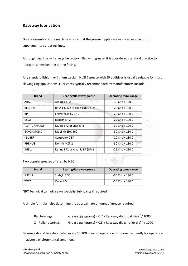
Raceway lubrication
During assembly of the machine ensure that the grease nipples are easily accessible or run
supplementary greasing lines.
Although bearings will always be factory filled with grease, it is considered standard practice to
lubricate a new bearing during fitting.
Any standard lithium or lithium calcium NLGI 2 grease with EP additives is usually suitable for most
slewing ring applications. Lubricants typically recommended by manufacturers include:‐
Brand Bearing/Raceway grease Operating temp range
ARAL Aralub HLP2 ‐30 C to + 120 C
BECHEM Rhus L474/2 or High‐Lub L 2 EP ‐20 C to + 120 C
BP Energrease LS‐EP 2 ‐20 C to + 120 C
ESSO Beacon EP 2 ‐20 C to + 120 C
TOTAL FINA ELF Multis EP2 or Lical EP2 ‐30 C to + 120 C
EXXONMOBIL Mobilith SHC 460 ‐30 C to + 130 C
KLUBER Centoplex 2 EP ‐20 C to + 130 C
RHENUS Norlith MZP 2 ‐30 C to + 130 C
SHELL Retina EP2 or Alvania EP (LF) 2 ‐25 C to + 130 C
Two popular greases offered by NBC
Brand Bearing/Raceway grease Operating temp range
FUCHS Stabyl LT 50 ‐50 C to + 130 C
TOTAL Ceran HV ‐25 C to + 180 C
NBC Technical can advise on specialist lubricants if required.
A simple formula helps determine the approximate amount of grease required
Ball bearings Grease qty (grams) = 0.7 x Raceway dia x (ball dia) 2 / 1000
X ‐ Roller bearings Grease qty (grams) = 0.5 x Raceway dia x (roller dia) 2 / 1000
Bearings should be relubricated every 50‐100 hours of operation but more frequently for operation
in adverse environmental conditions.
NBC Group Ltd www.nbcgroup.co.uk Slewing ring installation & maintenance Version: November 2011
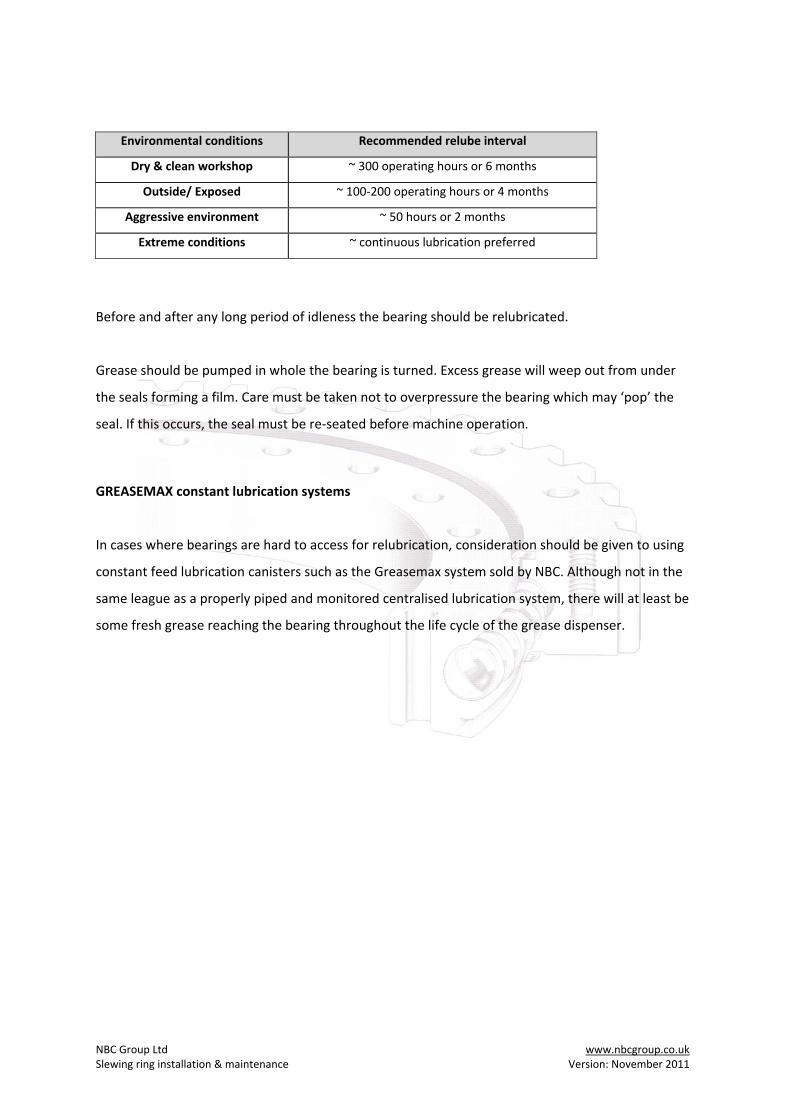
Environmental conditions Recommended relube interval
Dry & clean workshop ~ 300 operating hours or 6 months
Outside/ Exposed ~ 100‐200 operating hours or 4 months
Aggressive environment ~ 50 hours or 2 months
Extreme conditions ~ continuous lubrication preferred
Before and after any long period of idleness the bearing should be relubricated.
Grease should be pumped in whole the bearing is turned. Excess grease will weep out from under
the seals forming a film. Care must be taken not to overpressure the bearing which may ‘pop’ the
seal. If this occurs, the seal must be re‐seated before machine operation.
GREASEMAX constant lubrication systems
In cases where bearings are hard to access for relubrication, consideration should be given to using
constant feed lubrication canisters such as the Greasemax system sold by NBC. Although not in the
same league as a properly piped and monitored centralised lubrication system, there will at least be
some fresh grease reaching the bearing throughout the life cycle of the grease dispenser.
NBC Group Ltd www.nbcgroup.co.uk Slewing ring installation & maintenance Version: November 2011
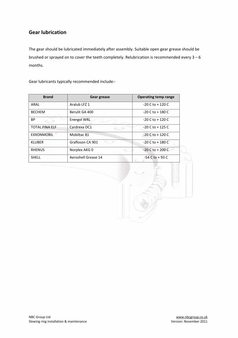
Gear lubrication
The gear should be lubricated immediately after assembly. Suitable open gear grease should be
brushed or sprayed on to cover the teeth completely. Relubrication is recommended every 3 – 6
months.
Gear lubricants typically recommended include:‐
Brand Gear grease Operating temp range
ARAL Aralub LFZ 1 ‐20 C to + 120 C
BECHEM Berulit GA 400 ‐20 C to + 180 C
BP Energol WRL ‐20 C to + 120 C
TOTAL FINA ELF Cardrexa DC1 ‐20 C to + 125 C
EXXONMOBIL Mobiltac 81 ‐20 C to + 120 C
KLUBER Grafloson CA 901 ‐20 C to + 180 C
RHENUS Norplex AKG 0 ‐20 C to + 200 C
SHELL Aeroshell Grease 14 ‐54 C to + 93 C