
17. Slab rebar arrangement
1) Slab rebar arrangementSlab type classification
2-way slab rebar arrangement method 1-way slab rebar arrangement method
Slab main bar arrangement type classification
Bent bar type
- Union type of outer beam and slab
- Union type of outer wall and slab
(ly < 2lx Type) (ly < 2lx Type)main block main block
90°standardhook
wall
0.3L or 0.3L1
0.3L or 0.3L1 0.3L or 0.3L1
apply A class splice of tension bar if upper part bar tying onlocation (apply B class splice of tension bar on the rest location)
apply A class splice of tension bar if upper part bar tying onlocation (apply B class splice of tension bar on the rest location)
big value
big value big value
big value
0.3L or 0.3L1

ⓑ Cut bar type
- Union type of outer beam and slab
- Union type of outer wall and slab
90°standardhook
wall
0.3L or 0.3L1
0.3L or 0.3L1 0.3L or 0.3L1
apply A class splice of tension bar if upper part bar tying onlocation (apply B class splice of tension bar on the rest location)
apply A class splice of tension bar if upper part bar tying onlocation (apply B class splice of tension bar on the rest location)
big value
big value big value
big value
0.3L or 0.3L1

③ Rebar arrangement details of slab stepped pulley
In case H < 75mm or t/4
In case t/4 < H < t and H < 150
In case t < H < 2t
※ In case H > 2t, consult with structure planner.
※ In case there are stepped pulley on slab center part, you should fix by using 90°standard hook for slab lower part rebar.
④ Slab and wall union details
splice length of tension bar
1-HD13 or over main bar
slab arrangement distanceusing closed type STR
4-HD13 or over main bar
splice length of tension bar
standard hook
standard hook
H≤75mm or t/4
outside inside
wall slab
90st
anda
rd h
ook

⑤ Tolerance range of slab , beam , pillar , wall rebar arrangement
ⓐ Allow to 6mm as tolerance of D in case under 600mm of slab, beam, pillar,
wall.
Allow to 10mm as tolerance of D in case over 600mm of slab, beam, pillar,
wall.
ⓑ Allow to 50mm as tolerance in case bent point or end point of length
direction rebar(but, except for end of concrete)
ⓒ Big bar of pillar and stirrup of beam can get the space till 0~6mm as space
length from main bar
cove
r thi
ckne
ss
cove
r thi
ckne
ss
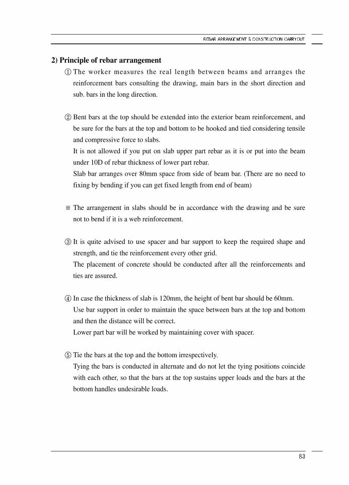
2) Principle of rebar arrangement① The worker measures the real length between beams and arranges the
reinforcement bars consulting the drawing, main bars in the short direction and
sub. bars in the long direction.
② Bent bars at the top should be extended into the exterior beam reinforcement, and
be sure for the bars at the top and bottom to be hooked and tied considering tensile
and compressive force to slabs.
It is not allowed if you put on slab upper part rebar as it is or put into the beam
under 10D of rebar thickness of lower part rebar.
Slab bar arranges over 80mm space from side of beam bar. (There are no need to
fixing by bending if you can get fixed length from end of beam)
※ The arrangement in slabs should be in accordance with the drawing and be sure
not to bend if it is a web reinforcement.
③ It is quite advised to use spacer and bar support to keep the required shape and
strength, and tie the reinforcement every other grid.
The placement of concrete should be conducted after all the reinforcements and
ties are assured.
④ In case the thickness of slab is 120mm, the height of bent bar should be 60mm.
Use bar support in order to maintain the space between bars at the top and bottom
and then the distance will be correct.
Lower part bar will be worked by maintaining cover with spacer.
⑤ Tie the bars at the top and the bottom irrespectively.
Tying the bars is conducted in alternate and do not let the tying positions coincide
with each other, so that the bars at the top sustains upper loads and the bars at the
bottom handles undesirable loads.

3) Calculation of slab plateIt is wrong method in case you cut the length of cut bar(top point) in advance by
calculating point from center to center of beam.
Therefore, you determine the end by calculating as the criterion of short LX from
the rest plate by deducting both width parts.
※ When bending in slab, using the hunch former will enhance the accuracy and
workability.
Hunch former can be made with bars on construction site.
If the bar is bent with hands, the length and the height of hunch will different
whenever it is made.
Please work with hunch former because bent bar decline to left/right side if you
bending too slantly to fit the height with hunch angle 45°.
L calculate end
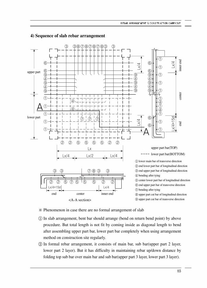
4) Sequence of slab rebar arrangement
※ Phenomenon in case there are no formal arrangement of slab
① In slab arrangement, bent bar should arrange (bend on return bend point) by above
procedure. But total length is not fit by coming inside as diagonal length to bend
after assembling upper part bar, lower part bar completely when using arrangement
method on construction site regularly.
② In formal rebar arrangement, it consists of main bar, sub bar(upper part 2 layer,
lower part 2 layer). But it has difficulty in maintaining rebar up/down distance by
folding top sub bar over main bar and sub bar(upper part 3 layer, lower part 3 layer).
<A-A section>
① lower main bar of transverse direction
② end lower part bar of longitudinal direction
③ end upper part bar of longitudinal direction
④ bending after tying
⑤ center lower part bar of longitudinal direction
⑥ end upper part bar of transverse direction
⑦ bending after tying
⑧ upper part cut bar of longitudinal direction
⑨ upper part cut bar of transverse direction
upper part bar(TOP)
lower part bar(BOTTOM)
inne
r end
upper part
lower part
end inner endcenter
cent
eren
d

5) Sequence of base slab rebar arrangement
※ Arrange the bars in numerical order suggested above.
※ Use spacer and bar support to install within 1m each transverse & longitudinal
direction for upper & lower part rebar and also install to 1st rebar for each end.
<A-A section>
Lx/4Lx/4 Lx/2inner endend center
Lx/4Lx/4 Lx/2Lx
Lx/4
Lx/4
① lower main bar of transverse direction(end center part)
② center lower part bar of longitudinal direction(center part)
③ tying bent bar of longitudinal direction④ center upper part bar of longitudinal direction⑤ tying bent bar of transverse direction
tying bent bar of longitudinal direction(bend opposite side after tying)
⑥ end lower part bar of longitudinal direction bending bent bar of transverse direction(bend opposite side after tying)
⑦ end upper part bar of longitudinal direction⑧ center upper part bar of transverse direction⑨ end upper part bar of transverse direction
upper part bar
lower part bar
underground tiebeam obtains thecover thickness over 80mm for
arrangement of slab lower part bar
inne
r end
cent
eren
d
fixed length of tension barwhich has standard hook
6) Check after assembling slabAfter construction of slabs, the supervisor should check following matters.
① Are pillars of adjacent floor(usually upper floor) well positioned having intended
dimensions?
② Is cover depth of slab well distributed and balanced?
③ Is there any abnormally inclined bent bar?
④ Are spacer and bar support rightly installed to be strong bar splice all right?
⑤ Is slab Bar splice all right?
⑥ Is reinforcement at the opening acceptable?
⑦ Enough splice length to the next floor?
Any dissatisfaction with items above will lead to poor construction and safety
problems.
In particular, if it is the matter of columns, it is very difficult to rebuild it and has poor
appearances.
And it is also an economical burden to the builder.
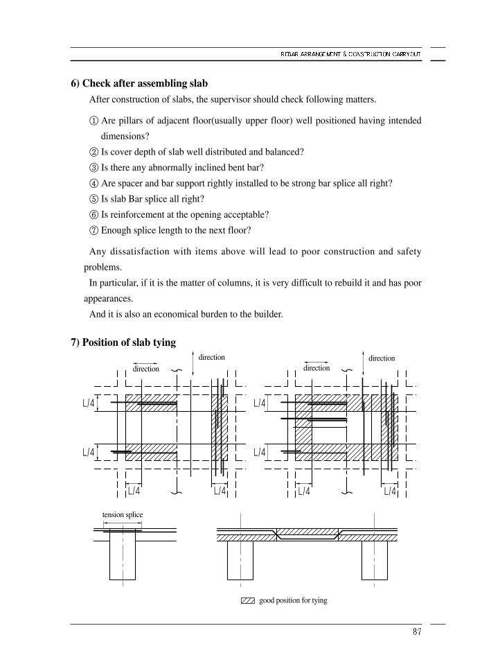
7) Position of slab tying
direction directiondirection direction
tension splice
good position for tying

8) Understanding of slab drawing
① If all bottom of slab symbol is different per span, rebar arranged to main bar
direction for short side. If span will be reverse direction, you should check in
advance because main bar will be reverse direction. (especially in case slab
stepped pulley)
In the plane drawing of open part, you can see the inside as above when you see to
arrow direction with dotted line and also you can know in detail with chart about the
size of beam and also which rebar will be installed.
Especially, you should check section drawing well.
If you cut plane, you can see elevation(verticality), reversely if you cut elevation, you
can see plane.
In any drawing and plane, we mark section for the part to understand difficultly to
help you for processing and arrangement on right section of drawing.
It is best way to get the training of supervisor and you must study symbols on
drawings.
down 200mm to right side fromleft side of solid line
open part plane figure
plane section
cross section
SLAB DOWN
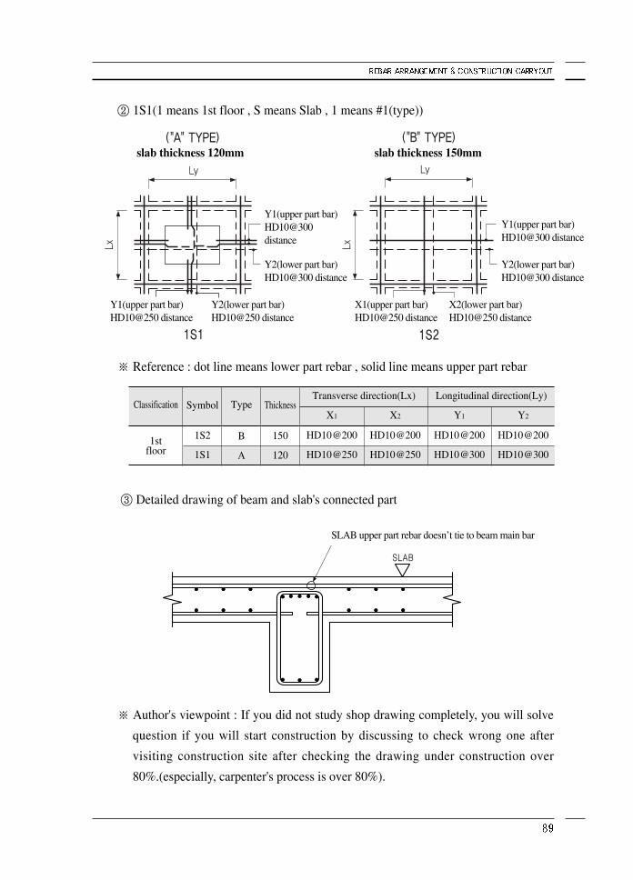
② 1S1(1 means 1st floor , S means Slab , 1 means #1(type))
※ Reference : dot line means lower part rebar , solid line means upper part rebar
③ Detailed drawing of beam and slab's connected part
※ Author's viewpoint : If you did not study shop drawing completely, you will solve
question if you will start construction by discussing to check wrong one after
visiting construction site after checking the drawing under construction over
80%.(especially, carpenter's process is over 80%).
Classification
1stfloor
Symbol
1S2
1S1
Type
B
A
Thickness
150
120
X1
HD10@200
HD10@250
Y1
HD10@200
HD10@300
X2
HD10@200
HD10@250
Y2
HD10@200
HD10@300
Longitudinal direction(Ly)Transverse direction(Lx)
slab thickness 120mm slab thickness 150mm
Y2(lower part bar)HD10@300 distance
Y2(lower part bar)HD10@300 distance
Y1(upper part bar)HD10@300 distance
Y2(lower part bar)HD10@250 distance
X2(lower part bar)HD10@250 distance
Y1(upper part bar)HD10@250 distance
X1(upper part bar)HD10@250 distance
SLAB upper part rebar doesn’t tie to beam main bar
Y1(upper part bar)HD10@300 distance
9) Principle of ground slab① Bar arrangement in the floor slab begins 50mm from the slab wall side having
constant spacing.
② Arranged bars should be strong enough not to deflect when a person steps on
them.
Unscreened gravel and bricks can not be used in order to keep spacing between
bars, and specified bar supports and spacers should be used to maintain the
dimensions and shapes of the slab as intended.
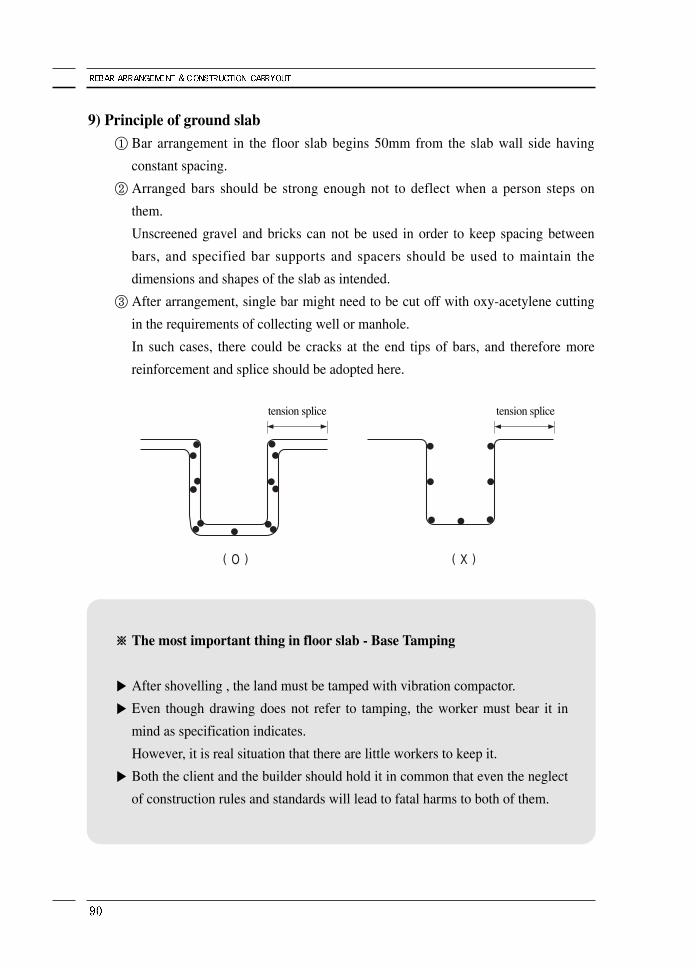
③ After arrangement, single bar might need to be cut off with oxy-acetylene cutting
in the requirements of collecting well or manhole.
In such cases, there could be cracks at the end tips of bars, and therefore more
reinforcement and splice should be adopted here.
※※ The most important thing in floor slab - Base Tamping
▶ After shovelling , the land must be tamped with vibration compactor.
▶ Even though drawing does not refer to tamping, the worker must bear it in
mind as specification indicates.
However, it is real situation that there are little workers to keep it.
▶ Both the client and the builder should hold it in common that even the neglect
of construction rules and standards will lead to fatal harms to both of them.
tension splice tension splice


