
2015 RM BEST Kickoff
Robot Design and Construction Tips
Scott McEwen
September 12, 2015

Overview
Engineering Design Process
Subsystems & System Integration
Communication & Documentation
Design Engineering & Math Examples
Construction Tips
Materials
Fabrication & Safety
Page 2

Engineering Design Process Importance
Proven process for any design/build project
Every team is required to submit a Project Engineering Notebook that documents your process to design, build, and test your robot
Page 3

Engineering Design Process Elements
1. Define the problem
2. Determine the design specifications
3. Develop numerous design alternatives
4. Choose the optimal design
5. Build and test the design
Ref: http://best.eng.auburn.edu/ -> Participants -> File Manager > Public Resources & Training > Team Resources > Engineering Topics
Page 4
1) Define the Problem
EVERYONE read the Rules thoroughly at www.bestinc.org
Participants -> File Manager -> 2015 Game Files
Password: D1g4it
Participants -> Resources
Inventory Consumable & Returnable Kits
Research similar problems and designs Page 5

2) Determine the Design Specs
Clear guidelines for creating viable designs:
Goals
Score lots of low point items, then score high point items
Requirements
Ability to drive through doorways with 1”x4” base
Ability to grab various game pieces
Constraints
Must fit in 24” cube and weigh <= 24 lbs Page 6

3) Develop Numerous Design Alternatives
Engineering design = creative process + content knowledge from variety of disciplines
Brainstorming
Multiple Groups of 3-4? 1+ designs/student?
Sketches, notes, logical & physical models
Scoring Tip: Brainstorming Approaches - How well organized and productive was the brainstorming approach used and documented?
Page 7

4) Choose the Optimal Design
Weigh and document pros & cons of each design
Analysis of gaming strategies and design elements to achieve goals
Do we have the tools and skills to build it?
Scoring Tip: Analytical Evaluation of Design Alternatives - Use of analytical and
mathematical skills in deciding upon and implementing design alternatives
Page 8
5) Build and Test the Design
Invest adequate time and specificity prior to this step
Revisit prior design steps as needed
Scoring Tip: Safety Training *and* safety practices followed & demonstrated
Scoring Tip: Support Documentation
Drawings, photos, test results, etc.
Page 9

Subsystems & System Integration
Drive Platform
Maneuverability about the game field
Speed & position control
Articulated Arm and end effector (grapple)
Rotate left to right
Extend up & down
Extend in & out
Grip efficiently
Programming
Page 10

Communication & Documentation Communication Best Practices
Communication mediums
Traditional
Social media
SCRUM – Daily stand-up meetings
Other
Resolving disagreements/conflicts
What works for your team?
Page 11

Communication & Documentation Engineering Notebook
Document the process used to design, build, and test the robot.
Tell the story of your robot
Documentation is a critical aspect of the Engineering Process. Provides:
Crucial record of the process
Critical info between different groups
Checklist against requirements
Essential information for new people
Page 12
Communication & Documentation Important Dates
Engineering Notebooks are due on Practice Day (Saturday, Oct 17 by 2pm)
Every team MUST submit a Project Engineering Notebook
Notebooks can be hard copy or soft copy
If no notebook on Practice Day, your team will NOT be able to compete on Game Day
Notebooks will be returned on Game Day
Page 13

Design Engineering & Math Examples – Torque
Dimensions and torque
Small Motor http://content.vexrobotics.com/vexpro/pdf/276-1610-Release.PDF
Large Motor http://content.vexrobotics.com/docs/276-1611-Drawing-Rev1A.pdf
Inch-pound = amount of torque required to lift a 1 pound weight that is 1 inch from center of axis of rotation
Computing torque: Torque = Force * Moment Arm
Torque = Weight (pounds) * moment arm (inches)
Total torque = Sum of (weights * moment arms)
Page 14

Design Engineering & Math Examples – Torque
PVC Pipe @ 0.21 lb/ft
Grapple @ 0.5 lb
Waste Cargo Ball @ 0.4 lb
Page 15

Design Engineering & Math Examples – Torque
PVC: (2 ft * 0.21 lb/ft) * 1 ft = 0.42 ft-lb
Grapple: 0.5 lb * 2 ft = 1.00 ft-lb
Ball: 0.4 lb * 2 ft = 0.80 ft-lb
Combined: 0.42 + 1.0 + 0.8 = 2.22 ft-lbs Page 16
Torque = Weight (pounds) * moment arm (feet)
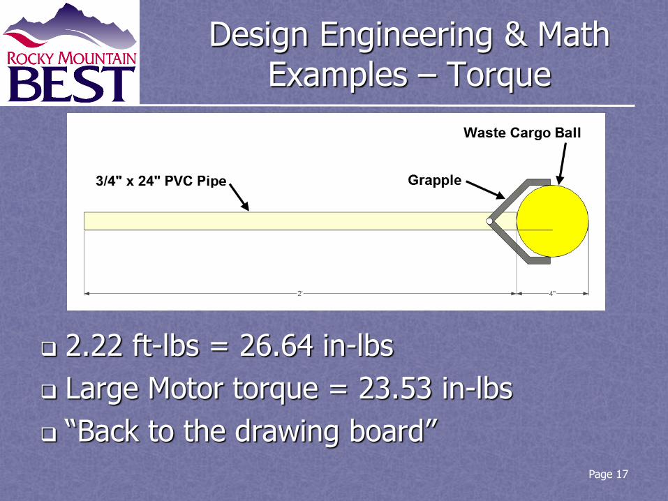
Design Engineering & Math Examples – Torque
2.22 ft-lbs = 26.64 in-lbs
Large Motor torque = 23.53 in-lbs
“Back to the drawing board”
Page 17
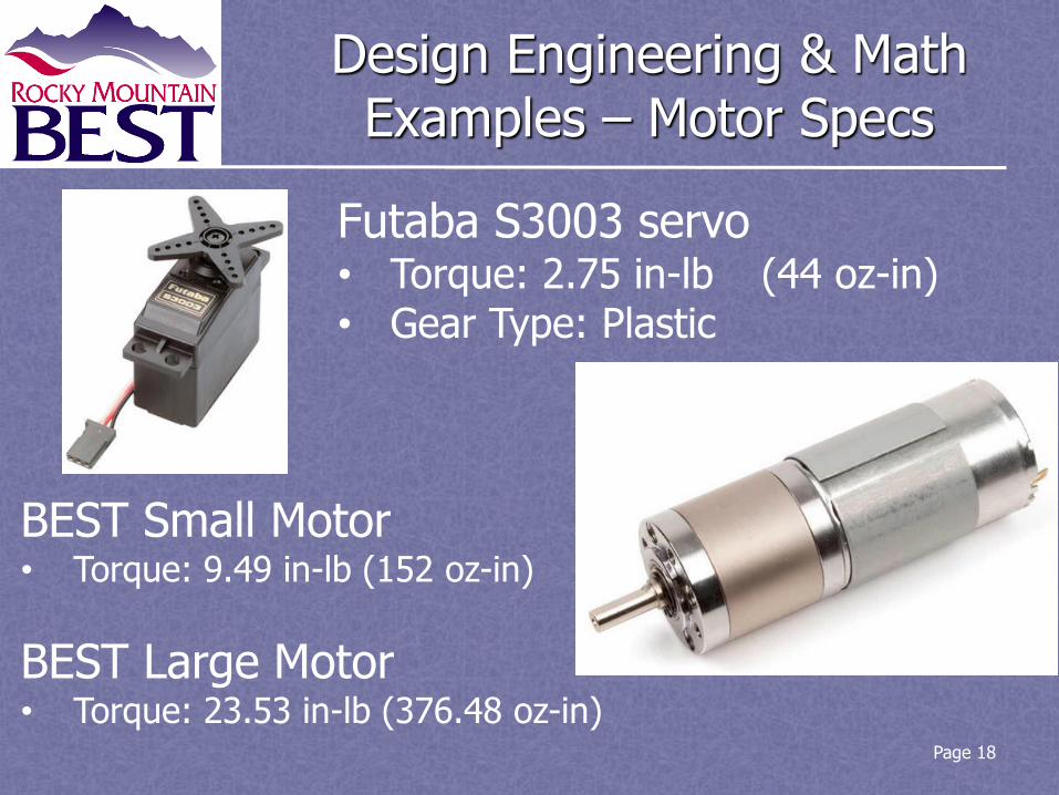
Design Engineering & Math Examples – Motor Specs
Page 18
Futaba S3003 servo • Torque: 2.75 in-lb (44 oz-in) • Gear Type: Plastic
BEST Small Motor • Torque: 9.49 in-lb (152 oz-in)
BEST Large Motor • Torque: 23.53 in-lb (376.48 oz-in)

Design Engineering & Math Examples – Potentiometer (Pot)
Definition. A Pot is an electrical device whose resistance is adjustable. It can be used as an analog sensor to measure angular position of a rotational component, such as a robot arm. The Cortex can use the Pot’s output to control or limit some other component.
Input. Connect Pot’s shaft to a rotational axle or shaft. NOTE: the POT’s total range of motion (i.e., rotation) is 300 degrees.
Output. Connect the Pot’s wiring to a Cortex analog input port.
Operation. As the resistance of the Pot changes, so does the voltage. This varying voltage can be measured by the Cortex and is directly proportional to the angular position of the Pot’s shaft.
Data sheet: http://www.bitechnologies.com/pdfs/p160.pdf
easyC example: https://sites.google.com/site/team3141rx/easyc/arm3
Wiring example: http://www.education.rec.ri.cmu.edu/classes/cal_u/ar/toolbox/content/curriculum/robotics_systems/home_brew/potentiometer/potentiometer.swf
Page 19
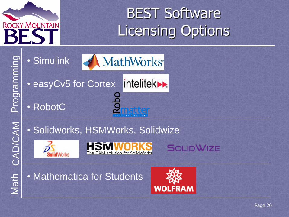
Page 20
• Simulink
• easyCv5 for Cortex
• RobotC
• Solidworks, HSMWorks, Solidwize
• Mathematica for Students
Pro
gra
mm
ing
C
AD
/CA
M
Ma
th
BEST Software Licensing Options
Download Instructions
Software Download Instructions are available on the USB memory stick in the Teacher Packet provided at Kickoff registration.
Change for 2015: RobotC requires web registration to access One Team License
License expires 12/31/15
Page 21

Construction Tips
Materials
Fabrication & Safety
Page 22

Materials
Polypropylene sheet & polycarbonate sheet
Aluminum bar, rod, & sheet
Steel all-thread rod & piano wire
Wood, plywood, 1x4, dowel & ¾” foam board insulation
PVC pipe, tees & elbows (in 3 sizes)
Hardware, Electrical, Tapes & Adhesives
Fasteners & Miscellaneous
Page 23

Fabrication & Safety East High School
Location
1600 City Park Esplanade, Denver
Near Colorado Blvd & Colfax
Woodwork Shop, with CNC router
Contact:
Joel Noble, Shop Teacher
(720) 423-8560
Page 24
Fabrication & Safety Cutting Plastic Sheet (video)
Wear eye protection & secure work
1. Scribe and break – Sturdy knife
Good for 1/8” sheet
2. Jig saw – New blade, 10 teeth/inch
3. Band saw – ½-wide blade, 14 teeth/inch
May cause melting
4. Circular saw – Carbide tip, triple-chip
Plywood blade will cause melting
5. Table saw – 60-80 teeth, triple-chip, 1/8 to ½ inch blade exposed
Page 25
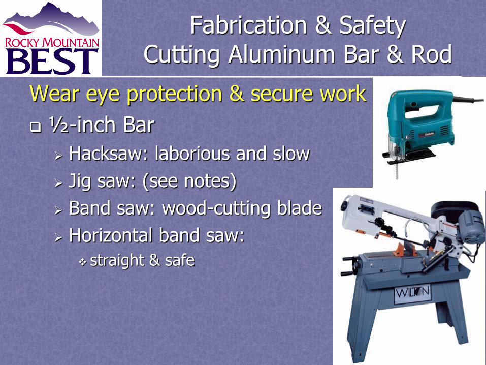
Fabrication & Safety Cutting Aluminum Bar & Rod
Wear eye protection & secure work
½-inch Bar
Hacksaw: laborious and slow
Jig saw: (see notes)
Band saw: wood-cutting blade
Horizontal band saw:
straight & safe
Page 26
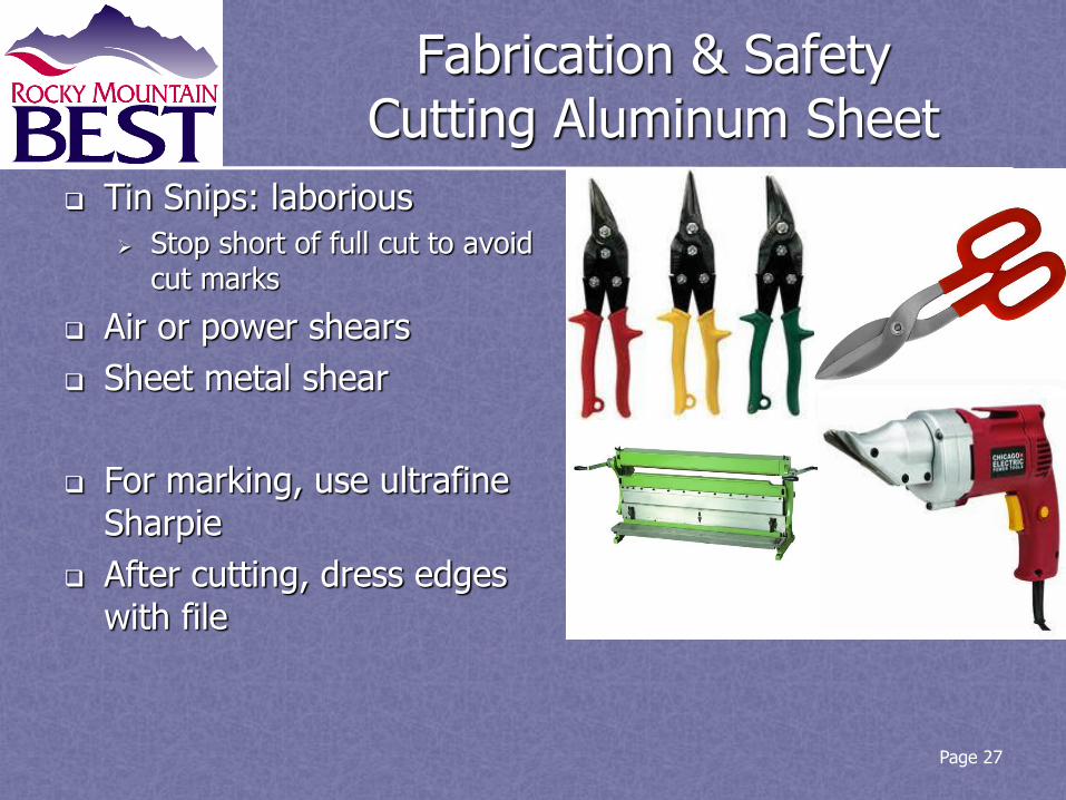
Fabrication & Safety Cutting Aluminum Sheet
Tin Snips: laborious
Stop short of full cut to avoid cut marks
Air or power shears
Sheet metal shear
For marking, use ultrafine Sharpie
After cutting, dress edges with file
Page 27

Fabrication & Safety Bending Aluminum Sheet
Page 28
• Hand bender • Vise • Sheet metal brake
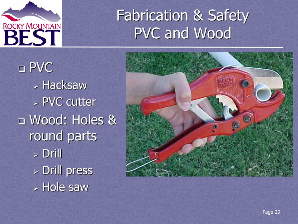
Fabrication & Safety PVC and Wood
PVC
Hacksaw
PVC cutter
Wood: Holes & round parts
Drill
Drill press
Hole saw
Page 29

Page 30

Fabrication & Safety Drill Press Speeds (rpm)
Page 31
Bit Type Plywood & Pine
Acrylic Aluminum Steel
Twist, 1/16” to 3/16” 3000 2500 3000 3000
Twist, 1/4” to 3/8” 3000 2000 2500 1000
Twist, 7/16” to 5/8” 1500 1500 1500 600
Twist, 11/16” to 1” 750 NR 1000 350
Hole Saw, 1” to 2.5” 500 NR 250 NR
Spade bit w/ spurs, 3/8” to 1” 2000 500 NR NR
Circle Cutter, 1.5” to 3” 500 250 NR NR
Circle Cutter, 3.25 to 6” 250 250 NR NR
Circle cutters: Drill 1st side, flip material over, finish on 2nd side
Wear eye protection & secure work
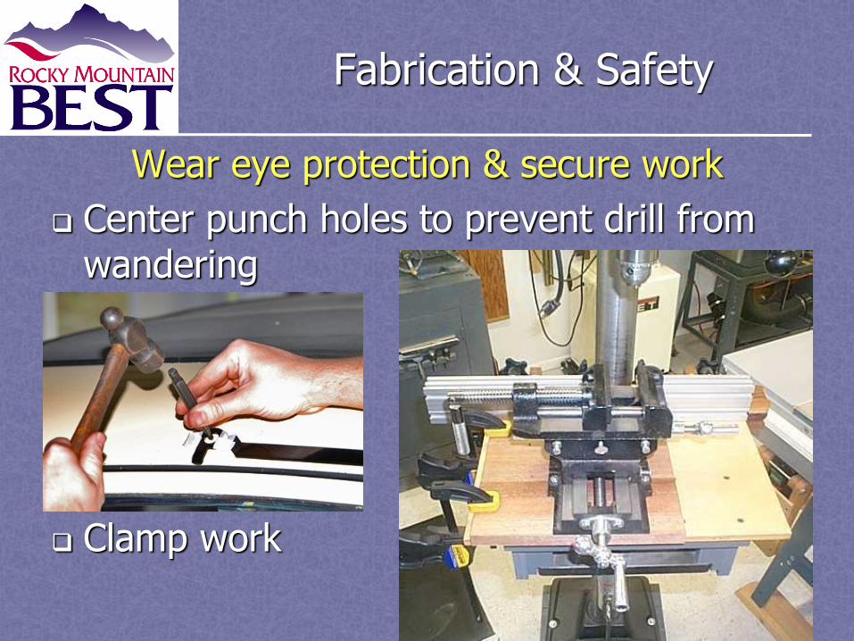
Fabrication & Safety
Wear eye protection & secure work
Center punch holes to prevent drill from wandering
Clamp work
Page 32

Fabrication & Safety Fasteners – Drill and Tap
Page 33
Machine Screw
Drill Bit Number
1/4”-20 8
#10-32 21
#8-32 29
• Threads are cut inside a hole using a tap
• Match hole size (numbered drill bit) to screw
• Screws: size – threads/inch • Purchase drill/tap sets at Ace
Hardware
Fabrication & Safety Foam Board
Cut with Hot knife or sharp utility knife with multiple cuts and minimal pressure against a metal ruler*.
*Read more : http://www.ehow.com/how_4558222_cut-foam-board.html
Draw cut lines before starting
Edges may crumble or shed 34

Fabrication & Safety Electrical Components
Page 35
Proper connection of electrical components Mount Cortex for easy access
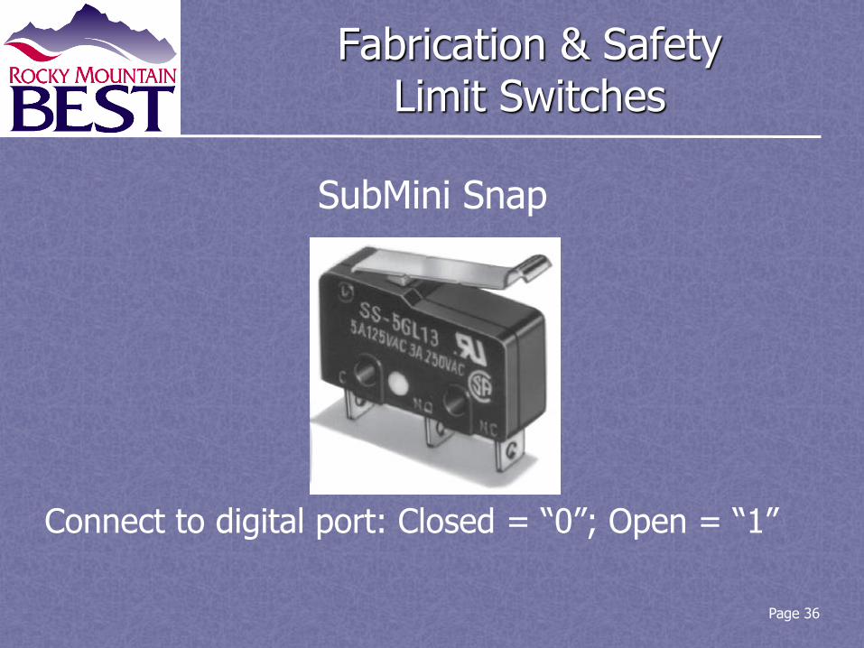
Fabrication & Safety Limit Switches
Page 36
SubMini Snap
Connect to digital port: Closed = “0”; Open = “1”

Fabrication & Safety VEX Motor Mounting Kit
Page 37
• Specifically designed to mount BEST motors
• Flat, but designed to be easily bent

Fabrication & Safety BEST References
http://best.eng.auburn.edu/b_game_rules.php
http://best.eng.auburn.edu/stored_procedures/folder-manager/
1. 2015 RMBEST Consumable Kit List
2. 2015 RMBEST Returnable Kit List
3. BEST Large Motor Spec Sheet
4. BEST Small Motor Spec Sheet
5. BEST Generic Kit Usage Guide
6. 4.X VEXnet Firmware Upgrade Utility Operating Instructions and Installation
7. Cortex Microcontroller and VEXnet Joystick User Guide
8. VEX Cortex Pin-out
9. Introduction to easyC & Cortex (Intelitek)
10. Google for PDF: “Tools, Tips and Materials” by David Kwast Page 38


