Download - ACVATIXTM Radiator valves VDN1.. VEN1
CE1N2105en2020-10-19
Smart Infrastructure
2105
EN 215
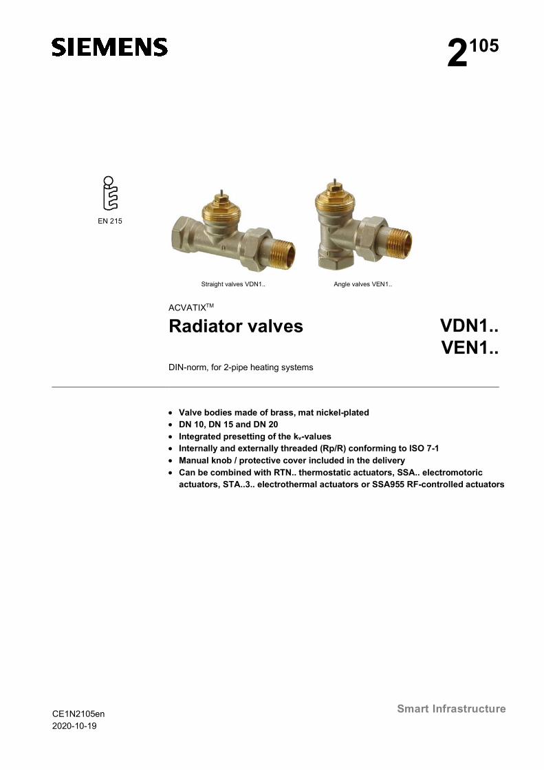
Straight valves VDN1.. Angle valves VEN1..
ACVATIXTM
Radiator valves VDN1..VEN1..
DIN-norm, for 2-pipe heating systems
· Valve bodies made of brass, mat nickel-plated· DN 10, DN 15 and DN 20· Integrated presetting of the kv-values· Internally and externally threaded (Rp/R) conforming to ISO 7-1· Manual knob / protective cover included in the delivery· Can be combined with RTN.. thermostatic actuators, SSA.. electromotoric
actuators, STA..3.. electrothermal actuators or SSA955 RF-controlled actuators
2/14
Siemens Radiator valves CE1N2105enSmart Infrastructure 2020-10-19
Use
The radiator valves are used in hot water heating plants for individual room or zonetemperature control and limitation. They are basically recommended in all rooms,especially where heat gains or different temperature levels occur.
Type summary
Productnumberstraight
Productnumberangle
DN XP kv-value [m3/h]1 - N
kvs-value [m3/h]without actuator
N
VDN110 VEN110 10
XP = 2 0.072…0.43
0.63XP = 1.5 0.057…0.33
XP = 1 0.037…0.22
VDN115 VEN115 15
XP = 2 0.073…0.50
0.89XP = 1.5 0.058…0.40
XP = 1 0.038…0.27
VDN120 VEN120 20
XP = 2 0.22…0.70
1.41XP = 1.5 0.17…0.55
XP = 1 0.11…0.36
Ordering
Valves and accessories are packed separately.
Equipment combinations
Actuators Product numbers Data sheetThermostatic actuators RTN.. N2111
Electromotoric actuators SSA131 / SSA331 / SSA161.05 A6V11858276SSA151.05HF / SSA161.05HF A6V11858278
RF-controlled electromotoric actuators SSA955 N2700
Electrothermal actuators STA..3.. N4884
Example: Product number Order number Description Quantity
VDN120 VDN120 straight valves 2
ATN2 ATN2 protection against dismantling 1
Delivery
3/14
Siemens Radiator valves CE1N2105enSmart Infrastructure 2020-10-19
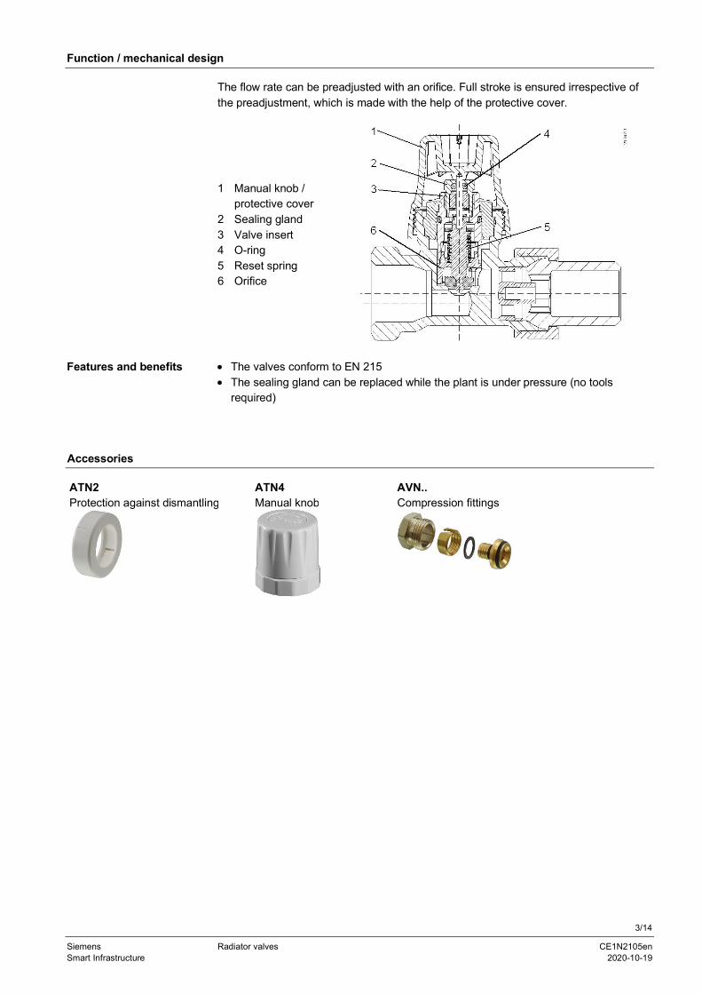
Function / mechanical design
The flow rate can be preadjusted with an orifice. Full stroke is ensured irrespective ofthe preadjustment, which is made with the help of the protective cover.
1 Manual knob /protective cover
2 Sealing gland3 Valve insert4 O-ring5 Reset spring6 Orifice
· The valves conform to EN 215· The sealing gland can be replaced while the plant is under pressure (no tools
required)
Accessories
ATN2Protection against dismantling
ATN4Manual knob
AVN..Compression fittings
Features and benefits

4/14
Siemens Radiator valves CE1N2105enSmart Infrastructure 2020-10-19
Engineering notes
The reference numbers for preadjustment are given in the table with the kv-values (seepage 5) and in the valve sizing charts (see pages 7 – 6).
1. Calculate the volumetric water flow 100V&
1
100100
f1.163.
´D´=
TQV [m3/h]
Q100 = heat demand [kW]ΔT = temperature differential [K]1.163 = constant of waterf1 = correction factor = 1 for water
2. Define the pressure drop Δpv100 across the fully open valve
In most types of plant, a differential pressure Δpv100 of 0.05 to 0.2 bar is adequate.
3. Calculation of the nominal flow value kv
100
100
vv Δp
Vk&
= [m3/h] Δpv100 = differential pressure across thevalve [bar]
Heat demand Q100 = 1.2 kW
Temperature differential ΔT = 20 K
Water volume
201.1631.2.
100´
=V= 0.052 m3/h
= 52 l/h
Required differential pressure across the valve Δpv100 = 0.1 bar
Flow0.1
0.052=vk = 0.17 m3/h
SolutionAccording to the chart (refer to "Valve sizing charts", page 7 or table with kv-values), thepreadjustment required by a VDN110 3/8“ valve is 2.
Tips· Noiseless operation is ensured by a pump that provides no more pressure than is
needed to transport the required amount of water.· To keep the valve free from dirt particles, it is recommended to install a strainer.
Example:

5/14
Siemens Radiator valves CE1N2105enSmart Infrastructure 2020-10-19
The kv value gives the volumetric water flow 100V.
in m3/h at a pressure drop Δpv100
across the valve of 1 bar.
Control range with actuatorsSSA.. and STA..3.. ü ü ü ü ü ü ü
Control range of thermostaticactuators RTN.. ü ü ü ü ü ü
Reference numbers for pre-adjustment 1 2 3 4 5 N N(kvs)
VDN110 / VEN110XP 2K 0.072 0.17 0.24 0.28 0.37 0.43
0.63VDN110 / VEN110XP 1.5K 0.057 0.135 0.19 0.23 0.29 0.33
VDN110 / VEN110XP 1K 0.037 0.089 0.13 0.145 0.19 0.22
VDN115 / VEN115XP 2K 0.07 0.17 0.28 0.36 0.45 0.50
0.89VDN115 / VEN115XP 1.5K 0.058 0.14 0.23 0.28 0.35 0.4
VDN115 / VEN115XP 1K 0.038 0.9 0.15 0.18 0.24 0.27
VDN120 / VEN120XP 2K 0.22 0.35 0.44 0.52 0.60 0.71
1.41VDN120 / VEN120XP 1.5K 0.17 0.27 0.35 0.42 0.46 0.55
VDN120 / VEN120XP 1K 0.11 0.18 0.23 0.28 0.31 0.36
kv-values
kv-values [m3/h] at thedifferent preadjustedpositions
6/14
Siemens Radiator valves CE1N2105enSmart Infrastructure 2020-10-19
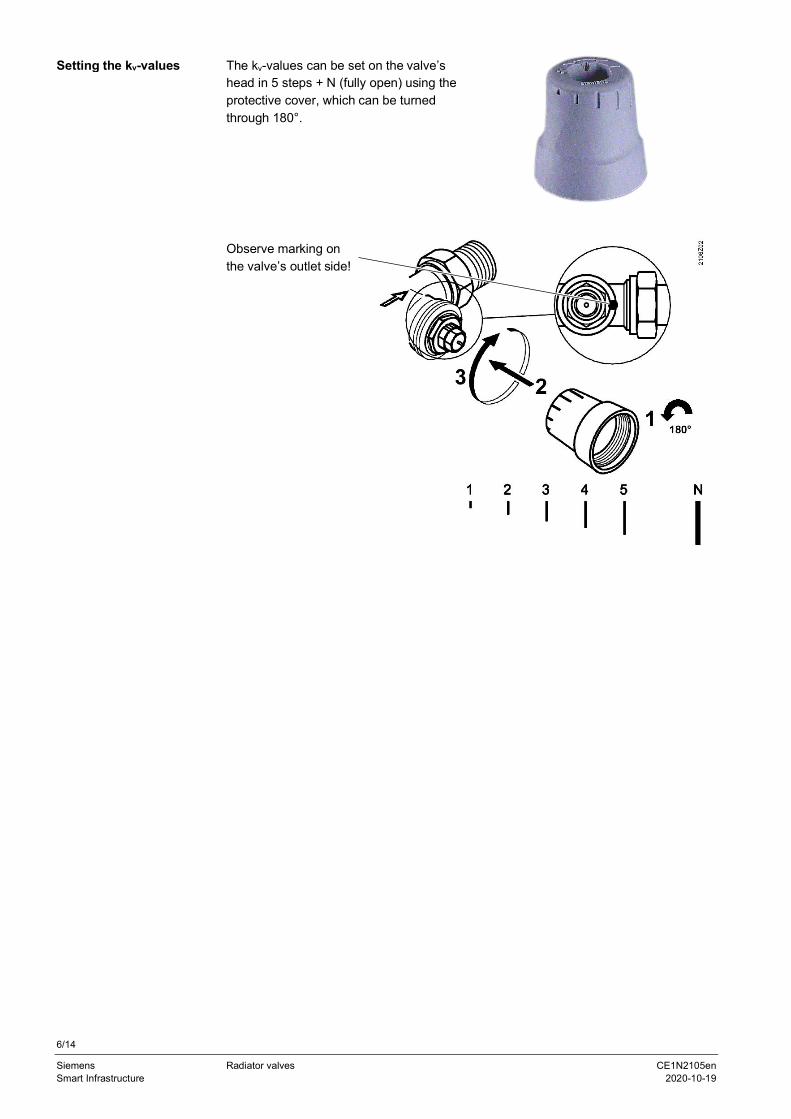
The kv-values can be set on the valve’shead in 5 steps + N (fully open) using theprotective cover, which can be turnedthrough 180°.
Observe marking onthe valve’s outlet side!
Setting the kv-values

7/14
Siemens Radiator valves CE1N2105enSmart Infrastructure 2020-10-19
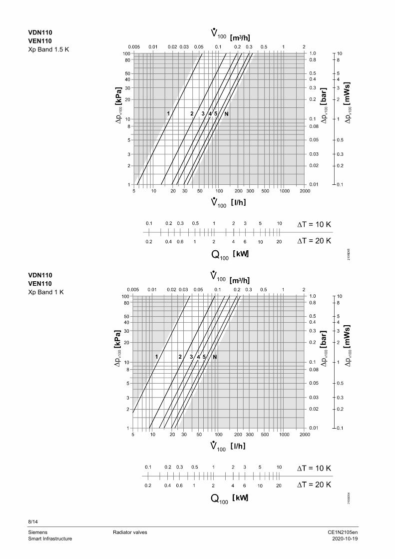
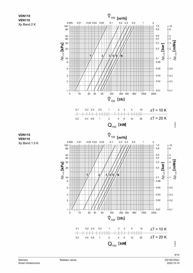
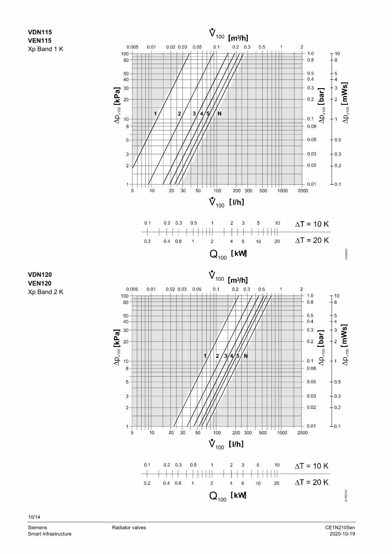
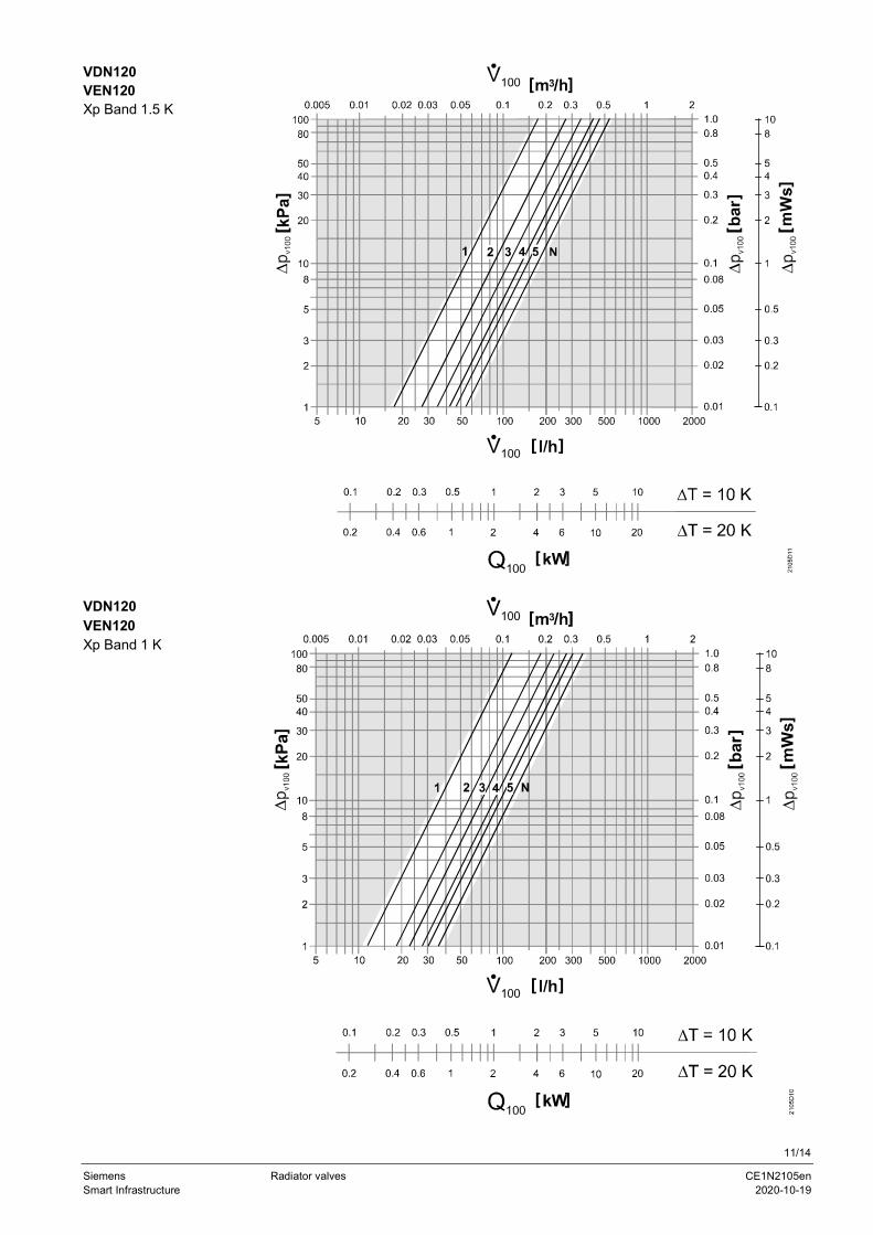
Valve sizing charts
VDN110VEN110Xp Band 2 K
8/14
Siemens Radiator valves CE1N2105enSmart Infrastructure 2020-10-19
VDN110VEN110Xp Band 1.5 K
VDN110VEN110Xp Band 1 K
9/14
Siemens Radiator valves CE1N2105enSmart Infrastructure 2020-10-19
VDN115VEN115Xp Band 2 K
VDN115VEN115Xp Band 1.5 K
10/14
Siemens Radiator valves CE1N2105enSmart Infrastructure 2020-10-19
VDN115VEN115Xp Band 1 K
VDN120VEN120Xp Band 2 K
11/14
Siemens Radiator valves CE1N2105enSmart Infrastructure 2020-10-19
VDN120VEN120Xp Band 1.5 K
VDN120VEN120Xp Band 1 K
12/14
Siemens Radiator valves CE1N2105enSmart Infrastructure 2020-10-19
Notes
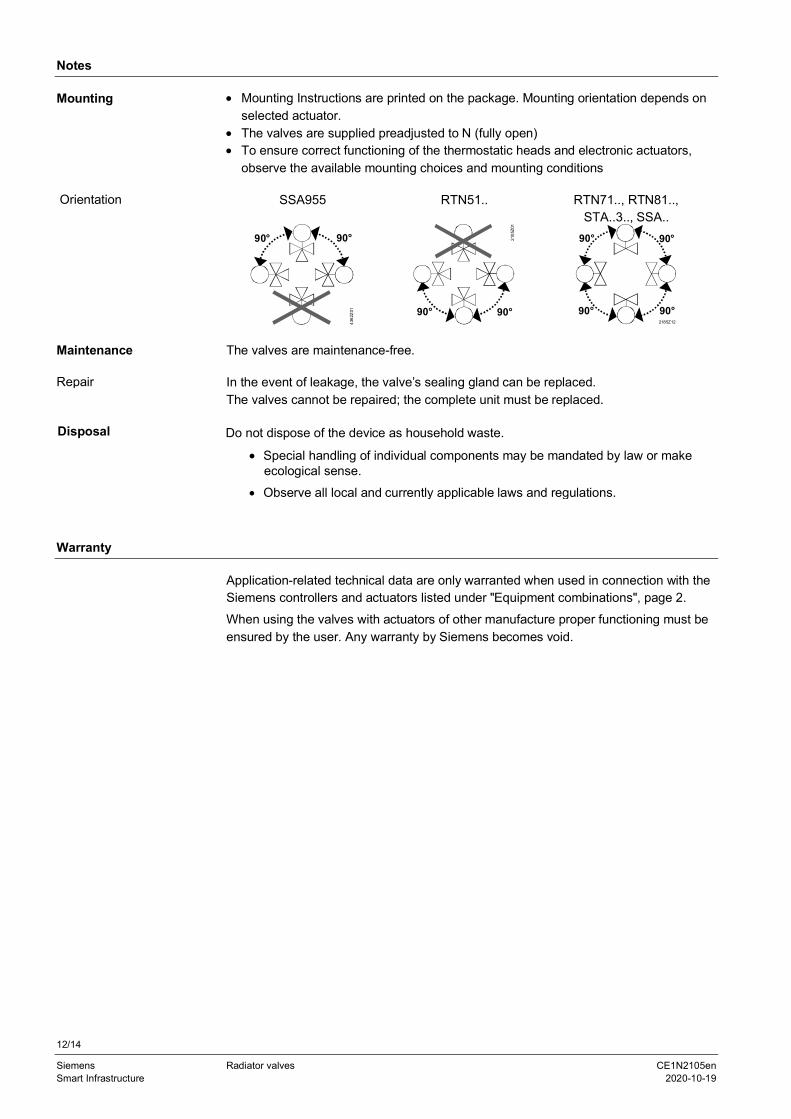
· Mounting Instructions are printed on the package. Mounting orientation depends onselected actuator.
· The valves are supplied preadjusted to N (fully open)· To ensure correct functioning of the thermostatic heads and electronic actuators,
observe the available mounting choices and mounting conditions
SSA955 RTN51.. RTN71.., RTN81..,STA..3.., SSA..
90°
4362
Z01
90°
90°
2105
Z01
90° 90°2185Z12
90°
90° 90°
The valves are maintenance-free.
In the event of leakage, the valve’s sealing gland can be replaced.The valves cannot be repaired; the complete unit must be replaced.
Disposal Do not dispose of the device as household waste.
· Special handling of individual components may be mandated by law or makeecological sense.
· Observe all local and currently applicable laws and regulations.
Warranty
Application-related technical data are only warranted when used in connection with theSiemens controllers and actuators listed under "Equipment combinations", page 2.When using the valves with actuators of other manufacture proper functioning must beensured by the user. Any warranty by Siemens becomes void.
Mounting
Orientation
Maintenance
Repair
13/14
Siemens Radiator valves CE1N2105enSmart Infrastructure 2020-10-19
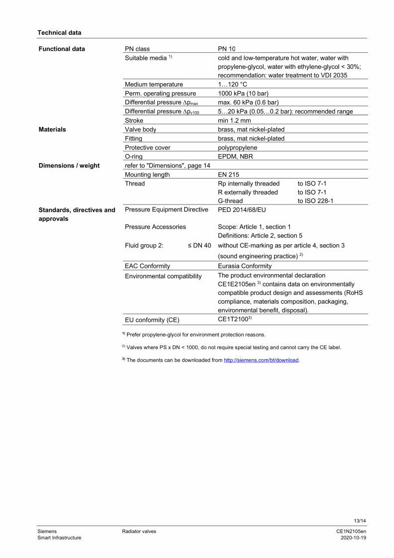
Technical data
Functional data PN class PN 10Suitable media 1) cold and low-temperature hot water, water with
propylene-glycol, water with ethylene-glycol < 30%;recommendation: water treatment to VDI 2035
Medium temperature 1…120 °CPerm. operating pressure 1000 kPa (10 bar)Differential pressure Dpmax max. 60 kPa (0.6 bar)Differential pressure Dpv100 5…20 kPa (0.05…0.2 bar): recommended rangeStroke min 1.2 mm
Materials Valve body brass, mat nickel-platedFitting brass, mat nickel-platedProtective cover polypropyleneO-ring EPDM, NBR
Dimensions / weight refer to "Dimensions", page 14Mounting length EN 215Thread Rp internally threaded
R externally threadedG-thread
to ISO 7-1to ISO 7-1to ISO 228-1
Standards, directives andapprovals
Pressure Equipment Directive PED 2014/68/EU
Pressure Accessories Scope: Article 1, section 1Definitions: Article 2, section 5
Fluid group 2: ≤ DN 40 without CE-marking as per article 4, section 3(sound engineering practice) 2)
EAC Conformity Eurasia ConformityEnvironmental compatibility The product environmental declaration
CE1E2105en 3) contains data on environmentallycompatible product design and assessments (RoHScompliance, materials composition, packaging,environmental benefit, disposal).
EU conformity (CE) CE1T21003)
1) Prefer propylene-glycol for environment protection reasons.
2) Valves where PS x DN < 1000, do not require special testing and cannot carry the CE label.
3) The documents can be downloaded from http://siemens.com/bt/download.
14/14
Siemens Radiator valves CE1N2105enSmart Infrastructure 2020-10-19
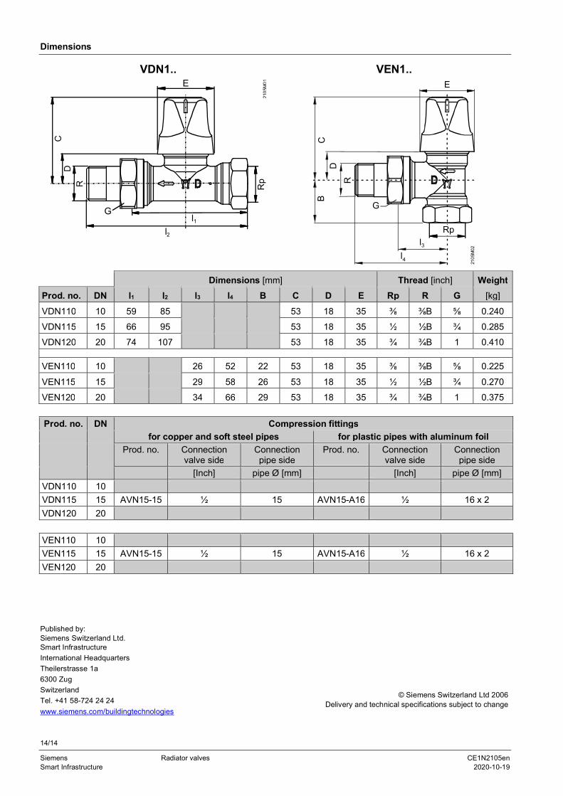
Dimensions
VDN1.. VEN1..
2105
M01
G
Rp
l2l1
CD
ER
G
2105
M02
l3
E
Rp
DC
B
R
l4
Dimensions [mm] Thread [inch] WeightProd. no. DN l1 l2 l3 l4 B C D E Rp R G [kg]
VDN110 10 59 85 53 18 35 ⅜ ⅜B ⅝ 0.240VDN115 15 66 95 53 18 35 ½ ½B ¾ 0.285VDN120 20 74 107 53 18 35 ¾ ¾B 1 0.410
VEN110 10 26 52 22 53 18 35 ⅜ ⅜B ⅝ 0.225
VEN115 15 29 58 26 53 18 35 ½ ½B ¾ 0.270VEN120 20 34 66 29 53 18 35 ¾ ¾B 1 0.375
Prod. no. DN Compression fittingsfor copper and soft steel pipes for plastic pipes with aluminum foil
Prod. no. Connectionvalve side
Connectionpipe side
Prod. no. Connectionvalve side
Connectionpipe side
[Inch] pipe Ø [mm] [Inch] pipe Ø [mm]VDN110 10VDN115 15 AVN15-15 ½ 15 AVN15-A16 ½ 16 x 2VDN120 20
VEN110 10VEN115 15 AVN15-15 ½ 15 AVN15-A16 ½ 16 x 2VEN120 20
Published by:Siemens Switzerland Ltd.Smart InfrastructureInternational HeadquartersTheilerstrasse 1a6300 ZugSwitzerlandTel. +41 58-724 24 24www.siemens.com/buildingtechnologies
© Siemens Switzerland Ltd 2006Delivery and technical specifications subject to change


