
Instructions
Installation
Commissioning
Operation
Maintenance
FLUOKIT M24+
AREVA T&D
AIR INSULATED SWITCHGEAR


Table of contents
i
1 AREVA at your service 1 . . . . . . . . . . . . . . . . . . . . . . . . . . . . . . . . . . . . . . . . . . . . . . . . . .
1.1 Our Service Unit: our specialists, and suitably adapted services... 1 . . . . . . . . . . . . . . . . . . . . . . . . . . . .
1.2 AREVA T&D Training Centre: your training partner 1 . . . . . . . . . . . . . . . . . . . . . . . . . . . . . . . . . . . . . . . . .
2 With regards to this User Manual 2 . . . . . . . . . . . . . . . . . . . . . . . . . . . . . . . . . . . . . . . .
2.1 Eco−design concept and revalorisation of the materials used 2 . . . . . . . . . . . . . . . . . . . . . . . . . . . . . . . . .
2.2 Responsibilities 2 . . . . . . . . . . . . . . . . . . . . . . . . . . . . . . . . . . . . . . . . . . . . . . . . . . . . . . . . . . . . . . . . . . . . . . . .
2.3 Reminder concerning normal service conditions (in accordance with IEC 60694) 2 . . . . . . . . . . . . . . .
* Permissible ambient temperature 2 . . . . . . . . . . . . . . . . . . . . . . . . . . . . . . . . . . . . . . . . . . . . . . . . . . . . . . .
* Installation altitude 2 . . . . . . . . . . . . . . . . . . . . . . . . . . . . . . . . . . . . . . . . . . . . . . . . . . . . . . . . . . . . . . . . . . . .
* Atmospheric pollution 2 . . . . . . . . . . . . . . . . . . . . . . . . . . . . . . . . . . . . . . . . . . . . . . . . . . . . . . . . . . . . . . . . .
* Permissible atmospheric humidity level 2 . . . . . . . . . . . . . . . . . . . . . . . . . . . . . . . . . . . . . . . . . . . . . . . . . .
2.4 Particular instructions for operations and interventions on energized equipment 3 . . . . . . . . . . . . . . . .
2.5 Other technical notices to be consulted 3 . . . . . . . . . . . . . . . . . . . . . . . . . . . . . . . . . . . . . . . . . . . . . . . . . . .
2.6 Tools and products (not supplied) required for the operations described in this notice 3 . . . . . . . . . . . .
2.7 Symbols & conventions 4 . . . . . . . . . . . . . . . . . . . . . . . . . . . . . . . . . . . . . . . . . . . . . . . . . . . . . . . . . . . . . . . . .
2.8 Tightening torque values for standard assemblies (nut + bolt) 4 . . . . . . . . . . . . . . . . . . . . . . . . . . . . . . . .
3 Presentation 5 . . . . . . . . . . . . . . . . . . . . . . . . . . . . . . . . . . . . . . . . . . . . . . . . . . . . . . . . . . .
3.1 Description 5 . . . . . . . . . . . . . . . . . . . . . . . . . . . . . . . . . . . . . . . . . . . . . . . . . . . . . . . . . . . . . . . . . . . . . . . . . . .
3.2 Dimensions and approximate weight of the Functional Units 5 . . . . . . . . . . . . . . . . . . . . . . . . . . . . . . . . .
3.3 Presentation of the Functional Units 6 . . . . . . . . . . . . . . . . . . . . . . . . . . . . . . . . . . . . . . . . . . . . . . . . . . . . . .
4 Packaging − Handling − Storage 10 . . . . . . . . . . . . . . . . . . . . . . . . . . . . . . . . . . . . . . . . .
4.1 Transport − Delivery 10 . . . . . . . . . . . . . . . . . . . . . . . . . . . . . . . . . . . . . . . . . . . . . . . . . . . . . . . . . . . . . . . . . . . .
4.2 Packaging for the Functional Units 10 . . . . . . . . . . . . . . . . . . . . . . . . . . . . . . . . . . . . . . . . . . . . . . . . . . . . . . .
4.3 The accessories package 10 . . . . . . . . . . . . . . . . . . . . . . . . . . . . . . . . . . . . . . . . . . . . . . . . . . . . . . . . . . . . . . .
4.4 Reception/Acceptance 10 . . . . . . . . . . . . . . . . . . . . . . . . . . . . . . . . . . . . . . . . . . . . . . . . . . . . . . . . . . . . . . . . . .
4.5 Location of the technical data plates 11 . . . . . . . . . . . . . . . . . . . . . . . . . . . . . . . . . . . . . . . . . . . . . . . . . . . . . .
4.6 Handling 11 . . . . . . . . . . . . . . . . . . . . . . . . . . . . . . . . . . . . . . . . . . . . . . . . . . . . . . . . . . . . . . . . . . . . . . . . . . . . . .
4.7 Storage conditions 12 . . . . . . . . . . . . . . . . . . . . . . . . . . . . . . . . . . . . . . . . . . . . . . . . . . . . . . . . . . . . . . . . . . . . .
4.8 Intervention levels 12 . . . . . . . . . . . . . . . . . . . . . . . . . . . . . . . . . . . . . . . . . . . . . . . . . . . . . . . . . . . . . . . . . . . . .
4.9 Specific recommendations for storage durations of less than 6 months 12 . . . . . . . . . . . . . . . . . . . . . . . .
4.10 Specific recommendations for storage durations of between 6 and 12 months 12 . . . . . . . . . . . . . . . . . .
4.11 Specific recommendations for storage durations of between 12 and 24 months 12 . . . . . . . . . . . . . . . . .
5 Unpacking and installing the equipment 13 . . . . . . . . . . . . . . . . . . . . . . . . . . . . . . . . .
5.1 Type of Civil Engineering 13 . . . . . . . . . . . . . . . . . . . . . . . . . . . . . . . . . . . . . . . . . . . . . . . . . . . . . . . . . . . . . . .
5.2 Unpacking the Functional Units 13 . . . . . . . . . . . . . . . . . . . . . . . . . . . . . . . . . . . . . . . . . . . . . . . . . . . . . . . . . .
5.3 Handling the Functional Unit 13 . . . . . . . . . . . . . . . . . . . . . . . . . . . . . . . . . . . . . . . . . . . . . . . . . . . . . . . . . . . .
5.4 Installation of a switchboard 14 . . . . . . . . . . . . . . . . . . . . . . . . . . . . . . . . . . . . . . . . . . . . . . . . . . . . . . . . . . . . .
5.5 Installing Functional Units 14 . . . . . . . . . . . . . . . . . . . . . . . . . . . . . . . . . . . . . . . . . . . . . . . . . . . . . . . . . . . . . . .
5.6 Revalorizing packaging waste 14 . . . . . . . . . . . . . . . . . . . . . . . . . . . . . . . . . . . . . . . . . . . . . . . . . . . . . . . . . . .
ii
6 Installation 15 . . . . . . . . . . . . . . . . . . . . . . . . . . . . . . . . . . . . . . . . . . . . . . . . . . . . . . . . . . . . .
6.1 Installation of each Functional Unit 15 . . . . . . . . . . . . . . . . . . . . . . . . . . . . . . . . . . . . . . . . . . . . . . . . . . . . . . .
6.2 Functional units with internal arc withstand protection 15 . . . . . . . . . . . . . . . . . . . . . . . . . . . . . . . . . . . . . . .
6.3 Fixing the Functional Units to the floor 16 . . . . . . . . . . . . . . . . . . . . . . . . . . . . . . . . . . . . . . . . . . . . . . . . . . . .
6.4 Connection of the inter−Functional Units grounding circuit 16 . . . . . . . . . . . . . . . . . . . . . . . . . . . . . . . . . . .
6.5 General switchboard earthing connection to the earthing spike of the building 16 . . . . . . . . . . . . . . . . . .
6.6 Standard busbar connections 17 . . . . . . . . . . . . . . . . . . . . . . . . . . . . . . . . . . . . . . . . . . . . . . . . . . . . . . . . . . . .
6.7 Connection of a 1250 A busbar 18 . . . . . . . . . . . . . . . . . . . . . . . . . . . . . . . . . . . . . . . . . . . . . . . . . . . . . . . . . .
6.8 Connection between 630 A and 1250 A busbars 18 . . . . . . . . . . . . . . . . . . . . . . . . . . . . . . . . . . . . . . . . . . .
6.9 Connecting a 1,250 A busbar to a 1,250 A isolating switch (PBB or PGC) 19 . . . . . . . . . . . . . . . . . . . . .
6.10 Coupling of a Fluokit M24+ functional unit to a Fluokit M24 functional unit 20 . . . . . . . . . . . . . . . . . . . . .
7 Connection of the HV cables 21 . . . . . . . . . . . . . . . . . . . . . . . . . . . . . . . . . . . . . . . . . . . .
7.1 Preparation of the HV cable connections 21 . . . . . . . . . . . . . . . . . . . . . . . . . . . . . . . . . . . . . . . . . . . . . . . . . .
7.2 Connection instructions 22 . . . . . . . . . . . . . . . . . . . . . . . . . . . . . . . . . . . . . . . . . . . . . . . . . . . . . . . . . . . . . . . . .
7.3 Preparation of the cables 22 . . . . . . . . . . . . . . . . . . . . . . . . . . . . . . . . . . . . . . . . . . . . . . . . . . . . . . . . . . . . . . .
7.4 Connection of an IS Functional Unit 23 . . . . . . . . . . . . . . . . . . . . . . . . . . . . . . . . . . . . . . . . . . . . . . . . . . . . . .
7.5 Connection of a PF or PFA Functional Unit 23 . . . . . . . . . . . . . . . . . . . . . . . . . . . . . . . . . . . . . . . . . . . . . . . .
7.6 Clamping the cables and connection of the screen braids 24 . . . . . . . . . . . . . . . . . . . . . . . . . . . . . . . . . . .
7.7 Connection in a PGC or IS Functional Unit equipped with current transformers 24 . . . . . . . . . . . . . . . . .
7.8 Earthing the screen braids 24 . . . . . . . . . . . . . . . . . . . . . . . . . . . . . . . . . . . . . . . . . . . . . . . . . . . . . . . . . . . . . .
7.9 Fitting the fuses on to the PF−PFA Functional Units 25 . . . . . . . . . . . . . . . . . . . . . . . . . . . . . . . . . . . . . . . . .
7.10 The sensors (rings) for fault detection and signalling 26 . . . . . . . . . . . . . . . . . . . . . . . . . . . . . . . . . . . . . . . .
7.11 Mounting the rings 26 . . . . . . . . . . . . . . . . . . . . . . . . . . . . . . . . . . . . . . . . . . . . . . . . . . . . . . . . . . . . . . . . . . . . .
7.12 Special instructions at the end of the connections 26 . . . . . . . . . . . . . . . . . . . . . . . . . . . . . . . . . . . . . . . . . .
8 Connection of the low voltage circuits 27 . . . . . . . . . . . . . . . . . . . . . . . . . . . . . . . . . . .
8.1 Marking the functional unit on the LV box cover 27 . . . . . . . . . . . . . . . . . . . . . . . . . . . . . . . . . . . . . . . . . . . .
8.2 Motorised remote control interface for the switches [option] 27 . . . . . . . . . . . . . . . . . . . . . . . . . . . . . . . . . .
8.3 Connection of the "Metering" low voltage wiring to the PGB Functional Unit 28 . . . . . . . . . . . . . . . . . . . .
8.4 Connection of the "Metering" low voltage wiring to the TM Functional Unit 28 . . . . . . . . . . . . . . . . . . . . .
9 Double shunt layout function 29 . . . . . . . . . . . . . . . . . . . . . . . . . . . . . . . . . . . . . . . . . . .
9.1 Foolproofing of the remote control connector [Public Distribution] 29 . . . . . . . . . . . . . . . . . . . . . . . . . . . . .
9.2 Identification and function of the pins [Public Distribution] 30 . . . . . . . . . . . . . . . . . . . . . . . . . . . . . . . . . . . .
9.3 Mounting and connection of the rings 30 . . . . . . . . . . . . . . . . . . . . . . . . . . . . . . . . . . . . . . . . . . . . . . . . . . . . .
9.4 Commissioning the double shunt layout 30 . . . . . . . . . . . . . . . . . . . . . . . . . . . . . . . . . . . . . . . . . . . . . . . . . . .
10 Normal/Backup function 31 . . . . . . . . . . . . . . . . . . . . . . . . . . . . . . . . . . . . . . . . . . . . . . . .
10.1 Principle 31 . . . . . . . . . . . . . . . . . . . . . . . . . . . . . . . . . . . . . . . . . . . . . . . . . . . . . . . . . . . . . . . . . . . . . . . . . . . . . .
10.2 Presentation 31 . . . . . . . . . . . . . . . . . . . . . . . . . . . . . . . . . . . . . . . . . . . . . . . . . . . . . . . . . . . . . . . . . . . . . . . . . .
10.3 Mechanical interlocking forbidding connection in parallel 32 . . . . . . . . . . . . . . . . . . . . . . . . . . . . . . . . . . . .

Table of contents
iii
11 Operating accessories and instructions 33 . . . . . . . . . . . . . . . . . . . . . . . . . . . . . . . . .
11.1 Reminder 33 . . . . . . . . . . . . . . . . . . . . . . . . . . . . . . . . . . . . . . . . . . . . . . . . . . . . . . . . . . . . . . . . . . . . . . . . . . . . .
11.2 Wall storage rack (optional) 33 . . . . . . . . . . . . . . . . . . . . . . . . . . . . . . . . . . . . . . . . . . . . . . . . . . . . . . . . . . . . .
11.3 Operation of a Functional Unit equipped with a C410−C410S−C410M control 33 . . . . . . . . . . . . . . . . . . .
11.4 Operation of a Functional Unit equipped with a C430−C430M control 33 . . . . . . . . . . . . . . . . . . . . . . . . . .
11.5 Operation of a Functional Unit equipped with a C440−C440M control 34 . . . . . . . . . . . . . . . . . . . . . . . . . .
11.6 Cable testing 34 . . . . . . . . . . . . . . . . . . . . . . . . . . . . . . . . . . . . . . . . . . . . . . . . . . . . . . . . . . . . . . . . . . . . . . . . . .
11.7 Installing the removable earthing switch device 34 . . . . . . . . . . . . . . . . . . . . . . . . . . . . . . . . . . . . . . . . . . . .
12 Operating the TM Functional Unit 35 . . . . . . . . . . . . . . . . . . . . . . . . . . . . . . . . . . . . . . .
12.1 Operating manoeuvres for the TM Functional Unit 35 . . . . . . . . . . . . . . . . . . . . . . . . . . . . . . . . . . . . . . . . . .
13 Operating the PGB Functional Unit 36 . . . . . . . . . . . . . . . . . . . . . . . . . . . . . . . . . . . . . .
13.1 Opening the upstream and downstream earthing switches 36 . . . . . . . . . . . . . . . . . . . . . . . . . . . . . . . . . . .
13.2 Closing the load break switch 36 . . . . . . . . . . . . . . . . . . . . . . . . . . . . . . . . . . . . . . . . . . . . . . . . . . . . . . . . . . . .
13.3 Closing the circuit breaker 37 . . . . . . . . . . . . . . . . . . . . . . . . . . . . . . . . . . . . . . . . . . . . . . . . . . . . . . . . . . . . . .
13.4 De−energizing a PGB Functional Unit 37 . . . . . . . . . . . . . . . . . . . . . . . . . . . . . . . . . . . . . . . . . . . . . . . . . . . . .
14 Operating the PGC Functional Unit 38 . . . . . . . . . . . . . . . . . . . . . . . . . . . . . . . . . . . . . .
14.1 Opening the downstream earthing switch. 38 . . . . . . . . . . . . . . . . . . . . . . . . . . . . . . . . . . . . . . . . . . . . . . . . .
14.2 Opening the upstream earthing switch. 38 . . . . . . . . . . . . . . . . . . . . . . . . . . . . . . . . . . . . . . . . . . . . . . . . . . .
14.3 Closing the load break switch 39 . . . . . . . . . . . . . . . . . . . . . . . . . . . . . . . . . . . . . . . . . . . . . . . . . . . . . . . . . . . .
14.4 Closing the circuit breaker 39 . . . . . . . . . . . . . . . . . . . . . . . . . . . . . . . . . . . . . . . . . . . . . . . . . . . . . . . . . . . . . .
14.5 De−energizing a PGC Functional Unit 39 . . . . . . . . . . . . . . . . . . . . . . . . . . . . . . . . . . . . . . . . . . . . . . . . . . . . .
15 Locking−out and locking operations 40 . . . . . . . . . . . . . . . . . . . . . . . . . . . . . . . . . . . . .
15.1 Functional mechanical interlocks 40 . . . . . . . . . . . . . . . . . . . . . . . . . . . . . . . . . . . . . . . . . . . . . . . . . . . . . . . . .
15.2 Locking−out by padlock (not supplied) 40 . . . . . . . . . . . . . . . . . . . . . . . . . . . . . . . . . . . . . . . . . . . . . . . . . . . . .
15.3 Locking−out by key locks 41 . . . . . . . . . . . . . . . . . . . . . . . . . . . . . . . . . . . . . . . . . . . . . . . . . . . . . . . . . . . . . . . .
16 Commissioning 42 . . . . . . . . . . . . . . . . . . . . . . . . . . . . . . . . . . . . . . . . . . . . . . . . . . . . . . . .
16.1 Reminder 42 . . . . . . . . . . . . . . . . . . . . . . . . . . . . . . . . . . . . . . . . . . . . . . . . . . . . . . . . . . . . . . . . . . . . . . . . . . . . .
16.2 Inventory of tools and accessories on completion of work 42 . . . . . . . . . . . . . . . . . . . . . . . . . . . . . . . . . . .
16.3 Pre−commissioning information 42 . . . . . . . . . . . . . . . . . . . . . . . . . . . . . . . . . . . . . . . . . . . . . . . . . . . . . . . . . .
16.4 Final checks before commissioning 42 . . . . . . . . . . . . . . . . . . . . . . . . . . . . . . . . . . . . . . . . . . . . . . . . . . . . . .
16.5 Energising the "Incoming" Functional Unit 43 . . . . . . . . . . . . . . . . . . . . . . . . . . . . . . . . . . . . . . . . . . . . . . . . .
16.6 Energising a second ’Incoming’ Functional Unit, supplied from the same source 43 . . . . . . . . . . . . . . . .
16.7 Control of phase balance with a VPIS voltage presence indicator (in accordance with IEC61958) 43 .
16.8 Energizing the switchboard 43 . . . . . . . . . . . . . . . . . . . . . . . . . . . . . . . . . . . . . . . . . . . . . . . . . . . . . . . . . . . . . .

iv
17 Maintenance 44 . . . . . . . . . . . . . . . . . . . . . . . . . . . . . . . . . . . . . . . . . . . . . . . . . . . . . . . . . . .
17.1 Levels of maintenance 44 . . . . . . . . . . . . . . . . . . . . . . . . . . . . . . . . . . . . . . . . . . . . . . . . . . . . . . . . . . . . . . . . . .
17.2 Preventive maintenance for the mechanical control mechanisms 44 . . . . . . . . . . . . . . . . . . . . . . . . . . . . .
17.3 Preventive maintenance of the functional units 44 . . . . . . . . . . . . . . . . . . . . . . . . . . . . . . . . . . . . . . . . . . . .
17.4 Checking HV connections (busbars, cables, etc.) 45 . . . . . . . . . . . . . . . . . . . . . . . . . . . . . . . . . . . . . . . . . .
Specific case – switchboards assembled by AREVA 45 . . . . . . . . . . . . . . . . . . . . . . . . . . . . . . . . . . . . . . . .
Specific case – request for systematic verification of torque levels (vibration, etc.) 45 . . . . . . . . . . . . . .
17.5 Greasing of the contact surfaces 45 . . . . . . . . . . . . . . . . . . . . . . . . . . . . . . . . . . . . . . . . . . . . . . . . . . . . . . . . .
17.6 Corrective maintenance 46 . . . . . . . . . . . . . . . . . . . . . . . . . . . . . . . . . . . . . . . . . . . . . . . . . . . . . . . . . . . . . . . .
17.7 Replacement of the three HV fuses 46 . . . . . . . . . . . . . . . . . . . . . . . . . . . . . . . . . . . . . . . . . . . . . . . . . . . . . .
17.8 Replacement of the VDS (Voltage Detection System − LV capacitors) 46 . . . . . . . . . . . . . . . . . . . . . . . . .
17.9 Possible anomalies and remedies 47 . . . . . . . . . . . . . . . . . . . . . . . . . . . . . . . . . . . . . . . . . . . . . . . . . . . . . . . .
18 Spare parts 48 . . . . . . . . . . . . . . . . . . . . . . . . . . . . . . . . . . . . . . . . . . . . . . . . . . . . . . . . . . . .
18.1 The spare part 48 . . . . . . . . . . . . . . . . . . . . . . . . . . . . . . . . . . . . . . . . . . . . . . . . . . . . . . . . . . . . . . . . . . . . . . . . .
18.2 Identification of the equipment (See § 4.5) 48 . . . . . . . . . . . . . . . . . . . . . . . . . . . . . . . . . . . . . . . . . . . . . . . .
18.3 Storage conditions 49 . . . . . . . . . . . . . . . . . . . . . . . . . . . . . . . . . . . . . . . . . . . . . . . . . . . . . . . . . . . . . . . . . . . . .
18.4 Maintenance Consumables 49 . . . . . . . . . . . . . . . . . . . . . . . . . . . . . . . . . . . . . . . . . . . . . . . . . . . . . . . . . . . . .
19 At the end of the equipment’s operational life 50 . . . . . . . . . . . . . . . . . . . . . . . . . . . .
19.1 Valorisation of the equipment 50 . . . . . . . . . . . . . . . . . . . . . . . . . . . . . . . . . . . . . . . . . . . . . . . . . . . . . . . . . . . .
19.2 Safety instructions 50 . . . . . . . . . . . . . . . . . . . . . . . . . . . . . . . . . . . . . . . . . . . . . . . . . . . . . . . . . . . . . . . . . . . . .
19.3 Dismantling of the equipment service 50 . . . . . . . . . . . . . . . . . . . . . . . . . . . . . . . . . . . . . . . . . . . . . . . . . . . . .
19.4 Specific recommendations for the "SF6 gas" type circuit breaker and load break switch 51 . . . . . . . . .
19.5 Distribution and valorisation of the materials used for PGB (See § 19.1) 51 . . . . . . . . . . . . . . . . . . . . . . .
20 Notes 52 . . . . . . . . . . . . . . . . . . . . . . . . . . . . . . . . . . . . . . . . . . . . . . . . . . . . . . . . . . . . . . . . . .

1
1 AREVA at your service
Operation and maintenance mayonly be carried out by personnelwho have received suitable authori-sation for the operations andmanœuvres they are responsiblefor performing.
If this is not the case, please referto our Service Unit or to our Trai-ning Centre.All locking−out operations must beperformed according to the "Gene-
ral Safety Instructions booklet forElectrical Applications"UTE C 18 510(or its equivalent outside FRANCE).
1.1 Our Service Unit: our specialists, and suitably adapted services...
Contact the AREVA Service Unit for diagnoses and advice:Working hours
Phone No: 33 (0)3 85 29 35 00 7 days per week/ 24 hours per dayFax: 33 (0)3 85 29 36 30or 33 (0)3 85 29 36 43 Free phone No: 0 800 40 27 62
� Guarantee extension contractsin relation to the selling of newequipment,
� Supervision of HVA switchgearinstallations,
� Technical advice, diagnoses of thefacilities, expertise,
� Maintenance contracts adaptedto the operational constraints,
� Systematic or conditionalpreventive maintenance,
� Corrective maintenance in case ofpartial or complete failure,
� Supply of spare parts,� Overhauling of equipment and
requalification of installations inorder to benefit from newtechnologies and extend the life ofyour switchgear by limitedinvestments.
1.2 AREVA T&D Training Centre: your training partner
� A wide field of expertise:− study and design of networksand installations,− operation and maintenance ofLV, HVA and HVB equipment,− application themes (electricalgenerating sets, diesel motorsetc.),− electrical safety enablingemployers to give suitableauthorisation to the people incharge of the operations andinterventions on electricalequipment,
AREVA T&D Training Centre130, Rue Léon Blum − BP 1321 − F−69611 Villeurbanne Cedex
Tel.: +33 (0)4 72 68 33 86 Fax : +33 (0)4 72 68 35 17 E−mail: formation.dafep@areva−td.com
� training sessions in our centresor on site, defined according toyour objectives and constraints,
� qualified trainers and experts intheir field,
� practical work on real machineswhich represent more than 50%of the training period,
� an FIEEC Quality TrainingCharter member organisationand certified ISO 9001 version2000.
Faced with the direct and indirect training costs of the operationalstoppages and shutdown, training is a real investment

2
2 With regards to this User Manual
© − AREVA−2005. AREVA, theAREVA logo and their figurativeforms are AREVA registered trade-
marks. The other brand namesmentioned within this document,
whether they be copyright or not,belong to their respective holders.
2.1 Eco−design concept and revalorisation of the materials used
The design and manufacture of ourpackaging are both in conformitywith the French government decreeN° 98−638 of 20 July 1998, concer-ning the account that is taken ofenvironmental requirements.
2.2 Responsibilities
Our devices are quality controlledand tested at the factory in accor-dance with the standards and theregulations currently in force.
Apparatus efficiency and apparatuslife depend on the compliance withthe installation, commissioning andoperation instructions described inthis user manual. Non respect ofthese instructions is likely to invali-date any guarantee.Local requirements especiallyabout safety and which are in
accordance with the indicationsgiven in this document, must beobserved.
AREVA declines any responsibilityfor the consequences:− due to the non respect of therecommendations in this manualwhich make reference to the inter-national regulations in force.− due to the non respect of the ins-tructions by the suppliers of cablesand connection accessories duringinstallation and fitting operations,
− of any possible aggressive clima-tic conditions (humidity, pollution,etc.) acting in the immediate envi-ronment of the materials that areneither suitably adapted nor protec-ted for these effects.This user manual does not list thelocking−out procedures that mustbe applied. The interventions des-cribed are carried out on de−energi-zed equipment (in the course ofbeing installed) or locked out (nonoperational).
2.3 Reminder concerning normal service conditions (in accordance with IEC 60694)
* Permissible ambient temperature
The ambient air temperature shouldbe comprised between − 5°C and+ 40° C.
The mean measured value for a 24hour period must not exceed 35°C.
* Installation altitude
HV equipment is defined in accor-dance with European Standardsand can be used up to an altitudeof 1,000 m.
Beyond this, account must betaken of the decrease in dielectricwithstand.
For these specific cases, contactthe AREVA Sales Department
* Atmospheric pollution
The ambient air must not containany dust particles, fumes or smoke,corrosive or flammable gases,vapours or salts.
* Permissible atmospheric humidity level
The average atmospheric relativehumidity level measured over a24−hour period must not exceed95%.
The average water vapour pressureover a period of 24 hours must notexceed22 mbar.
The average atmospheric relativehumidity value measured over aperiod of one month must notexceed 90 %.

3
The average water vapour pressureover a period of one month mustnot exceed 18 mbar.
Condensation may appear in caseof any sharp variation in tempera-ture, due to excessive ventilation, a
high atmospheric humidity level orthe presence of hot air. Thiscondensation can be avoided by anappropriate lay−out of the room orof the building (suitably adaptedventilation, air driers, heating etc.).
Whenever the humidity level ishigher than 95 %, we recommendthat you take appropriate correctivemeasures. For any assistance oradvice, contact the AREVA After−Sales department (See § 1.1).
2.4 Particular instructions for operations and interventions on energized equipment
When commissioning and opera-ting the equipment under normalconditions, the General safetyinstructions for electrical applica-tions must be respected, (protec-tive gloves, insulating stool, etc.), inaddition to standard operatinginstructions.
All manipulations must be comple-ted once started.
The durations (for completing theoperations mentioned) given in themaintenance tables are purely anindication and depend on on−siteconditions.
2.5 Other technical notices to be consulted
� AMTNoT017−02 BLR−BLRM Mechanical controls Operation − Maintenance� AMTNoT055−02 FP Circuit Breaker Installation − Commissioning − Operation − Maintenance� AMTNoT093−02 Civil Engineering Guide� AMTNoT099−02 Standard mechanical interlocking by key locks� AMTNoT100−02 C410−C410M Mechanical controls Operation − Maintenance� AMTNoT101−02 C430−C430M Mechanical controls Operation − Maintenance� AMTNoT102−02 C440−C440M Mechanical controls Operation − Maintenance� AMTNoT112−02 Fluokit M24+ Internal arc equipment� AMTNoT121−02 Fluokit M24+ ‘Disconnectable’ functional unit Operation
2.6 Tools and products (not supplied) required for the operations described in this notice
− Electrician knife
− Crowbar
− Open−ended spanners size 10 ; 13 ; 16 ; 18 & 19 mm
− Ratchet handle + 150mm extension with socket sizes 10 ; 13 ; 16 & 18 mm
− Torque wrench with sockets size 10 ; 13 ; 18 mm
− Magnetic screwdriver + 3mm Allen key tip
− Flat headed screwdriver
− Allen key for sizes 4 ; 5 ; 6 ; 8 mm
− Dry cloth
− Solvent (dielectric resistance > 30kV), excluding chlorine based products
− Electrolube 2 GX − electrical contact grease from Comindus
Product code
22

4
2.7 Symbols & conventions
− Code for a product recommended
and marketed by AREVA
1.6
06 CAUTIONCAUTION! Remain vigilant!
Precautions to be taken in order to avoid
accidents or injury
FORBIDDEN! Do not do it!
Compliance with this indication is
compulsory, non compliance with this
stipulation may damage the equipment.
INFORMATION − ADVICE
Your attention is drawn to a specific point
or operation.
10
− Tightening torque value
Example: 1.6 daN.m
− Mark corresponding to a key
2.8 Tightening torque values for standard assemblies (nut + bolt)
Threaded fasteners without grease:assembly with ungreased washers.
Threaded fasteners with grease:mounted with the washer greased.
Use grease referenced:
01
Dimensions
Zinc plated steel fasteners without grease (daN.m) Stainless steel fasteners with
grease (daN.m)Dimensions
Class 6.8 Class 8.8
grease (daN.m)
A2−70
M 6 0.7 0.9 0.7
M 8 1.6 2.1 1.6
M 10 3.2 4.3 3.2
M 12 5 6.6 5
M 14 8.7 11.6 8.7
M 16 13.4 17.9 13.4
M 20 26.2 35 26.2
5
3 Presentation
3.1 Description
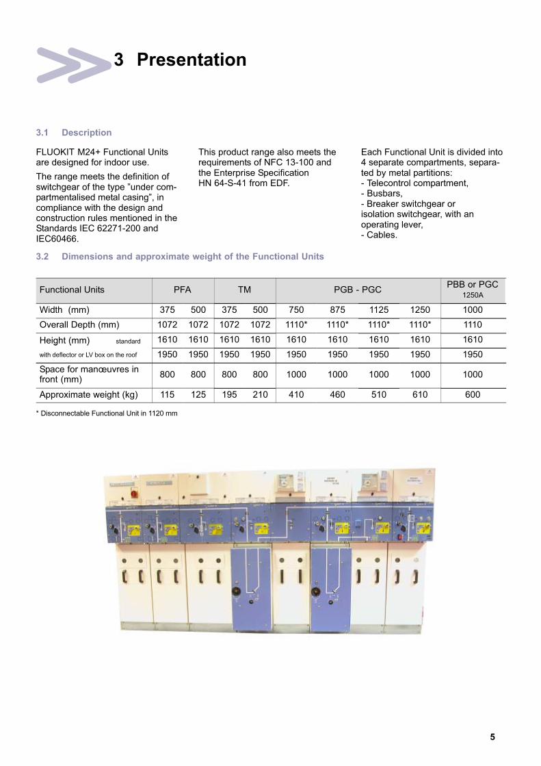
FLUOKIT M24+ Functional Unitsare designed for indoor use.
The range meets the definition ofswitchgear of the type "under com-partmentalised metal casing", incompliance with the design andconstruction rules mentioned in theStandards IEC 62271−200 andIEC60466.
This product range also meets therequirements of NFC 13−100 andthe Enterprise SpecificationHN 64−S−41 from EDF.
Each Functional Unit is divided into4 separate compartments, separa-ted by metal partitions:− Telecontrol compartment,− Busbars,− Breaker switchgear orisolation switchgear, with anoperating lever,− Cables.
3.2 Dimensions and approximate weight of the Functional Units
Functional Units PFA TM PGB − PGCPBB or PGC
1250A
Width (mm) 375 500 375 500 750 875 1125 1250 1000
Overall Depth (mm) 1072 1072 1072 1072 1110* 1110* 1110* 1110* 1110
Height (mm) standard 1610 1610 1610 1610 1610 1610 1610 1610 1610g ( )
with deflector or LV box on the roof 1950 1950 1950 1950 1950 1950 1950 1950 1950
Space for manœuvres infront (mm)
800 800 800 800 1000 1000 1000 1000 1000
Approximate weight (kg) 115 125 195 210 410 460 510 610 600
* Disconnectable Functional Unit in 1120 mm

6
3.3 Presentation of the Functional Units
IS (Switch−Disconnector)
0 Key
−�1 Busbar connection plates
−�2 ISR switch−disconnector
−�3 Upstream Earthing Switch
−�4 Upper fuse support shell
−�5 Cable connections shell
−�6 MV Fuse
−�7 Capacitive insulator
−�8 Lower fuse holder shell
−�9 Downstream Earthing Switch
−�10 Base plate in 4 elements
−�11 LV casing
−�12 Exhaust shaft
−�13 Overpressure valves
−�14 Earthing bar connection point
−�15 Access panel to the busbars
−�16 Mechanical control mechanism for the
switch
1
2
7
5
3
13
16
11
1920
2110
12
14
18
13
22
13
13
13
−�17 Circuit breaker mechanical control mechanism(BLR)
−�18 Voltage presence luminous indicators or interfacefor Voltage Detection System
−�19 Inspection window for checking the earthingswitch position
−�20 Earthing pin for installation of earthing block
−�21 Access panel to the cable compartment
−�22 ES location (LV capacitors)
−�23 Voltage transformers
−�24 Auxiliary contacts
−�25 Current transformers
−�26 Cable connection lugs
−�27 FP circuit breaker with interruption under SF6 gas
−�28 ISR locked in ‘Open’ position
−�29 Upper plugging−in clamps
−�30 Lower plugging−in clamps
−�31 HV Fuse
13
15

7
TM (Instrument Transformer)
1
2
23
6
3
8
13
14
4
2019
11
16
21
0
13
18
11
PF − PFA (Fuse Protection)
4
3
6
9
10
12
13
8
7
21
1920
2
114
13
16
22
13
13
13
13
12
24
15
15

8
27
26
13
17
21
2
1
11
12
16
13
13
25
1
28
PGC + current transformers + FP circuit breaker (General Cable Protection)
3
7
27
25
13
17
21
2
111
12
16
13
13
25
1
2
PGB + current transformers + FP circuit breaker (General Busbar Protection)
9
15
15

9
PGB disconnectable (General Busbar Protection) + FP circuit breaker
27
13
17
21
2
1 11
30
12
16
PGC disconnectable (General Cable Protection)+ current transformers and FP circuit breaker
3
29
18
27
13
2
1
30
3
29
23
13
25
1
31
+ 6 current transformers+ 6 current transformers+ 6 voltage transformers
RKF24
RKF24

10
4 Packaging − Handling − Storage
4.1 Transport − Delivery
The conditions and methods oftransport are defined with the cus-tomer, at the time of processing thecontract.
Packaging is dependent on theconditions of transport, storage andthe nature of the product beingtransported.
The Functional Unit must behandled and transported ver-
tically (position shown below).
4.2 Packaging for the Functional Units
� The packaging of a FunctionalUnit for road and rail transport:− fixed on to a wooden pallet orbound by hoops,− covered by plastic sheeting,− protection of the front face.
ÉÉÉÉÉÉÉ� The packaging of a Functional
Unit for air and maritimetransport: − under a heat−sealed coverwith bags of desiccant,− packed in wooden crates.
ËËËËËËËËËËËËËËËËËËËËËËËËËËËËËËËËËËËË
ËËËËËËËËËËËËËËËËËËËËËËËË
ËËËËËËËËËËËËËËËËËËËËËËËË
ËËËËËËËËËËËËËËËËËËËËËËËË
ËËËËËËËËËËËËËËËËËËËËËËËË
ÁÁÁÁÁÁÁ
ÁÁÁÁÁÁÁÁÁÁÁÁÁÁ
ÁÁÁÁÁÁÁÁÁÁÁÁÁÁ
� Status of the equipment ondelivery:
1. Load break switch "Open"2. Earthing switch "Closed".
1
2
4.3 The accessories package
Contains all elements required forlocating and connecting the Func-tional Units to busbar and cableconnections.
4.4 Reception/Acceptance
� Ensure that the materialdelivered is all there.
� Carry out a visual inspection ofthe Functional Units and movingparts.
� Verify that the accessories arepresent in accordance with theattached list.
� Check the characteristics shownon the name and rating plates,in relation to the initial order(see § 4.5).
In the event of an anomaly,inform and make the
necessary reserves with thetransporter.
The Functional Unit mustremain on its base, within its
original packaging during anystorage period and until it arrives atthe location of its installation.

11
4.5 Location of the technical data plates
1 2 3 1 2 3
� 1 − Technical characteristics.� 2 − Allocation to AMT customer
(references, order number, etc.).� 3 − Identification plate.
4.6 Handling
� Road and rail packaging (500kg max.): with the aid of ahand−operated lift truck.
� It is imperative that the forks ofthe truck are fully engagedacross the entire width of theFunctional Unit.
� Move the Functional Unit, byalways taking account of itscentre of gravity (marked on thepackaging).
ÉÉÉÉÉÉÉÉÉÉÉÉ
ÎÎÎÎÎÎÎÎÎÎÎÎÎÎÎÎÎÎÎÎÎÎÎÎÎÎÎ
� Air and maritime transportpackaging: Depending on theweight indicated on the crate.
� It is imperative that the forks ofthe truck are fully engagedthroughout the entire width ofthe crate.
� Move the Functional Unit, byalways taking account of itscentre of gravity (marked on thepackaging).
ÌÌÌÌÌÌÌÌÌÌÌÌÌÌÌÌÌÌÌÌÌÌÌÌ
� Pass 2 slings, each onesupporting 1,000 kg.
� Remove the lifting parts afterhandling (4 screws, 13 mmspanner).
1m min.

12
4.7 Storage conditions
Ensure that the material is suitablypackaged for the requirements ofthe planned storage period.
Preserve the equipment in its intactoriginal factory packaging.
Avoid leaving the material where itis likely to be subjected to large,
sudden temperature changes.
Ensure that there is a total absenceof aggressive vapours[e.g.: Sulphur Dioxide (SO2)].
ËËËËËËË
ËËËËËËËËËËËËËË
ËËËËËËË
ËËËËËËËËËËËËËË
ËËËËËËËËËËËËËË
ÁÁÁÁ
ÁÁÁÁ
ÁÁÁÁ
ÌÌÌÌÌÌÌÌÌÌÌÌÌÌÌÌÌÌÌÌÌÌÌÌÌÌÌÌ
Contact AREVA for anyderogations to these criteria
The area chosen for storage mustbe capable of protecting theproducts against possible damagedue to deterioration agents, suchas:
− Water− Water vapour− Saline atmosphere− All types of pollution− Micro−organisms.
+50° C
− 25° C
ÉÉÉ
4.8 Intervention levels
D e s c r i p t i o n Levels
Operations carried out by the Customer 1
Operations requiring specific training, carried out by an approved third party 2
Work to be carried out exclusively by AREVA 3
4.9 Specific recommendations for storage durations of less than 6 months
. Packaged under a plastic covering 1 2 3
Periodically carry out an inspection of the packaging X X X
When unpacking, check the mechanical operation by carrying out several operations* X X X
4.10 Specific recommendations for storage durations of between 6 and 12 months
. Protected by a heat−welded sheet, with bags of desiccant present 1 2 3
Periodically carry out an inspection of the packaging (check that, among other things, there are no holes) X X X
When unpacking: − check the operation of the switchgear by carrying out several operations* − X X
− Test the min. threshold level (AC, 85% rated Un; DC, 70% of Un ) for the electrical operation of the coils − X X
4.11 Specific recommendations for storage durations of between 12 and 24 months
. Protected by a heat−welded sheet, with a method of replacing the desiccant sachets 1 2 3
Periodically carry out an inspection of the packaging (check that, among other things, there are no holes) X X X
Periodically replace the bags of desiccant X X X
On removing the packaging: − light maintenance work − − X
− check the operation of the switchgear by carrying out several operations* − − X
− Test the min. threshold level (AC, 85% rated Un; DC, 70% of Un ) for the electrical operation of the coils − − X
* The pressure for an SF6 circuit breaker having travelled by air must be re−established to its rated value before anymechanical operation test.

13
5 Unpacking and installing the equipment
5.1 Type of Civil Engineering
The installation of a switchboardrequires a sufficiently flat and evenconcrete structure. The dressing ofa top coat of cement using a ruleshould eliminate any surface irregu-larities greater than 2 mm permetre.
A layout on iron supports for level-ling off is ideal as they will alsoserve as a guide for the adjustmentof the cement top coat.
The overall flatness of the supportsurface should not show up anydeflection greater than 6 mm throu-ghout the length of the switch-board.
5.2 Unpacking the Functional Units
Proceed with unpacking the Functio-nal Units only where they are to beinstalled on site.
Tools required: − Knife for road and rail transport packaging− Crowbar for air and sea transport packaging
Use suitable protective gloves forany handling operation.
5.3 Handling the Functional Unit
� Remove the protective plasticcover.
� Open the front panel:1 − lift the panel2 − pull the panel towards you.
1
2
� Special case of Functional Unitswithout an earthing switch.
Mark each panel inaccordance with the
corresponding Functional Unit.
For the PGB and PGCFunctional Units, remove
the wooden base without extrac-ting the circuit breaker.
� Remove the mechanical controlhood (see the correspondingmanual § 2.5).
� Loosen the 2 CHC bolts.� Pivot the lug towards the right.� Remove the front panel.
� Remove the 4 fixing screws(16 mm spanner) from thewooden base.
� Free the Functional Unit.
2 rear fixings
2 front fixings
� Place the Functional Unit on theground.
� Replace the front panel

14
� Four fixed slinging points areprovided for on the roof of eachFunctional Unit.
These lifting lugsare to be removed when
the Functional Units are in theimmediate proximity of theirdefinitive installation.
� Lift the Functional Unit by4 slings each one capable ofsupporting 1,000 kg.
� Respect the minimum carryingheight as shown on the abovediagram.
1 m min.
� Slide the Functional Unit along,using three cylindrical rollers of30 mm min. diameter.
� Thus moving it to its finalinstallation place.
5.4 Installation of a switchboard
Please refer to the instructions inthe Civil Engineering Guide(See § 2.5).
The limits of the civil engineeringlayout depends on the type andquantity of materials to be installed.
Position the cells whilst respectingminimum clearance distances infront of, behind and to each side ofthe switchboard.
5.5 Installing Functional Units
For a switchboard composed of 1to 8 Functional Units, it is advisableto begin installing the equipment onthe side of the room opposite theentrance.
For switchboards using more than8 units, start by installing the equip-ment to the middle of the switch-board.
5.6 Revalorizing packaging waste
After unpacking, the materialsremaining (cover, wooden floorpanel, etc) should be sorted andsent to the appropriate recyclingservices.
15
6 Installation
6.1 Installation of each Functional Unit
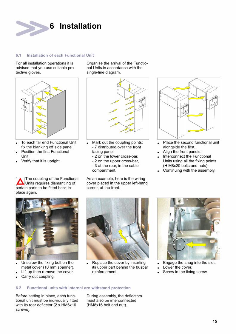
For all installation operations it isadvised that you use suitable pro-tective gloves.
Organise the arrival of the Functio-nal Units in accordance with thesingle−line diagram.
� To each far end Functional Unitfix the blanking off side panel.
� Position the first FunctionalUnit.
� Verify that it is upright.
� Mark out the coupling points:− 7 distributed over the frontfacing panel,− 2 on the lower cross−bar,− 2 on the upper cross−bar,− 3 at the rear, in the cablecompartment.
� Place the second functional unitalongside the first.
� Align the front panels.� Interconnect the Functional
Units using all the fixing points(H M8x20 bolts and nuts).
� Continuing with the assembly.
The coupling of the FunctionalUnits requires dismantling of
certain parts to be fitted back inplace again.
As an example, here is the wiringcover placed in the upper left−handcorner, at the front.
� Unscrew the fixing bolt on themetal cover (10 mm spanner).
� Lift up then remove the cover.� Carry out coupling.
� Replace the cover by insertingits upper part behind the busbarreinforcement.
� Engage the snug into the slot.� Lower the cover.� Screw in the fixing screw.
6.2 Functional units with internal arc withstand protection
Before setting in place, each func-tional unit must be individually fittedwith its rear deflector (2 x HM6x16screws).
During assembly, the deflectorsmust also be interconnected(HM8x16 bolt and nut).

16
6.3 Fixing the Functional Units to the floor
Fix the Functional Units to theground, by 2 points at the front and
2 points at the rear (H M12x30screws and flat washers with an out
side diameter of 32mm) or 2 pointsat the centre (PGC and PGB).
� 4 ground anchoring points(Fasteners not supplied).
� Each functional unit must imperatively be anchored to the floor by itsfour fixing points.
Front face of the switchboard: 3 or X Functional Units
PGB or PGC
70
60
6.4 Connection of the inter−Functional Units grounding circuit
� On the roof of the Functional Units, position and fix the earthing circuitbars (M8 washer + ES 8 washer + H M8 nut − 13 mm spanner).
1.5
� Close−up of the connection.
6.5 General switchboard earthing connection to the earthing spike of the building
This connection is via the Functio-nal Unit to the extreme right of theset (viewed from the front).
The copper connecting conductormust have a minimum cross sec-tion of 30 mm2 (fasteners not supplied).
Remove the plastic blankingpanel to connect the cable.
� Connector point for the earthingspike linkage cable.
4.9
� Pass the bolt through from the outside of the functional unit with the flatwasher already fitted to the head. Then, attach the cable, and from theinside of the functional unit ,the flat washer, the self−locking washer andfinally the M12 Nylstop nut (fixings not supplied).
4.9
H M12x35 bolts+ 2 flat washers+ self−locking washer+ M12 ‘Nylstop’ nut
Min. cross−section: 30 mm2
17
6.6 Standard busbar connections
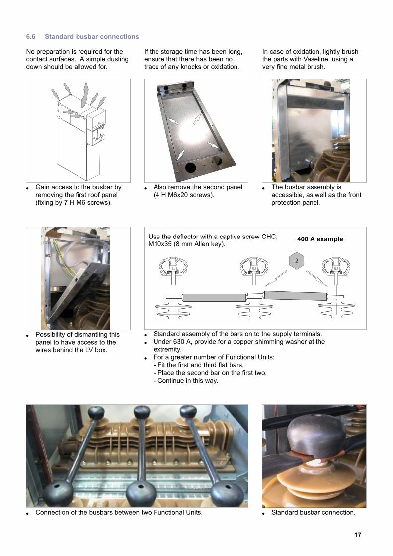
No preparation is required for thecontact surfaces. A simple dustingdown should be allowed for.
If the storage time has been long,ensure that there has been notrace of any knocks or oxidation.
In case of oxidation, lightly brushthe parts with Vaseline, using avery fine metal brush.
� Gain access to the busbar byremoving the first roof panel(fixing by 7 H M6 screws).
� Also remove the second panel(4 H M6x20 screws).
� The busbar assembly isaccessible, as well as the frontprotection panel.
� Possibility of dismantling thispanel to have access to thewires behind the LV box.
� Standard assembly of the bars on to the supply terminals.� Under 630 A, provide for a copper shimming washer at the
extremity.� For a greater number of Functional Units:
− Fit the first and third flat bars,− Place the second bar on the first two,− Continue in this way.
Use the deflector with a captive screw CHC,M10x35 (8 mm Allen key).
2
400 A example
� Connection of the busbars between two Functional Units. � Standard busbar connection.
18
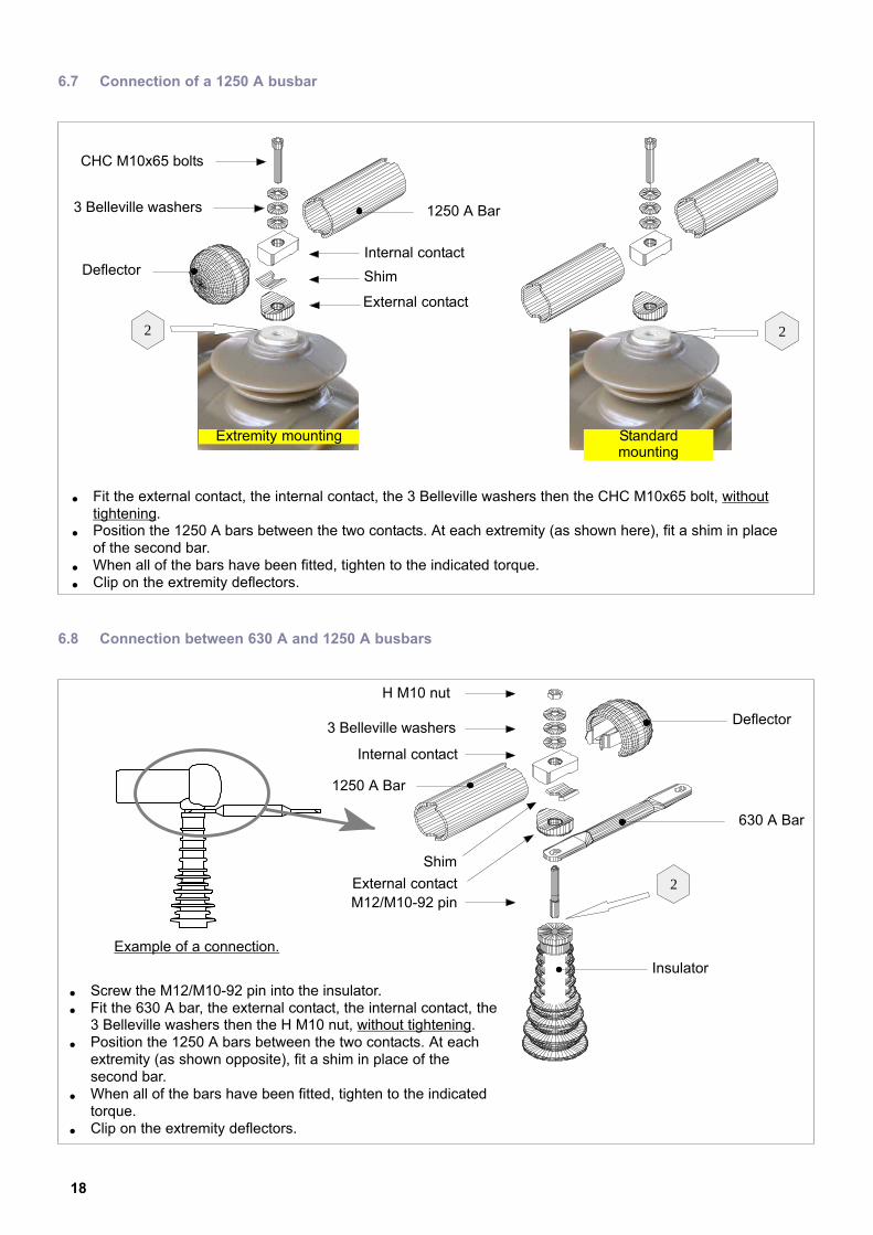
6.7 Connection of a 1250 A busbar
� Fit the external contact, the internal contact, the 3 Belleville washers then the CHC M10x65 bolt, withouttightening.
� Position the 1250 A bars between the two contacts. At each extremity (as shown here), fit a shim in placeof the second bar.
� When all of the bars have been fitted, tighten to the indicated torque.� Clip on the extremity deflectors.
Deflector
2
1250 A Bar
2
CHC M10x65 bolts
3 Belleville washers
Internal contact
Shim
External contact
Extremity mounting Standardmounting
6.8 Connection between 630 A and 1250 A busbars
� Screw the M12/M10−92 pin into the insulator.� Fit the 630 A bar, the external contact, the internal contact, the
3 Belleville washers then the H M10 nut, without tightening.� Position the 1250 A bars between the two contacts. At each
extremity (as shown opposite), fit a shim in place of thesecond bar.
� When all of the bars have been fitted, tighten to the indicatedtorque.
� Clip on the extremity deflectors.
Deflector
2
1250 A Bar
H M10 nut
3 Belleville washers
Internal contact
Shim
External contact
630 A Bar
M12/M10−92 pin
Insulator
Example of a connection.
19
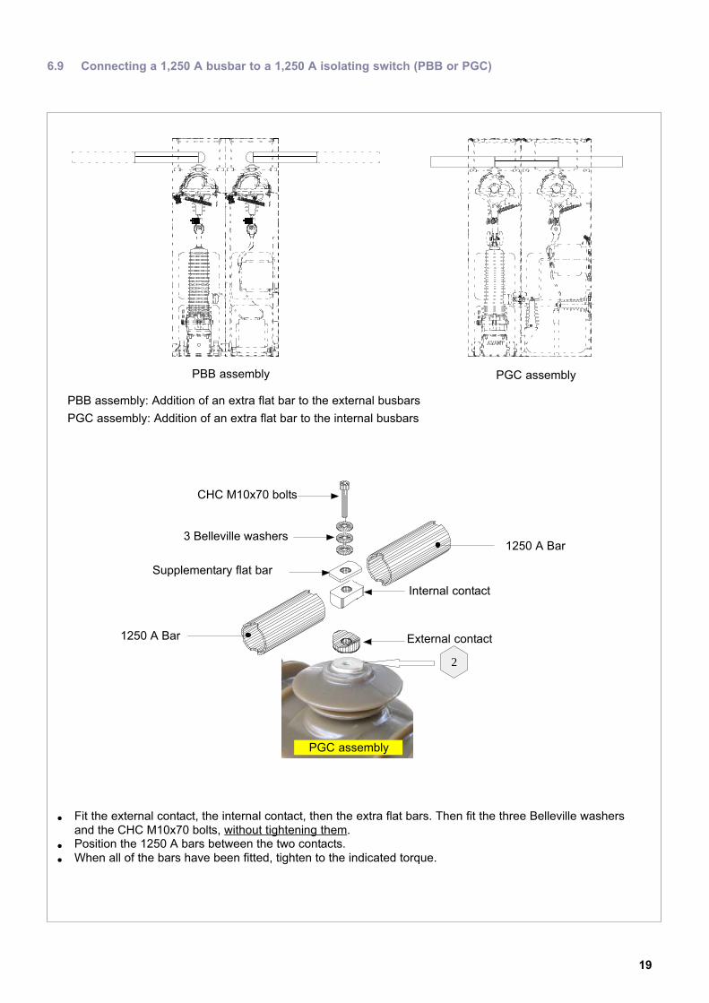
6.9 Connecting a 1,250 A busbar to a 1,250 A isolating switch (PBB or PGC)
� Fit the external contact, the internal contact, then the extra flat bars. Then fit the three Belleville washersand the CHC M10x70 bolts, without tightening them.
� Position the 1250 A bars between the two contacts.� When all of the bars have been fitted, tighten to the indicated torque.
1250 A Bar
2
CHC M10x70 bolts
3 Belleville washers
Internal contact
Supplementary flat bar
External contact
PGC assembly
PBB assembly PGC assembly
PBB assembly: Addition of an extra flat bar to the external busbars
PGC assembly: Addition of an extra flat bar to the internal busbars
1250 A Bar
20
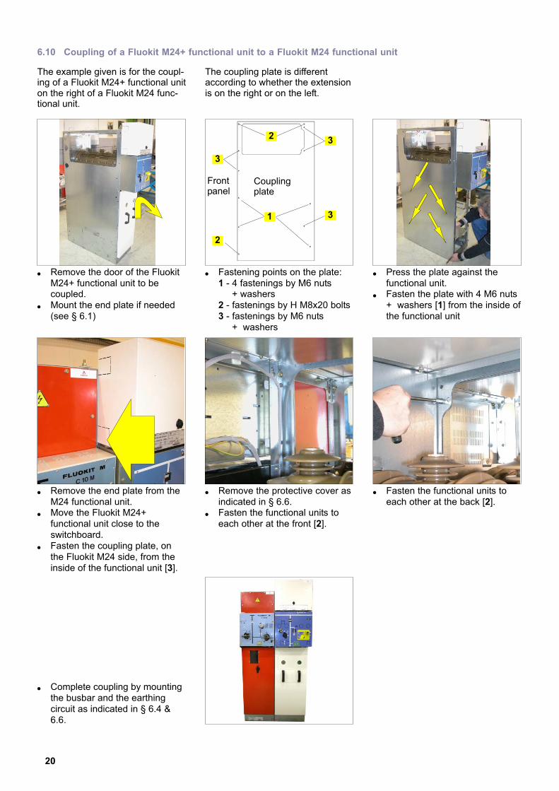
6.10 Coupling of a Fluokit M24+ functional unit to a Fluokit M24 functional unit
The example given is for the coupl-ing of a Fluokit M24+ functional uniton the right of a Fluokit M24 func-tional unit.
The coupling plate is differentaccording to whether the extensionis on the right or on the left.
� Remove the door of the FluokitM24+ functional unit to becoupled.
� Mount the end plate if needed(see § 6.1)
� Fastening points on the plate:1 − 4 fastenings by M6 nuts + washers2 − fastenings by H M8x20 bolts3 − fastenings by M6 nuts + washers
1
23
3
3
2
Frontpanel
Couplingplate
� Press the plate against thefunctional unit.
� Fasten the plate with 4 M6 nuts+ washers [1] from the inside ofthe functional unit
� Remove the end plate from theM24 functional unit.
� Move the Fluokit M24+functional unit close to theswitchboard.
� Fasten the coupling plate, onthe Fluokit M24 side, from theinside of the functional unit [3].
� Remove the protective cover asindicated in § 6.6.
� Fasten the functional units toeach other at the front [2].
� Fasten the functional units toeach other at the back [2].
� Complete coupling by mountingthe busbar and the earthingcircuit as indicated in § 6.4 &6.6.
21
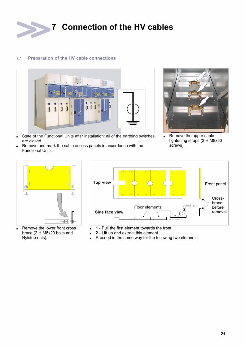
7 Connection of the HV cables
7.1 Preparation of the HV cable connections
� State of the Functional Units after installation: all of the earthing switchesare closed.
� Remove and mark the cable access panels in accordance with theFunctional Units.
� Remove the upper cabletightening straps (2 H M8x50screws).
� Remove the lower front crossbrace (2 H M8x20 bolts andNylstop nuts).
1
� 1 − Pull the first element towards the front.� 2 − Lift up and extract this element.� Proceed in the same way for the following two elements.
Side face view
Floor elements
Front panel
Cross−bracebeforeremoval
Top view
2

22
7.2 Connection instructions
− Use short cable terminations of the EUI−C type (with shells). They are compulsoryfor Functional Units PF − PFA − PGC− The building of the extremity (other than AREVA supply) must be carried out inaccordance with the manufacturer’s instructions.− The earthing braid for each cable must always exit above the bottom plate and theclamping collar.
− Leave 40mm of free clearance on the lug barrel for fitting the grounding clamp.− Ensure the correct orientation of the contact plate before crimping it.− There must be no tension on the cable.
Never stick any phase markers to the cable end reassemblies−−> decrease in the dielectric strength and degradation over time.− Never clamp the cable by its cable end.− Never leave a washer in incompatible material between the lug and the connectingplate.
7.3 Preparation of the cables
ÄÄÄÄÄÄÄÄ
� Pull out each cable from theopening via the front of theFunctional Unit to make up theextremity.
� Cut out each grommet to thediameter of the cable.
� Fit the grommet on to its cable.
� Example of a connectionterminating in IS.
� Example of a connectionterminating in PF.

23
7.4 Connection of an IS Functional Unit
0 Legend for § 7.4 and 7.5
−�1 Round lug
−�2 Deflector
−�3 H M12 nut
−�4 Belleville Washer
−�5 Flat washer
−�6 Rectangular lug(50mm x 48mm max.)
−�7 Copper spacer (notsupplied).
−�8 H M8 nut
� Lift off the deflector, theH M12 nut and the two washersfor each point.
� Connection is made by a roundor rectangular lug. In this lastcase, axis of the hole must be20 mm max. from the upperside de the lug.
Round lug connection
� Fit the lug which must hold firmagainst the contact plate.
� Fit the flat washer� Fit the Belleville washer� Screw in and tighten the nut to
the indicated torque (18 mmspanner).
� Clip on the deflector.
15
2
34
4.9
Rectangular lug connection
� Fit in place the spacer incopper.
� Position and hold firm therectangular lug.
� Fit the flat washer.� Fit the Belleville washer.� Screw in and tighten the nut to
the indicated torque (18 mmspanner).
� Clip on the deflector.
67 4.9
Ø 13mmØ 28mm
th. =12mm
7
20
7.5 Connection of a PF or PFA Functional Unit
� The connecting point is to befound below the fuse’s lowersupport.
� Begin the connections by thecable at the back.
� Proceed in the same way as forthe IS unit (§ 7.4).
� Remove the H M8 nut and thetwo washers from each point.
15
84
1.5
� Connection is made by a roundlug.
� There is no deflector.

24
7.6 Clamping the cables and connection of the screen braids
� Place the second floor panelelement.
� Fit the grommet firmly.
� Adapt the cable terminal straps(see further on) and tighten thenuts lightly (13 mm spanner).
cable < 150 mm2
cable > 150 mm2
� Repeat these operations for theother two cables.
� Re−assemble the lower frontcross−brace.
For the FunctionalUnits PF /PFA,ensure that the cables
exert no traction on the supportcross−brace. Check that afterinstallation the fuses can becorrectly fitted in place, and thatthe contacts are sufficientlycovered (See § 7.9).
7.7 Connection in a PGC or IS Functional Unit equipped with current transformers
� State on delivery. � 1 − Position the lug and thecable.
� 2 − Fit the flat washer, then theself−locking washer.
� 3 − Screw in and tighten theH M10 nut to the indicatedtorque.
3 2
3
1
7.8 Earthing the screen braids
� Connection point for the threeHV cable screen braids.

25
7.9 Fitting the fuses on to the PF−PFA Functional Units
Prior to fitting, a fuse statustest must be carried out.
� For a striker fuse of the FN orFD type (DIN), remove theprotective label.
� For FNw and FDw fuses thislabel must remain on.
� For other fuses, follow themanufacturer’s instructions.
Position the strikertowards the top.
� Lift the lid of the upper currentsupply terminal.
� Hold the fuse by its upper part.
� Fit the fuse into the lower shell.
� Push the fuse home into theupper current supply terminal.
� Ensure that the upper contactsare correctly covered. The 4blades of the jaw must holdfirm over all of their surfacecontact, on the fuse cup.
� Ensure the correct refitting ofthe lid and the position of thelabel: it must be visible from thefront face panel.
� The fuse is now in place.

26
7.10 The sensors (rings) for fault detection and signalling
� Sensor of the ring with bladestype.
� Example of the assembly of therings for delivery.
7.11 Mounting the rings
Position and fit each ring, centredperpendicularly to the cable.
The rings must be positionedbelow the cable end of each
cable. Under no circumstancesmust they be on the cable end.
Insulate the earthing braid.
Pass the braid back, in the reversedirection to the cable, into the ring
Connect together the 3 cablescreen braids, on to the earthingcircuit (H M8x30 bolt, 13 mm span-ner).
1.5
� Each braid must pass back in thereverse direction to the cable intothe ring.
� Connect together the 3 cablescreen braids to the earthingcircuit.
7.12 Special instructions at the end of the connections
After any work in the cablecompartment, replace the
front face panel.
Ensure that all of the connec-tions, busbar couplings,
cables, earthing circuits and lowvoltage circuits have been correctlycarried out.
Ensure that the fuses havebeen correctly fitted in place,
and the presence of access panelsto the interior of the FunctionalUnits.

27
8 Connection of the low voltage circuits
8.1 Marking the functional unit on the LV box cover
� On the front panel, the covermay bear an ID plate –identifying the functional unit.
� If this is the case, thisdescription must be noted onthe label within the box.
� The cover is thus permanentlylinked to a single functional unit.
8.2 Motorised remote control interface for the switches [option]
� Front face of the box. � Neutralization switch markedUFA.
� The cable connection isdelivered with a connectormarked UFA, and a packet oflabels.
Packet oflabels
Connector

28
8.3 Connection of the "Metering" low voltage wiring to the PGB Functional Unit
Material to be provided:Lugs for 6 mm diameter fixings,− 1.5 mm2 cross section (TM),− 2.5 or 6 mm2 cross section(PGB).
� Front view: Connection is madefrom the top, via the rear of theLV box.
� Side face view: connection fromthe top.1 − Location of the terminal block.2 − Wiring to be carried out onsite. Provide for an additionallength of 4 m of wire.
1
2
8.4 Connection of the "Metering" low voltage wiring to the TM Functional Unit
� Front view: Connection is madefrom the top, via the rear of theLV box.
� Side face view: connection fromthe top.1. Location of the terminalblock.2. Wiring to be carried out onsite. Provide for an additionallength of 4 m of wire.
2
1
An extremity blanking piecefor the terminal block cover is
delivered mounted on each ISFunctional Unit.It can be dismantled then reassem-bled on to another Functional Unit,depending on the layout of theswitchboard.
29
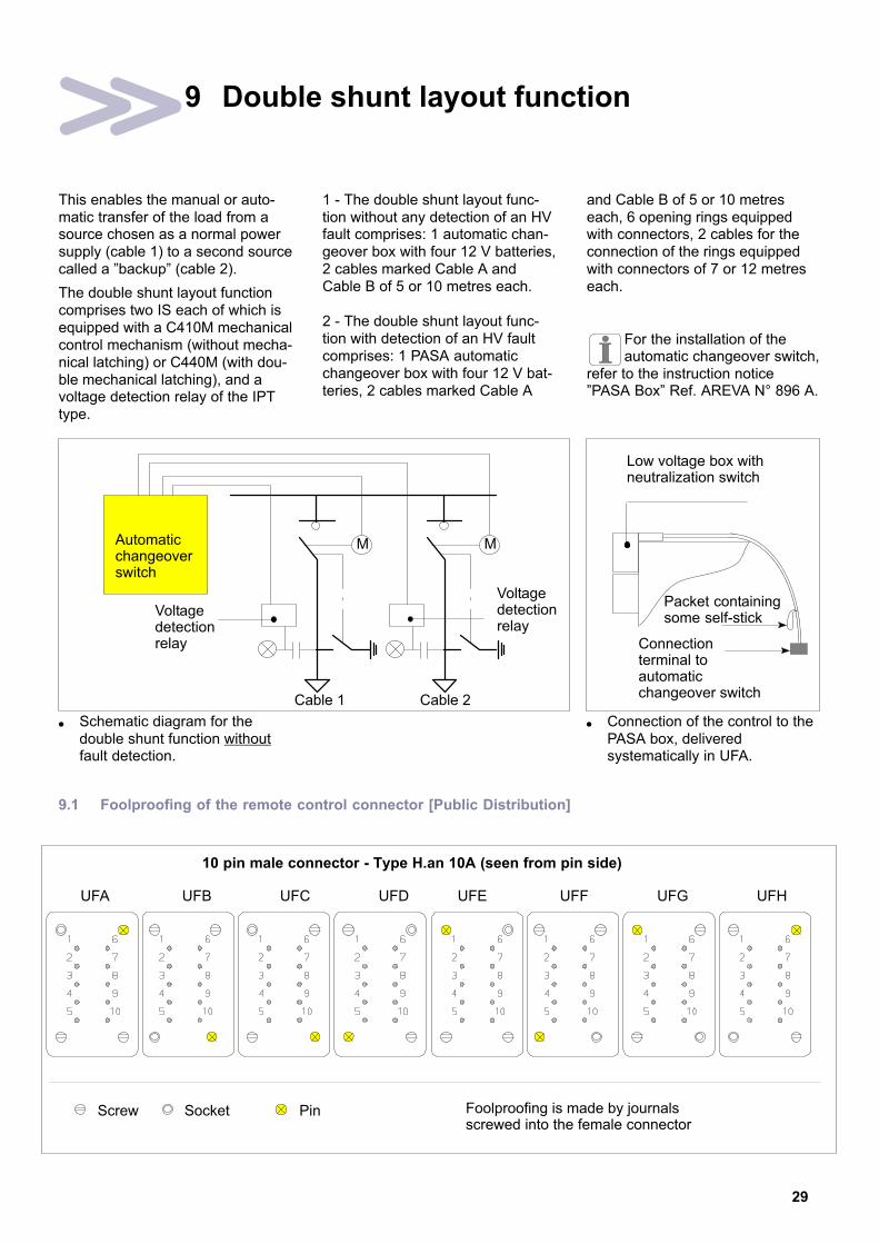
9 Double shunt layout function
This enables the manual or auto-matic transfer of the load from asource chosen as a normal powersupply (cable 1) to a second sourcecalled a "backup" (cable 2).
The double shunt layout functioncomprises two IS each of which isequipped with a C410M mechanicalcontrol mechanism (without mecha-nical latching) or C440M (with dou-ble mechanical latching), and avoltage detection relay of the IPTtype.
1 − The double shunt layout func-tion without any detection of an HVfault comprises: 1 automatic chan-geover box with four 12 V batteries,2 cables marked Cable A andCable B of 5 or 10 metres each.
2 − The double shunt layout func-tion with detection of an HV faultcomprises: 1 PASA automaticchangeover box with four 12 V bat-teries, 2 cables marked Cable A
and Cable B of 5 or 10 metreseach, 6 opening rings equippedwith connectors, 2 cables for theconnection of the rings equippedwith connectors of 7 or 12 metreseach.
For the installation of theautomatic changeover switch,
refer to the instruction notice"PASA Box" Ref. AREVA N° 896 A.
� Schematic diagram for thedouble shunt function withoutfault detection.
Voltagedetectionrelay
Automaticchangeoverswitch
M M
Voltagedetectionrelay
Cable 1 Cable 2
� Connection of the control to thePASA box, deliveredsystematically in UFA.
Low voltage box withneutralization switch
Connectionterminal toautomaticchangeover switch
Packet containingsome self−stick
9.1 Foolproofing of the remote control connector [Public Distribution]
UFA UFB UFC UFD
Screw Socket Foolproofing is made by journalsscrewed into the female connector
Pin
10 pin male connector − Type H.an 10A (seen from pin side)
UFE UFF UFG UFH
30
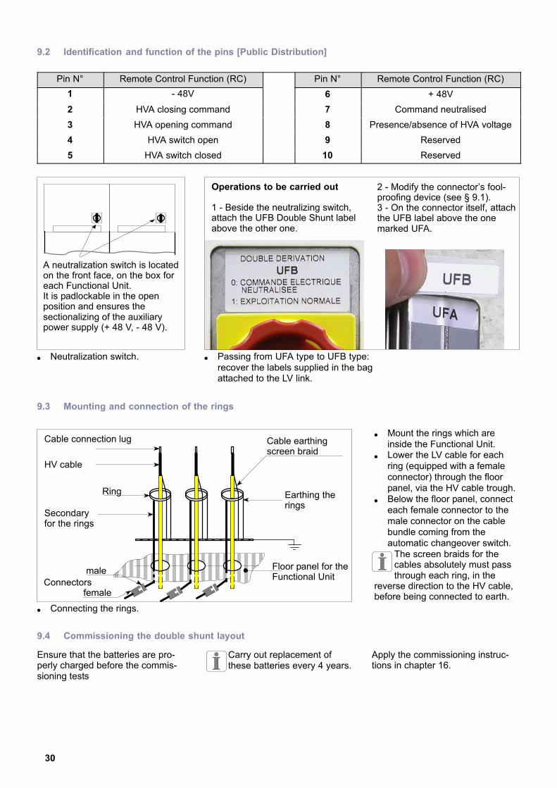
9.2 Identification and function of the pins [Public Distribution]
Pin N° Remote Control Function (RC) Pin N° Remote Control Function (RC)
1 − 48V 6 + 48V
2 HVA closing command 7 Command neutralised
3 HVA opening command 8 Presence/absence of HVA voltage
4 HVA switch open 9 Reserved
5 HVA switch closed 10 Reserved
A neutralization switch is locatedon the front face, on the box foreach Functional Unit.It is padlockable in the openposition and ensures thesectionalizing of the auxiliarypower supply (+ 48 V, − 48 V).
� Neutralization switch. � Passing from UFA type to UFB type:recover the labels supplied in the bagattached to the LV link.
Operations to be carried out
1 − Beside the neutralizing switch,attach the UFB Double Shunt labelabove the other one.
2 − Modify the connector’s fool-proofing device (see § 9.1).3 − On the connector itself, attachthe UFB label above the onemarked UFA.
9.3 Mounting and connection of the rings
male
ËËËËËËËËËËËËËËËËËËËËËËËËËËËËËËËËËËËË
� Connecting the rings.
ÂÂÂÂÂÂÂÂÂ
Cable connection lug Cable earthingscreen braid
Ring
Secondaryfor the rings
female
Earthing therings
HV cable
Floor panel for theFunctional Unit
Connectors
� Mount the rings which areinside the Functional Unit.
� Lower the LV cable for eachring (equipped with a femaleconnector) through the floorpanel, via the HV cable trough.
� Below the floor panel, connecteach female connector to themale connector on the cablebundle coming from theautomatic changeover switch.
The screen braids for thecables absolutely must passthrough each ring, in the
reverse direction to the HV cable,before being connected to earth.
9.4 Commissioning the double shunt layout
Ensure that the batteries are pro-perly charged before the commis-sioning tests
Carry out replacement ofthese batteries every 4 years.
Apply the commissioning instruc-tions in chapter 16.

31
10 Normal/Backup function
10.1 Principle
This function provides an automatictransfer of the load from the "Nor-mal" source to a "Backup" source inthe event of a loss in voltage fromthe former. It will automaticallyreturn to the "Normal" source oncethe voltage has been definitivelyrestored.
Between the 2 Functional Units cal-led Cable 1 and Cable 2, the selec-tion of the "Normal" source is madeby a selector switch.
A mechanical function interlock pre-vents the 2 sources from beingconnected in parallel.
10.2 Presentation
� IS Functional Units are coupledtogether and equipped withC440M mechanical controlmechanisms.N.B.: Shown without theelectrical energy unit.
Câble 1 Câble 2
� Front face of the LV box.1. "Normal" source selectorswitch. It is padlockable in the 3positions and must be set to 0before any maintenanceoperation.2. Operations counter.Increments a unit whenever theNormal−Backup source carriesout a complete operating cycle.When the operations counter islocated between 2 units, theNormal−Backup operates on the"Backup" source.
12
� The LV box groups together thechangeover automatic controls. 3. Protection fuses.4. Automatic changeovercontrol relays.5. RPT voltage detection relays.6. Connections terminal block.
543
6

32
� Protection fuses. � Changeover relays.The K4 relay is set for aminimum voltage
disappearance time on thebusbar = 0.3s. It is possible toadjust this time depending onthe network’s constraints.
� RPT voltage detection relays(one per Functional Unit). Thereference voltage is taken onthe L2 phase, at the voltagesocket level.
10.3 Mechanical interlocking forbidding connection in parallel
� The 2 Functional Units aresupplied coupled together,connected by mechanicalinterlocking.
� Location of the passage of thelinkage rods between the 2mechanical controls.
� Covers removed.� The two C440M mechanical
control mechanisms are notinterchangeable between eachother.

33
11 Operating accessories and instructions
11.1 Reminder
The Functional Unit is deliveredwith the:− load break switch "Open,"− earthing switch "Closed".
The manoeuvres for manual opera-tion are made without any specialeffort.
If cubicle de−energized: the wea-ring of gloves is not compulsory.If cubicle is energised: respect andapply the operating and safety ins-tructions in force on the site.
� The accessories (fuses, levers)are stored in the wall storagerack (see § 11.2).
� A single operating lever, for theload break switch and theearthing switch.
2
1
� Place the lever in position:1 − Lever pin in the main shaft manoeuvring shaft,2 − Secondary pin in the notch.
1
2
11.2 Wall storage rack (optional)
� If necessary, cut out the upperpart to house the box containingthe fuses.
� Under the wall storage rack, fix the(optional) support for the rolling floorsupplied in the case of a withdrawablePG Functional Unit.
Fixings
Fixings WithdrawablePG rolling floor
375 m
m m
in.
11.3 Operation of a Functional Unit equipped with a C410−C410S−C410M control
See the instructions in the manual(See § 2.5).
11.4 Operation of a Functional Unit equipped with a C430−C430M control
See the instructions in the manual(See § 2.5).

34
11.5 Operation of a Functional Unit equipped with a C440−C440M control
See the instructions in the manual(See § 2.5).
11.6 Cable testing
� This test is to be carried outbefore commissioning theFunctional Unit.
� Afterwards, it will also becarried out regularly by theSafety Organisations.
� The load break switch must beopen, the earthing switchclosed.
The opening of theearthing switch, door panel
removed, is forbidden, by theinternal mechanical locks"function", the closing of the switch. � Remove the door panel.
� Using the right hand, turn thepadlockable button andmaintain it there.
� With the left hand, insert theoperating lever.
� With both hands, grasp thelever by its extremities.
� Lower the lever towards the left.The earthing switch is nowopen.
� After the tests, close theearthing switch again andreplace the door panel inposition.
11.7 Installing the removable earthing switch device
� The earthing switch being closedand the door panel having beenremoved (see § 11.6), check forthe absence of voltage with thevoltage detection pole.
� Fix the main jaws of the earthingblock to the earthing pin
� Fit in place and tighten, one afterthe other, the earthing block’sclamps to the cables’ lug barrels(40 mm of space in reserve). Usethe insulating pole provided forthis.
The position of the earthingblock should forbid the refittingin place of the door panel.
After the tests, remove theearthing switch device,and replace the door panelin position.
Earthing pin
Cable lugs
Insulating pole

35
12 Operating the TM Functional Unit
12.1 Operating manoeuvres for the TM Functional Unit
� Door panel in place and locked,close the fuses of thesecondary circuit for the voltagetransformers.
� Fit the protective cover in placeagain and lock it.
� There is a small pad in the topleft hand corner used to apply alead seal to the box.
ÎÎ
� The rest of the manoeuvres areidentical to those of the ISFunctional Unit (refer to theinstruction manual, see § 2.5).

36
13 Operating the PGB Functional Unit
13.1 Opening the upstream and downstream earthing switches
� Using the right hand, turn thepadlockable button andmaintain it there.
� Insert the lever.
� Make the rod slide upwardsthen grip the lever by both of itsextremities.
� Lower the lever towards the left.
� The earthing switches are nowopen.
� Remove the lever.
13.2 Closing the load break switch
� Using the left hand, turn thepadlockable button andmaintain it there.
� Insert the lever.
� Make the rod slide upwardsthen grip the lever by both of itsextremities.
� Lower the lever towards theright.
� The switch is now closed.� Remove the lever.

37
13.3 Closing the circuit breaker
� Lock the load break switch andremove the key.
� The circuit breaker is locked inthe "tripped" position.
� Insert the key and turn it: Thecircuit breaker is now unlocked.
� Using the crank handle, resetthe BLR mechanical controlmechanism.
� Turn the handling button toclose the circuit breaker.
� Circuit breaker closed, reset theBLR so as to have a reserve ofenergy available.
13.4 De−energizing a PGB Functional Unit
Proceed with operations in thereverse order to those describedin § 13.1 to 13.3.
38
14 Operating the PGC Functional Unit
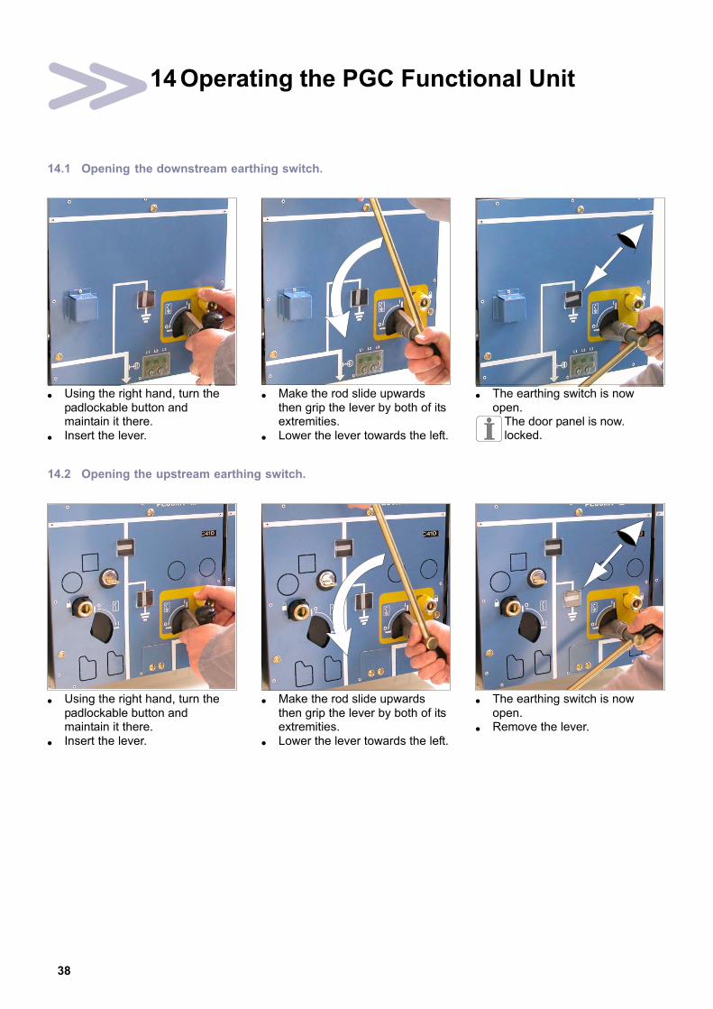
14.1 Opening the downstream earthing switch.
� Using the right hand, turn thepadlockable button andmaintain it there.
� Insert the lever.
� Make the rod slide upwardsthen grip the lever by both of itsextremities.
� Lower the lever towards the left.
� The earthing switch is nowopen.
The door panel is now.locked.
14.2 Opening the upstream earthing switch.
� Using the right hand, turn thepadlockable button andmaintain it there.
� Insert the lever.
� Make the rod slide upwardsthen grip the lever by both of itsextremities.
� Lower the lever towards the left.
� The earthing switch is nowopen.
� Remove the lever.

39
14.3 Closing the load break switch
� Using the left hand, turn thepadlockable button andmaintain it there.
� Insert the lever.
� Make the rod slide upwardsthen grip the lever by both of itsextremities.
� Lower the lever towards the right.
� The switch is now closed.� Remove the lever.
14.4 Closing the circuit breaker
� Lock the load break switch andremove the key.
� The circuit breaker is locked inthe "tripped" position.
� Insert the key and turn it: Thecircuit breaker is now unlocked.
� Using the crank handle, resetthe BLR mechanical controlmechanism.
� Turn the handling button toclose the circuit breaker.
� Circuit breaker closed, reset theBLR so as to have a reserve ofenergy available.
14.5 De−energizing a PGC Functional Unit
Proceed with operations in thereverse order to those described in§ 14.1 to 14.4.
40
15 Locking−out and locking operations
15.1 Functional mechanical interlocks
M24+ functional interlocks areequipped with internal mechanicalinterlocks, called "functional",intended to avoid any kind of ope-rating error.
It is necessary to know these inter-locks in order to operate the switch-gear correctly.
INTERLOCKING FUNCTION FUNCTIONING
��Between the cable access paneland the earthing switch
��It is impossible to completely openthe earthing switch if the door panelis not in place.
−�The fitting of the access panel tothe cable compartment unlocks theearthing switch.
��Earthing switch open, it is impos-sible to remove the cable accesspanel.
−�The opening of the earthing switchlocks the door panel in place.
��Between the earthing switch andthe load break switch
��The partial opening of the earthingswitch (door panel removed) forbidsthe closing of the load break switch.
�The complete opening of the ear-thing switch (door panel in place)authorises the operation of the loadbreak switch.
− Whenever the cable access panelis removed, it is impossible to openthe earthing switch, but a mechani-cal interlock forbids operating theswitch.
− The presence of the panel freesthis interlocking.
��Load break switch closed, it isimpossible to close the earthingswitch.
−�A mechanical interlock forbids thisoperation.
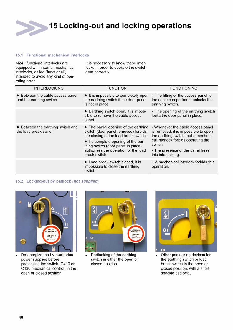
15.2 Locking−out by padlock (not supplied)
� De−energize the LV auxiliariespower supplies beforepadlocking the switch (C410 orC430 mechanical control) in theopen or closed position.
� Padlocking of the earthingswitch in either the open orclosed position.
� Other padlocking devices forthe earthing switch or loadbreak switch in the open orclosed position, with a shortshackle padlock..
41
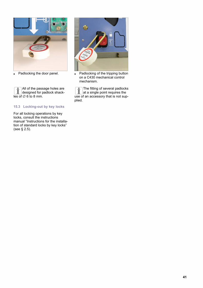
� Padlocking the door panel. � Padlocking of the tripping buttonon a C430 mechanical controlmechanism.
All of the passage holes aredesigned for padlock shack-
les of ∅ 6 to 8 mm.
The fitting of several padlocksat a single point requires the
use of an accessory that is not sup-plied.
15.3 Locking−out by key locks
For all locking operations by keylocks, consult the instructionsmanual "Instructions for the installa-tion of standard locks by key locks"(see § 2.5).
42
16 Commissioning
16.1 Reminder
Prior to shipping, FLUOKIT M24+Functional Units are mechanicallyand electrically tested.
If the equipment has been stored ina damp location, it is recommendedthat the room be heated and theheating elements be energised fora period of 24 hours prior to instal-lation of the switchboard.
Also check the leaktight sealing inthe room and the cable troughs.
16.2 Inventory of tools and accessories on completion of work
Recover, verify and tidy away allassembly tools and objects notrequired in the switchboard.
Return the Functional Unit’s andCircuit Breakers’ operating acces-sories to their respective storagepositions.
Attach the M24+ technical instruc-tion manual in a visible locationwithin the room.
16.3 Pre−commissioning information
Respect the General Safety Ins-tructions booklet for ElectricalApplications and the particularregulations for the network concer-ned with regard to locking−out pro-cedures.
Record the serial numbers andidentifying marks on equipment andswitchgear while they are accessi-ble. Tests and inspections havealready been carried out in the fac-tory.
Refer to the drawings and diagramssupplied with the equipment. Theydescribe the functionalitiesemployed to carry out the level ofoperation required.
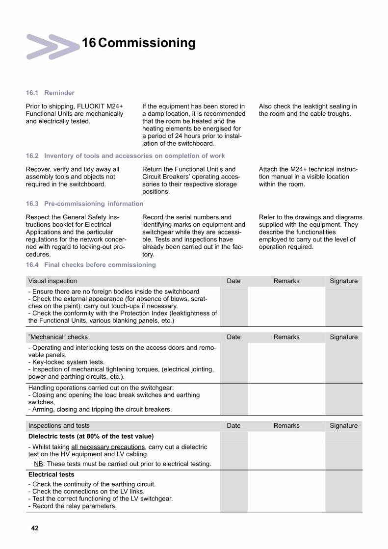
16.4 Final checks before commissioning
Visual inspection Date Remarks Signature
− Ensure there are no foreign bodies inside the switchboard− Check the external appearance (for absence of blows, scrat-ches on the paint): carry out touch−ups if necessary.− Check the conformity with the Protection Index (leaktightness ofthe Functional Units, various blanking panels, etc.)
"Mechanical" checks Date Remarks Signature
− Operating and interlocking tests on the access doors and remo-vable panels.− Key−locked system tests.− Inspection of mechanical tightening torques, (electrical jointing,power and earthing circuits, etc.).
Handling operations carried out on the switchgear:− Closing and opening the load break switches and earthing switches,− Arming, closing and tripping the circuit breakers.
Inspections and tests Date Remarks Signature
Dielectric tests (at 80% of the test value)
− Whilst taking all necessary precautions, carry out a dielectrictest on the HV equipment and LV cabling.
NB: These tests must be carried out prior to electrical testing.
Electrical tests
− Check the continuity of the earthing circuit.− Check the connections on the LV links.− Test the correct functioning of the LV switchgear.− Record the relay parameters.

43
State of the switchgear Date Remarks Signature
− Ensure that all the load break switches, circuit breakers andearthing switches are open and the access panels to the cablesand the busbars are in place.− In accordance with the fuse supplier instructions, ensure thatthe striker covers on the voltage transformer fuses have beenremoved.
16.5 Energising the "Incoming" Functional Unit
1
2
The "voltage presence" indicationis ensured in conformity with theinstructions in IEC61958.
To each of the 3 phases L1, L2 andL3 there is a correspondingflashing indicator [1].
A connection point [2], for eachphase, is accessible on the frontface of the luminous indicator inorder to connect the phasecomparator.
The indication of a VPIS, by itself,is insufficient to ensure that thesystem is de−energized: if theoperating rules demand it, then theappropriate voltage detectors mustbe used to that effect, incompliance with IEC61243−5.
Energise the busbar. To do this,close the load break switch(See § 11).
16.6 Energising a second ’Incoming’ Functional Unit, supplied from the same source
Energize the cables. Check that the neon lights of thevoltage presence indicator light up.
Check the phase balance (See §16.7) prior to commissioning.
16.7 Control of phase balance with a VPIS voltage presence indicator (in accordance with IEC61958)
� Connect the two phasecomparator cables to the2 phases of a single functionalunit.The light should light up: thecomparator is now working.
1 − Phase comparator test
L1 L2 L3
� Phases balanced: Light out� Phases out of sequence:
Light on
� Ensure the phase balance usinga phase comparator checkedIf the phases are out ofsequence, inspect the cableconnections.
2 − Verification of phase balance
L1 L2 L3 L1 L2 L3
The Fluokit M24+ phase com-parator is an optional extra. If
no comparator is available, as asecondary measure, use the Fluo-kit M24 phase comparator for anequivalent voltage.
16.8 Energizing the switchboard
Close the breaking devices on the"Incoming" functional units.
Energize the "Outgoing" FunctionalUnits.
Close the corresponding breakingdevices.
44
17 Maintenance
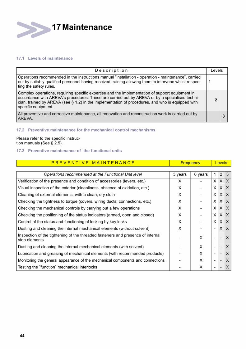
17.1 Levels of maintenance
D e s c r i p t i o n Levels
Operations recommended in the instructions manual "installation − operation − maintenance", carriedout by suitably qualified personnel having received training allowing them to intervene whilst respec-ting the safety rules.
1
Complex operations, requiring specific expertise and the implementation of support equipment inaccordance with AREVA’s procedures. These are carried out by AREVA or by a specialised techni-cian, trained by AREVA (see § 1.2) in the implementation of procedures, and who is equipped withspecific equipment.
2
All preventive and corrective maintenance, all renovation and reconstruction work is carried out byAREVA.
3
17.2 Preventive maintenance for the mechanical control mechanisms
Please refer to the specific instruc-tion manuals (See § 2.5).
17.3 Preventive maintenance of the functional units
P R E V E N T I V E M A I N T E N A N C E Frequency Levels
Operations recommended at the Functional Unit level 3 years 6 years 1 2 3
Verification of the presence and condition of accessories (levers, etc.) X − X X X
Visual inspection of the exterior (cleanliness, absence of oxidation, etc.) X − X X X
Cleaning of external elements, with a clean, dry cloth X − X X X
Checking the tightness to torque (covers, wiring ducts, connections, etc.) X − X X X
Checking the mechanical controls by carrying out a few operations X − X X X
Checking the positioning of the status indicators (armed, open and closed) X − X X X
Control of the status and functioning of locking by key locks X − X X X
Dusting and cleaning the internal mechanical elements (without solvent) X − − X X
Inspection of the tightening of the threaded fasteners and presence of internalstop elements
− X − − X
Dusting and cleaning the internal mechanical elements (with solvent) − X − − X
Lubrication and greasing of mechanical elements (with recommended products) − X − − X
Monitoring the general appearance of the mechanical components and connections − X − − X
Testing the "function" mechanical interlocks − X − − X

45
17.4 Checking HV connections (busbars, cables, etc.)
� During the initial AREVAmaintenance operation thetorque levels of all HVconnector points must besystematically verified.
� This test is certified by theapplication of a small label –stuck onto the ID plate.
� Then, a simple visual inspectionis required.
Specific case – switchboards assembled by AREVA
A label stuck onto the ID plate isused to certify the torque of thebusbar (See § 17.4).
It is not necessary that the busbarbe checked again.
On the other hand, the otherconnector points should still bechecked.
Specific case – request for systematic verification of torque levels (vibration, etc.)
A systematic check of all High Vol-tage connections tightening pointsmay be requested by the customer.
Every 3 operations, it is there-fore necessary to replace all
of the threaded fasteners .
17.5 Greasing of the contact surfaces
Intervention Duration Busbar Cables Load Break Switch Earthing switch
Normal 1 h 00 de−energized de−energized open closed
Possible 1 h 00 energized de−energized open closed
Apply the General Safety Instruc-tions for Electrical Applications andthe particular rules for the networkconcerned for locking out procedu-res.
Greases: (See §2.6)
� Clean and apply a film ofgrease to the plugging−in studson the earthing switch.
22
� Clean and apply a film ofgrease to the lower cups on thePF−PFA, for contact with theearthing switch.
22
� Clean and apply a film ofgrease to the contact plates onthe downstream earthing switchfor a PGC.
22

46
17.6 Corrective maintenance
C O R R E C T I V E M A I N T E N A N C E Levels
Replacements or modifications See chapter 1 2 3
Replacement of the three HV fuses 17.7 X X X
Replacement of the VDS (Voltage Detection System) 17.8 − X X
17.7 Replacement of the three HV fuses
Intervention Duration Busbar Cables Load Break Switch Earthing switch
Normal 30 mins. de−energized de−energized open closed
Possible 30 mins. energized de−energized open closed
Locking out the Functional UnitAll locking−out operations must beperformed according to the particularrules for the network concerned.
Tools required:− leather gloves
Parts required:− 3 fuses with the same reference(verify values in accordance with thetransformer power)
The body of a fuse canbecome very hot following a
short circuit. Take standard precautions (wearwork gloves).
For an apparently singlephase fault, it is imperative
that all 3 fuses be replaced.
� Open the load break switch.� Ensure that there is an absence
of voltage.� Close the earthing switch.� Remove the cable access panel.
� Take hold of the fuse by theupper part.
� Pull the fuse towards the front.This causes the upper currentsupply terminal shell to open.The latter will remain open.
� Lift the fuse up to free it fromthe lower current supplyterminal.
� Similarly remove all 3 fuses.
� Fit the replacement fuses bycarrying out the instructions in § 7.9.
17.8 Replacement of the VDS (Voltage Detection System − LV capacitors)
Intervention Duration Busbar Cables Load Break Switch Earthing switch
Normal 30 mins. de−energized de−energized open closed
Possible 30 mins. energized de−energized open closed
Locking out the Functional UnitAll locking−out operations must beperformed according to the particularrules for the network concerned.
Tools required:− 10 mm open−ended spanner
Parts required:− 1 VDS of the same referenceNB: The calibre of the VDS is depen-dent on the voltage range.

47
� The VDS is located in thecross−brace which supports thecapacitive insulators (See § 3.3).
� Example under IS: Dismantlethe trough in the lower righthand corner, fixed in place by1 x HM10 bolt.
� Extract the VDS via the front,disconnect it and replace it.
17.9 Possible anomalies and remedies
SYMPTOM DEVICE PROBABLE CAUSE REMEDY
Unusual noiseswhen energized, crackling,vibrations
Voltage presence box Plug badly connected to theconductors
Check connections
vibrationsCapacitive insulator Accidental destruction Replace the voltage box
Insulators Insulating parts polluted ordegraded
Clean the insulating compo-nents or call our After−SalesDepartment (see § 1.1).
Cable ends Excessive humidity Install a heating element
Abnormal force requiredwhen operating the breaking switchgear
Control for the switch Safety interlocks Check the position of the brea-king switchgear.
breaking switchgearEarthing switch Safety interlocks Check the position of the brea-
king switchgear and the doorpanel.
Voltage presence indicatore ting ished ith s itch
HV Fuses Fuse blown Replace the three fusesextinguished with switch-board energized)
Voltage indicator Deterioration of a compo-nent
Replace the indicator(s)
Abnormal heating atthe connection points
Connections Badly tightened 1 − Clean the connecting plateconnections2 − Replace the damagedfasteners3 − Retighten to appropriatetorque
Badly assembled 1 − Clean the connecting plateconnections2 − Eliminate all material of adifferent nature, placed in thepoint of the current flow3 − Retighten to appropriatetorque
Inappropriate trippingoperations inappropriate
Rings Badly connected 1 − Insulate the earthing screenbraids for the cables2 − Pass these grounds into thering, in the reverse direction tothe cable, before connectingthem again to the switchboard’searthing point

48
18 Spare parts
18.1 The spare part
Describes a part that is designed toreplace a corresponding one with aview to re−establishing the originalfunction.
The replacement of theseparts can only be carried out
by a person who is suitably quali-fied and trained for this operation.
For an explanation of thelevels of maintenance, please
refer to § 17.1.
Programmed replacement DenominationReplacement Levels
Programmed replacement Denominationevery 1 2 3
This concerns wearing parts, designed tobe replaced after a predetermined numberof uses
HV fuses (by 3) 20 years X X X
of uses.
Use: Maintenance stock, necessary foroptimum maintenance procedures every 6years.
Batteries 4 years X X X
Non−Programmed replacement DenominationLevels
Non−Programmed replacement Denomination1 2 3
Describes spare parts whose replacementintervenes in the course of correctivemaintenance.
Heating element X X X
maintenance.
Use: Parts that are changed during a cor-rective maintenance operation, outside thescope of normal preventive maintenanceactions.
Voltage presence indicator box X X X
Exceptional replacement DenominationLevels
Exceptional replacement Denomination1 2 3
Grommet (IS/PF) − X X
Describes the spare parts or assemblieswhose foreseeable service life is at least
Grommet (PGC) − X Xwhose foreseeable service life is at leastequal to that of the equipment. Busbar deflector − X Xequal to that of the equipment.
Use: Spare parts or sub−assembliesconserved in a safety stock
Cable connection deflector (IS) − X Xconserved in a safety stock.
Current transformers or rings (phase) − X X
Voltage transformers (roof or cable compartment) − X X
Lightning arresters for the SP or LP Functional Units − X X
Operating lever − X X
Circuit breaker − X X
Complete equipped pole − X X
18.2 Identification of the equipment (See § 4.5)
For all orders for spare parts,it is necessary to enclose the
equipment characteristics form.

49
18.3 Storage conditions
The components should be storedaway from dust, humidity or thesun. In order to facilitate the
search, they must be marked bythe AREVA reference number. Cer-tain components are fragile; they
should preferably be stored in theiroriginal packaging.
18.4 Maintenance Consumables
Designates the products necessaryfor maintenance (See § 2.6).

50
19 At the end of the equipment’s operational
life
19.1 Valorisation of the equipment
Our Functional Units are composedof recyclable elements.
The tables (§ 19.5) give informationand figures for the types of mate-rials, their quality and their methodsof valorisation.
They enable the following:− Calculation to be made of thecapacities for valorisation,− Optimising the valorisation pro-cess,− Evaluating the cost of valorisation.
The indications given in tables(§ 19.5) facilitate co−operation bet-ween users and companies specia-lised in elimination to valorise theproduct at the end of the product’sservice life.
Steel
Copper
Copper
Copper + Alu
PGB − 24 kV − 400 A (750 mm wide)
3 *
* 21 *Thermosetting parts+ copper + SF6
Thermosetting parts
1 *
2*
19.2 Safety instructions
Do not dismantle themechanical control mecha-nism springs without the
releasing device.
Do not open the poleswithout first having recoveredthe SF6 gas using the appro-
priate tools.
Do not dismantle the ear-thing switch’s springs withoutthe releasing device.
19.3 Dismantling of the equipment service
Consult AREVA for all decommis-sioning services.
� Remove all electrical equipment(coils, motors, etc.).
� On disassembly, the materialsmust be sorted and sent on viathe appropriate recyclingchannels.
1 2 3

51
19.4 Specific recommendations for the "SF6 gas" type circuit breaker and load break switch
Recuperate the SF6 gasusing a recuperation unit.
� Dismantle the interrupting poleswith the specific tools,compulsory protections, and allthis in a specific room.
� Clean the components beforetheir elimination.
� On disassembly, the materialsmust be sorted and sent on viathe appropriate recyclingchannels.
19.5 Distribution and valorisation of the materials used for PGB (See § 19.1)
Total weight: Functional Unit + FP circuit breaker + 6 CT RKF24 + MiCOM P124 relay = 459 kg.
Materials including insertsWeight
(kg)% of Materials Valorisation
Steel 253 Yes
Stainless steel 0
Copper and copper−based alloys
Aluminium and aluminium alloys
Other non−ferrous metals
49,1
15
0
Yes
Total metals (including inserts) 317,1 69
MaterialsWeight
(kg)% of Materials Valorisation
Epoxy Resin* 71,3Cannot be valorised
Glass fibre reinforced polyester 0Cannot be valorised
(sent to
Others 0
(sent toTechnical Burial Centres)
Total Thermosetting Products 71,3 15,6
* mainly silica
MaterialsWeight
(kg)% of Materials Valorisation
PC 2,92
PTFE 0,26
PVC 0
PPO 0,9 Yes
PU 60
Others (PMMA, PA, PBT) 2,5
Total Thermoplastics 66,58 14,51
MaterialsWeight
(kg)% of Materials Valorisation
Elastomers 0,4 0,09Cannot be valorised
Paints 0,13 0,03Cannot be valorised
GasWeight
(kg)% of Materials Valorisation
SF6 0,58 0,13 Yes (regeneration)
Other materialsWeight
(kg)% of Materials Valorisation
Total 2,91 0,64 Cannot be valorised

52
20 Notes
If you have any comments on the use of this document or on the use of the equipment and services thatare described in it, please send us your remarks, suggestions and wishes to:
AREVA Service Technique BP 84019 F−71040 Mâcon Cedex 9 − FRANCE
Fax: 33 (0)3 85 29 36 36

53

AM
TN
oT
090−0
2 08 (
12/2
005) �
− A
RE
VA
− 2
005
. A
RE
VA
, th
e A
RE
VA
logo a
nd a
ny a
ltern
ative v
ers
ion t
here
of
are
tra
dem
ark
s a
nd s
erv
ice m
ark
s o
f A
RE
VA
.
The o
the
r nam
es m
entioned,
regis
tere
d o
r not, a
re t
he p
ropert
y o
f th
eir r
espective c
om
panie
s.
− 389191982 R
CS
PA
RIS
− C
reation:
AR
EV
A M
âcon −
Printe
d in F
rance.
AREVA T&D
Boulevard de la Résistance BP84019 F−71040 Mâcon Cedex 9 − FRANCE
Tel.: +33 (0)3 85 29 35 00 − Fax.: +33 (0)3 85 29 36 36
Our policy is one of continuous development.Accordingly the design of our products maychange at any time. Whilst every effort ismade to produce up to date literature, thisbrochure should only be regarded as a guideand is intended for information purposes only.Its contents do not constitute an offer for saleor advise on the application of any productreferred to in it. We cannot be heldresponsible for any reliance on any decisionstaken on its contents without specific advice.


