Download - Anti Crash Vehicle Security System
ANTI CRASH VEHICLE SECURITY SYSTEM
MOHD SYUKOR BIN CHE OMAR
This report is submitted in partial Mfilment of the requirement for the award of
Bachelor of Electronic Engineering (Telecommunication Electronic) With Honours
Faculty of Electronics and Computer Engineering
Universiti Teknikal Malaysia Melaka
MAY 2008

ABSTRAK
Projek ini bertujuan untuk membina dan mereka bentuk sistem
keselamatatl kenderaan anti perlanggaran dengan menggunakan pengesan
elektronik jenis ultrasonik serta aplikasi sistem brek anti kuncian dan sistem
kawalan kelajuan motor atau enjin. Sistem keselarnatan anti perlanggaran
kenderaan ini direka bentuk dan dibina untuk mengelakkan kenderaan daripada
mengalami perlanggaran dari hadapan. Projek ini menggunakan implementasi
melalui Pemprosesan Litar Dalaman, PIC dan perisian UATLAB untuk menguji
signal ultrasonik bagi pengesan elektronik tersebut. Selain itu, projek ini turut
menggunakan perisian Multisim dan Protell 99 untuk mereka bentuk litar
elektronik sistem keselamatan anti perlanggaran kenderaan. Sistem ini dibina
untuk mengesan objek atau kenderaan dari hadapan pada kelajuan yang tinggi
bagi rnengelakkan berlaku perlanggaran dan mengaktitkan sistem brek anti
kuncian selain mampu mengawal kelajuan kenderaan apabila kenderaan berada
pada jarak yang h a n g selamat dengan objek atau kenderaan di hadapan.
Keutamaan projek ini adalah mengujikaji dan memprogram litar pengesan
dengan menggunakan Pemprosesan Litar Dalaman, PIC serta aplikasinya.
ABSTRACT
This project is about the design and builds the anti-crash security
system in the vehicle. The anti-crash system that will design involved the
electronic circuit that we learnt like sensor, relay, control system,
rnicrocontroller, IC, signal transmitter and signal receiver, Peripheral
Interface Circuit (PIC). In this project we should be apply the skill and
knowledge in design electronic circuit for the anti-crash system. We use the
software as we learnt before like Protel99 and Multisim to design the circuit.
The concept in design the anti-crash vehicle system is strategic control of an
accident being vehicles. Actually, in this project we consider the distance
anti-crash sensor and to avoid an accident. The system is design to prevent
the driver and passenger inside the vehicle gets an accident with detect the
object in front of them in the safety distance and speed. We will use the
Peripheral Interface Circuit (PIC) to program this project conclude the
application like Anti Braking System (ABS) and Motor Speed Control. We
also study about the safety distance, vehicle speed, wheel speed and signal
transmitter and signal receiver.
CHAPTER I
INTRODUCTION
1.1 INTRODUCTION
The purpose of this project is to design and develop an anti-crash vehicle
security system. Specification of this project is the system use using the combination of
integrated circuit, sensing technology and computerized technology like Programmable
Integrated Circuit microcontroller (PIC-microcontroller) where the integrated circuit
will program by computer. The sensing technology was advance and significant year
by year especially in security system industry where most physical phenomena can be
detected by sensors, monitored by amplifiers and trigger circuits, and then presented by
meters or personal computers [I].
The Anti-Crash Vehicle Security System is developing by using an ultrasonic
sensor with application of Antilock-Braking System (ABS) and Motor Speed Control.
The concept in design the anti-crash vehicle system is strategic control of an accident
being vehicles. The concept which is formulated enables strategic control of
integrated security systems (ISS) considering from the influence-reaction parameter
point [2].
Actually, in this project we consider the distance of ultrasonic sensor and the
application in the system to avoid an accident. The system was designed to prevent
the driver and passenger inside the vehicle gets an accident by detect the object in
front of vehicle in the safety distance and speed, The system operate by using
ultrasonic sensor which detect the object or vehicle in distance that we set in front
our vehicle where the vehicle in high speed. After that, the system will reduce the
speed of vehicle by using motor speed control and will apply the antilock-braking
system (ABS) to avoid the accident between them. Beside that, the system also
provides the speedometer or tachometer to measure the high speed that will cause the
dangerous accident.
The objective of this project is to develop and design an anti-crash vehicle
security system by using Ultrasonic Sensor with switch off the engine system. The
system will designed by using Programmable Integrated Circuit-microcontroller
(PIC-microcontroller) to control and to provide the feedback to other hardware
devices the security system to other devices.
This project also applies the function of PIC micro-controller as the most
important part for hardware circuit. The PIC micro-controller is programmed to
control input from sensor and tachometer and remote to output as motor speed
control and anti-braking system. It also converts an analog output signal from the
sensors into digital signal.
Besides that, the objective of this project also to understand principle of
ultrasonic sensor those provide wide range sensing in automotive industry. This
project also simulates by m T I S I M and MATLAB where the signal from the
sensor can measure and the application of the project can be observe before we
construct the hardware.
13 PROBLEM STATEMENT
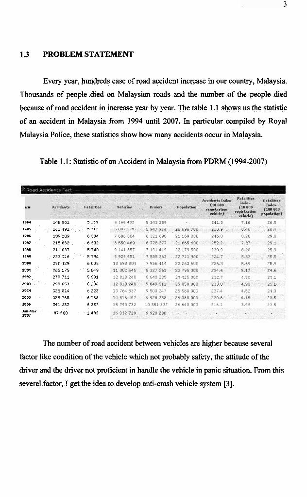
Every year, hundreds case of road accident increase in our country, Malaysia.
Thousands of people .died on Malaysian roads and the number of the people died
because of road accident in increase year by year. The table 1.1 shows us the statistic
of an accident in Malaysia fiom 1994 until 2007. In particular compiled by Royal
Malaysia Police, these statistics show how many accidents occur in Malaysia.
Table 1.1 : Statistic of an Accident in Malaysia from PDRM (1 994-2007)
ear
19Q4 148 801 5 159
14Y5 162 4 9 1 5 712
1996 189 109 6 304
1997 215 632 6 302
1998 211 037 5 740
iq99 223 116 5 794
2000 250 429 6 035
2001 265 175 5 849
?m 27" 711 5 Q O i
2083 298 653 6 286
2004 326 814 6 223
2005 328 268 6 188
2006 341 23; 6 287
Ian-Mar 2017 87 668 1 4 8 2
The number of road accident between vehicles are higher because several
factor like condition of the vehicle which not probably safety, the attitude of the
driver and the driver not proficient in handle the vehicle in panic situation. From this
several factor, I get the idea to develop anti-crash vehicle system [3].
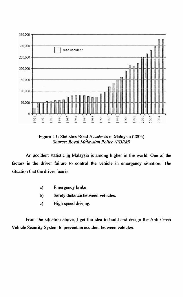
Figure 1.1 : Statistics Road Accidents in Malaysia (2005) Source: Royal Malaysian Police ( P D W
An accident statistic in Malaysia is among higher in the world. One of the
factors is the driver failure to control the vehicle in emergency situation. The
situation that the driver face is:
a) Emergency brake
b) Safety distance between vehicles,
c) High speed driving.
From the situation above, I get the idea to build and design the Anti Crash
Vehicle Security System to prevent an accident between vehicles.
1.4 SCOPE OF THE PROJECT
The scope for this project is divided into two parts which a simulation and
hardware part. Far the first part, I have made the simulation for this project to obtain
the expected result and function of the circuit system. In this part, I will use the
MULTISIM software to design and simulate the circuit and result and MATLAB
software to run the simulation of ABS application and analysis. From the simulation
part, I should be able to study and measure the signal strength af the sensor
component that will using in this project that is Ultrasonic Motion Sensor. Besides
that, I can study the function of the Antilock-Braking System (ABS) and Motor
Speed Control. From the simulation also, I can measure the approximately result that
the circuit want.
For the second part, I have to construct the hardware of anti-crash vehicle
security system prototype which consist the ultrasonic motion sensor, motor speed
controller, tachometer and antilock-braking system (ABS) by using the PROTELL
99 software. The PIC micro~controller will also construct and programmed to
integrate with software part as to make sure that the connection between both parts is
available where the input of the sensor can communicate and program to the output
application. In this project, I should be use PIC 16F88. Then, the hardware is
fabricated using printing circuit board [4].
After all the circuit has been design, selected technique will be done in order
to implement the hardware by combining idea and prototype fiom the earlier work.
The circuit that has been created must be constructing and combining it. For this
implementation, it need to do part by part means when finish one part of this project,
the test and troubleshooting can be down slowly
1.5 RESEARCH METHODOLOGY
To achieve the objectives of this project, there are four step procedure of
methodology to be use, This project consists of two parts; simulation part and
hardware part. Because of that, the methodology for this project has been divided
into two processes before I combine to complete anti-crash vehicle security system,
The following is the discussion on project methodology. The best solution for
this project is based on the figure 1.2 below. The project methodology for this project
wills involve four major phase. For the 1 st phase, Literature Review, I have gathered
the information about the project via Internet, journals, magazines, published work
and reference books and study of the software implementation (Multisim, Mikro C,
PIC-microcontroller).
For the second phase, Matlab & Multisim simulation, I have simulate the
circuit of the system for signal and distance measurement by MultisixdMatlab before
construct the hardware. I also built and simulate the anti-crash system and do the
observation and analysis the circuits,
For the third phase, Hardware development, I am using Proteus and Multisim
sohare to design the circuit and do the fabrications process on the Print Circuit
Board (PCB).
For the fourth phase, Testing Hardware, I have making a result comparison
between the fabricated circuits with the simulation.

I Literature Review I
I Writing t her is
Figure 1.2: Project Methodology in a Flowchart
CHAPTER I1
LITERATURE REVIEW
2.1 BACKGROUND STUDY
An interesting safety-related electronic system having potential for future
automotive application is the anti-collision security system. An on-board low-power
radar system can be used as a sensor for a~ electronic collision avoidance system to
provide warning of a potential with an object lying in the path of the vehicle, As
early as 1976, at least one experimental system was developed that could accurately
detect objects up to distances of about 100 yards [5 ] .
Since 1976, anti-collision security system for vehicle was develop where
radar technology and microwave sensor are combined. However, for sensing the
object or vehicle, the reflecting signal and time take between transmit and receive
signal was determine at the sensor component. The round trip time, t, fkom the
transmitter to object and back to receiver is proportional to the range, R, to the object,
as illustrated in figure 2.1 and expressed in the following equation [5 ] :
Round trip time, t = 3
In this project, the vehicle speed, V can be measure by measuring the Doppler
frequency shift of the pulse signal reflected by the ground [5]. (The Doppler
frequency shift is proportional to the speed of the moving object). This reflection can
be discriminate from the object reflectian because the ground reflection is at low
angle and short, fixed range. Ultrasonic or microwave Doppler speed sensors are
used to measure ground speed and travel distance of the vehicles, However, in latest
automotive industry, ultrasonic sensors more using because the wide range of
frequency that the sensor component can cover, In order to solve these problems and
improve the accuracy, a high-resolution ultrasonic Doppler speed sensor was
developed [5] [6].
Rrnge to Object
Radar Protected Car R - --dsiaBb
Object v
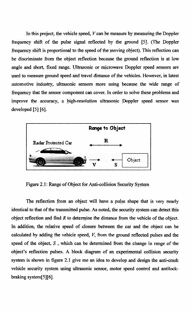
Figure 2.1 : Range of Object for Anti-collision Security System
The reflection from an object will have a pulse shape that is very nearly
identical to that of the transmitted pulse, As noted, the security system can detect this
object reflection and find R to determine the distance fiom the vehicle of the object.
In addition, the relative speed of closure between the car and the object can be
calculated by adding the vehicle speed, V, from the ground reflected pulses and the
speed of the object, S , which can be determined from the change in range of the
object's reflection pulses. A block diagram of an experimental collision security
system is shown in figure 2.1 give me an idea to develop and design the antierash
vehicle security system using ultrasonic sensor, motor speed control and antilock-
braking system[5] [6].
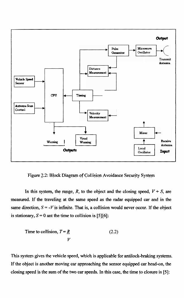
Figure 2.2: Block Diagram of Collision Avoidance Securjty System
'='v"t
Generator
Antenna
In this system, the range, R, to the object and the closing speed, V + S; are
measured. If the traveling at the same speed as the radar equipped car and in the
same direction, S = -V is infinite. That is, a collision would never occur. If the object
is stationary, S = 0 ant the time to collision is [5][6]:
Time to collision, T = R Y
e-- Timimg
Meannememt
Vehicle S p e d
This system gives the vehicle speed, which is applicable for antilock-braking systems.
If the object is another moving car approaching the sensor equipped car head-on, the
closing speed is the sum of the two car speeds. In this case, the time to closure is [5] :
1 t
wandng h i v e
Outpltr
S u w r
CPU
Antelma Scan Control
-
Time to closure, T = R
v+s
This concept of the anti-collision security system helps me in my research to
develop the project of anti-crash vehicle security system. My project exactly to
upgrade the performance of the old technology using wide-range and more accurate
sensing like using ultrasonic sensor in PIC-rnicrocontroller. It will interest to watch
this project develop and become commercially available [5][6].
2.2 ULTRASONIC SENSOR SYSTEM
Ultrasonic sensors provide precise no-touch presencelabsence sensing and
distance sensing or tracking. They are particularly useful where other sensing
technologies have difficulty, such as with clear or shiny target objects, foggy or
particle-laden air, and environments with splashing liquids. Ultrasonic solutions are
often used where larger sensors or longer sensing distances are required [7].
Ultrasonic senson work by exciting an acoustic transducer with voltage
pulses, causing the transducer to vibrate ultrasonically. These oscillations are
directed at a target and, by measuring the time for the echo to return to the transducer,
the target's distance is calculated, Ultrasonic sensors generally provide an accuracy
of 1 mm at distances ranging from 100 mm to 6,000 rnrn (over 19 feet) [7].
Target-to-sensor distance is very important in determining maximum
switching frequency. The sensor sends an ultrasonic beam through the air. It takes a
finite time for the signal to leave the sensor, travel to the target, steke the target, and
return to the s e m r as an echo. The farther a target is from the sensor, the longer it
takes the sound to complete this cycle, and the lower the switching frequency [7].
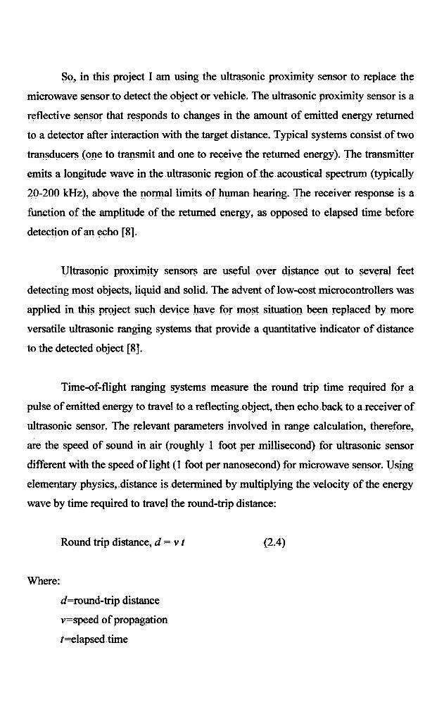
So, in this project I am using the ultrasonic proximity sensor to replace the
microwave sensor to detect the object or vehicle. The ultrasonic proximity sensor is a
reflective sensor that responds to changes in the amount of emitted energy returned
to a detector after interaction with the target distance, Typical systems consist of two
transducers (one to transmit and one to receive the returned energy). n e transmitter
emits a longitude wave in the ultrasonic region of the acoustical spectrum (typically
20-200 kHz), above the normal limits of human hearing. The receiver response is a
h t i o n of the amplitude of the returned energy, as opposed to elapsed time before
detection of an echo [8].
Ultrasonic proximity sensors are useful over distance out to several feet
detecting most objects, liquid and solid, The advent of low-cost microcontrollers was
applied in this project such device have for most situation been replaced by more
versatile ultrasonic ranging systems that provide a quantitative indicator of distance
to the detected object [8].
Time-of-flight ranging systems measure the round trip time required for a
pulse of emitted energy to travel to a reflecting object, then echo back to a receiver of
ultrasonic sensor. The relevant parameters involved in range calculation, therefore,
are the speed of sound in air (roughly 1 foot per millisecond) for ultrasonic sensor
different with the speed of light (1 foot per nanosecond) for microwave sensor. Using
elementary physics, distance is determined by multiplying the velocity of the energy
wave by time required to travel the round-trip distance:
Round trip distance, d = v t (2.4)
Where:
d=round-trip distance
v=speed of propagation
t=elapsed time
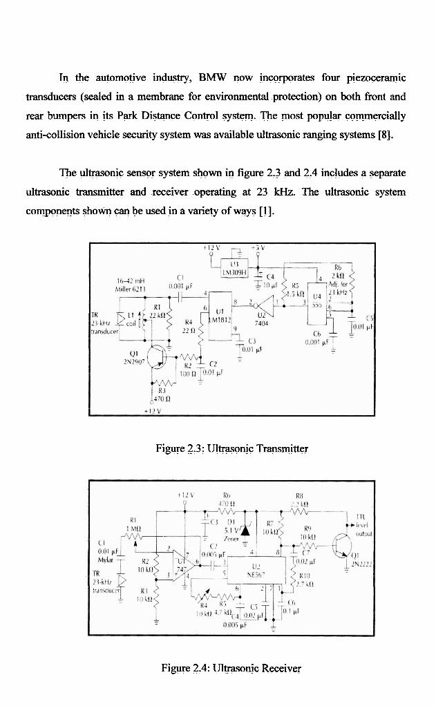
In the automotive industry, BMW now incorporates four piezogrwic
transducers (sealed in a membrane for environmental protection) on both front and
rear bumpers in its Park Distance Control system. The most popular commercially
anti-collision vehicle security system was available ultrasonic ranging systems [8],
The ultrasonic sensor system shown in figure 2.3 and 2.4 includes a separate
ultrasonic transmitter and receiver operating at 23 kHz. The ultrasonic system
components shown can be used in a variety of ways [I].
Figy-e 2.3 : Ultrasonic Transmitter
Figure 2.4: Ultraso@ Receiver

2.3 MOTOR SPEED CONTROL
The mechanical system comprises a brushed DC motor of 24 V, permanent
magnet, torque of 7.0 Nm and nominal speed of 300 rpm, Coupled to the wheel shaft,
a low resolution relative encoder (32 ppr) was used to measure motor speed, which is
part of the control system [9],
Figure 2.5: Control System Block Diagram
The pulses generated by the encoder are acquired by the PTC16FS4, an 8 bits
microcontroller with an 8 bits internal counter, 1K Flash memory and 13 I/O pins.
This microcontroller was used in the single chip configuration with a 4 MHz crystal
external circuit to generate the clock. The encoder pulses count, during a preset
period of time, is proportional to wheel speed. This is the way the encoder is used
most of the times, although in this case as the work speed is as low as 180 rpm and
the number of pulses generated in each turn, 32, is also small, a number of five or
more turns should be necessary for the speed measure, with an acceptable uncertainty.
This would make the performance of the system very slow because any correction
would only be made every five turns, A solution is a fixed number of pulses and the
setting of the time spent by these pulses so that the measured time is inversely
proportional to wheel speed. The software solves the problem of the speed being
inversely proportional to measured values [9].
2.4 ANTILOCK BRAKING SYSTEM
One of the most readily accepted applications of electronics in automobiles
has been the antilock brake system (ABS). ABS is a safety-related feature that assists
the driver in deceleration of the vehicle in poor or marginal braking conditions like
the driver failure to control the vehicle in emergency situation like emergency brake
in high speed driving. In such condition, panic braking by the driver (in non-ABS-
equipped cars) results in reduced braking effectiveness and, typically, loss of
directional control due to the tendency of the wheels to lock [5] .
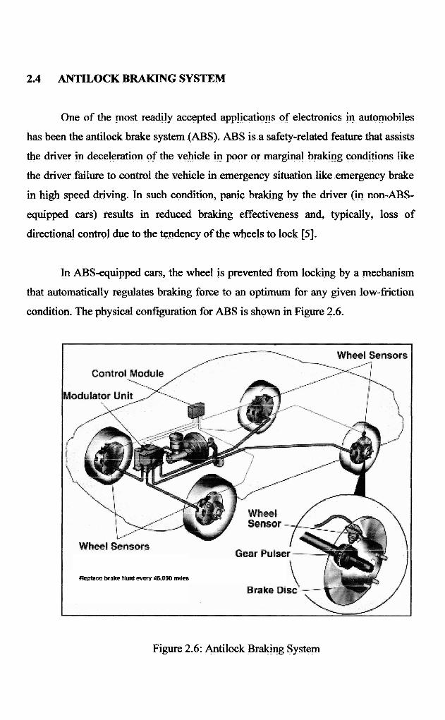
In ABS-equipped cars, the wheel is prevented from locking by a mechanism
that automatically regulates braking force to an optimum for any given low-friction
condition. The physical configuration for ABS is shown in Figure 2.6.
Replace brake tluldcvmy 4aMH) mtks
Figure 2.6: Antilock Braking System
The car is traveling at a speed U and the wheels are rotating at an angular
speed w where
w = w RPM
3 0
and where RPM is the wheel revolution per minute. When the wheel is rolling (no
applied brakes),
where R is the tire radius.
2.5 VELOCITY, POSITION, AND DISPLACEMENT
The measurement of velocity, position and displacement is essential to many
of the processes taking place during the running of the vehicle: speed control,
number of revolutions per minute of the engine, or displacement of the acceleration
and break pedals, to name some of the most typical applications [lo],
Several different technologies are used in the measurement of velocity,
position, and displacement: Eddy Current, This coil-based transducer uses the effect
of eddy currents to sense the proximity of conductive materials. The transducer and
the target establish a magnetic circuit with a nonlinear relationship between the
distance and the impedance of the transducer coil [lo].
Hall Effect. A Hall sensor is a device that, when subjected to a magnetic filed,
provides an output voltage proportional to the magnetic field strength, These devices
can be used as switches or position transducers [lo].
Variable reluctance. These sensors are electromagnetic devices consisting of
a permanent magnet surrounded by a winding of wire, The sensor is used in
conjunction with a ferrous target wheel that has either teeth or notches. When the
target wheel rotates near the sensor it changes the magnetic flux, creating a voltage
signal in the sensor coil [lo].
Reed switch. This kind of the switch consists of two parts: the reed switch
and the actuator magnet. The reed switch will change state when the actuator magnet
comes into close proximity to it [lo].
Wiegand effect. This technology employs specific magnetic properties of the
specially processed, small-diameter ferromagnetic wire, A uniform voltage pulse is
generated when the magnetic field of this wire is suddenly reversing [lo].
Magnetoresistive. This is based on the change of resistivity of a material due
to a magnetic field, The amplitude of that magnetic field depends on the relative
position between a magnet and the transducer [lo].
Potentiometric. These devices use linear or angular potentiometers whose
resistance varies linearly or angularly with length or rotation angle, They are not
used in velocity measurement [lo].
Optical sensors use light emitters and detectors together with a mask wheel in
order to measure angular rotation €1 01.
There are other sensor technologies used or available for use in automotive
applications, Same of them are restricted to classical cars based on the combustion
engines. Obstacle detection, Fardistance obstacle detection is used for avoiding
collision and for cruise control systems that control both vehicle-to-vehicle spacing
and speed. This kind of sensor is implemented using different technologies. They can
be classified in five main groups [11][12].
Milimeter-wave radar detectors are strong against rain and dirt but expensive
and have to comply with national legislation [13].
Laser or IR detectors are also comparatively inexpensive but vulnerable to
rain and dirt. Passive IR detectors are also comparatively inexpensive but vulnerable
to dirt and bad weather conditions [14].
Ultrasonic detectors have low cost and a simple structure but do not provide
good results in the detection of the medium to long distances. Machine vision
detectors have compact size and the ability to detect and classify specific objects.
The main problem is their vulnerability to rain, dirt, and night-time [I 51.
2.6 PIC MICROCONTROLLER
Microcontroller is an essential electronic device that change the electronics
design topology since its inception few decades ago. Basically, microcontroller is a
computer system that is fabricated in a single integrated chip. A microcontroller chip
consists of a central processing unit (CPU) memory modules, and several input/
output peripherals [16].
The rnicrocontroller is used as a device that can form the basis of an
embedded system for electronics applications. It provides a flexible low-cost solution
to bridge the gap between single-chip computers and the use of large numbers of
discrete logic chips [16].
Depending on various manufacturers, microcontroller is divided into several
categories (&bit, 16-bit, 32-bit). Most commonly used microcontroller is &bit
microcontroller. It is simple, small in size, and capable of doing most things related
with control and inputloutput devices [16].
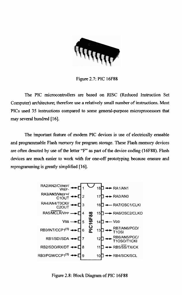
Figure 2.7: PIC 16F88
The PIC microcontrollers are based on RISC (Reduced Instruction Set
Computer) architecture; therefore use a relatively small number of instructions. Most
PICs used 35 instructions compared to some general-purpose microprocessors that
may several hundred [ 1 61.
The important feature of modern PIC devices is use of electrically erasable
and programmable Flash memory for program storage. These Flash memory devices
are often denoted by use of the letter "F" as part of the device coding (16F88). Flash
devices are much easier to work with for one-off prototyping because erasure and
reprogramming is greatly simplified [16].
RA~IAN~NREF+I ClOUT -[
vss --r-[
Figure 2.8: Block Diagram of PIC 16F88
2.7 COMPONENTS AND DEVICES
In this literature review also, the important thing that should be mentioned
earlier is to identified the components and device required for the overall circuit. The
knowledge about all the components is required to make all the connection of the
circuit more easily and accurate because the different devices have different polarity
and different characteristic.
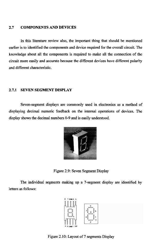
2.7.1 SEVEN SEGMENT DISPLAY
Seven-segment displays are commonly used in electronics as a method of
displaying decimal numeric feedback on the internal operations of devices. The
display shows the decimal numbers 0-9 and is easily understood.
Figure 2.9: Seven Segment Display
The individual segments making up a 7-segment display are identified by
letters as follows:
Figure 2.10: Layout of 7 segments Display
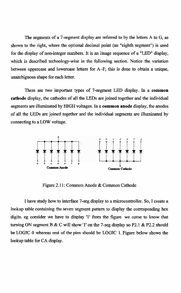
The segments of a 7-segment display are referred to by the letters A to G, as
shown to the right, where the optional decimal point (an "eighth segment") is used
for the display of non-integer numbers. It is an image sequence of a "LED" display,
which is described technology-wise in the following section. Notice the variation
between uppercase and lowercase letters for A-F; this is done to obtain a unique,
unambiguous shape for each letter.
There are two important types of 7-segment LED display. In a common
cathode display, the cathodes of all the LEDs are joined together and the individual
segments are illuminated by HIGH voltages. In a common anode display, the anodes
of all the LEDs are joined together and the individual segments are illuminated by
connecting to a LOW voltage.
a b c d s f g I Common Anode
b
Common Cathode
Figure 2.1 1 : Common Anode & Common Cathode
I have study how to interface 7-seg display to a microcontroller. So, I create a
lookup table containing the seven segment pattern to display the corresponding hex
digits. eg consider we have to display '1' from the figure we come to know that
turning ON segment B & C will show '1' on the 7-seg display so P2.1 & P2.2 should
be LOGIC 0 whereas rest of the pins should be LOGIC 1. Figure below shows the
lookup table for CA display.
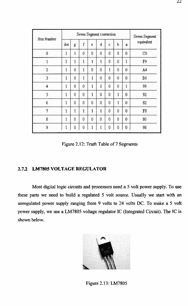
Figure 2.12: Truth Table of 7 Segments
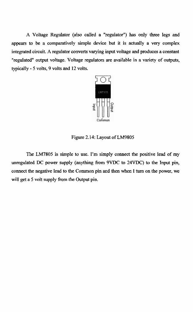
2.7.2 LM7805 VOLTAGE REGULATOR
Most digital logic circuits and processors need a 5 volt power supply. To use
these parts we need to build a regulated 5 volt source. Usually we start with an
unregulated power supply ranging &om 9 volts to 24 volts DC. To make a 5 volt
power supply, we use a LM7805 voltage regulator IC (Integrated Circuit). The IC is
shown below.
Figure 2.13: LM7805
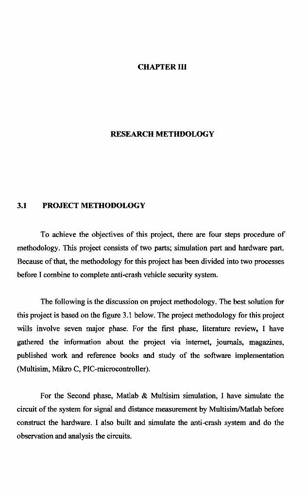
A Voltage Regulator (also called a "regulator") has only three legs and
appears to be a comparatively simple device but it is actually a very complex
integrated circuit. A regulator converts varying input voltage and produces a constant
"regulated" output voltage. Voltage regulators are available in a variety of outputs,
typically - 5 volts, 9 volts and 12 volts.
Figure 2.14: Layout of LM9805
The LM7805 is simple to use. I'm simply connect the positive lead of my
unregulated DC power supply (anything from 9VDC to 24VDC) to the Input pin,
connect the negative lead to the Common pin and then when I turn on the power, we
will get a 5 volt supply from the Output pin.
CHAPTER 111
RESEARCH METHDOLOGY
3.1 PROJECT METHODOLOGY
To achieve the objectives of this project, there are four steps procedure of
methodology. This project consists of two parts; simulation part and hardware part.
Because of that, the methodology for this project has been divided into two processes
before I combine to complete anti-crash vehicle security system.
The following is the discussion on project methodology. The best solution for
this project is based on the figure 3.1 below. The project methodology for this project
wills involve seven major phase. For the fmt phase, literature review, I have
gathered the information about the project via internet, journals, magazines,
published work and reference books and study of the software implementation
(Multisim, Mikro C, PIC-microcontrolla).
For the Second phase, Matlab & Multisim simulation, I have simulate the
circuit of the system for signal and distance measurement by Multisim/Matlab before
construct the hardware. I also built and simulate the anti-crash system and do the
observation and analysis the circuits.


