Automatic TransmissionsAutomatic Transmissionsand Transaxlesand Transaxles
CHAPTER
Automatic Transmissions and Transaxles, 6eJames D. Halderman | Tom Birch
SIXTH EDITION
Copyright © 2015 by Pearson Education, Inc.All Rights Reserved
Clutches and Bands
7
Copyright © 2015 by Pearson Education, Inc.All Rights Reserved
Automatic Transmissions and Transaxles, 6eJames D. Halderman | Tom Birch
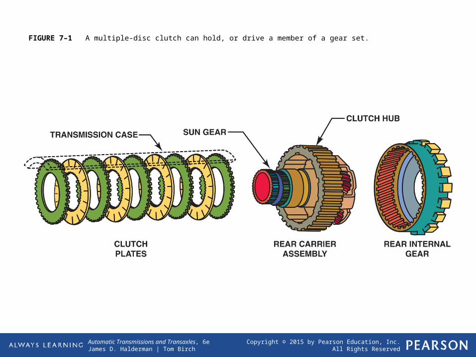
FIGURE 7–1 A multiple-disc clutch can hold, or drive a member of a gear set.
Copyright © 2015 by Pearson Education, Inc.All Rights Reserved
Automatic Transmissions and Transaxles, 6eJames D. Halderman | Tom Birch
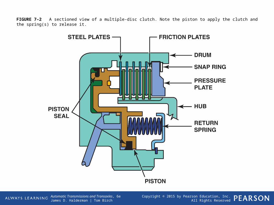
FIGURE 7–2 A sectioned view of a multiple-disc clutch. Note the piston to apply the clutch and the spring(s) to release it.
Copyright © 2015 by Pearson Education, Inc.All Rights Reserved
Automatic Transmissions and Transaxles, 6eJames D. Halderman | Tom Birch
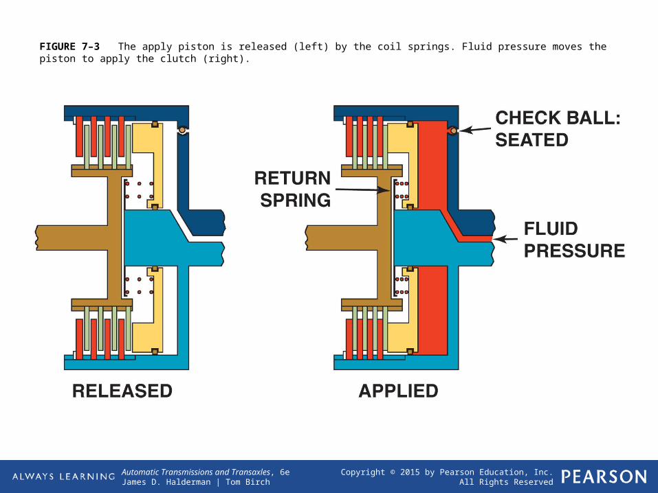
FIGURE 7–3 The apply piston is released (left) by the coil springs. Fluid pressure moves the piston to apply the clutch (right).
Copyright © 2015 by Pearson Education, Inc.All Rights Reserved
Automatic Transmissions and Transaxles, 6eJames D. Halderman | Tom Birch
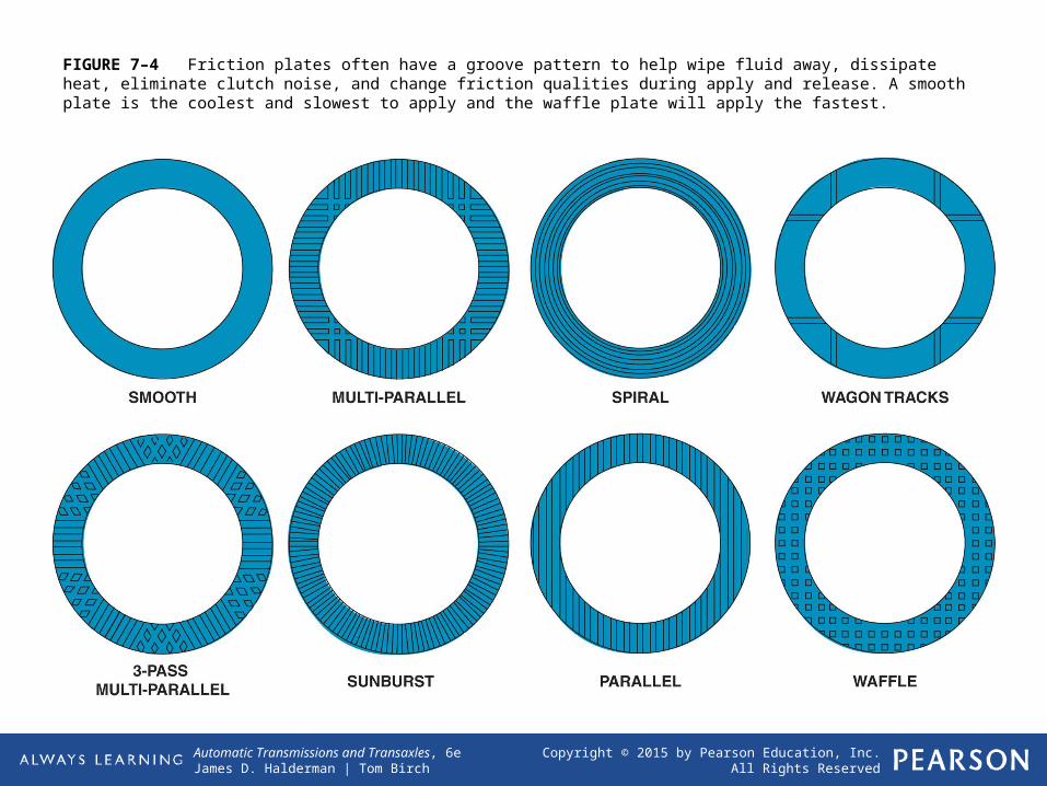
FIGURE 7–4 Friction plates often have a groove pattern to help wipe fluid away, dissipate heat, eliminate clutch noise, and change friction qualities during apply and release. A smooth plate is the coolest and slowest to apply and the waffle plate will apply the fastest.
Copyright © 2015 by Pearson Education, Inc.All Rights Reserved
Automatic Transmissions and Transaxles, 6eJames D. Halderman | Tom Birch
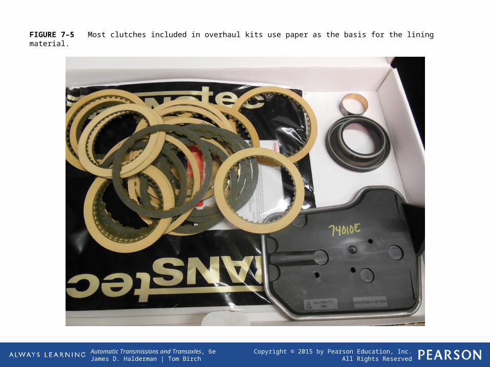
FIGURE 7–5 Most clutches included in overhaul kits use paper as the basis for the lining material.

Copyright © 2015 by Pearson Education, Inc.All Rights Reserved
Automatic Transmissions and Transaxles, 6eJames D. Halderman | Tom Birch
FIGURE 7–6 A typical clutch piston area is determined by subtracting the area of the inner diameter from the area of the outer-circle diameter.
Copyright © 2015 by Pearson Education, Inc.All Rights Reserved
Automatic Transmissions and Transaxles, 6eJames D. Halderman | Tom Birch
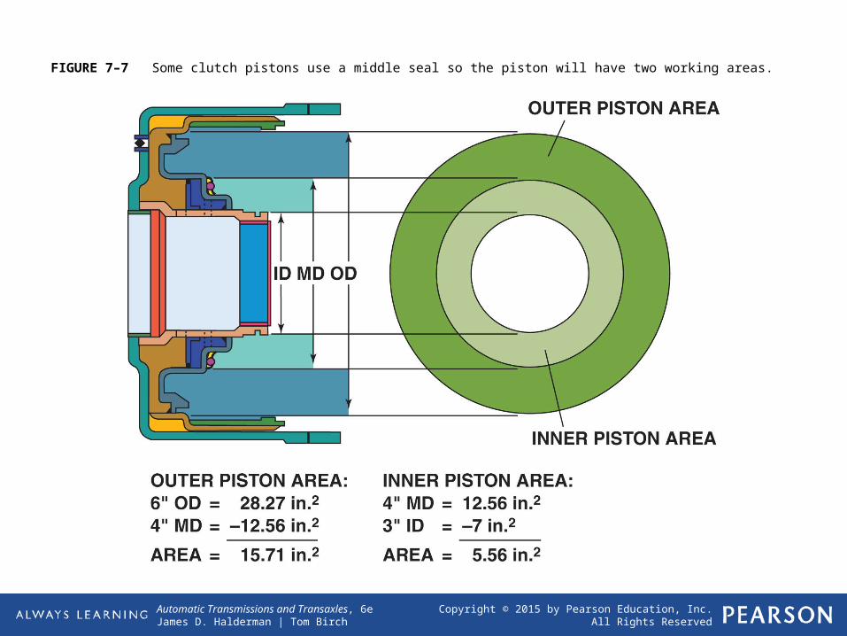
FIGURE 7–7 Some clutch pistons use a middle seal so the piston will have two working areas.
Copyright © 2015 by Pearson Education, Inc.All Rights Reserved
Automatic Transmissions and Transaxles, 6eJames D. Halderman | Tom Birch
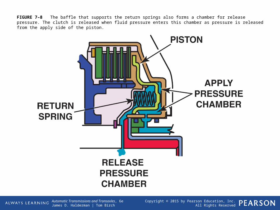
FIGURE 7–8 The baffle that supports the return springs also forms a chamber for release pressure. The clutch is released when fluid pressure enters this chamber as pressure is released from the apply side of the piston.
Copyright © 2015 by Pearson Education, Inc.All Rights Reserved
Automatic Transmissions and Transaxles, 6eJames D. Halderman | Tom Birch
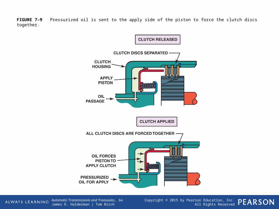
FIGURE 7–9 Pressurized oil is sent to the apply side of the piston to force the clutch discs together.
Copyright © 2015 by Pearson Education, Inc.All Rights Reserved
Automatic Transmissions and Transaxles, 6eJames D. Halderman | Tom Birch
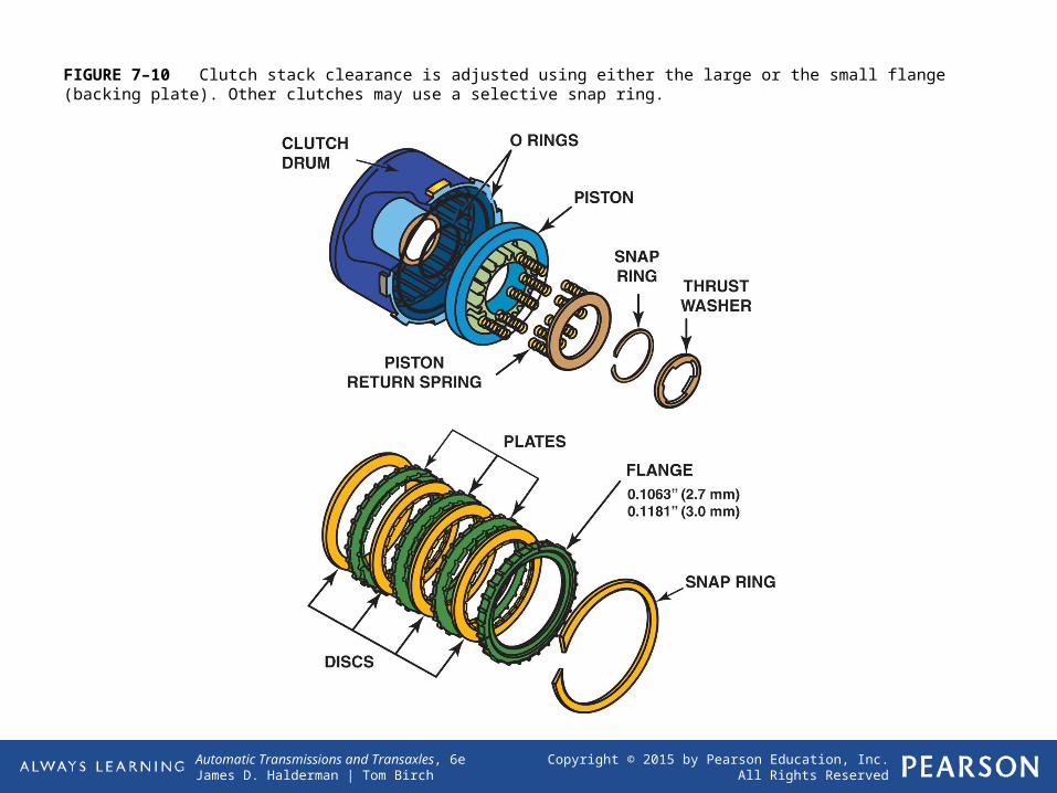
FIGURE 7–10 Clutch stack clearance is adjusted using either the large or the small flange (backing plate). Other clutches may use a selective snap ring.
Copyright © 2015 by Pearson Education, Inc.All Rights Reserved
Automatic Transmissions and Transaxles, 6eJames D. Halderman | Tom Birch
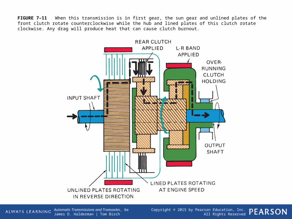
FIGURE 7–11 When this transmission is in first gear, the sun gear and unlined plates of the front clutch rotate counterclockwise while the hub and lined plates of this clutch rotate clockwise. Any drag will produce heat that can cause clutch burnout.
Copyright © 2015 by Pearson Education, Inc.All Rights Reserved
Automatic Transmissions and Transaxles, 6eJames D. Halderman | Tom Birch
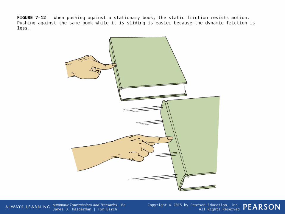
FIGURE 7–12 When pushing against a stationary book, the static friction resists motion. Pushing against the same book while it is sliding is easier because the dynamic friction is less.

Copyright © 2015 by Pearson Education, Inc.All Rights Reserved
Automatic Transmissions and Transaxles, 6eJames D. Halderman | Tom Birch
Frequently Asked QuestionWhat Is Wet Friction?
Wet friction occurs because ATF fills the space between the clutch plates. This ATF film transmits torque between the clutch plates as the clutch is
being applied. The action of the film of fluid is called fluid shear.
As the clutch is applied, the clutch plate clearance is reduced as the fluid is squeezed from between the
plates, leaving a film of fluid. This hydrodynamic film begins transferring torque. Fluid shear, which is the
resistance to motion, is the primary torque transmitting force at the start of a shift. As the plate clearance is reduced, fluid viscosity increases and its
resistance to shear increases. The clutch plates make physical contact at the end of application.
Since there is no movement between the plates at this time, friction lining wear is minimized.
Copyright © 2015 by Pearson Education, Inc.All Rights Reserved
Automatic Transmissions and Transaxles, 6eJames D. Halderman | Tom Birch
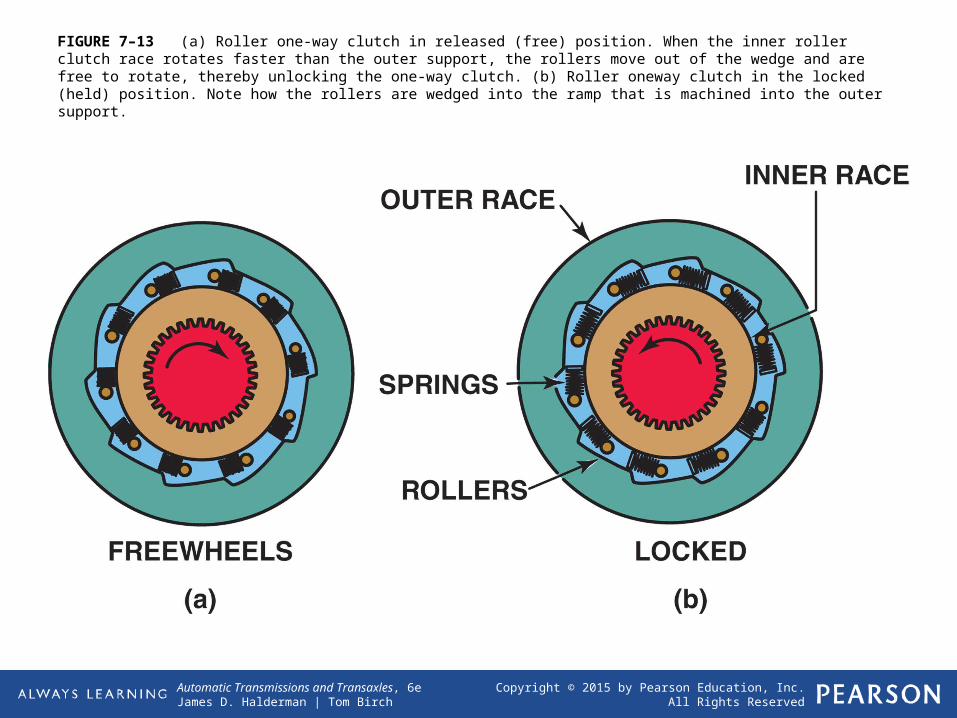
FIGURE 7–13 (a) Roller one-way clutch in released (free) position. When the inner roller clutch race rotates faster than the outer support, the rollers move out of the wedge and are free to rotate, thereby unlocking the one-way clutch. (b) Roller oneway clutch in the locked (held) position. Note how the rollers are wedged into the ramp that is machined into the outer support.
Copyright © 2015 by Pearson Education, Inc.All Rights Reserved
Automatic Transmissions and Transaxles, 6eJames D. Halderman | Tom Birch
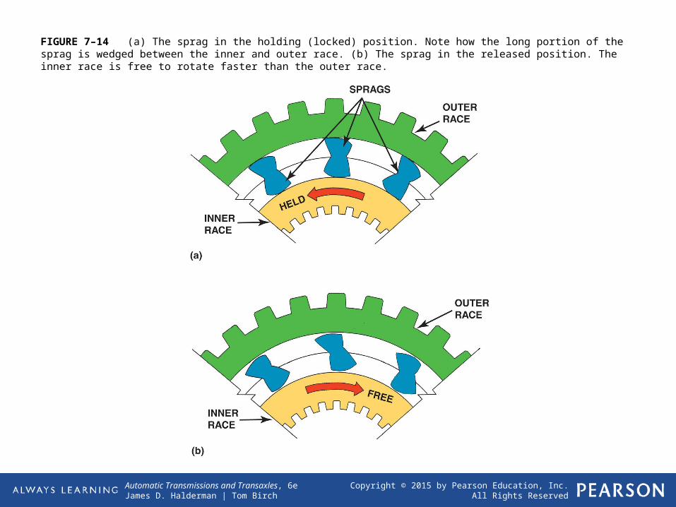
FIGURE 7–14 (a) The sprag in the holding (locked) position. Note how the long portion of the sprag is wedged between the inner and outer race. (b) The sprag in the released position. The inner race is free to rotate faster than the outer race.
Copyright © 2015 by Pearson Education, Inc.All Rights Reserved
Automatic Transmissions and Transaxles, 6eJames D. Halderman | Tom Birch
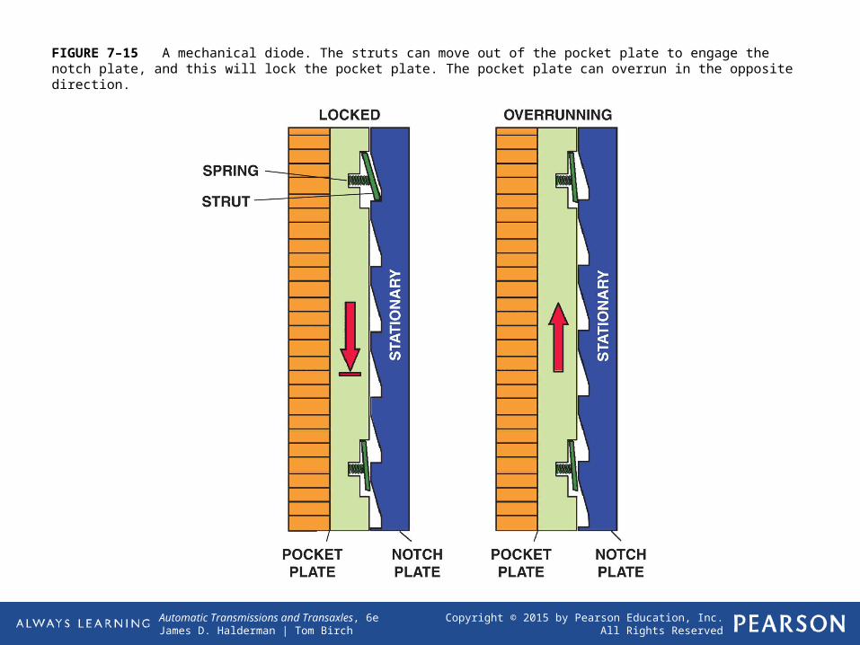
FIGURE 7–15 A mechanical diode. The struts can move out of the pocket plate to engage the notch plate, and this will lock the pocket plate. The pocket plate can overrun in the opposite direction.

Copyright © 2015 by Pearson Education, Inc.All Rights Reserved
Automatic Transmissions and Transaxles, 6eJames D. Halderman | Tom Birch
FIGURE 7–16 This clutch hub and sprag clutch should rotate freely in a counterclockwise direction but should lock up in the opposite direction.
Copyright © 2015 by Pearson Education, Inc.All Rights Reserved
Automatic Transmissions and Transaxles, 6eJames D. Halderman | Tom Birch
Frequently Asked QuestionWhat Is a Clutch-to-Clutch Type Transmission?
A clutch-to-clutch transmission or transaxle is a unit that does not use one-way clutches and instead just
uses multiple-plate clutches for all clamping functions. A Chrysler 41TE transaxle is an example of
a clutch-to-clutch automatic transmission. The primary reason for not using one-way clutches is that
the metal particles that are detached from these assemblies are attracted to the magnetic solenoids. These particles can clog the screens and reduce the flow of fluid through the solenoid valves. This leads to many types of transmission or transaxle failures that are prevented by not using steel-on-steel units
such as roller clutches or mechanical diodes.
Copyright © 2015 by Pearson Education, Inc.All Rights Reserved
Automatic Transmissions and Transaxles, 6eJames D. Halderman | Tom Birch
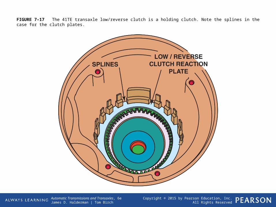
FIGURE 7–17 The 41TE transaxle low/reverse clutch is a holding clutch. Note the splines in the case for the clutch plates.
Copyright © 2015 by Pearson Education, Inc.All Rights Reserved
Automatic Transmissions and Transaxles, 6eJames D. Halderman | Tom Birch
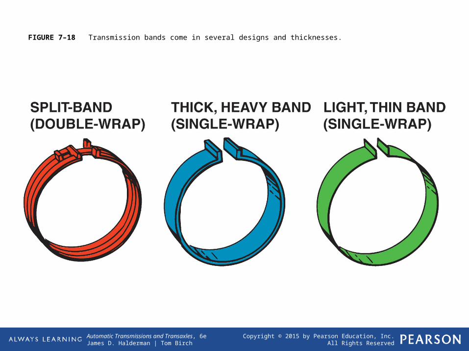
FIGURE 7–18 Transmission bands come in several designs and thicknesses.
Copyright © 2015 by Pearson Education, Inc.All Rights Reserved
Automatic Transmissions and Transaxles, 6eJames D. Halderman | Tom Birch
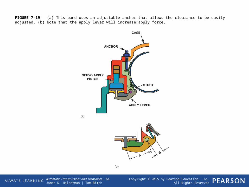
FIGURE 7–19 (a) This band uses an adjustable anchor that allows the clearance to be easily adjusted. (b) Note that the apply lever will increase apply force.
Copyright © 2015 by Pearson Education, Inc.All Rights Reserved
Automatic Transmissions and Transaxles, 6eJames D. Halderman | Tom Birch
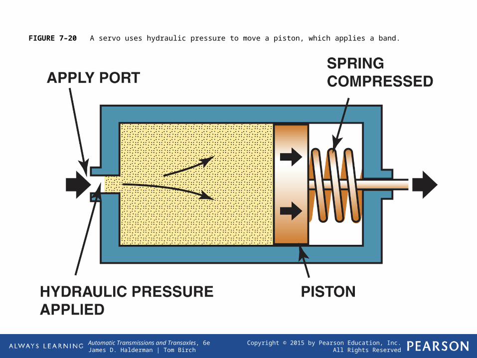
FIGURE 7–20 A servo uses hydraulic pressure to move a piston, which applies a band.
Copyright © 2015 by Pearson Education, Inc.All Rights Reserved
Automatic Transmissions and Transaxles, 6eJames D. Halderman | Tom Birch
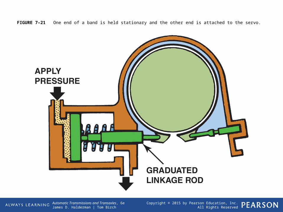
FIGURE 7–21 One end of a band is held stationary and the other end is attached to the servo.
Copyright © 2015 by Pearson Education, Inc.All Rights Reserved
Automatic Transmissions and Transaxles, 6eJames D. Halderman | Tom Birch
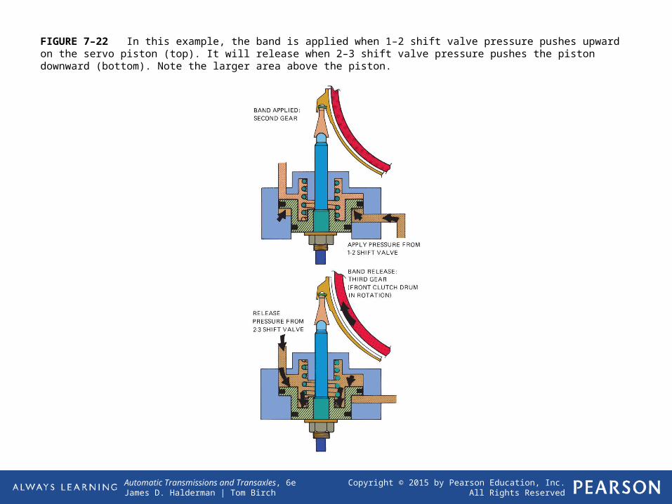
FIGURE 7–22 In this example, the band is applied when 1–2 shift valve pressure pushes upward on the servo piston (top). It will release when 2–3 shift valve pressure pushes the piston downward (bottom). Note the larger area above the piston.
Copyright © 2015 by Pearson Education, Inc.All Rights Reserved
Automatic Transmissions and Transaxles, 6eJames D. Halderman | Tom Birch
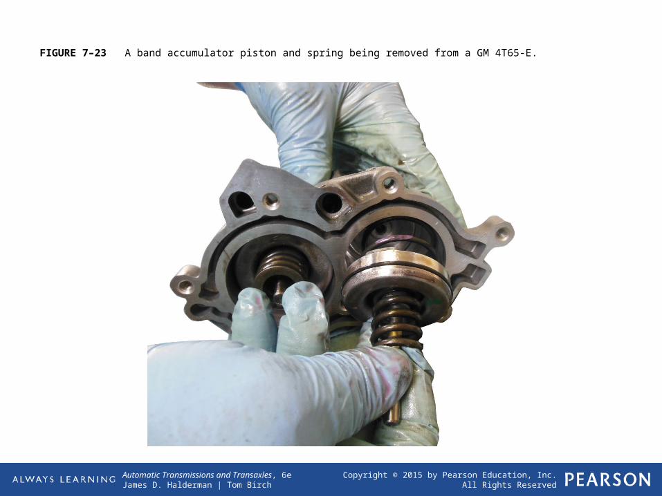
FIGURE 7–23 A band accumulator piston and spring being removed from a GM 4T65-E.
Copyright © 2015 by Pearson Education, Inc.All Rights Reserved
Automatic Transmissions and Transaxles, 6eJames D. Halderman | Tom Birch
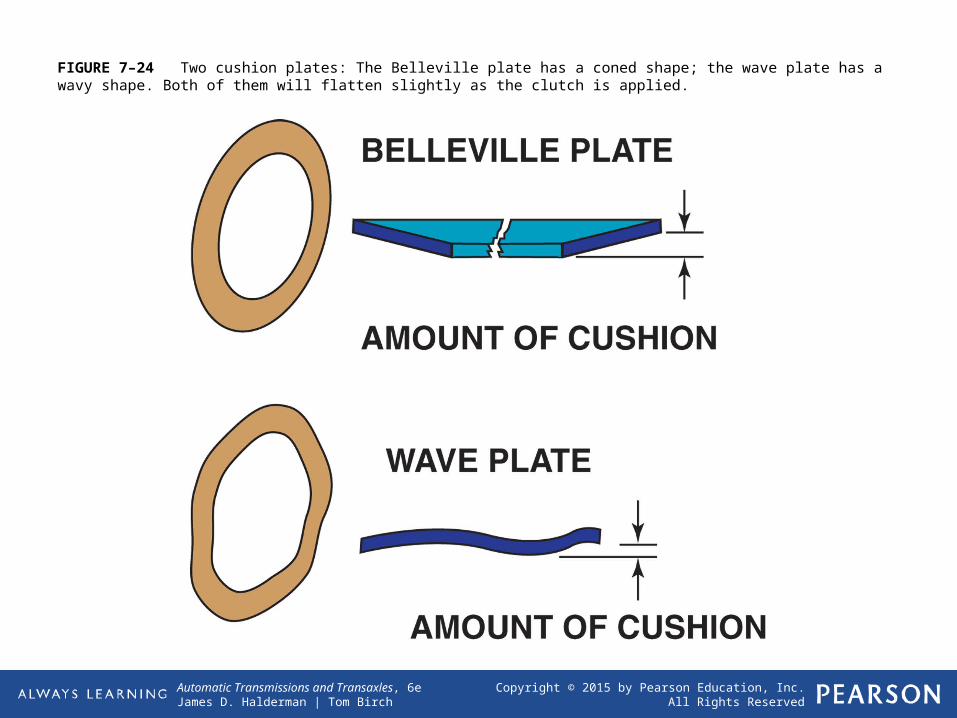
FIGURE 7–24 Two cushion plates: The Belleville plate has a coned shape; the wave plate has a wavy shape. Both of them will flatten slightly as the clutch is applied.


