
11
ApplicAtion note
Copyright © 2012-2016 Cree, Inc. All rights reserved. The information in this document is subject to change without notice. Cree® and XLamp® are registered trademarks and the Cree logo is a trademark of Cree, Inc. This document is provided for informational purposes only and is not a warranty or a specification. For product specifications, please see the data sheets available at www.cree.com. For warranty information, please contact Cree Sales at [email protected].
Cree, Inc.4600 Silicon Drive
Durham, NC 27703USA Tel: +1.919.313.5300
ww
w.C
ree.
Co
m/X
LAm
pC
LD-A
P118 R
ev 0C
Avoidance of Ceramic-Substrate-Based LED Chip Cracking Induced by PCB Bending or Flexing
IntroDuCtIon
Printed circuit board (PCB) bending and/or flexing is an
unavoidable phenomenon that is known to exist and is easily
encountered during electronic board assembly processes. PCB
bending and/or flexing is the fundamental source of tensile
stress induced on the electronic components on the board
assembly. For more brittle components, like ceramic-based
electronic components, micro-cracks can be induced, which
can eventually lead to a fatal failure of the components. For this
reason, many standards organizations throughout the world
specify the methods under which electronic board assemblies
must be tested to ensure their robustness, sometimes as a pre-
condition to more rigorous environmental tests such as thermal
cycling or thermal shock.
This application note discusses the trends and symptoms
observed from failed ceramic-substrate-based LED components
in LED luminaires. Cree’s testing and analysis of such luminaires
revealed LEDs that exhibited one or more cracks in the LED
chip as well as in the ceramic substrate. It is not the intent of
this application note to identify and quantify all the conditions
that induce cracks in an LED chip and the underlying ceramic
tABLE oF ContEntS
Introduction ..................................................................................1
LED luminaire assembly ..............................................................2
What can cause PCB bending/flexing? ......................................4
Trends observed from LED chip cracks induced by PCB
bending/flexing ............................................................................5
Summary ......................................................................................7
References ....................................................................................8
LED chip crack (highlighted in blue) due to PCB bending/flexing
22
Copyright © 2012-2016 Cree, Inc. All rights reserved. The information in this document is subject to change without notice. Cree® and XLamp® are registered trademarks and the Cree logo is a trademark of Cree, Inc. This document is provided for informational purposes only and is not a warranty or a specification. For product specifications, please see the data sheets available at www.cree.com. For warranty information, please contact Cree Sales at [email protected].
2
AvoidAnce of cerAmic-SubStrAte-bASed Led chip crAcking induced by pcb bending or fLexing
substrate, but to explain some prevalent causes of PCB bending and flexing resulting in cracks and to suggest some actions to minimize
their occurrence.
The Multi-Layer Ceramic Chip (MLCC) capacitor industry has heavily investigated component cracks caused by PCB bending/flexing.
When a populated circuit board is bent, a significant amount of tension is directed to the ceramic capacitor through the solder joints as
the board forms an arc. Ceramic material is inherently hard and brittle, with no elasticity, so any stress induced by bending the PCB is
directly transmitted to the body of the ceramic-based electronic components. Since this stress must be released somehow, cracks can
result on the ceramic-based electronic components. Immediate detection of cracks and/or failures in the affected components may not
be possible because the characteristics and/or symptoms may not manifest as a fatal or catastrophic failure. With continued operation
of the component and exposure to humidity in the environment, further degradation of the crack(s) occurs, eventually leading to a fatal/
catastrophic failure of the affected component.
Such phenomena have also been observed in LED board assemblies that are populated with ceramic-substrate-based LED components.
LED luminaire manufacturers have encountered a failure mode that is typically reported as “no light output”, “dimmed light output” or
“flickering light output.” When such samples were analyzed, a crack in the LED chip in-line with a ceramic-substrate crack was typically
observed.
LED LumInAIrE ASSEmBLy
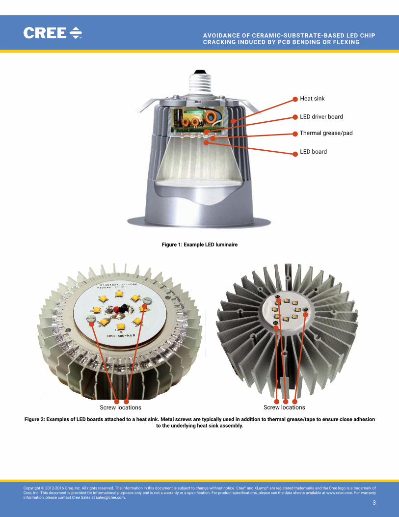
In a typical LED luminaire, the LED board is secured to the aluminum heat sink/housing using one or more metal screws. Thermal grease
or a thermal pad is typically applied between the LED board and the aluminum heat sink to help with thermal conduction during luminaire
operation. An electronic driver circuit may be included either internal or external to the luminaire depending on the size and design
constraints of the luminaire. Figure 1 shows an example of a typical LED luminaire. Figure 2 shows LED boards secured to the underlying
heat sink assembly with screws.
33
Copyright © 2012-2016 Cree, Inc. All rights reserved. The information in this document is subject to change without notice. Cree® and XLamp® are registered trademarks and the Cree logo is a trademark of Cree, Inc. This document is provided for informational purposes only and is not a warranty or a specification. For product specifications, please see the data sheets available at www.cree.com. For warranty information, please contact Cree Sales at [email protected].
3
AvoidAnce of cerAmic-SubStrAte-bASed Led chip crAcking induced by pcb bending or fLexing
Figure 1: Example LED luminaire
Figure 2: Examples of LED boards attached to a heat sink. metal screws are typically used in addition to thermal grease/tape to ensure close adhesion to the underlying heat sink assembly.
Heat sink
Thermal grease/pad
LeD board
LeD driver board
Screw locationsScrew locations

44
Copyright © 2012-2016 Cree, Inc. All rights reserved. The information in this document is subject to change without notice. Cree® and XLamp® are registered trademarks and the Cree logo is a trademark of Cree, Inc. This document is provided for informational purposes only and is not a warranty or a specification. For product specifications, please see the data sheets available at www.cree.com. For warranty information, please contact Cree Sales at [email protected].
4
AvoidAnce of cerAmic-SubStrAte-bASed Led chip crAcking induced by pcb bending or fLexing
WhAt CAn CAuSE PCB BEnDIng/FLExIng?
Following are situations in which a PCB can bend or flex, resulting in cracks in an LED chip attached to it.
1. Screw tightening/torquing
Manual tightening or automated torquing of metal screws is typically used to attach an LED board to the heat sink assembly during
LED luminaire manufacturing. PCB flexing, which occurs due to the board’s natural characteristic to form an arc when it is deflected,
can easily occur during this process, inducing stress directly on the ceramic-substrate-based LEDs soldered on the PCB. This force is
transmitted through the solder to the ceramic substrate and to the eutectically attached LED chip. Figure 3 is a pictorial representation of
the directions of stress applied to an LED during PCB bending/flexing.
Figure 3: Direction of stress forces applied to LED when PCB is bent/flexed
2. uneven/convex PCB surface
PCB flexing can be amplified if the surface to which the LED board is being attached is uneven, warped or convex. This can easily occur
during manual application of thermal grease if the amount dispensed is not controlled or if it is applied unevenly. Applying a layer of
thermal tape or thermal grease only under the LED may be sufficient to conduct heat away from the LED chip during its operation,
however this creates an undesirable convex or uneven surface to which the LED board is attached, which in turn causes PCB bending/
flexing during the screw tightening process, exerting stress on the LED. Even if it covers the entire surface of the board, a thick thermal
tape layer under the LED board is also not necessarily the best solution when it comes to preventing board flexing. Same as the partial/
uneven surface effect, overtightening the screws can occur due to the resilience of the thermal tape material. This, in turn, causes PCB
bending/flexing to occur.
3. Reflow soldering the LED board
PCB warping or bending can occur during the LED board assembly reflow soldering process, especially if materials of greatly different
coefficient of thermal expansion (CTE) make up the PCB. Stress can be applied to the LED during this process by the volume of solder
used to attach it to the underlying PCB surface. Using an excessive amount of solder can lead to greater susceptibility to thermal stress,
resulting in cracks at the solder joint as the LED gets hot.
4. PCB punching/separation
For manufacturing efficiency, LED board assembly manufacturers typically populate multiple LED boards at once with the boards tied
together. After the reflow and/or test process, a punching tool or a manual breaking process is then used to separate the LED boards.
During this separation process, PCB bending/flexing can easily occur, exerting excessive stress on the ceramic-substrate-based LEDs
that are soldered onto it, causing a crack.
Fig 3. direction of the stress applied to the LED component when the PCB is bent
55
Copyright © 2012-2016 Cree, Inc. All rights reserved. The information in this document is subject to change without notice. Cree® and XLamp® are registered trademarks and the Cree logo is a trademark of Cree, Inc. This document is provided for informational purposes only and is not a warranty or a specification. For product specifications, please see the data sheets available at www.cree.com. For warranty information, please contact Cree Sales at [email protected].
5
AvoidAnce of cerAmic-SubStrAte-bASed Led chip crAcking induced by pcb bending or fLexing
Operator mishandling of the LED board assembly during this process is another area that should not be overlooked when investigating a
root cause of LED component failure related to board bending/flexing.
trEnDS oBSErvED From LED ChIP CrACkS InDuCED By PCB BEnDIng/FLExIng
Cree’s analysis of failed LED luminaires revealed the following trends.
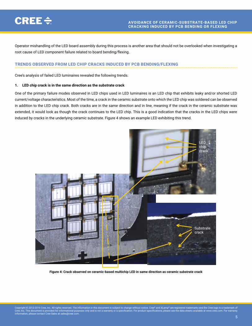
1. LED chip crack is in the same direction as the substrate crack
One of the primary failure modes observed in LED chips used in LED luminaires is an LED chip that exhibits leaky and/or shorted LED
current/voltage characteristics. Most of the time, a crack in the ceramic substrate onto which the LED chip was soldered can be observed
in addition to the LED chip crack. Both cracks are in the same direction and in line, meaning if the crack in the ceramic substrate was
extended, it would look as though the crack continues to the LED chip. This is a good indication that the cracks in the LED chips were
induced by cracks in the underlying ceramic substrate. Figure 4 shows an example LED exhibiting this trend.
Figure 4: Crack observed on ceramic-based multichip LED in same direction as ceramic substrate crack
Substrate crack
LED chip crack
Fig 4. LED chip crack in line with substrate crack
LeD chip crack
Substrate crack

66
Copyright © 2012-2016 Cree, Inc. All rights reserved. The information in this document is subject to change without notice. Cree® and XLamp® are registered trademarks and the Cree logo is a trademark of Cree, Inc. This document is provided for informational purposes only and is not a warranty or a specification. For product specifications, please see the data sheets available at www.cree.com. For warranty information, please contact Cree Sales at [email protected].
6
AvoidAnce of cerAmic-SubStrAte-bASed Led chip crAcking induced by pcb bending or fLexing
2. Cracks in the LED chip and/or ceramic substrate perpendicular to PCB bending/flexing direction
Another trend observed from the LED chip cracks was that, for assemblies that used an even number of screws, the direction of the
cracks was always perpendicular to the axis of the screw locations. Figure 5 shows a damaged LED chip that was removed from an LED
luminaire. The LED board was attached with two screws.
Figure 5: LED crack perpendicular to the stress direction. Image on the right is a close-up view of the PCB on the left.
3. Cracks in the LED chip in the shape of an arc
If an odd number of screws was used to attach the PCB, the cracks observed on the LED chip were in the shape of an arc in the direction
opposite the board bending direction. Figure 6 shows a damaged LED chip that was on a PCB attached with three screws.
Actual chip & substrate crack direction
Expected chip crack direction
Board bending direction Screw hole
Screw hole
Fig 5B. LED crack in direction perpendicular to the stress.
Screw hole
Screw hole
Board bending direction
Expected chip crack direction
Actual chip & substrate crack direction
Expected chip crack direction
Board bending direction Screw hole
Screw hole
Fig 5B. LED crack in direction perpendicular to the stress.
LED chip & substrate crack
Actual chip & substrate crack direction

77
Copyright © 2012-2016 Cree, Inc. All rights reserved. The information in this document is subject to change without notice. Cree® and XLamp® are registered trademarks and the Cree logo is a trademark of Cree, Inc. This document is provided for informational purposes only and is not a warranty or a specification. For product specifications, please see the data sheets available at www.cree.com. For warranty information, please contact Cree Sales at [email protected].
7
AvoidAnce of cerAmic-SubStrAte-bASed Led chip crAcking induced by pcb bending or fLexing
Figure 6: LED chip crack in an arc shape. Images on the right are close-up views of the LED lamp on the left.
SummAry
Cree has identified cracks in the LED chip and substrate as the root cause of the unstable, partial or no emission failures observed from
ceramic-substrate-based LEDs that were used in LED luminaires. This failure mode was more predominantly observed in MR16- or GU10-
type fixtures. All LED luminaire manufacturers who experienced this failure mode used one or more metal screws in addition to thermal
grease or tape to fasten a PCB populated with one or more ceramic-substrate-based LEDs to a heat sink housing. The metal screws were
fastened or tightened either manually using a hand-held screwdriver or by an automated process using a known torque force.
Cree’s analysis results observed from failed LEDs indicated PCB bending/flexing is the most likely root cause of LED component failure
and some trends observed are worth noting. They are:
1. Cracked LED chip damage is seen only on ceramic-substrate-based LEDs. Metal-frame-based LEDs do not exhibit PCB flexing
induced cracks.
2. Cracks in the LED chip are always in line with cracks in the ceramic substrate, if present.
3. If an even number of screws is used to fasten the LED board to the heat sink assembly, the direction of the crack on the LED chip and/
or ceramic substrate is always perpendicular to the PCB bending/flexing direction.
4. If an odd number of screws is used to fasten the LED board to the heat sink assembly, the crack on the LED chip is in the shape of
an arc.
Ceramic substrate crack
LED chip crack
Screw locations
Fig 5C. LED chip crack in arc shape
Screw locations
Ceramic substrate crack
LED chip crack
88
Copyright © 2012-2016 Cree, Inc. All rights reserved. The information in this document is subject to change without notice. Cree® and XLamp® are registered trademarks and the Cree logo is a trademark of Cree, Inc. This document is provided for informational purposes only and is not a warranty or a specification. For product specifications, please see the data sheets available at www.cree.com. For warranty information, please contact Cree Sales at [email protected].
8
AvoidAnce of cerAmic-SubStrAte-bASed Led chip crAcking induced by pcb bending or fLexing
5. The larger the LED component, whether in single- or multi-chip form, the more susceptible it is to crack damage.
PCB bending/flexing is an unavoidable phenomenon that exists in the electronic board assembly industry, including LED boards. This PCB
bending/flexing that can cause cracks in the LED chip which in turn cause a catastrophic failure in the LED component can be minimized
if the following cautions are practiced.
1. Do not overtighten the screws when attaching an LED board to a heat sink.
2. Always use automated torquing and tightening of the screws with set torque force.
3. Do not use an excessive amount of thermal grease or a thick thermal tape/pad.
4. Do not manually apply thermal grease; use a controlled-volume dispensing method.
5. Do not use partial application of thermal grease or tape, i.e., application under the LED component only. An even spread and controlled
volume are critical to minimize possible board bending/flexing during the fastening process.
6. Do not mount an LED board on a warped, convex, or uneven surface.
7. Do not use an excessive amount of solder to attach an LED to a PCB.
8. When designing an LED board, consider using materials close in CTE to minimize CTE mismatch during thermal exposure.
9. When handling LED boards after assembly, always ensure that the boards are properly supported to minimize board bending/flexing.
10. If LED boards must be separated after assembly, ensure that the boards to be separated are firmly supported in a fixture that prevents
them from being flexed or bent.
11. When designing an LED board, ensure that the size and weight of the LEDs are evenly distributed on the board to prevent possible
bending/flexing during thermal exposure.
Further investigation of PCB bending/flexing induced failures to determine specific, quantified steps to minimize this occurrence in their
luminaires is left to luminaire manufacturers.
rEFErEnCES
1. KEMET Engineering Bulletin F-2111, Ceramic Chip Capacitors “Flex Cracks” Understanding & Solutions, January, 1998. Jim Bergenthal
2. KEMET Engineering Bulletin F-2110, Capacitance Monitoring While Flex Testing, June, 1995. Jim Bergenthal and John D. Prymak
3. Safer Technology, Ltd., Application Note AN0005, Mechanical Cracking, The Major Cause for Multilayer Ceramic Capacitor Failures


