
BALANCES
Balance of a distillation unit
10 kmol of a feed containing 55 mol. % of a component A and 45 mol. % of B was processed in a
distillation unit. 5 kmol of distillate with composition of 90 mol. % of A was obtained. What are the
amount and composition of the bottom product?
Solution: 1. Schematics of the distillation unit.
Matrix of the problem: a simple table in which columns contain data concerning each stream, the first
row total number of moles for each stream and the rest composition expressed in molar fractions. The
table will be 3 x 3 for this problem.
1 2 3
n / kmol 10 5 n3
A 0.55 0.9 xA,3
B 0.45 0.1 xB,3
We can easily see from the table that the number of unknowns is 3. To solve the problem, we need to
write down three independent equations. These equations will be: 2 mass balances and the condition
that the sum over molar fractions in each stream is equal to one.
10 = 5 + 𝑛3
10 ∙ 0.5 = 0.9 ∙ 5 + 𝑥𝐴,3𝑛3
1 = 𝑥𝐴,3 + 𝑥𝐵,3
This set of equations can easily be solved yielding the following results: n3 = 5 kmol, xA,3 = 0.2, and
xB,3=0.8.
3 – bottom product
2 - distillate
1 - feed

Balance of the preparation of a mixture with a given composition
300 kg of a mixture containing 10 wt. % of a component A, 10 wt. % of B and 80wt % of C is in a storage
tank. The goal is to obtain 500 kg of a mixture with the composition of 20 wt. % of A, and 30 wt. % of B.
The following is available: a mixture AB containing 90 wt.% of A and 10 wt. % of B, A mixture of BC
containing 8 wt. % of B and 92 wt. % of C, and pure component B. What amounts of mixtures AB and BC
and pure component B have to be added to the original mixture?
Solution: Schematics of the problem.
Matrix of the problem:
1 2 3 4 5
m /kg m1 m2 m3 300 500
wA 0.9 0 0 0.1 0.2
wB 0.1 0.08 1 0.1 0.3
wC 0 0.92 0 0.8 0.5
The number of unknowns is three, i. e. we need three independent equations to solve this problem. The
three independent equations are mass balances:
1. total balance: 𝑚1 + 𝑚2 + 𝑚3 + 300 = 500
2. balance of comp. A: 0.9𝑚1 + 300 ∙ 0.1 = 500 ∙ 0.2
3. balance of comp. C: 0.92𝑚2 + 300 ∙ 0.8 = 500 ∙ 0.5
This set of equations can easily be solved yielding the following results: m1 = 77.78 kg, m2 = 10.87 kg, m3 = 111.35 kg.
5 – final mixture
3 – pure B
4 – original mixture
2 – mixture BC
1 – mixture AB

FLUID TRASPORT
Input power of a pump and energy consumption.
Water is pumped from an open well into a closed reservoir where a constant overpressure of 0.02 MPa is
kept. The height difference in water levels in the well and the reservoir is 25 m, the cross-sections of the
well and the reservoir are essentially identical. Water flows through a plastic pipe with a mean velocity
of 1 ms-1 and its temperature is 10 DC (= 1000 kg m-3, = 1.3×10⁻³ Pa s). The tubing is 28 m long, its
inner diameter is 32 mm, and contains fittings (saci kos, uzaviraci ventil, kolena 90 s.) Calculate he input
power of a pump shaft, input power of the electromotor and a daily energy consumption if the total
efficiency of pumping is 60 % and the efficiency of electromotor is 74 %.
Data: Density of water = 1000 kg m-3; dynamic viscosity of water = 1.3×10⁻³ Pa s; pressure in the well
p1 = pATM = 101325 Pa; pressure in the reservoir p2 = pATM + 20000; inner diameter of the pipe d = 0.032 m;
the length of the pipe L = 28 m; mean velocity of the water: v = 1.2 ms-1; pumping height difference h =
25 m; efficiency of the pump c = 0.6; efficiency of the electromotor el = 0.74.
Solution:
We will use Bernoulli equation with a term corresponding to the energy supplied by the pump. This
equation reads: 𝑝1
𝜌+
𝑣12
2+ 𝑔𝑧1 + 𝑒𝑐 =
𝑝2
𝜌+
𝑣22
2+ 𝑔𝑧2 + 𝑒𝑑𝑖𝑠. One can rearrange the equation to arrive at
the expression for the ec. 𝑒𝑐 =𝑝2−𝑝1
𝜌+
𝑣22−𝑣1
2
2+ 𝑔(𝑧2 − 𝑧1) + 𝑒𝑑𝑖𝑠. In this equation, the second term ofn
the right side equals zero (v1= v2= v), the third term on the right side equals to hg, and edis can be
calculated from 𝑒𝑑𝑖𝑠 = (𝜆𝐿
𝑑
𝑣2
2) + (∑ 𝜁𝑗)
𝑣2
2, where the first term corresponds to the energy loss in a
plastic pipe and the second on all fittings.
a) calculation of the second term in edis: the coefficient equals to 6 for suction basket, 3 for
closing ventl and 2 x 1.26 for the two 90° elbow-pipes which gives ∑ 𝜁𝑗 = 12.52
b) calculation of the first term of edis: coefficient lambda will be calculated from one of the criterial
equation chosen according to the value of Re
𝑅𝑒 =𝑣𝑑𝜚
𝜂=
1.2×0.032×1000
1.3×10−3 = 29538. This number corresponds to turbulent regime.
the relative roughness defined as 𝜀𝑟 =𝜀𝑎
𝑑=
0.01×10⁻³
0.032= 3.1 × 10⁻⁴
Coefficient lambda will be calculated from: 𝜆 =0.25
{𝑙𝑜𝑔[(6.81
𝑅𝑒)
0.9+
𝜀𝑟29538
]}2 =
0.25
{𝑙𝑜𝑔[(6.81
29538)
0.9+
3.1×10⁻⁴
29538]}
2 = 0.024

and the total power output of the pump: 𝑒𝑐 =𝑝2−𝑝1
𝜌+
𝑣22−𝑣1
2
2+ 𝑔(𝑧2 − 𝑧1) + 𝑒𝑑𝑖𝑠 =
20000
1000+ 25 × 9.81 +
(0.02428
0.032+ 12.52)
1.22
2= 289.4 J kg-1.
c) power input at the pump shaft: 𝑃𝑐 =𝑒𝑐��𝑐
𝜂𝑐=
𝑒𝑐𝑣𝜋𝑑2𝜌
𝜂𝑐=
289.4×1.2×3.14×0.0322×1000
4×0.6 465 W
d) power input of the electromotor: 𝑃𝑧 =𝑃𝑐
𝜂𝑒𝑙=
465
0.74= 628 W.
e) Energy consumption: 𝐸𝑧 = 𝑃𝑧𝜏 = 628 × 10−3 × 24 = 15kWh
Results: The power input at the pump shaft is 465 W, power input of the electromotor is 628 W and the
daily consumption of energy is 15 kWh.

FILTRATION
Mass balance of a leaf filter
Water suspension with the density of 1150 kg/m3 containing 14.2 % (w/w) of solid particles is filtered at
constant pressure in a leaf-and-shell filter. 1.83 m3 of the filtrate is obtained in 5 minutes during a
laboratory filtration. The filter cake contains 27.5% moisture (w/w). The filtration was carried out at 20
DC. What is performance of the filter (expressed as volume of the processed suspension in 24 hours),
when the time of filtration is extended to 12 minutes, the washing of the filtration cake takes 15 minutes
and preparation of filter for the next filtration round takes 25 minutes?
Data: density of suspension: S = 1150 kgm-3; mass fraction of solid particles in the suspension: wS =
0.142, cake moisture: wlC = 0.275; time of laboratory filtration: F1 = 300 s; volume of the filtrate in
laboratory filtration: VF1 = 1.85 m3; extended time of filtration: F2 = 720 s; time of cake washing: w = 900
s; time of idling : i = 1500 s
Solution:
1. Duration of one filtration cycle: 𝜏𝑡 = 𝜏𝐹2 + 𝜏𝑤 + 𝜏𝑖 = 720 + 900 + 1500 = 3120 𝑠
2. Number of filtration cycles realizable in 24 hours: 𝐶 =24 ∙3600
𝜏𝑡= 27.7
3. Volume of the filtrate obtained in F2: The volume of the filtrate is directly proportional to the time of
filtration in case of filtration performed at constant filtration rate: 𝑉𝐹2 =𝜏𝐹2
𝜏𝐹1𝑉𝐹1 =
720
3001.85 = 4.44𝑚3
4. The mass of the filtrate is 𝑚𝐹2 = 𝑉𝐹2𝜌𝐹 = 4.44 ∙ 998.19 = 4430 𝑘𝑔 (density of filtrate at 20 °C from
tables)
5. The mass of suspension filtered in one filtration cycle from the total balance and the balance for the
solid phase: 𝑚𝑆 = 𝑚𝐾 + 4430; 0.142𝑚𝑆 = (1 − 0.275)𝑚𝐾
𝑚𝑆 =4430
1 −0.1421150
= 5509 𝑘𝑔
6. The volume of the filtered suspension in one cycle: 𝑉𝑆 =𝑚𝑆
𝜌𝑆=
5509
1150= 4.79𝑚3
7. The performance of the filter: 𝑉𝑆𝑐 = 𝐶𝑉𝑆 = 27.7 ∙ 4.79 = 132.7 = 133 𝑚3
Results: The performance of the filter is 133 m3 of the suspension filtered in 24 hours.

Volume balance in a filter press
A filter press with 25 frames with dimensions of 500 x 500 x 35 mm is used for filtration of waste slurries
from a metallurgical production plant. The slurry contains 7 vol % of solid particles and the moisture of
the filter cake is 24 vol %. The filtration time is 4250 s. The filter cake is washed with water whose
volume is 15 % of the total filtrate volume. Filtration and washing takes places at the same constant
filtration rate. What is the performance of the filter press in 24 hours when cake removal and press filter
re-assembly takes 50 minutes?
Data: number of press filter frames: n=24; dimensions of the frames: a x b x c = 0.5 x 0.5 x 0.035 m;
volume fraction of solid particles in the suspension: S = 0.07; volume fraction of the moisture in the
cake: l,K = 0.24; time of filtration: F = 4250 s; volume of the washing medium: Vw = 0.15 VF; time of
idling: i = 3000 s
Solution: To determine the performance of the filter we need to calculate the duration of one filtration
cycle that requires the knowledge of the time of cake washing (the filtration time and the idling time are
known).
1. We will asume that the cake fills up the frames of the filter press and thus its volume can be calculated
as: 𝑉𝐾 = 𝑛𝑎𝑏𝑐 = 25 ∙ 0.5 ∙ 0.5 ∙ 0.035 = 0.219𝑚3 .
2. Calculation of the suspension volume processed in one cycle and the volume of the filtrate from the
volume balances: 𝑉𝑆 = 𝑉𝐹 + 0.219; 0.07𝑉𝑆 = (1 − 0.24)0.219
𝑉𝑆 =(1 − 0.24)219
0.07= 2.375𝑚3
𝑉𝐹 = 𝑉𝑆 − 0.219 = 2.375 − 0.219 = 2.156𝑚3
3. Volume of the washing water is: 𝑉𝑤 = 0.15𝑉𝐹 = 0.152.156 = 0.3234𝑚3
4. Time of washing is given by (considering same constant filtration and washing rates):
𝜏𝑤 =𝑉𝑤
𝑉𝐹𝜏𝐹 =
0.3234
2.1564250 = 637.5 𝑠
5. Total time of one filtration cycle: 𝜏𝑡 = 𝜏𝐹 + 𝜏𝑤 + 𝜏𝑖 = 4250 + 637.5 + 3000 = 7900 𝑠
6. Number of filtartio n cycles in 24 hours: 𝐶 =24 ∙3600
𝜏𝑡= 10.94
7. The performance of the filter: 𝑉𝑆𝑐 = 𝐶𝑉𝑆 = 10.94 ∙ 2.375 = 26 𝑚3
Results: The performance of the filter is 26 m3 of the suspension filtered in 24 hours.

Filtration at constant filtration rate in a nutch filter
100 kg/hour of a mother liquer containing solid crystals is required to be filtered in a nutch filter with
fitration area of 3.25 m2. The mother liquer possesses density of 1098 kg/m3 and contains 15 wt. % of
crystals. Filtration cake contains 88 wt.% of crystals and 12 wt.% of the mother liquer. Fitration runs at
constant velocity, the crystals in the cake are not washed and the time needed for assembling the nutch
is 20 minutes. Determine, whether the filtration in a given nutch can be used to proces 100 kg/hour of
the mother liquer. The values of filtration constants are: KF = 3.2 x 10⁻⁷ m2s-1 (value at the end of
filtration) and qm = 4.5 x 10⁻³ m.
Data: filtration cross-sectional area: SF = 3.25 m2; duration of one filtration cycle: t≤1 h; time of idling: i
= 1200 s; w = 0 (no washing of the cake); mass of suspension in one cycle: mS = 100 kg; mass fraction of
solid particles in the suspension: wS = 0.15; mass fraction of solid particles in the cake: wK = 0.88; filtrate
density: F = 1098 kgm-3 ; filtration constants: KF = 3.2×10⁻⁷ m2s-1 and qM = 4.5 × 10⁻³ m.
Solution:
1. The mass of the cake from mass balance: 𝑚𝐾 =𝑤𝑆𝑚𝑆
𝑤𝐾=
0.15 ∙100
0.88 = 17.05 kg
2. The mass of filtarate produced in one filtration cycle: 𝑚𝐹 = 𝑚𝑆 − 𝑚𝐾 = 100 − 17.05 = 82.95 𝑘𝑔
3. Volume of the filtrate: 𝑉𝐹 =𝑚𝐹
𝜌𝐹=
82.95
1098= 7.555 × 10⁻²𝑚3
4. Volume of the filtrate per filtration cross-sectional area: 𝑞𝐹 =𝑉𝐹
𝑆𝐹=
7.555 ×10⁻²
3.25= 2.325 × 10⁻²𝑚
5. Time of filtration at constant filtration rate: 𝜏𝐹 =𝑞𝐹(𝑞𝐹+𝑞𝑀)
𝐾𝐹=
2.325 ×10⁻²(2.325 ×10⁻²+ 4.5 ×10⁻³)
3.2 ×10−7 =
2016 𝑠
6. Duration of one filtration cycle: 𝜏𝑡 = 𝜏𝐹 + 𝜏𝑤 + 𝜏𝑖 = 2016 + 1200 + 0 = 3216 𝑠
Results: The filtration can be realized since the duration of one filtration cycle (3216 s) is shorter than
one hour.

Filtration at constant filtration pressure difference, determination of filtration constants
Cell suspension of bacterium Bacillus subtilis is filtered at constant filtration pressure difference with the
goal to separate cells from liquid cell growth medium. One determined the following values by using a
laboratory filter with filtration area of 0.25 m2 and filtration pressure difference of 48 kPa: 12.1 dm3 was
obtained in 3 min and 32 dm3 in 20 min. What should the area of a production filter be if we wanted to
process 4 m3 of the cell suspension at the filtration pressure difference of 75 kPa? The cell suspension
contains 12 kg of cell mass in 1 m3. Filtration cake contains 23 wt. % of cell mass. Laboratory and the
production filtration run at the same temperature and with the same filter medium used.
Data: filtration cross-sectional area of the laboratory filter: SF,lab = 0.25 m2; pressure difference in
filtration in a laboratory filter ΔpF,lab=48 kPa; times of filtration and corresponding filtrate volumes: F1 =
180 s; VF1=1.21 × 10⁻² m3, F2 = 1200 s; VF2=3.2 × 10⁻² m3; pressure difference in filtration in a industrial
filter ΔpF, =75 kPa; filtrate volumes obtained in the industrial filter: VF=4 m3; mass fraction of the cell
mass in the suspension: wS = 12/1000=0.012 (assuming the density of the cell suspension does not differ
significanty from the density of water, which is taken to be equal to 100 kg/m3 – this assumption is based
on the fact that the concentration of cells in the suspension is very low); mass fraction of cell mass in the
cake: wK = 0.23;
Solution:
1. Calculation of Kf,lab nad qM from the data obtained for laboratory filtration:
𝑞𝐹1 =𝑉𝐹1
𝑆𝐹,𝑙𝑎𝑏=
1.21×10⁻²
0.25= 0.0484 𝑚; 𝑞𝐹2 =
𝑉𝐹2
𝑆𝐹,𝑙𝑎𝑏=
3.2×10⁻²
0.25= 0.128 𝑚
By substituting these values into the corresponding filtration rate equation we get:
0.04842 + 2 × 0.0484𝑞𝑀 − 2 × 180𝐾𝐹,𝑙𝑎𝑏 = 0; 0.1282 + 2 × 0.128𝑞𝑀 − 2 × 1200𝐾𝐹,𝑙𝑎𝑏 = 0
The laboratory filtration constants are: KF,lab=7.037×10⁻⁶ m2s-1 and qM=1.97×10⁻³m.
2. Industrial filtration is operated at a different pressure difference and thus filtration constant for the
industrial filter will be different from that one for the laboratory filter. QM is constant.
𝐾𝐹 =∆𝑝𝐹
∆𝑝𝐹,𝑙𝑎𝑏𝐾𝐹,𝑙𝑎𝑏 =
75
487.037 × 10−6 = 1.10 × 10⁻⁵𝑚2𝑠−1
3. Calculation of qF for the industrial filter
𝑞𝐹2 + 2 × 𝑞𝐹1.97 × 10⁻³ − 2 × 1800 × 1.1 × 10−5 = 0
4. Calculation of filtrate volume from mass balances and assumption of water density equal to
1000kg/m3 :
4000 = 𝑚𝐹+𝑚𝐾; 0.012 × 4000 = 0.23𝑚𝐾

EXTRACTION WITH IMMISCIBLE SOLVENTS
The consumption of the solvent in repeated extraction
A mixture with the composition of 6.8 wt% of acetone and 93.2 wt. % of water is extracted with pure o-
xylene. 65% of the acetone is to transfer into the extract. Determine the required amount of extracting
solvent for one kilogram of the feed in case of one stage equilibrium extraction and repeated extraction
in two stages. Calculate the final concentration of acetone in combined extracts for the repeated
extraction if we use the same amount of solvent in both stages. Extraction runs at 30 °C.
Data: A – acetone (extracted component), B – o-xylene (added solvent), C – water (original solvent).
Equilibrium for this system can be found on: http://uchi.vscht.cz/index.php/en/studium/uplatneni-
absolventu/e-tabulky (data copied in the table below). The solvents are mutually immiscible (this
statement is based on the equilibrium data), wAF = 0.068; uAS = 0; = 0.65 (65 % of acetone transfers into
extract). This is also the reason why we will use relative mass fractions for solving this problem.
Equilibrium:
SOLUTION: One stage extraction
Schematics of the process: one-stage extraction, the output streams rafinate and extract are in
equilibrium.
Mass fraction of acetone Relative mass fraction of acetone
Water phase Xylene phase Water phase Xylene phase
0.0091 0.0060 0.0092 0.0060
0.0180 0.0119 0.0183 0.0120
0.0357 0.0231 0.0370 0.0236
0.0519 0.0368 0.0547 0.0382
0.0796 0.0619 0.0865 0.0660
0.0900 0.0685 0.0989 0.0735
0.1590 0.1367 0.1891 0.1583
0.2200 0.2005 0.2821 0.2508
EXTRACTOR
ADDED SOLVENT
FEED RAFINATE
mB, UAS
mc, WAF
EXTRACT
mC, WA1
mB, UA1

1. Calculation of WAF: 𝑊AF =𝑤AF
1−𝑤AF=
0.068
1−0.068= 0.073
2. UAS = 0 (no acetone in the added solvent)
3. Calculation of the acetone concentration in the rafinate:
𝑚A1 = (1 − 𝜃)𝑚AF
𝑚C𝑊AF = (1 − 𝜃)𝑚C𝑊AF
𝑊A1 = (1 − 𝜃)𝑊AF = (1 − 0.65) ∙ 0.073 = 0.0256
4. Using the assumption that the output streams from the extractor are in equilibrium allows us to
determine the concentration of the acetone in extract. Here, we will use a graphical method.
Figure below shows a red line that represents the equilibrium line for the system acetone –
water - o-xylene. Relative mass fraction of acetone in water (original solvent) is plotted on the x
axis, relative mass fraction of acetone in o-xylene on the y axis. The equilibrium points are from
the table above, the solid red line is a polynomial fit (3rd order). The graph is zoomed in on the
range that is convenient for our calculation. We will draw a line perpendicular to the x axis that
crosses the x coordinate in WA1. The intersection of this line with the equilibrium line yields the
concentration of the acetone in the extract UA1. The value of the concentration is read off from
the y axis: UA1 = 0.0165. The solid line connecting points [WAF, UAS] and [WA1, UA1] is the
operational line.
5. To calculate the amount of the added solvent needed for processing of 1 kg of the feed we will
start with the mass balance of the acetone. This equation reads:
𝑚C𝑊AF + 𝑚B𝑈AS = 𝑚C𝑊A1 + 𝑚B𝑈A1 where mc can be calculated from:
𝑚C = 𝑚F(1 − 𝑤AF) = 1 ∙ (1 − 0.068) = 0.932 kg
6. The component balance above can be rearranged into a form that allows to calculate the
amount of added solvent. Since this solvent is pure (uAS=0), this is also the amount of solvent
required for processing of 1 kg of the feed.

𝑚B = 𝑚C
(𝑊AF − 𝑊A1)
𝑈A1= 0.932
(0.073 − 0.0256)
0.0165= 2.68 kg
SOLUTION: Two-stage extraction
Schematics of a two-stage extraction: Streams leaving the first and second stage are in equilibrium (red
arrows). Because we are to use the same amount of added solvent in both stages, mB1 equals mB2. The
concentrations of acetone in rafinate and extract leaving the second stage are equal to WA1 and UA1 from
the single stage extraction. The goal is thus to calculate the output concentrations from the first stage of
the two-stage extraction under the condition that mB1 equals mB2. Using a graphical solution (see figure
below), we are to draw two operational lines that are parallel (the slope of the operational lines -mc/mb
is constant) where the first one starts in [WAF, UAS] and the second one ends in [WA2, UA2] having
coordinates of [0.0256, 0.0165]. These two operational lines are drawn by trial-and-error method. We
will draw the first line connecting [WAF, UAS] with a point [WA1,1, UA1,1] lying on the equilibrium line. The
second operational line having the same slope as the first one will start in point [WA1,1, UAs] and will cross
equilibrium in a point [WA2,1, UA2,1]. If this point has coordinates of [0.0256, 0.0165], we are done, if not
we have to adjust the slope of the equilibrium lines so that we get closer to the required output
concentrations from the second stage. This process is repeated until we arrive at the correct point.
The coordinates of [WA1, UA1] read off from the graph are [0.0424, 0.0289]. Know values of this point can
now be used for calculating the required amount of added solvent used in both stages. Starting from a
mass balance for acetone either in the first stage and rearrangement we can arrive at expression:
𝑚B = 𝑚C(𝑊AF−𝑊A1)
𝑈A1= 0.932
(0.073−0.0424)
0.0289= 0.987 kg.
The total consumption of solvent is 1.97 kg.
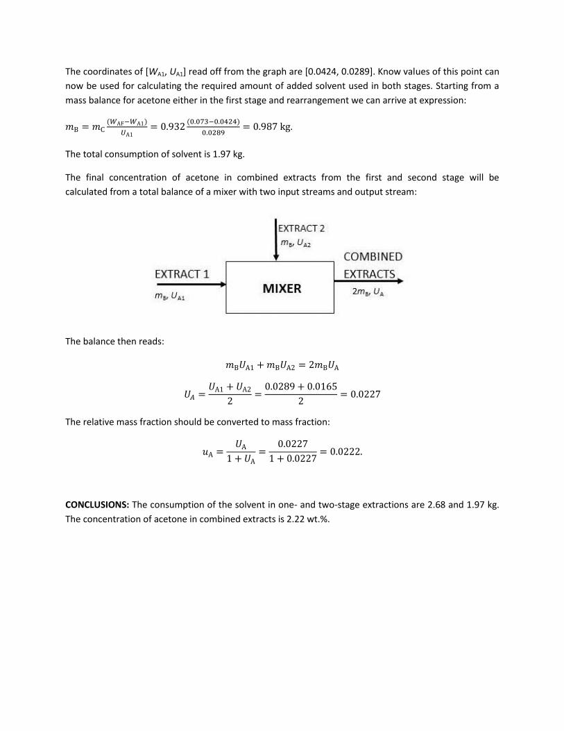
The final concentration of acetone in combined extracts from the first and second stage will be
calculated from a total balance of a mixer with two input streams and output stream:
The balance then reads:
𝑚B𝑈A1 + 𝑚B𝑈A2 = 2𝑚B𝑈A
𝑈𝐴 =𝑈A1 + 𝑈A2
2=
0.0289 + 0.0165
2= 0.0227
The relative mass fraction should be converted to mass fraction:
𝑢A =𝑈A
1 + 𝑈A=
0.0227
1 + 0.0227= 0.0222.
CONCLUSIONS: The consumption of the solvent in one- and two-stage extractions are 2.68 and 1.97 kg.
The concentration of acetone in combined extracts is 2.22 wt.%.

Calculation of HETP (height equivalent to theoretical plate)
Determine HETP of a counter-current rotational disc column 2.7 m high. Water phase containing 7 wt. %
of acetone and o-xylene phase containing 0.5 wt. % of acetone enter the column. The content of acetone
in the output water and o-xylene phases is 1.95 and 3.85 wt. %, respectively. What is the ratio of mass
flow rates of the entering phases? What is the maximum possible concentration of acetone in the leaving
extract? The extractor is operated at 30 °C.
DATA: A: extracted component, B: added solvent, C: original solvent, mass fraction of acetone in the
feed wAF =0.07; mass fraction of acetone in the solvent uAS = 0.005; mass fraction of acetone in the
rafinate wAN = 0.0195; mass fraction of acetone in the extract uA1 = 0.0385; the height of the column
h = 2.7 m. Equilibrium for this system can be found on:
http://uchi.vscht.cz/index.php/en/studium/uplatneni-absolventu/e-tabulky (data copied in the table
below). The equilibrium data suggests the immiscibility of the solvents which automatically leads to the
use of relative mass fractions.
Equilibrium:
SCHEMATICS of the problem: A schematic of a real counter-current
extraction column with rotational discs on the left, a schematic of the
problem used in ca
lculation on
the right.
The density of o-xylene is lower than that of water. Therefore, o-xylene
is the lighter phase and water is the heavier phase.
Mass fraction of acetone Relative mass fraction of acetone
Water phase Xylene phase Water phase Xylene phase
0.0091 0.0060 0.0092 0.0060
0.0180 0.0119 0.0183 0.0120
0.0357 0.0231 0.0370 0.0236
0.0519 0.0368 0.0547 0.0382
0.0796 0.0619 0.0865 0.0660
0.0900 0.0685 0.0989 0.0735
0.1590 0.1367 0.1891 0.1583
0.2200 0.2005 0.2821 0.2508

Solution:
We will use graphical method to solve the problem. In the first step, we will draw equilibrium curve using
the data from the table above. Because the solvents are immiscible (inferred from the equilibrium data)
we will use relative mass fractions in calculations. In the figure below, the equilibrium is represented
with a red curve that connects the equilibrium data from the table. To recall, the streams leaving a
theoretical plate are in equilibrium, i. e. the composition of these streams is also equilibrium
composition (red line in the schematic above). In the next step we will draw operational line. This
operational line corresponds to the mass balance of the extractor. The compositions of streams that are
on the same side of a stage has to lie on this line (orange line in the schematic above). The knowledge of
compositions of all streams leaving or entering the extractor allows us to draw to operational line in the
graph. This operational line connects points [WAF, UA1] and [WAN, UAS].
𝑊AF =𝑤AF
1 − 𝑤AF=
0.07
1 − 0.07= 0.073
𝑊AN =𝑤AN
1 − 𝑤AN=
0.0195
1 − 0.0195= 0.02
𝑈AS =𝑢AS
1 − 𝑢AS=
0.005
1 − 0.005= 0.005
𝑈A1 =𝑢A1
1 − 𝑢A1=
0.0385
1 − 0.0385= 0.04
To obtain the number of theoretical plates we will solve the problem by finding the compositions of all
streams that enter or leave each of the theoretical plates. We will start on the left of the column (stage
1) where the composition of the feed and extract are given by a point [WAF, UA1]. We will find the
composition of the water phase leaving the stage one by plotting a line parallel to x axis starting in point
[WAF, UA1] and ending in the corresponding point lying on the equilibrium line. This point has coordinates
[WA1, UA1]. Now using the operational line, we will find the composition of the o-xylene phase entering
stage 1. We will simply plot a line parallel to y axis that starts in point [WA1, UA1] and ends in the
corresponding point lying on the operational line. This point has coordinates [WA1, UA2]. We repeat this
process until we get into or beyond the point [WAN, UAS]. We see that we obtained three full “stairs”
corresponding to three full theoretical plates and part of the forth one. To quantify how much of the
forth step we obtained we simply evaluate the ratio of LM
KM =𝑊3−𝑊AN
𝑊3−𝑊4= 0.65. The extraction column,
thus, has 3.65 theoretical plates. To evaluate HETP, we divide the height of the column with the number
of theoretical plates: 𝐻𝐸𝑇𝑃 =ℎ
𝑁T=
2.7
3.65= 0.74 𝑚.
The ratio of the mass flow rates of the entering phases (i. e. mass flow rate of the feed and the mass flow
rate of the added solvent) will be calculated from: ��F
��S=
��AF+��C
��AS+��B=
𝑊AF��C+��C
𝑈AS��B+��B=
��C
��B
(1+𝑊AF)
(1+𝑈AS) where the
ratio ��C
��B will be evaluated from the component balance of A for the whole extractor:
��C
��B=
(𝑈A1−𝑈AS)
(𝑊AF−𝑊AN)=
(0.04−0.005)
(0.075−0.02)= 0.63. The required ratio of mass flow rates is:
��F
��S= 0.63
(1+0.075)
(1+0.005)= 0.67.
We obtain maximum concentration of acetone in the extract when mB corresponds to the minimum
consumption of the solvent mB,min. In the graphical solution, the operational line with mB,min (it is the

operational line crossing point [WAN, UAS] with maximal possible slope) is plotted with dashed black line.
We will read off UA1,max = 0.0545. The mass fraction is then:
𝑢 =𝑈A1
1−𝑈A1=
0.0545
1−0.0545= 0.052.
Graphical solution of the given problem.
Conclusions: The HETP of the column is 0.74 m, the ratio of mass flow rates of entering phases is The
HETP of the column is 0.74 m, the ratio of mass flow rates of entering phases is 0.67 and the maximum
possible concentration of acetone in extract is 5.2 wt. %.

DISTILLATION
Calculation of liquid – vapor equilibrium
Compare calculated boiling and dew points of a mixture of aniline and benzene containing 30 mol.% of
benzene with experimental data (at normal pressure). Calculate the relative volatility AB for the mixture
of benzene and aniline from the tabulated experimental data and compare with relative volatility
calculated from saturated vapor pressures of pure components AB = pA°/ pB
°.
Solution:
Benzene will be component A and aniline component B. We know the total pressure p =101325 Pa and
the molar fraction of benzene in the liquid xA = 0.3 for determining the boiling point Tb and in the vapor
yA = 0.3 for determining the dew point Td. We will find the experimental data in a table available on
departmental website (place the reference). These data are for equilibrium composition of a mixture of
benzene – aniline at normal pressure:
xA = 0.3 ----> yA = 0.94; Tb = 108.4°C
yA = 0.3 ----> xA = 0.0237; Td = 172.1°C (using interpolation).
Next, we will use Antoine equation to calculate the saturated vapor pressures. The coefficients for
Antoine equation for both components can also be found in a table on departmental website:
𝑝A° (𝑇) = exp (13.82649 −
2755.641
(𝑇 − 53.989))
𝑝B° (𝑇) = exp (15.17245 −
4238.575
(𝑇 − 56.277)
where the temperature is in Kelvins and the saturated vapor pressures of components in kPa.
1. We will calculate the boiling point of the mixture for xA = 0.3 from equation:
101.325 = 0.3𝑝A° (𝑇𝑏) + 0.7𝑝B
° (𝑇𝑏)
After solving the equation, we obtain the boiling point Tb = 394K = 120.9°C. The corresponding
equilibrium composition of the vapor phase at this temperature is according to the Raoult law
equal to: 𝑦A = 𝑥A𝑝A
° (𝑇𝑏)
𝑝= 0.3
𝑝A° (394)
103.325= 0.9045
2. The dew point of the mixture will be found in a similar way for yA = 0.3 from equation:
1 = 0.3101.325
𝑝A° (𝑇𝑑)
+ 0.7101.325
𝑝B° (𝑇𝑑)
The dew point is: Td = 445.9K = 172.8°C. The equilibrium composition of the liquid phase at this
temperature is according to Raoult law: 𝑥A = 𝑦A𝑝
𝑝A° (𝑇𝑑)
= 0.3101.325
𝑝A° (445.9)
= 0.0340

3. The relative volatility at 108.4°C calculated from the experimental data is equal to:
𝛼AB =𝑦A/𝑥A
𝑦B/𝑥B=
0.94/0.3
0.06/0.7= 36.6. Relative volatility calculated from the saturated vapor pressures
of components is:𝛼AB =𝑝A
° (381.55)
𝑝B° (381.55)
=224.21
8.51= 26.3.
Calculation of flash distillation
Flash distillation is used to obtain liquid phase containing 80 mol.% of toluene from a mixture with
composition of 50 mol.% of acetone and 50 mol.% of toluene. The process is adiabatic under the
pressure of 101325 Pa. Find the temperature of the flash distillation and the composition of the
distillate. Calculate the required temperature of the feed and the relative amount of obtained vapor and
liquid phase.
Schematics:
Solution:
Component A: acetone, component B: toluene; the composition of the streams: zAF = 0.5; xB = 0.8 and
the pressure in the drum is p = 101325 Pa. We will choose nF = 1 mol/s. The composition of the vapor
phase can be obtained from equilibrium for given composition of the liquid phase xA = 1 – xB = 0.2 and
pressure of 101325 Pa. The composition of the vapor phase is yA = 0.6553 and the temperature of the
distillation is T = 82.86°C.
We will use molar balances to calculate molar flow rates of the vapor and liquid phases:
1 = ��v + ��L
1 ∙ 0.5 = 0.2��L + 0.6553��V
By solving this set of two equations with two unknowns we get: nL = 0.528 mol/s and nV = 0.472 mol/s.
The required temperature of the feed will be calculated from enthalpy balance. The mean molar heat
capacities and enthalpies are:
⟨𝑐𝑝A(𝑙)
(41℃)⟩ = 2.25 kJ/kg/K = 130.6 J/mol/K, ∆ℎvap,A(82.8℃) = 29.7 kJ/mol
⟨𝑐𝑝B(𝑙)
(41℃)⟩ = 1.75 kJ/kg/K=161 J/mol/K, ∆ℎvap,B(82.8℃) = 34.8 kJ/mol
FEED
nF, zAF, hF, TF
VAPOR
nV, yA, hv, T
LIQUID nL, xA, hL, T
QT = 0
p = 101.325 kPa

The molar enthalpies of the feed, liquid and vapor with respect to the reference temperature of
TREF = 0°C and reference liquid state are:
ℎF = 𝑧AF ⟨𝑐𝑝A(𝑙)
⟩ (𝑇F − 𝑇REF) + 𝑧BF ⟨𝑐𝑝B(𝑙)
⟩ (𝑇F − 𝑇REF) = 0.5 ∙ 130.6 ∙ (𝑇F − 0) + 0.5 ∙ 161 ∙ (𝑇F − 0) =
145.8 ∙ (𝑇F − 0)
ℎL = 𝑥A ⟨𝑐𝑝A(𝑙)⟩ (𝑇 − 𝑇REF) + 𝑥B ⟨𝑐𝑝B
(𝑙)⟩ (𝑇 − 𝑇REF) = 0.2 ∙ 130.6 ∙ (82.86 − 0) + 0.8 ∙ 161 ∙ (82.86 − 0)
= 12837 J/mol
ℎV = 𝑦A ⟨𝑐𝑝A(𝑙)⟩ (𝑇 − 𝑇REF) + 𝑥B ⟨𝑐𝑝B
(𝑙)⟩ (𝑇 − 𝑇REF) + 𝑦A∆ℎvap,A + 𝑦A∆ℎvap,A
= 0.6553 ∙ 130.6 ∙ (82.86 − 0) + (1 − 0.6553) ∙ 161 ∙ (82.86 − 0) + 0.6553 ∙ 29700
+ (1 − 0.6553) ∙ 34800 = 43148 J/mol
By substituting into the enthalpy balance we arrive at:
1 ∙ 145.8 ∙ (𝑇F − 0) = 0.472 ∙ 12837 + 0.528 ∙ 43148
and calculate the temperature of the feed: TF = 197.8°C.
If the tabulated equilibrium data were not available, we could use Raoult law to estimate the
composition of the vapor phase: 1 = 𝑥A𝑝A
° (𝑇)
𝑝+ 𝑥B
𝑝B° (𝑇)
𝑝 , where the saturated vapor pressures for A and
B are: 𝑝A° (𝑇) = exp (14.37283 −
2787.488
(𝑇−43.486)); 𝑝B
° (𝑇) = exp (13.98998 −3090.782
(𝑇−53.963)).
By solving the equation above we arrive at T = 363.46 K = 90.31°C and yA = 0.5674.

Batch distillation with unknown composition of the liquid phase
Batch distillation at normal pressure is used to process 100 kg of a mixture with composition of 18 wt.%
of ethanol and 82 wt.% of water. How many kilograms of distillate with mean composition of 48 wt.% of
ethanol will be obtained and how much ethanol will transfer into the distillate? At what temperature do
we have to stop the distillation? Assume, that the output vapor is in equilibrium with the liquid phase.
Solution:
A: ethanol, B: water; Because we will not use Raoult law or any relations derived from it we can solve the
problem in mass balances: mF = 100 kg (initial weight of the batch); wAF = 0.18 (initial mass fraction of A
in the batch); wAD = 0.48 (required mean mass fraction of ethanol in the distillate)
The mass balances are:
𝑚F = 𝑚D + 𝑚W
𝑚F𝑤AF = 𝑚D��AD + 𝑚W𝑤AW
The differential mass balance is:
ln𝑚F
𝑚W= ∫
d𝑤A
𝑢A − 𝑤A
𝑤AF
𝑤AW
where uA is the mass fraction of ethanol in vapor which is in equilibrium with wA. By substituting into the
equations above, we get:
100 = 𝑚D + 𝑚W
100 ∙ 0.18 = 𝑚D��AD + 𝑚W𝑤AW
ln100
𝑚W= ∫
d𝑤A
𝑢A − 𝑤A
𝑤AF=0.18
𝑤AW
We will calculate the solution for the set of equations above for a few chosen values of wAw. The
equilibrium data for the system water – ethanol are available on the departmental website. Chosen
values wA and uA will be written into a table below. To calculate the integral in the third equation, we will
use a trapezoid method. We will integrate in the intervals given by the equilibrium data. The integrated
function 1/(uA – wA) and the course of integration will be written into the table.
wA uA t/°C 1/( uA -wA) Sk sum(Sk) mw mD wAD
0.18 0.5916 86.21 2.430 0 100 0 0.5916
0.15 0.5641 87.21 2.415 S1 = 0.07268 0.07268 92.99 7.01 0.5780
0.1 0.4911 89.60 2.557 S2 = 0.12430 0.19698 82.12 17.88 0.5474
0.05 0.3541 93.36 3.288 S3 = 0.14612 0.34310 70.96 29.04 0.4977
0.03 0.2581 95.53 4.384 S4 = 0.07672 0.41982 65.72 34.28 0.4676
0.01 0.1094 98.31 10.06 S5 = 0.14444 0.56426 56.88 43.12 0.4043

The column Sk is an approximation of the integral with trapezoid rule, e. g. the integral S3 is:
𝑆3 = ∫d𝑤A
𝑢A − 𝑤A
0.1
0.05
= (0.1 − 0.05)(2.557 + 3.288)
2= 0.14612
The column sum(Sk) is the sum of areas of several trapezoids, e. g. on a row for wAW = 0.05 we have:
∑ 𝑆k = ∫d𝑤A
𝑢A − 𝑤A= 𝑆1 + 𝑆2 + 𝑆3 =
0.18
0.05
∫d𝑤A
𝑢A − 𝑤A
0.18
0.15
+ ∫d𝑤A
𝑢A − 𝑤A
0.15
0.10
+ ∫d𝑤A
𝑢A − 𝑤A
0.10
0.05
We will estimate the solution wAW = 0.0382 from the table since at this composition of the liquid phase
the mean mass fraction of A in the distillate is wAD = 0.48. We will obtain mD = 32.10 kg of the distillate.
The batch distillation will be terminated at the temperature of t = 94.64°C. The fraction of ethanol that
has transferred into the distillate is: 𝑚D��AD
𝑚F𝑤AF∙ 100% =
32.10∙0.48
100∙0.18∙ 100% = 85.6% .
The equilibrium liquid-vapor for the system ethanol – water.
The integration of 1/(uA-wA) using the trapezoid rule.

DRYING
Calculation of drying in a tray dryer
A sample containing 2.5 kg of a dry material and 0.67 kg of water was inserted in a tray dryer. The critical
and the equilibrium moisture contents of the material obtained from experimental data were WAc = 0.14
and WA* = 0.05. The mass of the sample decreased by 0.07 kg after 10 minute drying in the I. period.
Calculate: a) period of time needed to reach the moisture content of WA = 0.07, b) the moisture content
after 70 min. of drying. Assume linear dependence of the drying rate on the moisture content of the
material for the II. period of drying.
Solution: a)
The initial moisture content of the material is WA0 = mA0/mC = 0.67/2.5 =0.268 and the critical one is
WAc = 0.14. The drying rate of the I. period of drying is NAc = (mA/mC)/ =(0.07/2.5)/10 = 2.8 × 10⁻³ min-1.
The period of time for the first period of drying will be calculated according to the equation:
𝜏1 =𝑊𝐴0 − 𝑊𝐴𝑐
𝑁𝐴𝑐=
0.268 − 0.14
2.8 × 10−3= 45.7 min
The period of time in the second period for drying from WAc = 0.14 to WA = 0.07 will be calculated from:
𝜏II =𝑊𝐴𝑐 − 𝑊𝐴
∗
𝑁𝐴𝑐ln
𝑊𝐴𝑐 − 𝑊𝐴∗
𝑊𝐴𝜏 − 𝑊𝐴∗ =
0.14 − 0.05
2.8 × 10⁻³ln
0.14 − 0.05
0.07 − 0.05= 53.7 min
The total period of time of drying is + = 45.7 + 53.7 =99.4 min.
b)
The period of time of drying in the first period is the same as in case a). In the second period the time of
drying is = 70 – 45.7 = 24.3 min. On substituting into the equation for the second period of drying we
get:
24.3 =0.14 − 0.05
2.8 × 10⁻³ln
0.14 − 0.05
𝑊𝐴𝜏 − 0.05= 53.7 min
By solving this equation for WAwe obtain the final moisture content 0.092.
Enthalpy balance of the continuous dryer
5000 kg/hour of a wet material enters a continuous dryer. The material contains 45 wt. % of water.
3000 kg/hour of the material leaves the dryer. The highest allowed temperature of the material is 30°C
and the critical moisture content of water is 5 wt. %. Air with temperature of 15°C and temperature of
the dew point of 8°C is heated in a preheater. The relative humidity of air at the dryer outlet is 80%.
Determine the consumption of air and the required heat input into the preheater. Assume no heat loss
in the preheater and the dryer.
DATA: mmat,i = 5000 kg/hour; mmat,e = 3000 kg/hour; wAi = 0.45; wAi = 0.05; t0 = 15°C; tDP,0 = 8°C;Ae = 80%;
tmax = 30°C;
We are to calculate: mair,0 = ?; Qk
SOLUTION:
Mass flow rate of dry material mC is:
��C = (1 − 𝑤Ai)��mat,i = (1 − 0.45) ∙ 5000 = 2750 kg/hour
The moisture content of the input and output material and the critical moisture content are:
𝑊Ai =𝑤Ai
1 − 𝑤Ai=
0.45
1 − 0.45= 0.8182
𝑊Ae =��mat,e − ��C
��C=
3000 − 2750
2750= 0.0909
𝑊Ac =𝑤Ac
1 − 𝑤Ac=
0.05
1 − 0.05= 0.0526
The moisture content of the material leaving the dryer is larger than the critical one, WAe > WAc.
Therefore, the temperature of the material is equal to the temperature of the wet-bulb thermometer
and it must not exceed temperature of tw = tmax = 30°C. The temperature of the wet-bulb theromometer
limits the temperature of air entering the dryer ti. We will read off humidity, relative enthalpies and
temperatures of the streams from the humidity chart:
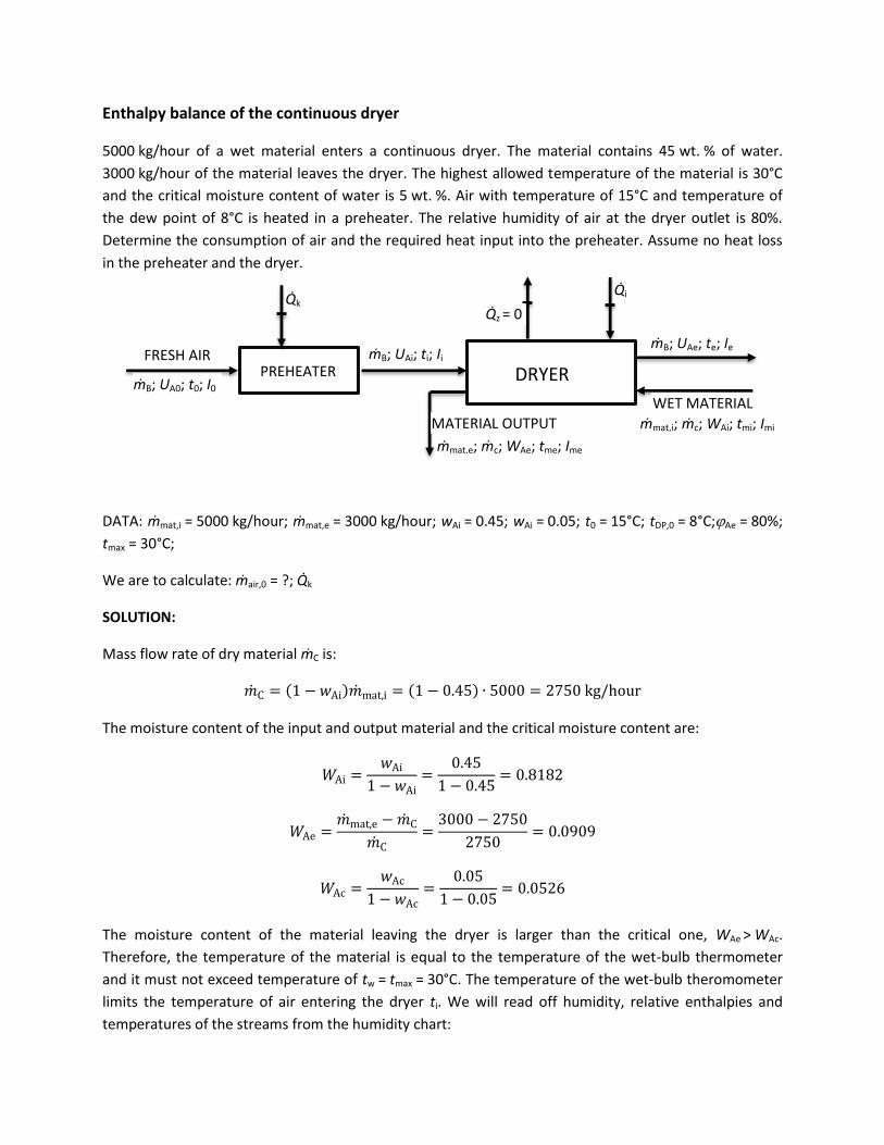
PREHEATER DRYER FRESH AIR
mB; UA0; t0; I0
mB; UAi; ti; Ii mB; UAe; te; Ie
WET MATERIAL
mmat,i; mc; WAi; tmi; Imi MATERIAL OUTPUT
mmat,e; mc; WAe; tme; Ime
Qk Qi
Qz = 0

1. fresh air: t0 = 15°C; tDP,0 = 8°C ----> UA0 = 0.00675; I0 = 32.14 kJ/kgB
2. air into the dryer: UAi = UA0 = 0.00675; tw = 30°C ----> ti = 80°C; Ii = 101 kJ/kgB
3. air form the dryer: Ie = Ii = 101 kJ/kgB; Ae = 80% -----> UAe = 0.0265; te = 33°C
The mass flow rate of the dry air will be calculated from the balance of the humidity/moisture content in
the dryer:
��B𝑈𝐴𝑖 − ��B𝑈𝐴𝑒 = ��C𝑊𝐴𝑒 − ��C𝑊𝐴𝑒
��B =��C(𝑊𝐴𝑒 − 𝑊𝐴𝑒)
(𝑈𝐴𝑖 − 𝑈𝐴𝑒)=
2750 ∙ (0.8182 − 0.0909)
(0.0265 − 0.00675)= 101.27
t
hour
The overall amount of air will be ��air,0 =��B
(1−𝑈A0)=
101.27
(1−0.00675)= 101.96 t/hour . The heat input into the
preheater will be calculated from the enthalpy balance of the preheater:
��k = ��B(𝐼𝑖 − 𝐼0) = 101.27 ∙ 103 ∙ (101 ∙ 103 − 32 ∙ 103) = 6.988 GJ/hour.
REACTORS
Tubular reactor (Dehydrogenation of ethylbenzene)
Dehydrogenation of ethylbenzene to styrene and hydrogen is carried out in a tubular reactor with inner
diameter of 10 cm and length of 50 m filled with particles of catalyst. The reaction proceeds at 600 DC
and 120 kPa. The reaction kinetics can be described by r=kcEB, where r is the reaction rate. Reaction rate
constant at 600 DC is k=0.0425s-1. The molar flow rates of ethylbenzene and water vapor at the inlet of
the reactor are ��𝐸𝐵,0 = 0.025𝑚𝑜𝑙
𝑠 and ��𝐻2𝑂,0 = 0.225
𝑚𝑜𝑙
𝑠. Calculate the conversion of ethylbenzene.
C6H6CH2-CH3⟶ C6H5CH=CH2+H2
Solution:
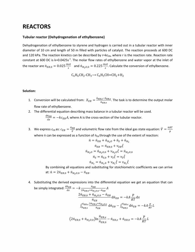
1. Conversion will be calculated from: 𝑋𝐸𝐵 =��𝐸𝐵,0−��𝐸𝐵,𝑒
��𝐸𝐵,0. The task is to determine the output molar
flow rate of ethylbenzene.
2. The differential equation describing mass balance in a tubular reactor will be used. d��𝐸𝐵
d𝑥= −𝑘𝑐𝐸𝐵𝐴, where A is the cross-section of the tubular reactor.
3. We express cEB as: 𝑐𝐸𝐵 =��𝐸𝐵
�� and volumetric flow rate from the ideal gas state equation: �� =
��𝑅𝑇
𝑝
where ṅ can be expressed as a function of ṅEB through the use of the extent of reaction:
�� = ��𝐸𝐵 + ��𝐻2𝑂 + ��𝑆 + ��𝐻2
��𝐸𝐵 = ��𝐸𝐵,0 + 𝜈𝐸𝐵��
��𝐻2𝑂 = ��𝐻2𝑂,0 + 𝜈𝐻2𝑂�� = ��𝐻2𝑂,0
��𝑆 = ��𝑆,0 + 𝜈𝑆�� = 𝜈𝑆��
��𝐻2= ��𝐻2,0 + 𝜈𝐻2
�� = 𝜈𝐻2��
By combining all equations and substituting for stoichiometric coefficients we can arrive
at: �� = 2��𝐸𝐵,0 + ��𝐻2𝑂,0 − ��𝐸𝐵.
4. Substituting the derived expressions into the differential equation we get an equation that can
be simply integrated: d��𝐸𝐵
d𝑥= −𝑘
��𝐸𝐵
2��𝐸𝐵,0+��𝐻2𝑂,0−��𝐸𝐵𝐴
2��𝐸𝐵,0 + ��𝐻2𝑂,0 − ��𝐸𝐵
��𝐸𝐵d��𝐸𝐵 = −𝑘𝐴
𝑝
𝑅𝑇d𝑥
∫2��𝐸𝐵,0+��𝐻2𝑂,0
��𝐸𝐵
��𝐸𝐵,𝑒
��𝐸𝐵,0 d��𝐸𝐵 − ∫ d��𝐸𝐵 = −𝑘𝐴
𝑝
𝑅𝑇𝐿
��𝐸𝐵,𝑒
��𝐸𝐵,0
(2��𝐸𝐵,0 + ��𝐻2𝑂,0)ln��𝐸𝐵,𝑒
��𝐸𝐵,0− ��𝐸𝐵,𝑒 + ��𝐸𝐵,0 = −𝑘𝐴
𝑝
𝑅𝑇𝐿
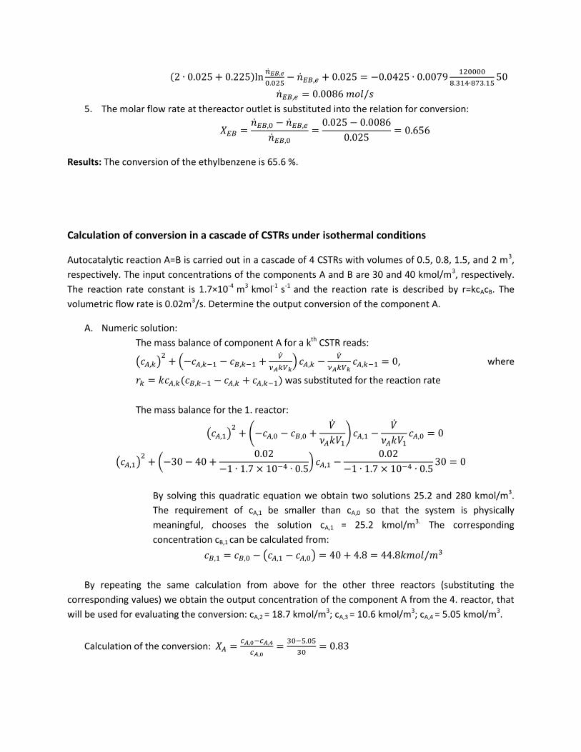
(2 ∙ 0.025 + 0.225)ln��𝐸𝐵,𝑒
0.025− ��𝐸𝐵,𝑒 + 0.025 = −0.0425 ∙ 0.0079
120000
8.314∙873.1550
��𝐸𝐵,𝑒 = 0.0086 𝑚𝑜𝑙/𝑠
5. The molar flow rate at thereactor outlet is substituted into the relation for conversion:
𝑋𝐸𝐵 =��𝐸𝐵,0 − ��𝐸𝐵,𝑒
��𝐸𝐵,0=
0.025 − 0.0086
0.025= 0.656
Results: The conversion of the ethylbenzene is 65.6 %.
Calculation of conversion in a cascade of CSTRs under isothermal conditions
Autocatalytic reaction A=B is carried out in a cascade of 4 CSTRs with volumes of 0.5, 0.8, 1.5, and 2 m3,
respectively. The input concentrations of the components A and B are 30 and 40 kmol/m3, respectively.
The reaction rate constant is 1.7×10⁻⁴ m3 kmol-1 s-1 and the reaction rate is described by r=kcAcB. The
volumetric flow rate is 0.02m3/s. Determine the output conversion of the component A.
A. Numeric solution:
The mass balance of component A for a kth CSTR reads:
(𝑐𝐴,𝑘)2
+ (−𝑐𝐴,𝑘−1 − 𝑐𝐵,𝑘−1 +��
𝜈𝐴𝑘𝑉𝑘) 𝑐𝐴,𝑘 −
��
𝜈𝐴𝑘𝑉𝑘𝑐𝐴,𝑘−1 = 0, where
𝑟𝑘 = 𝑘𝑐𝐴,𝑘(𝑐𝐵,𝑘−1 − 𝑐𝐴,𝑘 + 𝑐𝐴,𝑘−1) was substituted for the reaction rate
The mass balance for the 1. reactor:
(𝑐𝐴,1)2
+ (−𝑐𝐴,0 − 𝑐𝐵,0 +��
𝜈𝐴𝑘𝑉1) 𝑐𝐴,1 −
��
𝜈𝐴𝑘𝑉1𝑐𝐴,0 = 0
(𝑐𝐴,1)2
+ (−30 − 40 +0.02
−1 ∙ 1.7 × 10⁻⁴ ∙ 0.5) 𝑐𝐴,1 −
0.02
−1 ∙ 1.7 × 10⁻⁴ ∙ 0.530 = 0
By solving this quadratic equation we obtain two solutions 25.2 and 280 kmol/m3.
The requirement of cA,1 be smaller than cA,0 so that the system is physically
meaningful, chooses the solution cA,1 = 25.2 kmol/m3. The corresponding
concentration cB,1 can be calculated from:
𝑐𝐵,1 = 𝑐𝐵,0 − (𝑐𝐴,1 − 𝑐𝐴,0) = 40 + 4.8 = 44.8𝑘𝑚𝑜𝑙/𝑚3
By repeating the same calculation from above for the other three reactors (substituting the
corresponding values) we obtain the output concentration of the component A from the 4. reactor, that
will be used for evaluating the conversion: cA,2 = 18.7 kmol/m3; cA,3 = 10.6 kmol/m3; cA,4 = 5.05 kmol/m3.
Calculation of the conversion: 𝑋𝐴 =𝑐𝐴,0−𝑐𝐴,4
𝑐𝐴,0=
30−5.05
30= 0.83

B. Graphical solution:
1. We will rearrange the mass balance, so that it reads:
𝑟𝑘 =��
𝑉𝑘(𝑐𝐴,𝑘 − 𝑐𝐴,𝑘−1)
1
𝜈𝐴= −
��
𝑉𝑘(𝑐𝐴,𝑘 − 𝑐𝐴,𝑘−1)
At the same time the reaction rate is equal to: 𝑟 = 𝑘𝑐𝐴𝑐𝐵 = 𝑘𝑐𝐴(𝑐𝐴0 + 𝑐𝐵0 − 𝑐𝐴), and this reaction rate
can be plotted as a function of ca in an interval of 0 to 35 kmol/m3 (blue line in graph below). We will use
this graph to plot in the line given by the equation rk=f(cA,k) written for each of the four reactors (red
lines). To plot a line we need two points or a point and a slope. The slope is given by the ratio of ��
𝑉𝑘 and
one point is [cA,k-1, 0]. For the first reactor the slope is -0.02/0.5=-0.04 and the point has coordinates
[30,0]. The intersection of the curves described by r=f(cA) and r1=f(cA,1) gives the output concentration
cA,1. By repeating the same process for the other three reactors, we obtain concentration cA,4 that will be
used for calculating the output conversion.


