Download - Basic Concepts
Basic Concepts
Block diagram representation of control systems
Transfer functions Analysis of block diagrams P, PI and PID controllers ( Continuous
and discrete forms) Stability of feedback control systems
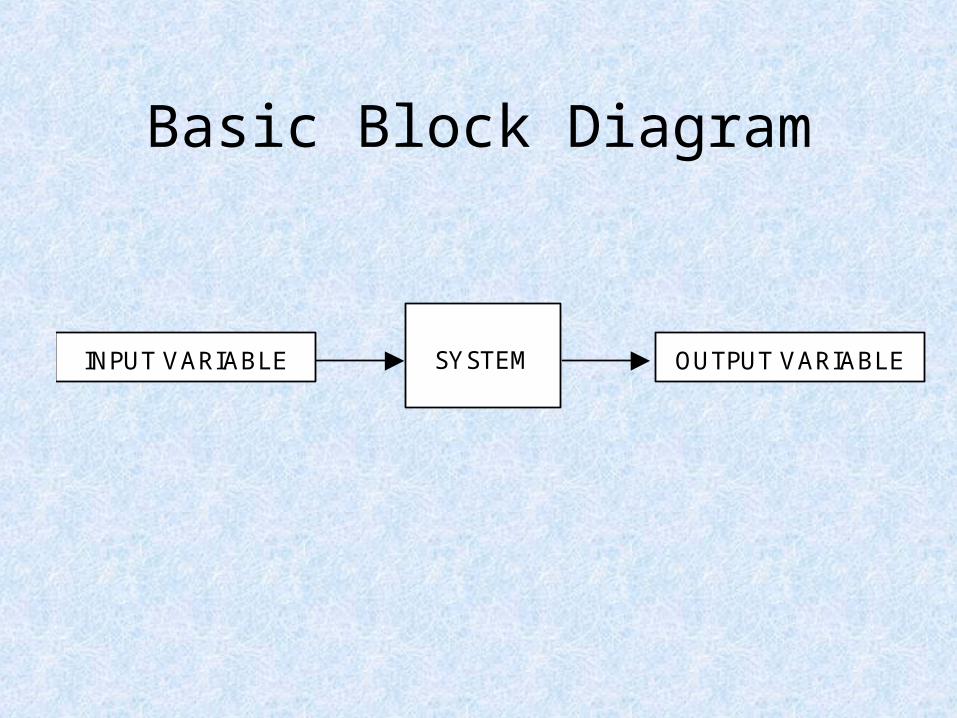
Basic Block Diagram
INPUT VARIABLE OUTPUT VARIABLESYSTEM
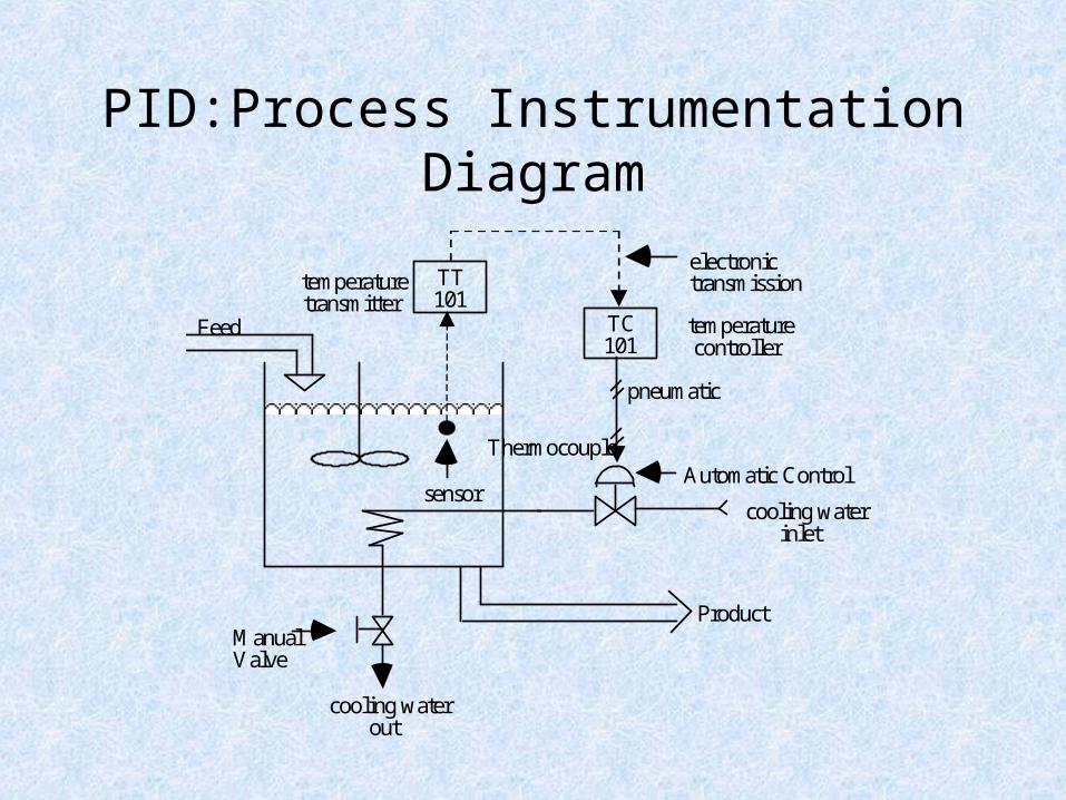
PID:Process Instrumentation Diagram
TT101
temperaturetransmitter
Thermocouple
TC101
temperaturecontroller
cooling waterinlet
cooling waterout
Feed
electronictransmissionline
ProductManualValve
sensor
pneumaticline
Automatic ControlValve
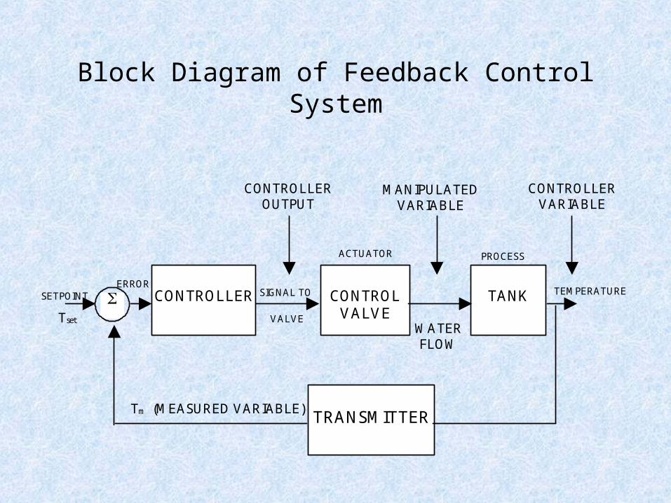
Block Diagram of Feedback Control System
CONTROLVALVE
TANKCONTROLLER
TRANSMITTER
WATERFLOW
VALVETset
SETPOINTERROR
ACTUATOR PROCESS
TEMPERATURE
Tm (MEASURED VARIABLE)
SIGNAL TO
CONTROLLEROUTPUT
MANIPULATEDVARIABLE
CONTROLLERVARIABLE
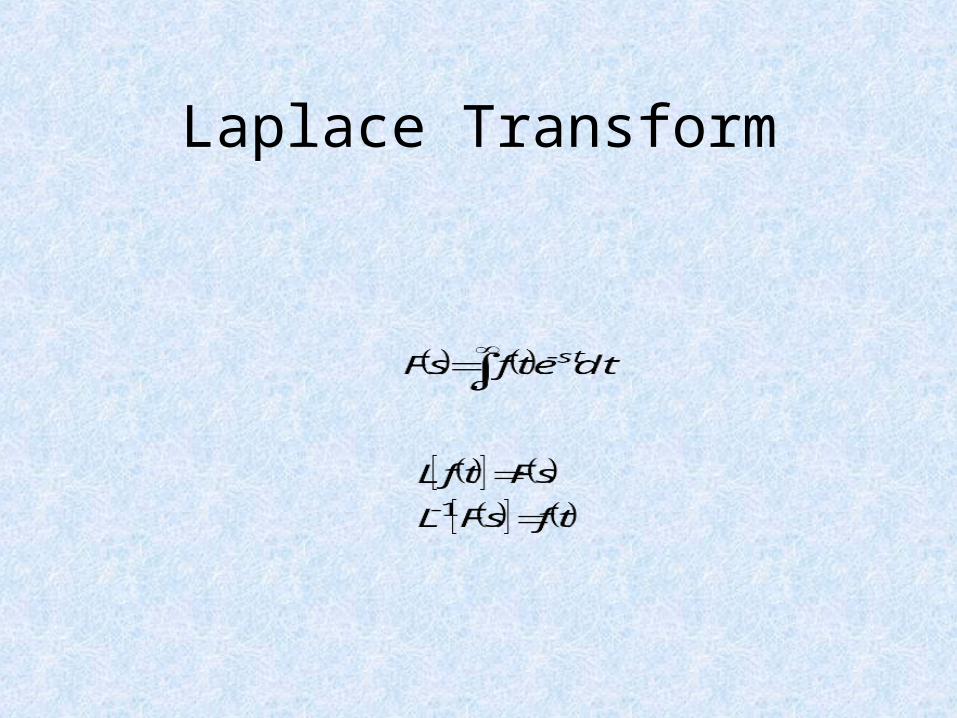
Laplace Transform
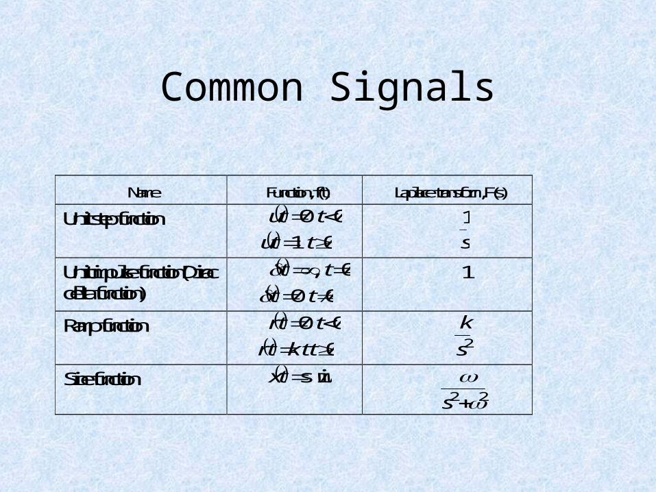
Common Signals
Name Function, f(t) Laplace transform, F(s)
Unit step function 0 0 ttu
0 1 ttu s
1
Unit impulse function(Diracdelta function)
0 , tt 0 0 tt
1
Ramp function 0 0 ttr
0 tkttr 2s
k
Sine function wttx sin 22
s
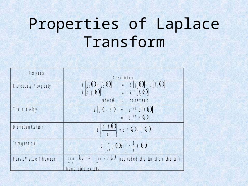
Properties of Laplace Transform
P r o p e r t yD e s c r i p t i o n
L i n e a r i t y P r o p e r t y
co n stan t w h ere
11
2121
K
tfLktfkL
tfLtfLtftfL
T i m e D e l a y sFe
tfLetfLs
s
D i f f e r e n t i a t i o n ofsFsd t
tfdL
I n t e g r a t i o n sFs
d ttfLt
o
1
F i n a l V a l u e T h e o r e m lim t
f t lim s 0
s F s
p r o v i d e d t h e l i m i t o n t h e l e f t
h a n d s i d e e x i s t s .
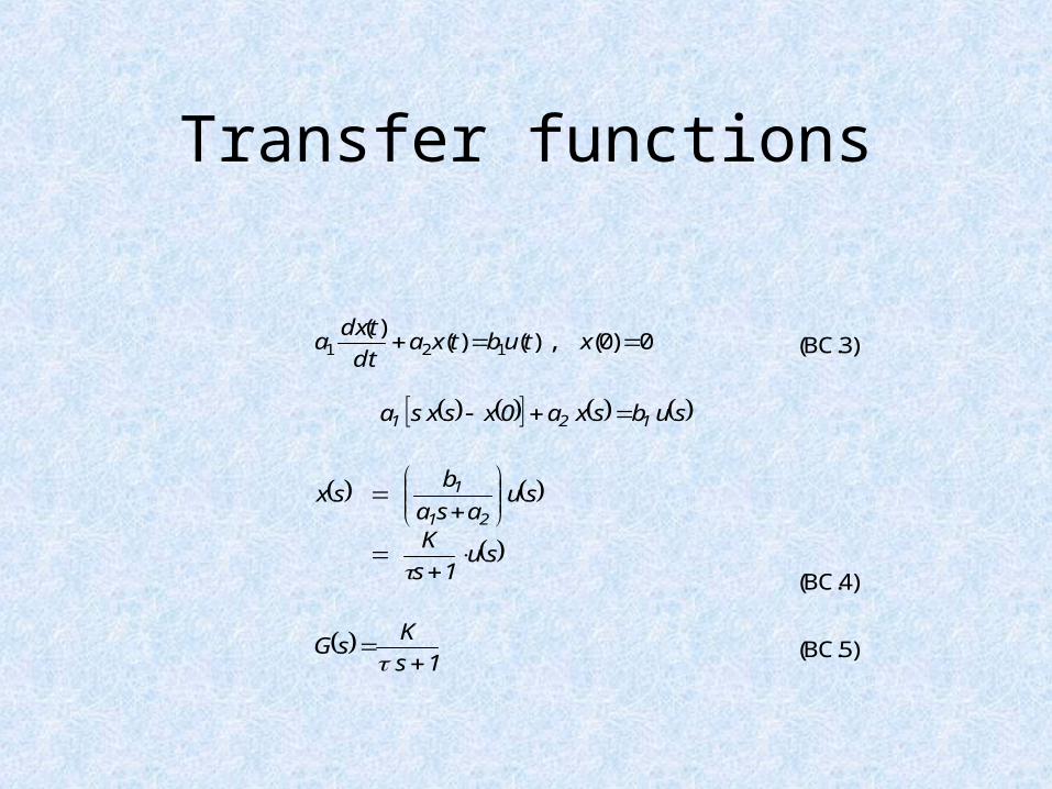
Transfer functions
0)0(),()()(
121 xtubtxadt
tdxa (BC.3)
subsxa0xsxsa 121
su1s
K
suasa
bsx
21
1
(BC.4)
1s
KsG
(BC.5)
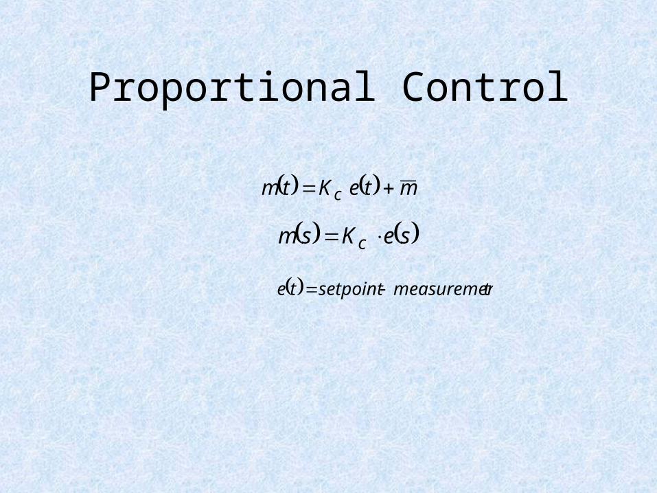
Proportional Control
mteKtm c
seKsm c
tmeasuremen setpoint te
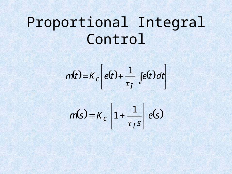
Proportional Integral Control
dt te teK tm
Ic
1
ses
KsmI
c
1
1
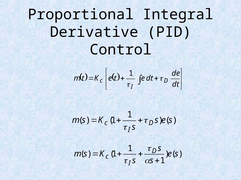
Proportional Integral Derivative (PID) Control
dt
de dt e te K tm D
Ic
1
)()1
1()( sess
Ksm DI
c
)()1
11()( se
s
s
sKsm D
Ic
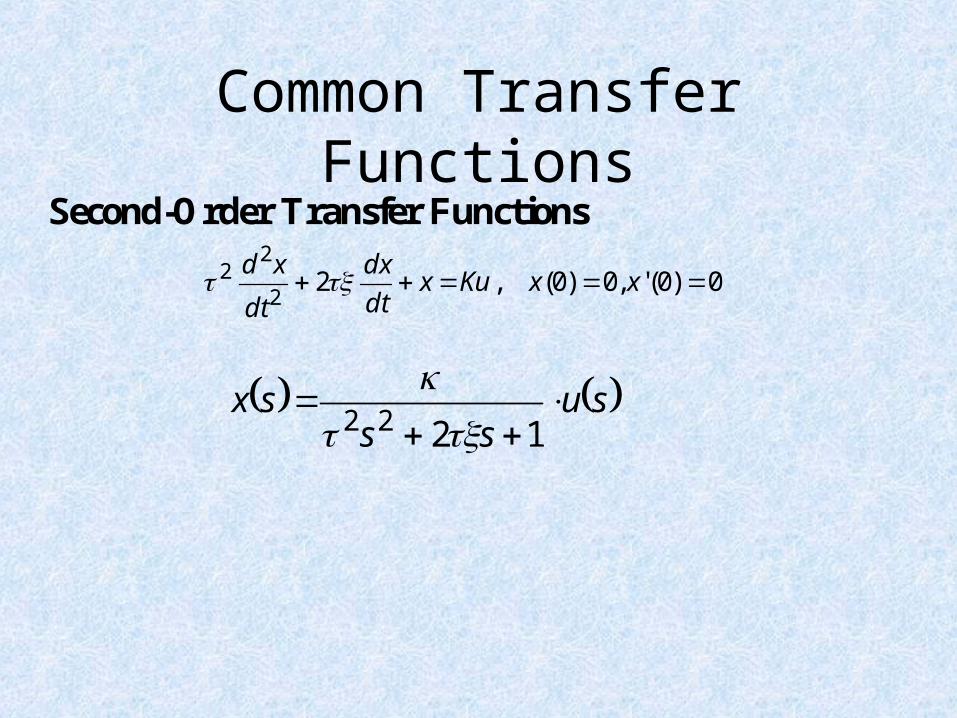
Common Transfer Functions
0)0(',0)0(,22
22 xxKu x
dt
dx
dt
xd
Second-Order Transfer Functions
su s s
sx
1222
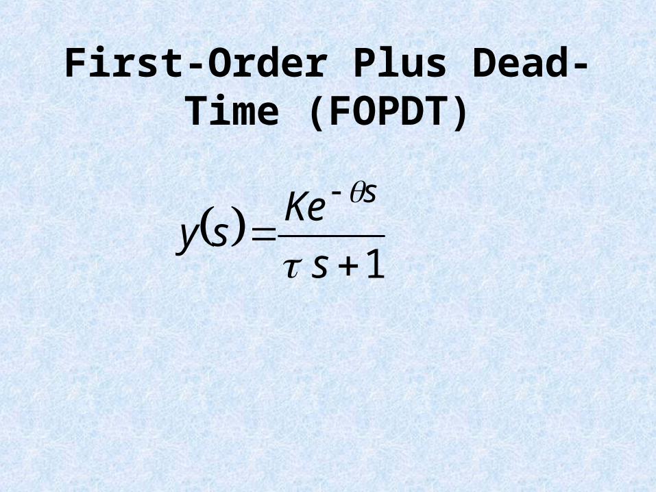
First-Order Plus Dead-Time (FOPDT)
1 s
Ke sy
s
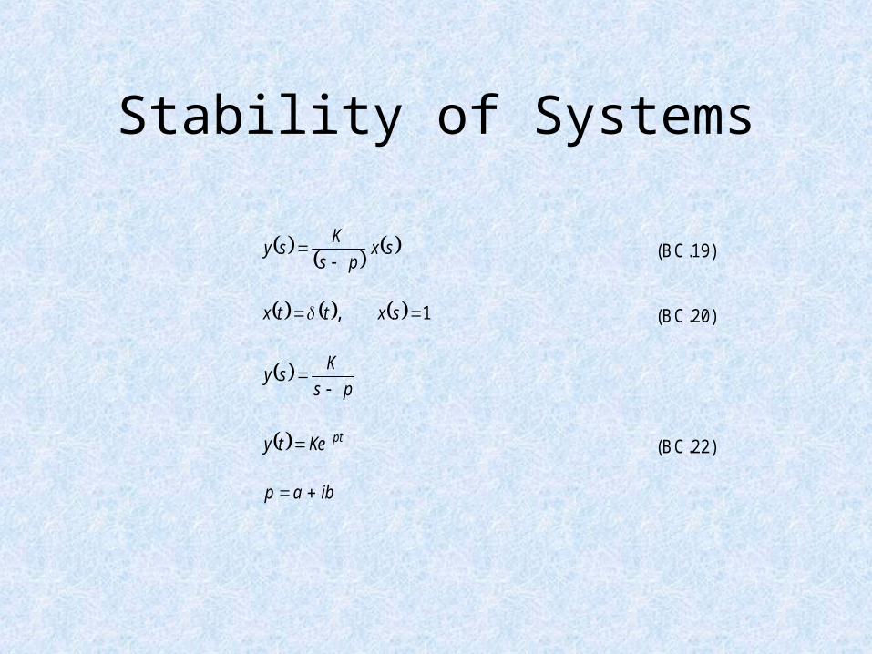
Stability of Systems
sxps
Ksy
(BC.19)
1, sxttx (BC.20)
ps
Ksy
ptKety (BC.22)
ibap
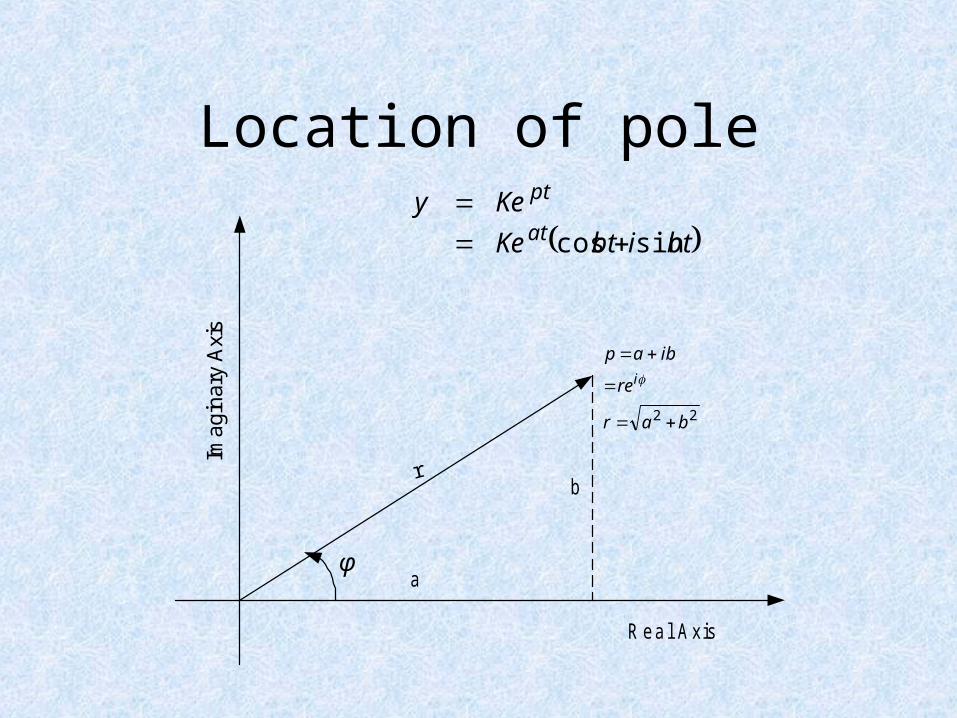
Location of pole
22 bar
re
ibapi
a
br
R eal A xis
Imag
inar
y A
xis
φ
btibtKe
Keyat
pt
sincos
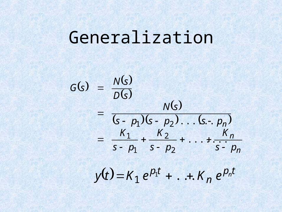
Generalization
n
n
n
ps
K
ps
K
ps
Kpspsps
sNsD
sNsG
.......
.......
2
2
1
1
21
tpn
tp neKeKty ...11
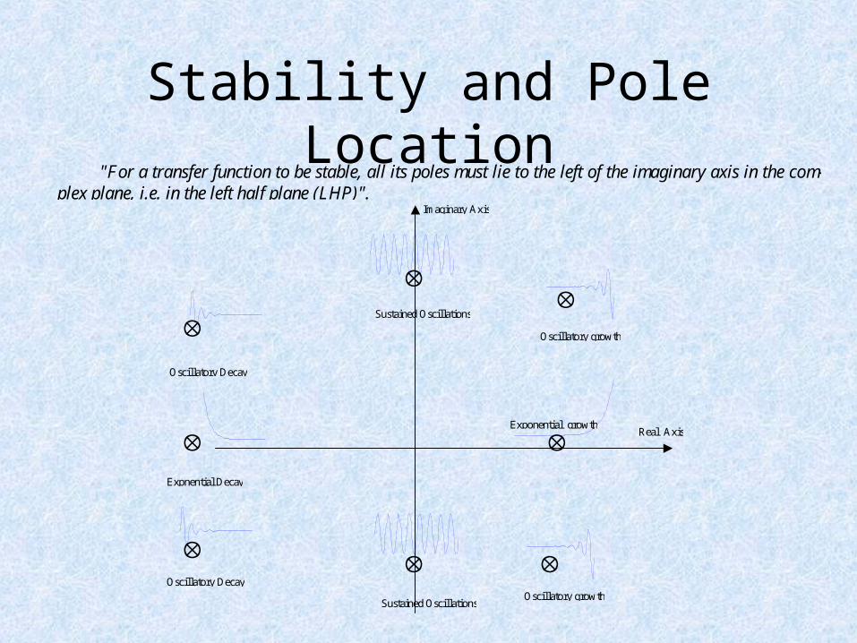
Stability and Pole Location
Imaginary Axis
Real Axis
Oscillatory growth
Exponential growth
Oscillatory growth
Expnential Decay
Oscillatory Decay
Oscillatory Decay
Sustained Oscillations
Sustained Oscillations
"For a transfer function to be stable, all its poles must lie to the left of the imaginary axis in the com-plex plane, i.e. in the left half plane (LHP)".
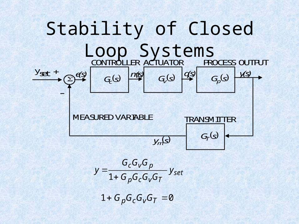
Stability of Closed Loop SystemsCONTROLLER ACTUATOR PROCESS OUTPUT
TRANSMITTERMEASURED VARIABLE
yset + e(s) m(s) q(s) y(s) sGc
G (s)
sGv sGp
sGT sym
-
01 Tvcp GGGG
setTvcp
pvcy
GGGG
GGGy
1
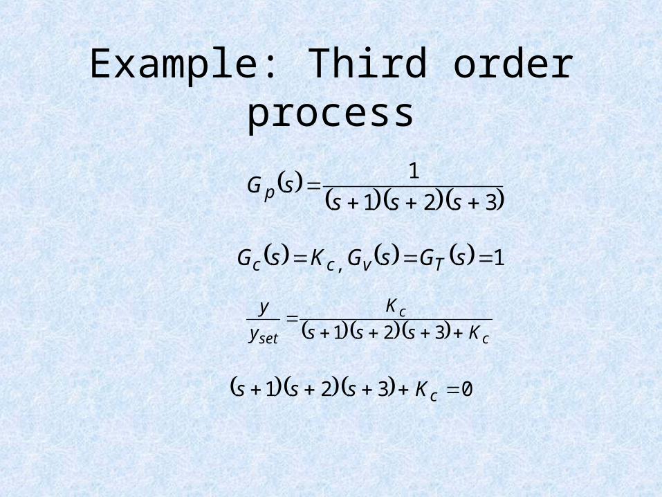
Example: Third order process
321
1
ssssGp
1, sGsGKsG Tvcc
c
c
set Ksss
K
y
y
321
0321 cKsss
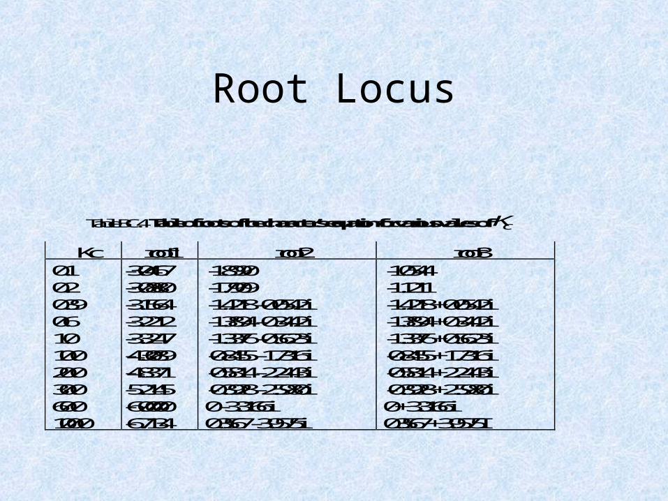
Root Locus
Table BC.4 Table of roots of the character’s equation for various valves of cK
Kc root1 root2 root30.10.20.390.61.010.020.030.060.0100.0
-3.0467-3.0880-3.1564-3.2212-3.3247-4.3089-4.8371-5.2145-6.0000-6.7134
-1.8990-1.7909-1.4218 - 0.0542i-1.3894 - 0.3442i-1.3376 - 0.5623i-0.8455 - 1.7316i-0.5814 - 2.2443i-0.3928 - 2.5980i0 - 3.3166i0.3567 - 3.9575i
-1.0544-1.1211-1.4218 + 0.0542i-1.3894 + 0.3442i-1.3376 + 0.5623i-0.8455 + 1.7316i-0.5814 + 2.2443i-0.3928 + 2.5980i0 + 3.3166i0.3567 + 3.9575I
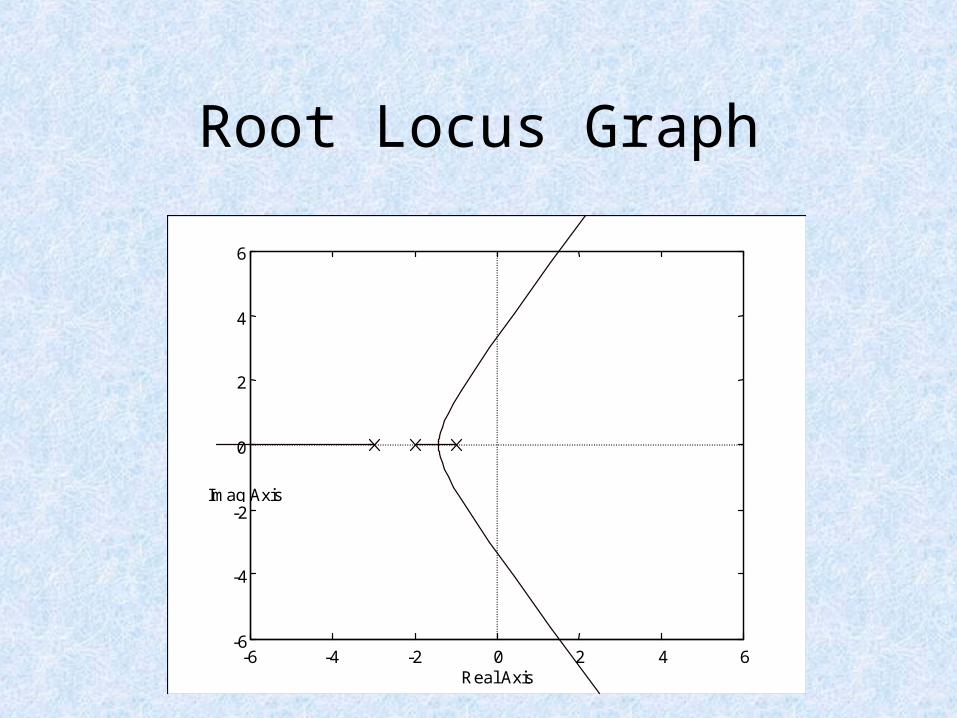
Root Locus Graph
-6 -4 -2 0 2 4 6-6
-4
-2
0
2
4
6
Real Axis
Imag Axis
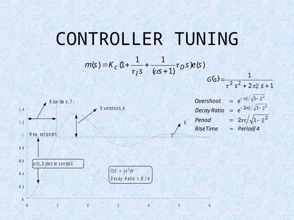
CONTROLLER TUNING)()
)1(
111()( ses
ssKsm D
Ic
0
0 .2
0 .4
0 .6
0 .8
1
1 .2
1 .4
0 1 2 3 4 5 6
N e w s e t p o i n t
O v e r s h o o t , AR i s e t i m e , T r
B
e ( t ) , E r r o r i n c o n t r o l
I S E e d t
D e c a y R a t i o B A
2
/
4PeriodTime Rise
Penod
eRatioDecay
eOvershoot
2
12
1
12
2
2
12
122
ss
sG
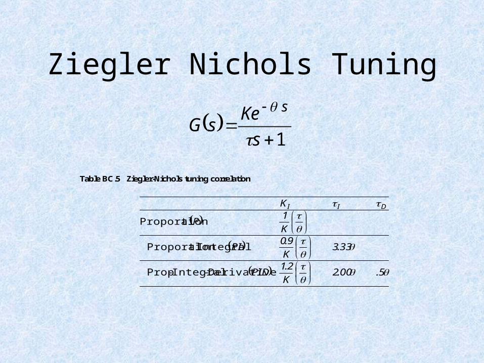
Ziegler Nichols Tuning
Table BC.5 Ziegler-Nichols tuning correlation
5.00.2K
2.1PID
33.3K
9.0PI
K
1P
K DII
Derivative-Integral-Prop
Integral alProportion
alProportion
1 s
Ke sG
s


