
Four-Faith Smart Power Technology Co., Ltd.
F2403 WCDMA/HSDPA/HSUPA IP MODEM
USER MANUAL
Four-Faith Smart Power Technology Co., Ltd.
ContentsContentsChapter 1 Brief Introduction of Product.......................................................................... 3
1.1 General................................................................................................................31.2 Features and Benefits......................................................................................... 31.3 Working Principle...............................................................................................41.4 Specifications..................................................................................................... 4
Chapter 2 Installation Introduction.................................................................................. 62.1 General................................................................................................................62.2 Encasement List................................................................................................. 62.3 Installation and Cable Connection..................................................................... 62.4 Power.................................................................................................................. 72.5 Indicator Lights Introduction............................................................................. 8
Chapter 3 Configuration...................................................................................................93.1 Configuration Connection.................................................................................. 93.2 Configuration Introduction.................................................................................93.3 Run the configure Tool: IP Modem Configure.exe............................................93.4 Re-power IP MODEM..................................................................................... 103.5 Configuration....................................................................................................10
3.5.1 Data Service Center Settings.................................................................103.5.2 IP MODEM Settings............................................................................. 123.5.3 Other Settings........................................................................................ 16
3.6 Functions.......................................................................................................... 193.7 Work State Switch............................................................................................ 20
Appendix........................................................................................................................ 20
Four-Faith Smart Power Technology Co., Ltd.
Chapter 1 Brief Introduction of Product
1.1 General
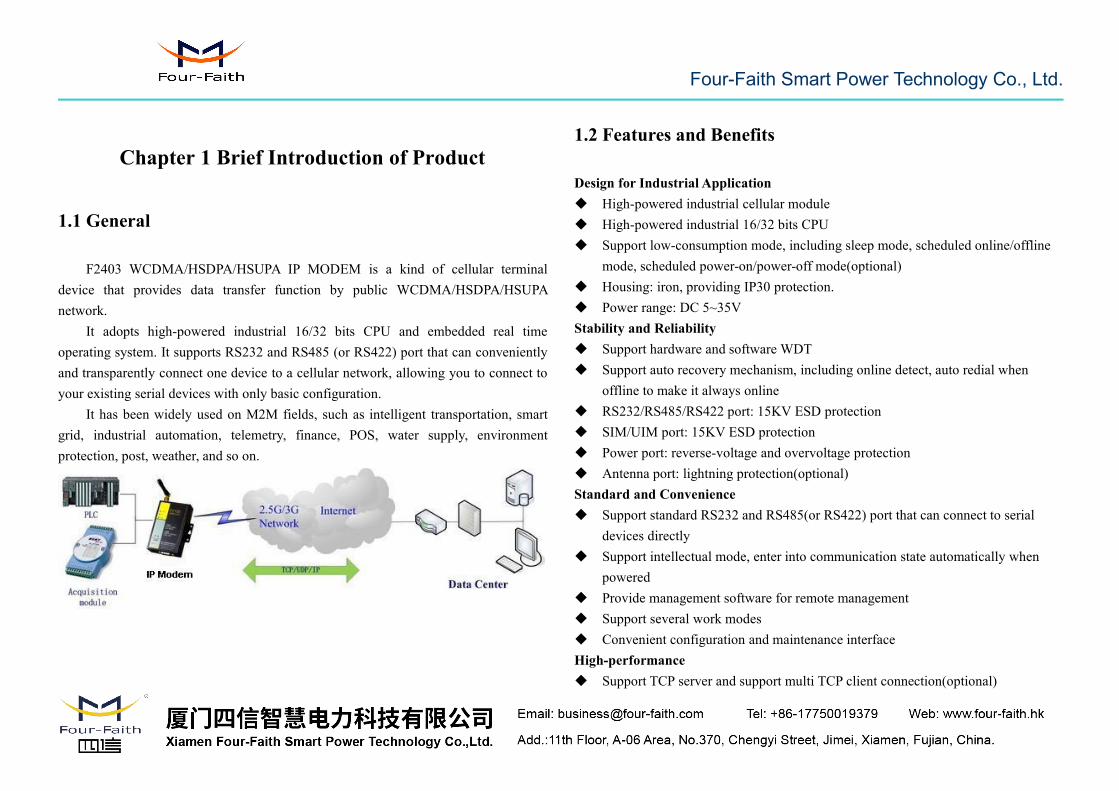
F2403 WCDMA/HSDPA/HSUPA IP MODEM is a kind of cellular terminaldevice that provides data transfer function by public WCDMA/HSDPA/HSUPAnetwork.
It adopts high-powered industrial 16/32 bits CPU and embedded real timeoperating system. It supports RS232 and RS485 (or RS422) port that can convenientlyand transparently connect one device to a cellular network, allowing you to connect toyour existing serial devices with only basic configuration.
It has been widely used on M2M fields, such as intelligent transportation, smartgrid, industrial automation, telemetry, finance, POS, water supply, environmentprotection, post, weather, and so on.
1.2 Features and Benefits
Design for Industrial Application High-powered industrial cellular module High-powered industrial 16/32 bits CPU Support low-consumption mode, including sleep mode, scheduled online/offline
mode, scheduled power-on/power-off mode(optional) Housing: iron, providing IP30 protection. Power range: DC 5~35VStability and Reliability Support hardware and software WDT Support auto recovery mechanism, including online detect, auto redial when
offline to make it always online RS232/RS485/RS422 port: 15KV ESD protection SIM/UIM port: 15KV ESD protection Power port: reverse-voltage and overvoltage protection Antenna port: lightning protection(optional)Standard and Convenience Support standard RS232 and RS485(or RS422) port that can connect to serial
devices directly Support intellectual mode, enter into communication state automatically when
powered Provide management software for remote management Support several work modes Convenient configuration and maintenance interfaceHigh-performance Support TCP server and support multi TCP client connection(optional)
Four-Faith Smart Power Technology Co., Ltd.
Support double data centers, one main and another backup Support multi data centers and it can support 5 data centers at the same time Support multi online trigger ways, including SMS, ring and data. Support link
disconnection when timeout Support dynamic domain name(DDNS) and IP access to data center Design with standard TCP/IP protocol stack Support APN/VPDN
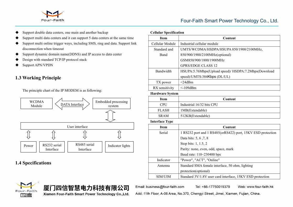
1.3 Working Principle
The principle chart of the IP MODEM is as following:
1.4 Specifications
Cellular SpecificationItem Content
Cellular Module Industrial cellular moduleStandard and
BandUMTS/WCDMA/HSDPA/HSUPA 850/1900/2100MHz,850/900/1900/2100MHz(optional)GSM850/900/1800/1900MHzGPRS/EDGE CLASS 12
Bandwidth HSUPA:5.76Mbps(Upload speed)/ HSDPA:7.2Mbps(Downloadspeed)/UMTS:384Kbps (DL/UL)
TX power <24dBmRX sensitivity <-109dBm
Hardware SystemItem ContentCPU Industrial 16/32 bits CPU
FLASH 1MB(Extendable)SRAM 512KB(Extendable)
Interface TypeItem ContentSerial 1 RS232 port and 1 RS485(orRS422) port, 15KV ESD protection
Data bits: 5, 6 ,7, 8Stop bits: 1, 1.5, 2Parity: none, even, odd, space, markBaud rate: 110~230400 bps
Indicator "Power", "ACT", "Online"Antenna Standard SMA female interface, 50 ohm, lighting
protection(optional)SIM/UIM Standard 3V/1.8V user card interface, 15KV ESD protection
Embedded processingsystem
WCDMAModule
Power RS232 serialInterface
Indicator lights
DATA Interface
User interface
RS485 serialInterface
Four-Faith Smart Power Technology Co., Ltd.
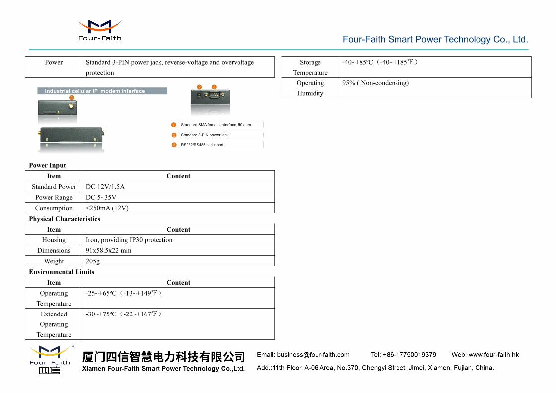
Power Standard 3-PIN power jack, reverse-voltage and overvoltageprotection
Power InputItem Content
Standard Power DC 12V/1.5APower Range DC 5~35VConsumption <250mA (12V)
Physical CharacteristicsItem Content
Housing Iron, providing IP30 protectionDimensions 91x58.5x22 mmWeight 205g
Environmental LimitsItem Content
OperatingTemperature
-25~+65ºC(-13~+149℉)
ExtendedOperatingTemperature
-30~+75ºC(-22~+167℉)
StorageTemperature
-40~+85ºC(-40~+185℉)
OperatingHumidity
95% ( Non-condensing)

Four-Faith Smart Power Technology Co., Ltd.
Chapter 2 Installation Introduction
2.1 General
The IP MODEM must be installed correctly to make it work properly.Warning: Forbid to install the IP MODEM when powered!
2.2 Encasement List
Name Quantity RemarkIP MODEM host 1Antenna 1Power adapter 1RS232 data cable 1 optionalRS485 data cable 1 optionalManual CD 1Certification card 1
Maintenance card 1
2.3 Installation and Cable Connection
Dimension: (unit: mm)
58.5
35
28
28
22 8
25
Ф3
Ф5
4
Installation of SIM/UIM card:Firstly power off the IP MODEM, and press the out button of the SIM/UIM card
outlet with a needle object. Then the SIM/UIM card sheath will flick out at once. PutSIM/UIM card into the card sheath (Pay attention to put the side which has metal pointoutside), and insert card sheath back to the SIM/UIM card outlet.
Warning: Forbid to install SIM/UIM card when powered!
Four-Faith Smart Power Technology Co., Ltd.
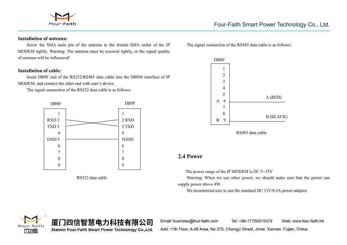
Installation of antenna:Screw the SMA male pin of the antenna to the female SMA outlet of the IP
MODEM tightly. Warning: The antenna must be screwed tightly, or the signal qualityof antenna will be influenced!
Installation of cable:Insert DB9F end of the RS232/RS485 data cable into the DB9M interface of IP
MODEM, and connect the other end with user’s device.The signal connection of the RS232 data cable is as follows:
The signal connection of the RS485 data cable is as follows:
2.4 Power
The power range of the IP MODEM is DC 5~35VWarning: When we use other power, we should make sure that the power can
supply power above 4W.We recommend user to use the standard DC 12V/0.5A power adaptor.
DB9F DB9F
RS232 data cable
1RXD 2TXD 3
4GND 5
6789
12 RXD3 TXD45GND6789
DB9F
RS485 data cable
12345
A 678
B 9
A (RED)
B (BLACK)
Four-Faith Smart Power Technology Co., Ltd.
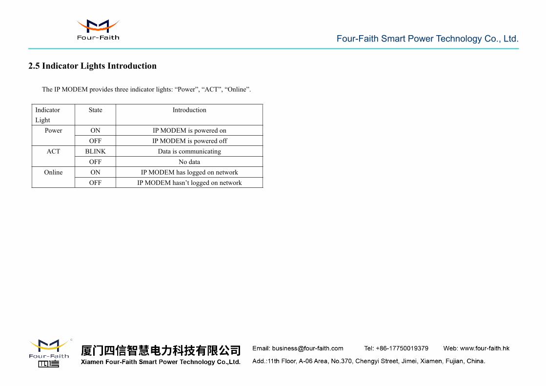
2.5 Indicator Lights Introduction
The IP MODEM provides three indicator lights: “Power”, “ACT”, “Online”.
IndicatorLight
State Introduction
Power ON IP MODEM is powered onOFF IP MODEM is powered off
ACT BLINK Data is communicatingOFF No data
Online ON IP MODEM has logged on networkOFF IP MODEM hasn’t logged on network

Four-Faith Smart Power Technology Co., Ltd.
Chapter 3 Configuration
3.1 Configuration Connection
Before configuration, it’s necessary to connect the IP MODEM with the configurePC by the shipped RS232 or RS232-485 conversion cable as following.
3.2 Configuration Introduction
There are two ways to configure the IP MODEM:Configuration software tool: All the settings are configured through the shipped
software tool. It’s necessary to have one PC to run this tool.Extended AT command: All the settings are configured through AT command, so
any device with serial port can configure it. Before configuration with extended ATcommand, you should make IP MODEM enter configure state. The steps how to
make IP MODEM enter configure state, please refer to appendix.The following describes how to configure IP MODEM with the configure software
tool. At the same time, it gives out the corresponding AT command of eachconfiguration item.
3.3 Run the configure Tool: IPModem Configure.exe
The “Serial Parameters” column shows the current serial port settings. To configureIP MODEM, please choose the correct serial port which connects to IP MODEM, andthe baudrate is 115200 with no parity, then open the serial port. If the button text is“Close”, it shows the serial port now has been opened. If the text is “Open”, youshould open the port first. When the port opened, the “Output Info” column will
Four-Faith Smart Power Technology Co., Ltd.
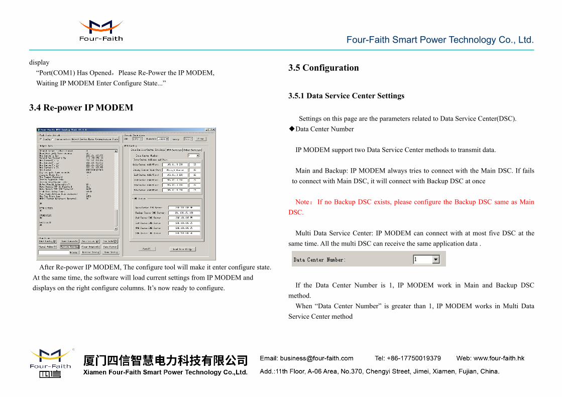
display“Port(COM1) Has Opened,Please Re-Power the IP MODEM,Waiting IP MODEM Enter Configure State...”
3.4 Re-power IPMODEM
After Re-power IP MODEM, The configure tool will make it enter configure state.At the same time, the software will load current settings from IP MODEM anddisplays on the right configure columns. It’s now ready to configure.
3.5 Configuration
3.5.1 Data Service Center Settings
Settings on this page are the parameters related to Data Service Center(DSC).◆Data Center Number
IP MODEM support two Data Service Center methods to transmit data.
Main and Backup: IP MODEM always tries to connect with the Main DSC. If failsto connect with Main DSC, it will connect with Backup DSC at once
Note: If no Backup DSC exists, please configure the Backup DSC same as MainDSC.
Multi Data Service Center: IP MODEM can connect with at most five DSC at thesame time. All the multi DSC can receive the same application data .
If the Data Center Number is 1, IP MODEM work in Main and Backup DSCmethod.When “Data Center Number” is greater than 1, IP MODEM works in Multi Data
Service Center method
Four-Faith Smart Power Technology Co., Ltd.
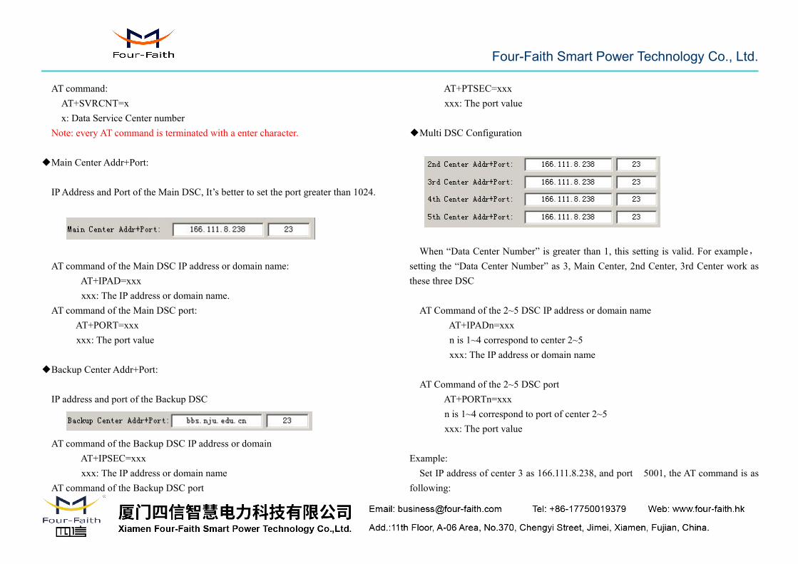
AT command:AT+SVRCNT=xx: Data Service Center number
Note: every AT command is terminated with a enter character.
◆Main Center Addr+Port:
IPAddress and Port of the Main DSC, It’s better to set the port greater than 1024.
AT command of the Main DSC IP address or domain name:AT+IPAD=xxxxxx: The IP address or domain name.
AT command of the Main DSC port:AT+PORT=xxxxxx: The port value
◆Backup Center Addr+Port:
IP address and port of the Backup DSC
AT command of the Backup DSC IP address or domainAT+IPSEC=xxxxxx: The IP address or domain name
AT command of the Backup DSC port
AT+PTSEC=xxxxxx: The port value
◆Multi DSC Configuration
When “Data Center Number” is greater than 1, this setting is valid. For example,setting the “Data Center Number” as 3, Main Center, 2nd Center, 3rd Center work asthese three DSC
AT Command of the 2~5 DSC IP address or domain nameAT+IPADn=xxxn is 1~4 correspond to center 2~5xxx: The IP address or domain name
AT Command of the 2~5 DSC portAT+PORTn=xxxn is 1~4 correspond to port of center 2~5xxx: The port value
Example:Set IP address of center 3 as 166.111.8.238, and port 5001, the AT command is as
following:
Four-Faith Smart Power Technology Co., Ltd.
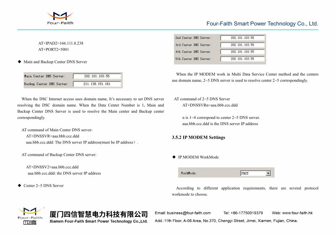
AT+IPAD2=166.111.8.238AT+PORT2=5001
◆ Main and Backup Center DNS Server
When the DSC Internet access uses domain name, It’s necessary to set DNS serverresolving the DSC domain name. When the Data Center Number is 1, Main andBackup Center DNS Server is used to resolve the Main center and Backup centercorrespondingly.
AT command of Main Center DNS server:AT+DNSSVR=aaa.bbb.ccc.dddaaa.bbb.ccc.ddd: The DNS server IP address(must be IP address).
AT command of Backup Center DNS server:
AT+DNSSV2=aaa.bbb.ccc.dddaaa.bbb.ccc.ddd: the DNS server IP address
◆ Center 2~5 DNS Server
When the IP MODEM work in Multi Data Service Center method and the centersuse domain name, 2~5 DNS server is used to resolve center 2~5 correspondingly.
AT command of 2~5 DNS ServerAT+DNSSVRn=aaa.bbb.ccc.ddd
n is 1~4 correspond to center 2~5 DNS server.aaa.bbb.ccc.ddd is the DNS server IP address
3.5.2 IPMODEM Settings
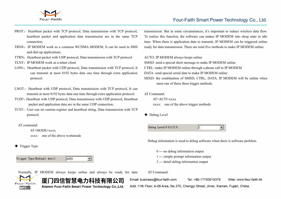
◆ IP MODEMWorkMode
According to different application requirements, there are several protocolworkmode to choose.
Four-Faith Smart Power Technology Co., Ltd.
PROT:Heartbeat packet with TCP protocol, Data transmission with TCP protocol,heartbeat packet and application data transmission are in the same TCPconnection.
TRNS:IP MODEM work as a common WCDMA MODEM, It can be used in SMSand dial-up applications.
TTRN:Heartbeat packet with UDP protocol, Data transmission with TCP protocolTLNT:IP MODEM work as a telnet clientLONG:Heartbeat packet with UDP protocol, Data transmission with TCP protocol, It
can transmit at most 8192 bytes data one time through extra applicationprotocol.
LNGT:Heartbeat with UDP protocol, Data transmission with TCP protocol, It cantransmit at most 8192 bytes data one time through extra application protocol.
TUDP:Heartbeat with UDP protocol, Data transmission with UDP protocol, Heartbeatpacket and application data are in the same UDP connection.
TCST:User can set custom register and heartbeat string, Data transmission with TCPprotocol.
AT command:AT+MODE=xxxxxxxx: one of the above workmode
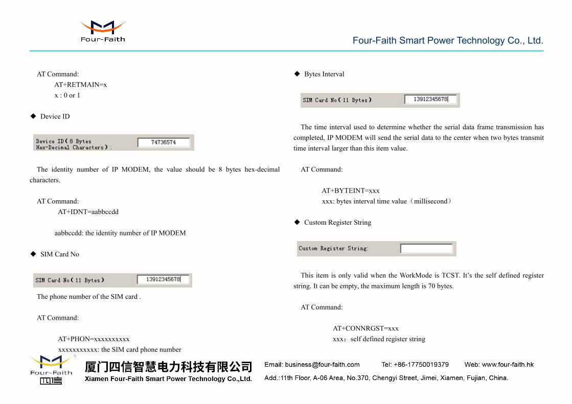
◆ Trigger Type
Normally, IP MODEM always keeps online and always be ready for data
transmission. But in some circumstances, it’s important to reduce wireless data flow.To realize this function, the software can makes IP MODEM into sleep state in idletime. When there is application data to transmit, IP MODEM can be triggered onlineready for data transmission. There are total five methods to make IP MODEM online:
AUTO: IP MODEM always keeps onlineSMSD: send a special short message to make IP MODEM onlineCTRL: make IP MODEM online through a phone call to IP MODEMDATA: send special serial data to make IP MODEM onlineMIXD: the combination of SMSD, CTRL, DATA. IP MODEM will be online when
meet one of these three trigger methods.
AT Command:AT+ACTI=xxxxxxxx: one of the above trigger methods
◆ Debug Level
Debug information is used to debug software when there is software problem.
0 --- no debug information output1 --- simple prompt information output2 --- detail debug information output
AT Command:

Four-Faith Smart Power Technology Co., Ltd.
AT+DEBUG=xx : the debug level value
Note: Only there is some problem to the IP MODEM, It’s necessary to set thisvalue as 2, In normal applications, this value should set to 0 or 1, thedefault value is 1.
◆ Databit, Parity, Stopbit
8N1 --- 8 Databit, No parity, 1 Stopbit8E1 --- 8 Databit, Even parity, 1 Stopbit8O1 --- 8 Databit, Odd parity, 1 Stopbit
AT Command:
AT+SERMODE=xxxxxx: one of the above serial mode
◆ Communication Baudrate
110 --- 110 bps300 --- 300 bps
600 --- 600 bps1200 --- 1200 bps2400 --- 2400 bps4800 --- 4800 bps9600 --- 9600 bps14400 --- 14400 bps19200 --- 19200 bps38400 --- 38400 bps56000 --- 56000 bps57600 --- 57600 bps115200 --- 115200 bps
AT Command:AT+IPR=xxx
xxx : one of the above baudrate
◆ Auto Back To Main Server
0 --- No1 ---Yes
This item is only valid when you set “Data Center Number” as 1. In this mode, IPMODEM will switch to backup center when main center have problems. If this item isset to 1 , IP MODEM will check whether the main center work fine timely. When itdetects the main server work fine, it will return back to the main server at once.
Four-Faith Smart Power Technology Co., Ltd.
AT Command:AT+RETMAIN=xx : 0 or 1
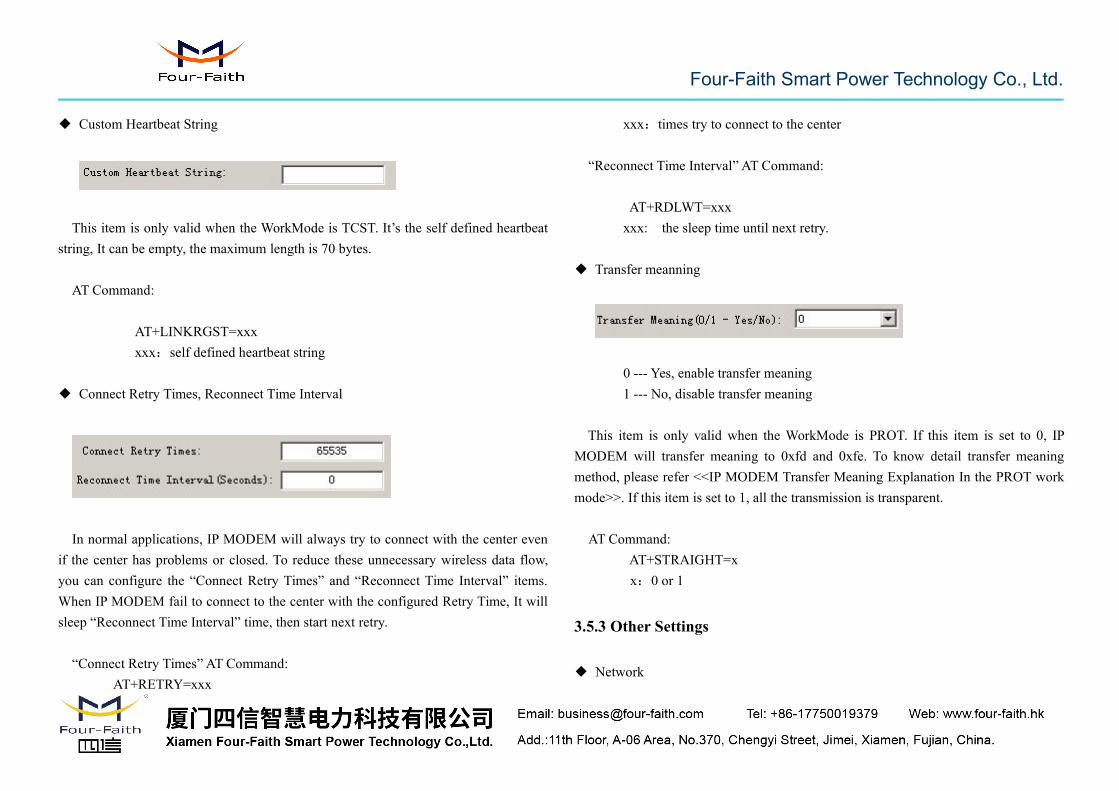
◆ Device ID
The identity number of IP MODEM, the value should be 8 bytes hex-decimalcharacters.
AT Command:AT+IDNT=aabbccdd
aabbccdd: the identity number of IP MODEM
◆ SIM Card No
The phone number of the SIM card .
AT Command:
AT+PHON=xxxxxxxxxxxxxxxxxxxxx: the SIM card phone number
◆ Bytes Interval
The time interval used to determine whether the serial data frame transmission hascompleted, IP MODEM will send the serial data to the center when two bytes transmittime interval larger than this item value.
AT Command:
AT+BYTEINT=xxxxxx: bytes interval time value(millisecond)
◆ Custom Register String
This item is only valid when the WorkMode is TCST. It’s the self defined registerstring. It can be empty, the maximum length is 70 bytes.
AT Command:
AT+CONNRGST=xxxxxx:self defined register string
Four-Faith Smart Power Technology Co., Ltd.
◆ Custom Heartbeat String
This item is only valid when the WorkMode is TCST. It’s the self defined heartbeatstring, It can be empty, the maximum length is 70 bytes.
AT Command:
AT+LINKRGST=xxxxxx:self defined heartbeat string
◆ Connect Retry Times, Reconnect Time Interval
In normal applications, IP MODEM will always try to connect with the center evenif the center has problems or closed. To reduce these unnecessary wireless data flow,you can configure the “Connect Retry Times” and “Reconnect Time Interval” items.When IP MODEM fail to connect to the center with the configured Retry Time, It willsleep “Reconnect Time Interval” time, then start next retry.
“Connect Retry Times” AT Command:AT+RETRY=xxx
xxx:times try to connect to the center
“Reconnect Time Interval” AT Command:
AT+RDLWT=xxxxxx: the sleep time until next retry.
◆ Transfer meanning
0 --- Yes, enable transfer meaning1 --- No, disable transfer meaning
This item is only valid when the WorkMode is PROT. If this item is set to 0, IPMODEM will transfer meaning to 0xfd and 0xfe. To know detail transfer meaningmethod, please refer <<IP MODEM Transfer Meaning Explanation In the PROT workmode>>. If this item is set to 1, all the transmission is transparent.
AT Command:AT+STRAIGHT=xx:0 or 1
3.5.3 Other Settings
◆ Network
Four-Faith Smart Power Technology Co., Ltd.
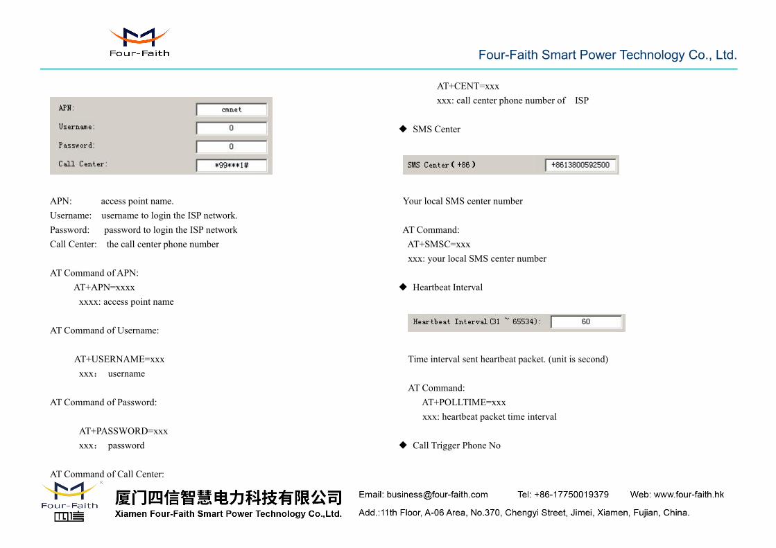
APN: access point name.Username: username to login the ISP network.Password: password to login the ISP networkCall Center: the call center phone number
AT Command of APN:AT+APN=xxxxxxxx: access point name
AT Command of Username:
AT+USERNAME=xxxxxx: username
AT Command of Password:
AT+PASSWORD=xxxxxx: password
AT Command of Call Center:
AT+CENT=xxxxxx: call center phone number of ISP
◆ SMS Center
Your local SMS center number
AT Command:AT+SMSC=xxxxxx: your local SMS center number
◆ Heartbeat Interval
Time interval sent heartbeat packet. (unit is second)
AT Command:AT+POLLTIME=xxxxxx: heartbeat packet time interval
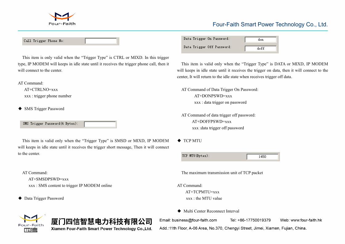
◆ Call Trigger Phone No
Four-Faith Smart Power Technology Co., Ltd.
This item is only valid when the “Trigger Type” is CTRL or MIXD. In this triggertype, IP MODEM will keeps in idle state until it receives the trigger phone call, then itwill connect to the center.
AT Command:AT+CTRLNO=xxxxxx : trigger phone number
◆ SMS Trigger Password
This item is valid only when the “Trigger Type” is SMSD or MIXD, IP MODEMwill keeps in idle state until it receives the trigger short message, Then it will connectto the center.
AT Command:AT+SMSDPSWD=xxxxxx : SMS content to trigger IP MODEM online
◆ Data Trigger Password
This item is valid only when the “Trigger Type” is DATA or MIXD, IP MODEMwill keeps in idle state until it receives the trigger on data, then it will connect to thecenter, It will return to the idle state when receives trigger off data.
AT Command of Data Trigger On Password:AT+DONPSWD=xxxxxx : data trigger on password
AT Command of data trigger off password:AT+DOFFPSWD=xxxxxx :data trigger off password
◆ TCP MTU
The maximum transmission unit of TCP packet
AT Command:AT+TCPMTU=xxxxxx : the MTU value
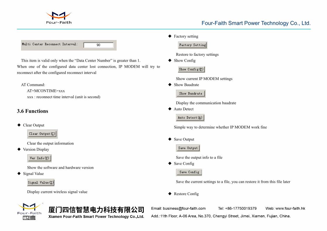
◆ Multi Center Reconnect Interval
Four-Faith Smart Power Technology Co., Ltd.
This item is valid only when the “Data Center Number” is greater than 1.When one of the configured data center lost connection, IP MODEM will try toreconnect after the configured reconnect interval
AT Command:AT+MCONTIME=xxxxxx : reconnect time interval (unit is second)
3.6 Functions
◆ Clear Output
Clear the output information◆ Version Display
Show the software and hardware version◆ Signal Value
Display current wireless signal value
◆ Factory setting
Restore to factory settings◆ Show Config
Show current IP MODEM settings◆ Show Baudrate
Display the communication baudrate◆ Auto Detect
Simple way to determine whether IP MODEM work fine
◆ Save Output
Save the output info to a file◆ Save Config
Save the current settings to a file, you can restore it from this file later
◆ Restore Config
Four-Faith Smart Power Technology Co., Ltd.
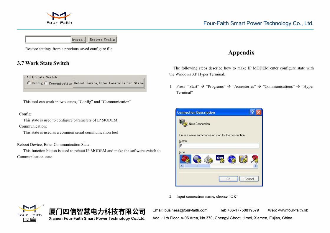
Restore settings from a previous saved configure file
3.7 Work State Switch
This tool can work in two states, “Config” and “Communication”
Config:This state is used to configure parameters of IP MODEM.
Communication:This state is used as a common serial communication tool
Reboot Device, Enter Communication State:This function button is used to reboot IP MODEM and make the software switch to
Communication state
Appendix
The following steps describe how to make IP MODEM enter configure state withthe Windows XP Hyper Terminal.
1. Press “Start” ”Programs” ”Accessories” ”Communications” ”HyperTerminal”
2. Input connection name, choose “OK”
Four-Faith Smart Power Technology Co., Ltd.
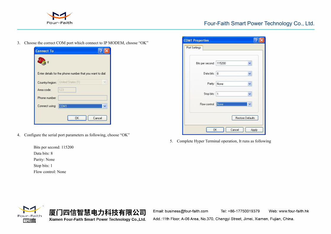
3. Choose the correct COM port which connect to IP MODEM, choose “OK”
4. Configure the serial port parameters as following, choose “OK”
Bits per second: 115200Data bits: 8Parity: NoneStop bits: 1Flow control: None
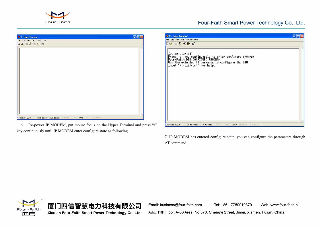
5. Complete Hyper Terminal operation, It runs as following
Four-Faith Smart Power Technology Co., Ltd.
6. Re-power IP MODEM, put mouse focus on the Hyper Terminal and press “s”key continuously until IP MODEM enter configure state as following
7. IP MODEM has entered configure state, you can configure the parameters throughAT command.


