C ATA L O GThe Safety Va l v e
API Seri e sAPI Seri e s
Series 526
Folder API Series 526 NEW 7/13/04 4:37 PM Page 1
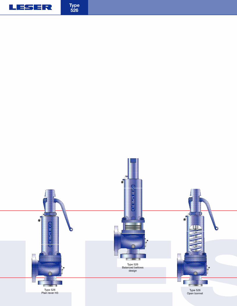
Type 526
Type 526Plain lever H3
Type 526Open bonnet
Type 526Balanced bellows
design
Folder API Series 526 NEW 7/13/04 4:37 PM Page 2
LWN 470.01
Flanged Safety Relief Valves · API Series Contents
3
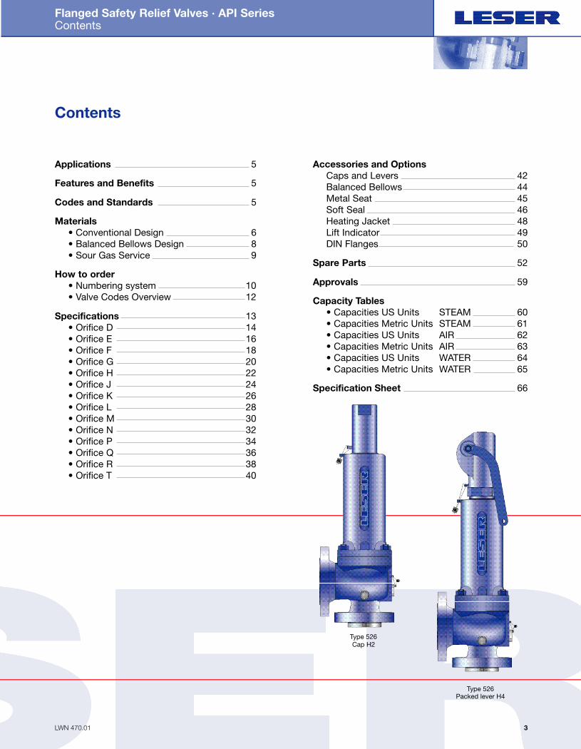
Contents
Accessories and OptionsCaps and Levers 42Balanced Bellows 44Metal Seat 45Soft Seal 46Heating Jacket 48Lift Indicator 49DIN Flanges 50
Spare Parts 52
Approvals 59
Capacity Tables• Capacities US Units STEAM 60• Capacities Metric Units STEAM 61• Capacities US Units AIR 62• Capacities Metric Units AIR 63• Capacities US Units WATER 64• Capacities Metric Units WATER 65
Specification Sheet 66
Applications 5
Features and Benefits 5
Codes and Standards 5
Materials • Conventional Design 6• Balanced Bellows Design 8• Sour Gas Service 9
How to order • Numbering system 10• Valve Codes Overview 12
Specifications 13• Orifice D 14• Orifice E 16• Orifice F 18• Orifice G 20• Orifice H 22• Orifice J 24• Orifice K 26• Orifice L 28• Orifice M 30• Orifice N 32• Orifice P 34• Orifice Q 36• Orifice R 38• Orifice T 40
Type 526Cap H2
Type 526Packed lever H4
Folder API Series 526 NEW 7/13/04 4:37 PM Page 3

LWN 470.02
Flanged Safety Relief Valves · API Series Type 526
4
LESER´s API series 526 is a
spring loaded pressure relief valve
series, specially designed and manu-
factured to API 526 and approved
according to ASME (Sec. VIII, Div. 1)
the Canadian CRN, the European PED
standard, the German AD 2000-Merk-
blatt A2 and those of many other
countries, covering requirements from
end-users, OEM´ s and engineering
companies worldwide, thus allowing
immediate replacement.
LESER´s API series 526 has
been optimized in close cooperation
with plant engineers and service spe-
cialists, simplifying design with fewer
components for less down time, fewer
spare parts and lower maintenance
costs.
Extensive testing at the LESER
ASME-certified test lab together with
up to date manufacturing processes
ensure the reliability of this state of
the art product.
Folder API Series 526 NEW 7/13/04 4:37 PM Page 4
LWN 470.03
Flanged Safety Relief Valves · API Series Applications · Features and Benefits · Codes and Standards
5
Applications
LESER´s API series 526 presents thesimple safe solution for heavy dutyapplications, such as crude oil extrac-tion, transportation and processing in● Refineries● Chemical industry● Petrochemical industry● Oil and Gas - Onshore and Offshore● Oilfields (“Christmas trees”)● Vessels & piping systems● Blow-down systems● Storage tank farms
Features and Benefits
LESER´s API series 526 covers a largevariety of types, materials and optionsto fit any application:
Scope of Design● Seven valve sizes from 1” through 8”● 14 orifice sizes from D through T● Materials: WCB, WC6, CF8M and a
wide range of material variations forcritical applications
● Open or closed bonnet, packed orplain lifting lever or gastight cap
● Optional balanced bellows con-struction for back pressure compen-sation
● Heating jacket available for high vis-cosity fluids
● Many other options to adjust to var-ious operating conditions
Simplified design for “built-in safety”● Fool-proof design with few parts for
built-in safety● Single trim for steam, gas and liquid
for fewer spare parts and easiermaintenance
● One-piece spindle reduces friction ● Two-point-guided nozzle for im-
proved alignment● Self draining body avoids residues
and reduces corrosion● Long springs for large pre s s u re
ranges
Ease of plant design, installation,operation and maintenance ● Reduced number of components for
easier and more cost effective main-tenance
● Replaceable nozzle and disc● Stellited or hardened metal sealing
for longer product life● Optional soft seat for superior tight-
ness● Integral cast support brackets
Codes and Standards
LESER´s API series 526 complies withthe following codes and standards:● ASME Section VIII – National Board
certified capacities (single trim forsteam, gas and liquid service): UV-stamp
● ASME Section II - materials● ASME B16.34 and ASME B16.5 -
flanging● API 526 – fourth edition 1995● API 520 and 527● NACE MR 0175● ISO 4126● PED 97/23 / EC (CE-marking)● CRN, VdTUEV-SV 100,
AD 2000-Merkblatt A2● Others
Folder API Series 526 NEW 7/13/04 4:37 PM Page 5
LWN 470.04
Flanged Safety Relief Valves · API Series Materials – Conventional Design
Type 526
6
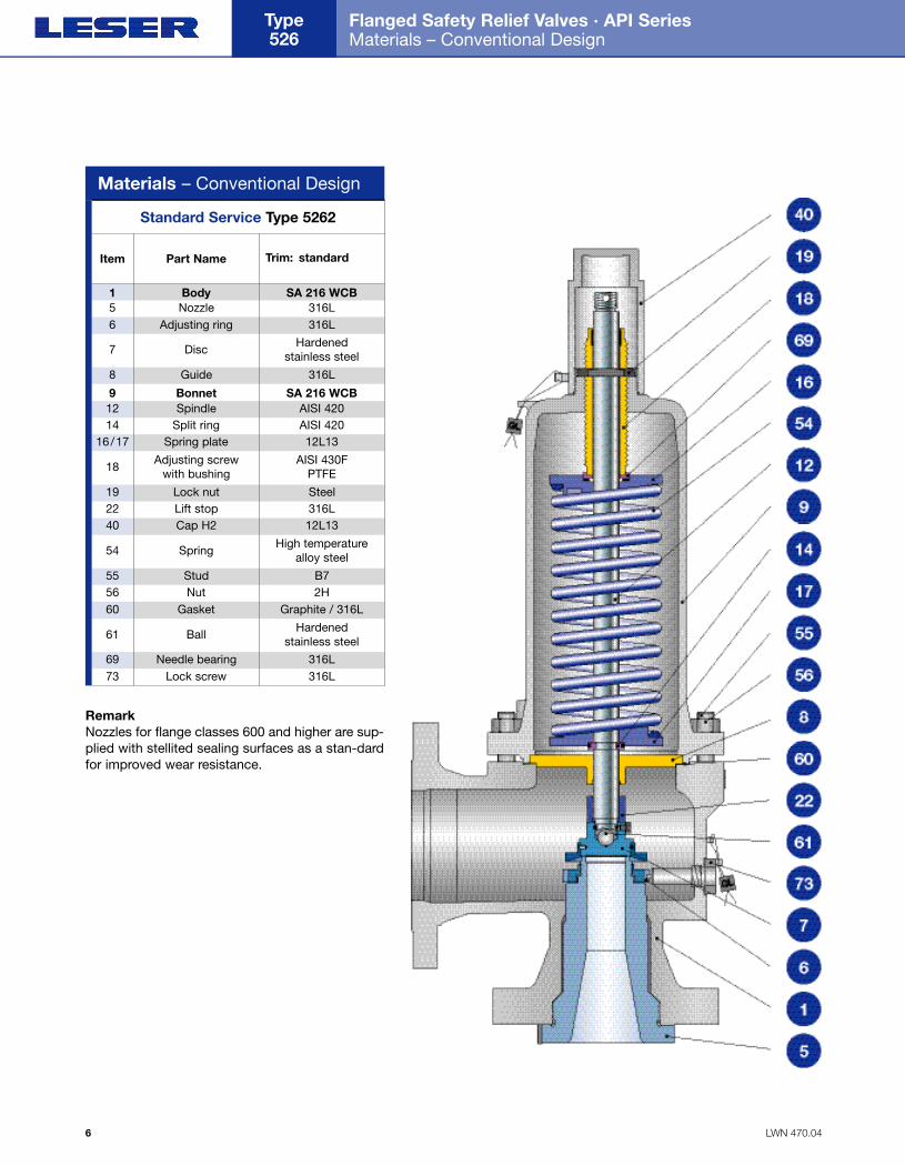
Materials – Conventional Design
Item Part Name Trim: standard
Standard Service Type 5262
1 Body SA 216 WCB5 Nozzle 316L6 Adjusting ring 316L
7 Disc Hardenedstainless steel
8 Guide 316L
9 Bonnet SA 216 WCB12 Spindle AISI 42014 Split ring AISI 420
16/17 Spring plate 12L13
18 Adjusting screw with bushing
AISI 430FPTFE
19 Lock nut Steel22 Lift stop 316L
54 Spring High temperaturealloy steel
40 Cap H2 12L13
55 Stud B756 Nut 2H60 Gasket Graphite / 316L
61 Ball Hardenedstainless steel
69 Needle bearing 316L73 Lock screw 316L
RemarkNozzles for flange classes 600 and higher are sup-plied with stellited sealing surfaces as a stan-dardfor improved wear resistance.
Folder API Series 526 NEW 7/13/04 4:37 PM Page 6
LWN 470.05 7
Flanged Safety Relief Valves · API Series Material Options – Conventional Design
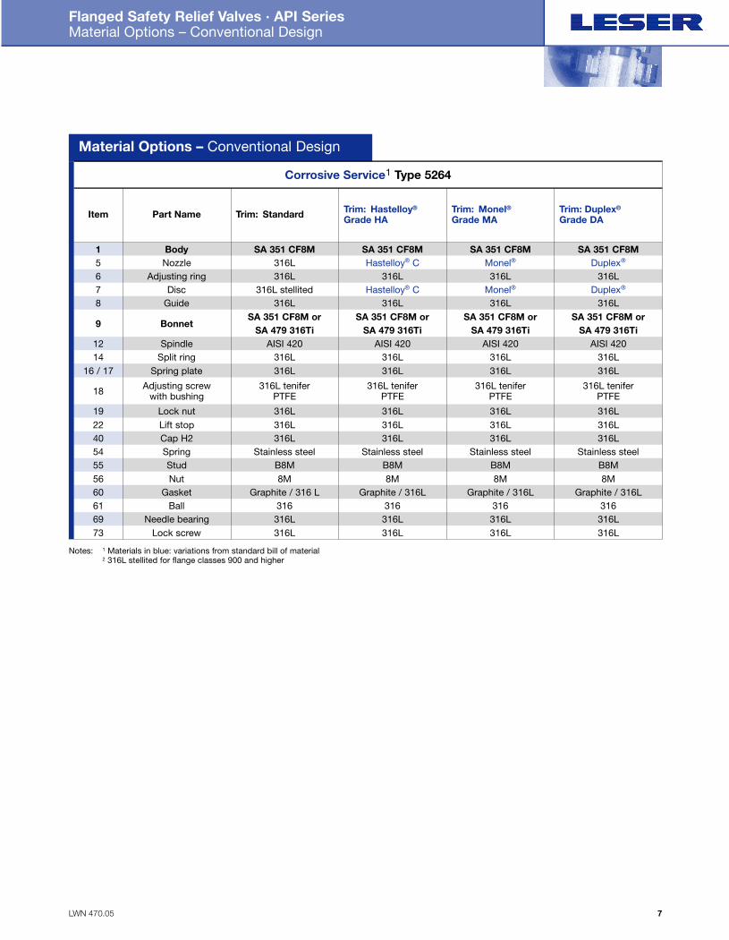
Material Options – Conventional Design
Corrosive Service1 Type 5264
Trim: Duplex®
Grade DATrim: Monel®Grade MA
Trim: Hastelloy®
Grade HATrim: StandardPart NameItem
SA 351 CF8MSA 351 CF8MSA 351 CF8MSA 351 CF8MBody1Duplex®Monel®Hastelloy® C316LNozzle5
Duplex®Monel®Hastelloy® C316L stellitedDisc7316L316L316L316LAdjusting ring6
316L316L316L316LGuide8SA 351 CF8M orSA 351 CF8M orSA 351 CF8M orSA 351 CF8M or
Bonnet9
Spindle12SA 479 316TiSA 479 316TiSA 479 316TiSA 479 316Ti
AISI 420AISI 420AISI 420AISI 420
Spring plate16 / 17 316L316L316L316LSplit ring14 316L316L316L316L
Adjusting screw with bushing18 316L tenifer
PTFE316L tenifer
PTFE316L tenifer
PTFE316L tenifer
PTFE
Cap H24054
316L316L316L316LLift stop22 316L316L316L316LLock nut19 316L316L316L316L
Spring Stainless steelStainless steelStainless steelStainless steel55 Stud B8MB8MB8MB8M56 Nut 8M8M8M8M60 Gasket Graphite / 316LGraphite / 316LGraphite / 316LGraphite / 316 L61 Ball 31631631631669 Needle bearing 316L316L316L316L73 Lock screw 316L316L316L316L
Notes: 1 Materials in blue: variations from standard bill of material2 316L stellited for flange classes 900 and higher
Folder API Series 526 NEW 7/13/04 4:37 PM Page 7
Flanged Safety Relief Valves · API Series Materials – Balanced Bellows Design
Type 526
8 LWN 470.06
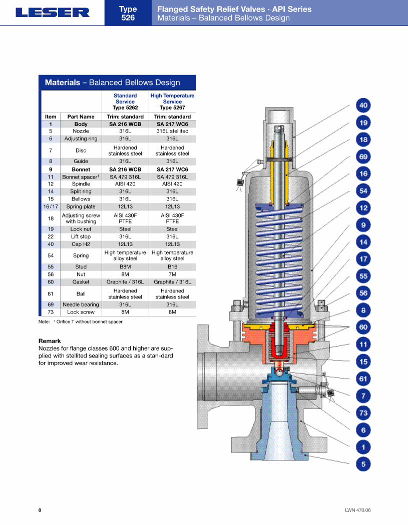
Materials – Balanced Bellows Design
Item Part Name Trim: standard
StandardService
Type 5262
Trim: standard
High Te m p e r a t u reService
Type 5267
1 Body SA 216 WCB SA 217 WC65 Nozzle 316L 316L stellited6 Adjusting ring 316L 316L
7 Disc Hardened stainless steel
Hardened stainless steel
8 Guide 316L 316L
9 Bonnet SA 216 WCB SA 217 WC611 Bonnet spacer1 SA 479 316L SA 479 316L
14 Split ring 316L 316L12 Spindle AISI 420 AISI 420
15 Bellows 316L 316L16/17 Spring plate 12L13 12L13
18 Adjusting screw with bushing
AISI 430FPTFE
AISI 430FPTFE
54 Spring High temperaturealloy steel
High temperaturealloy steel
40 Cap H2 12L13 12L13
19 Lock nut Steel Steel22 Lift stop 316L 316L
55 Stud B8M B1656 Nut 8M 7M60 Gasket Graphite / 316L Graphite / 316L
61 Ball Hardened stainless steel
Hardened stainless steel
69 Needle bearing 316L 316L73 Lock screw 8M 8M
Note: 1 Orifice T without bonnet spacer
RemarkNozzles for flange classes 600 and higher are sup-plied with stellited sealing surfaces as a stan-dardfor improved wear resistance.
Folder API Series 526 NEW 7/13/04 4:37 PM Page 8
LWN 470.07
Flanged Safety Relief Valves · API Series Material Options – Balanced Bellows Design · Sour Gas Service (H2S)
9
18
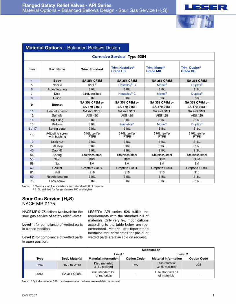
Material Options – Balanced Bellows Design
Corrosive Service1 Type 5264
Trim: Duplex®
Grade DBTrim: Monel®Grade MB
Trim: Hastelloy®
Grade HBTrim: StandardPart NameItem
SA 351 CF8MSA 351 CF8MSA 351 CF8MSA 351 CF8MBody1Duplex®Monel®Hastelloy® C316L2Nozzle5
Duplex®Monel®Hastelloy® C316L stellitedDisc7316L316L316L316LAdjusting ring6
316L316L316L316LGuide8SA 351 CF8M orSA 351 CF8M orSA 351 CF8M orSA 351 CF8M or
Bonnet9
Spindle12
SA 479 316TiSA 479 316TiSA 479 316TiSA 479 316Ti
AISI 420AISI 420AISI 420AISI 420Bonnet spacer11 SA 479 316LSA 479 316LSA 479 316LSA 479 316L
Spring plate16 / 17
22
316L316L316L316LBellows15 Duplex®Monel®Hastelloy®316LSplit ring14 316L316L316L316L
Adjusting screw with bushing
316L teniferPTFE
316L teniferPTFE
316L teniferPTFE
316L teniferPTFE
Cap H24054
316L316L316L316LLift stop 316L316L316L316L
19 Lock nut 316L316L316L316L
Spring Stainless steelStainless steelStainless steelStainless steel55 Stud B8MB8MB8MB8M56 Nut 8M8M8M8M60 Gasket Graphite / 316LGraphite / 316LGraphite / 316LGraphite / 316L61 Ball 3 1 63 1 63 1 63 1 669 Needle bearing 316L316L316L316L73 Lock screw 316L316L316L316L
Sour Gas Service (H2S)NACE MR 0175
NACE MR 0175 defines two levels for thesour gas service of safety relief valves:
Level 1: for compliance of wetted partsin closed position
Level 2: for compliance of wetted partsin open position.
L E S E R’s API series 526 fulfills therequirements with the standard bill ofmaterials. Only very few modificationsaccording to the table below are rec-ommended. Material test reports andhardness test certificates for pro-ductwetted parts are available on request.
Option CodeBody Material
Modification
Option Code
SA 216 WCB
SA 351 CF8M
Type
5262
5264
J25
–
Material InformationDisc material: 316L stellited
Use standard bill of materials
J25
–
Material InformationLevel 1 Level 2
Disc material: 316L stellited1
Use standard bill of materials1
Note: 1 Spindle material 316L or stainless steel bellows are available on request.
Notes: 1 Materials in blue: variations from standard bill of material2 316L stellited for flange classes 900 and higher
Folder API Series 526 NEW 7/13/04 4:37 PM Page 9
LWN 470.08
Flanged Safety Relief Valves · API Series How to Order – Numbering System
Type 526
10
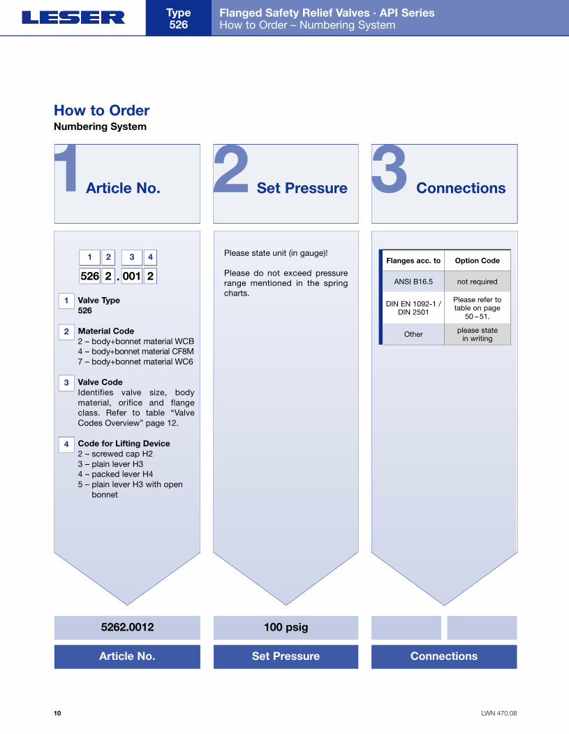
5262.0012 100 psig
Article No. Set Pressure Connections
1 2 3
. Valve Type 526
. Material Code2 – body+bonnet material WCB4 – body+bonnet material CF8M7 – body+bonnet material WC6
. Valve CodeIdentifies valve size, bodymaterial, orifice and flange class. Refer to table “Va l v eCodes Overview” page 12.
. Code for Lifting Device2 – screwed cap H23 – plain lever H34 – packed lever H45 – plain lever H3 with open
bonnet
Please state unit (in gauge)!
Please do not exceed pressurerange mentioned in the springcharts.
Flanges acc. to Option Code
ANSI B16.5 not required
DIN EN 1092-1 /DIN 2501
Please refer totable on page
50 – 51.
Other please state in writing
Article No. Set Pressure Connections
526 2 001 2
1 2
1
2
3
4
3 4
.
How to OrderNumbering System
Folder API Series 526 NEW 7/13/04 4:38 PM Page 10
LWN 470.09
Flanged Safety Relief Valves · API Series How to Order – Numbering System
11
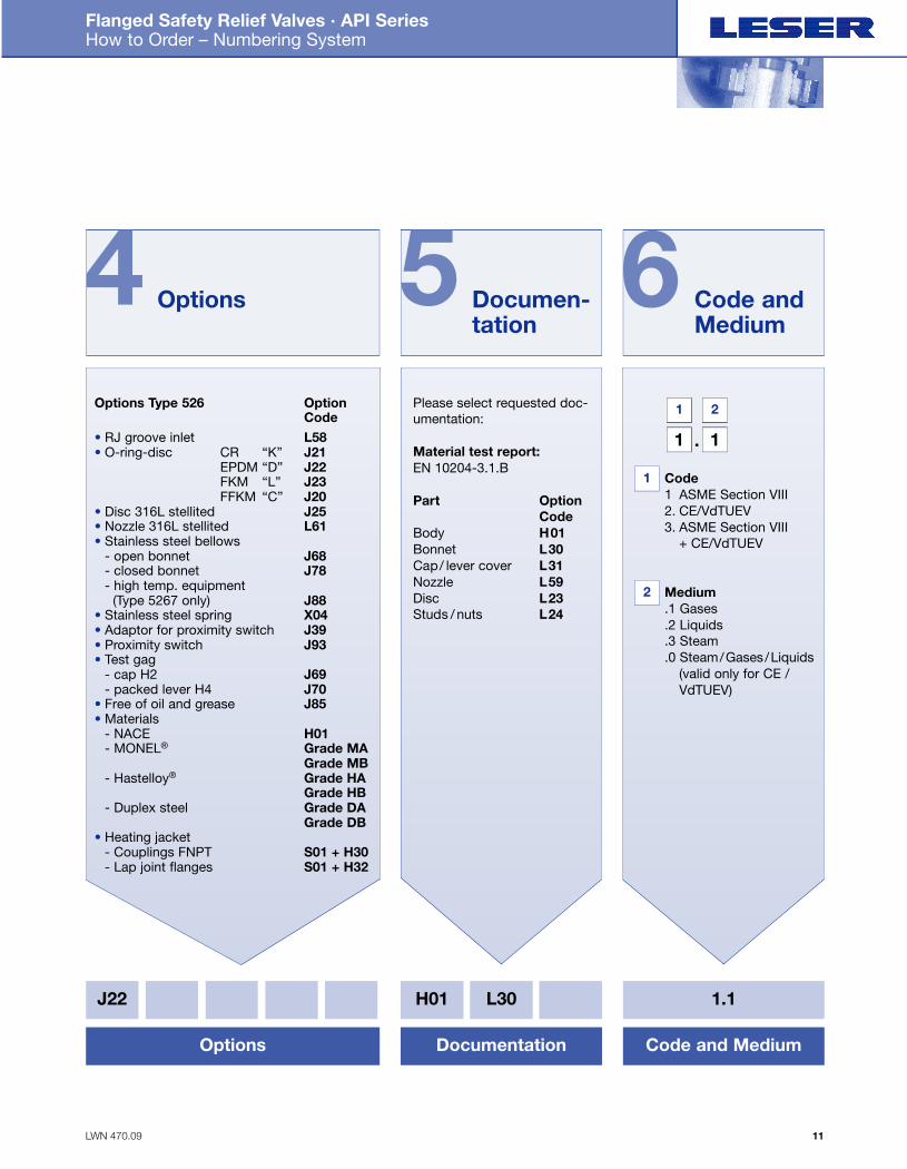
4 5 6Options Type 526 Option
Code• RJ groove inlet L58• O-ring-disc CR “K” J21
EPDM “D” J22FKM “L” J23FFKM “C” J20
• Disc 316L stellited J25• Nozzle 316L stellited L61• Stainless steel bellows
- open bonnet J68- closed bonnet J78- high temp. equipment
(Type 5267 only) J88• Stainless steel spring X04• Adaptor for proximity switch J39• Proximity switch J93• Test gag
- cap H2 J69- packed lever H4 J70
• Free of oil and grease J85• Materials
- NACE H01- MONEL® Grade MA
Grade MB- Hastelloy® Grade HA
Grade HB- Duplex steel Grade DA
Grade DB• Heating jacket
- Couplings FNPT S01 + H30- Lap joint flanges S01 + H32
Please select requested doc-umentation:
Material test report:EN 10204-3.1.B
Part Option Code
Body H01Bonnet L30Cap/ lever cover L31Nozzle L59Disc L23Studs / nuts L24
. Code 1 ASME Section VIII2. CE/VdTUEV3. ASME Section VIII
+ CE/VdTUEV
. Medium .1 Gases.2 Liquids.3 Steam.0 Steam/Gases/Liquids
(valid only for CE / VdTUEV)
Options Documen-tation
Code and Medium
J22 H01 L30 1.1
Options Documentation Code and Medium
1 1
1 2
.
1
2
Folder API Series 526 NEW 7/13/04 4:38 PM Page 11

LWN 470.10
Flanged Safety Relief Valves · API Series How to order · Valve Codes Overview
Type 526
12
Valve Codes Overview
How to Order
Note: “L” in Flange Class 300L means low.Class 300 has higher pressure-temperature ratings than class 300L.
Orificeletter
Body Material
Body Material
Body Material
Orifice[Inch2]
D 0.110
1500x300900x300600x150300x150300Lx150150x150Flange Class
1” x 2”
2500x300WCB WC6 CF8M
0 0 1 – 010
1” x 2”002 – 011
1” x 2”002 006 011
1” x 2”003 007 012
1 1/2” x 2”004 008 013
1 1/2” x 3”005 009 014
E 0.1961” x 2”
0 1 5 – 024
1” x 2”016 – 025
1” x 2”016 020 025
1” x 2”017 021 026
dimensions for 1 1/2” x 2”018 022 027
1 1/2” x 3”019 023 028
F 0.3071 1/2” x 2”
0 2 9 / 039
1 1/2” x 2”030 – 040
1 1/2” x 2”031 035 041
1 1/2” x 2”032 042
these sizes 1 1/2” x 3”033 037 043
1 1/2” x 3”034 038 044
G 0.5031 1/2” x 3”
0 4 5 – 110
1 1/2” x 3”046 – 111
1 1/2” x 3”047 052 112
1 1/2” x 3”048 053 113
1 1/2” x 3”049 054 114
2” x 3”050 055 115
2” x 3”051 056 116
H 0.7851 1/2” x 3”
1 4 2 – 152
1 1/2” x 3”143 – 153
2” x 3”144 148 154
2” x 3”145 149 155
2” x 3”146 150 156
2” x 3”147 151 157
J 1.2872” x 3”
1 6 2 – 196
2” x 3”163 – 197
3” x 4”164 168 198
3” x 4”165 169 199
3” x 4”166 170 200
3” x 4”167 171 201
K 1.8383” x 4”
2 0 2 – 211
3” x 4”203 – 212
3” x 4”203 207 212
3” x 4”204 208 213
3” x 6”205 209 214
3” x 6”206 210 215
L 2.8533” x 4”
2 3 2 – 242
3” x 4”233 – 243
4” x 6”234 238 244
4” x 6”235 239 245
4” x 6”236 240 246
4” x 6”237 241 –
M 3.6004” x 6”
5 8 0 – 587
4” x 6”581 – 588
4” x 6”581 584 588
4” x 6”582 585 589
4” x 6”583 586 –
N 4.3404” x 6”
5 9 0 – 597
4” x 6”591 – 598
4” x 6”591 594 598
4” x 6”592 595 599
4” x 6”593 596 –
P 6.3804” x 6”
6 4 5 – 653
4” x 6”646 – 654
4” x 6”647 650 655
4” x 6”648 651 656
4” x 6”649 652 –
Q 11.0506” x 8”
6 5 7 – 662
6” x 8”658 – 663
6” x 8”658 660 663
6” x 8”659 661 664
R 16.0006” x 8”
6 6 5 – 671
6” x 8”666 669 672
6” x 10”667 – 673
6” x 10”668 670 674
T 26.0008” x 10”
6 7 5 – 678
8” x 10”676 – 679
8” x 10”676 677 679
Orificeletter
Orifice[Inch2]
WCB WC6 CF8M WCB WC6 CF8M WCB WC6 CF8M WCB WC6 CF8M WCB WC6 CF8M WCB WC6 CF8M
1500x300900x150600x150300x150300Lx150150x150Flange Class
Orificeletter
Orifice[Inch2] 1500x150900x150600x150300x150300Lx150150x150
Flange Class
WCB WC6 CF8M WCB WC6 CF8M WCB WC6 CF8M WCB WC6 CF8M WCB WC6 CF8M WCB WC6 CF8M
WCB WC6 CF8M WCB WC6 CF8M WCB WC6 CF8M WCB WC6 CF8M WCB WC6 CF8M WCB WC6 CF8M
Flange Class inlet x outlet
Valve size inlet x outlet
Valve Code
The valve code identifies· Valve size· Body Material· Orifice· Flange Class
Body Material
Use 1500-lb
Folder API Series 526 NEW 7/13/04 4:38 PM Page 12
LWN 470.11
Flanged Safety Relief Valves · API Series Specifications
13
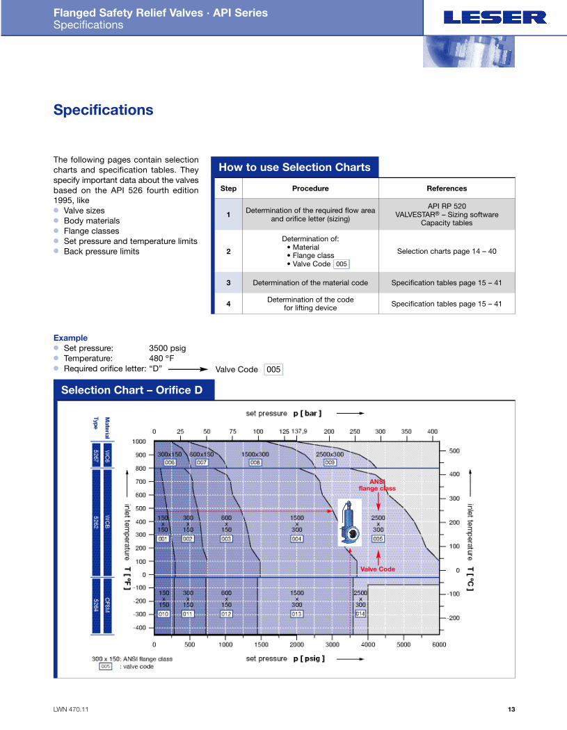
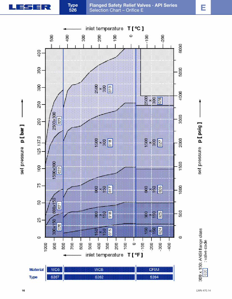
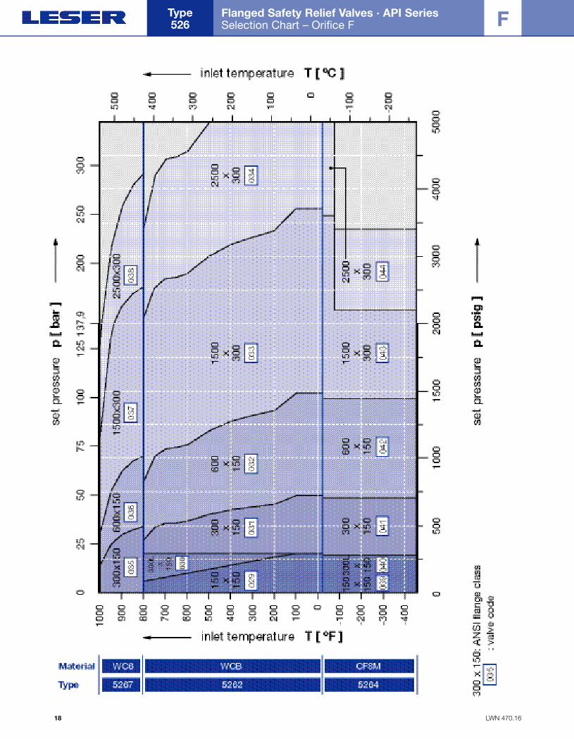
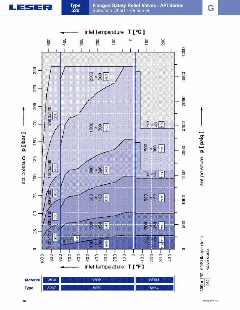
The following pages contain selectioncharts and specification tables. Theyspecify important data about the valvesbased on the API 526 fourth edition1995, like● Valve sizes● Body materials● Flange classes● Set pressure and temperature limits● Back pressure limits
Specifications
How to use Selection Charts
Step
1 Determination of the required flow areaand orifice letter (sizing)
API RP 520VALVESTAR® – Sizing software
Capacity tables
2
Determination of:• Material• Flange class• Valve Code
Selection charts page 14 – 40
3 Determination of the material code Specification tables page 15 – 41
4 Determination of the code for lifting device Specification tables page 15 – 41
Procedure References
Selection Chart – Orifice D
005
ANSI flange class
Valve Code
Example● Set pressure: 3500 psig● Temperature: 480 ºF● Required orifice letter: “D” Valve Code 005
Folder API Series 526 NEW 7/13/04 4:38 PM Page 13
LWN 470.12
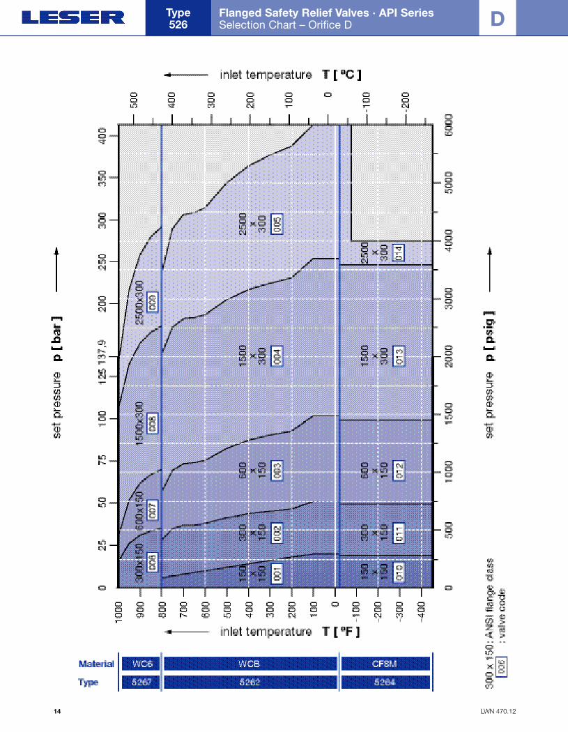
Flanged Safety Relief Valves · API Series Selection Chart – Orifice D
Type 526
14
D
Folder API Series 526 NEW 7/13/04 4:38 PM Page 14

LWN 470.13
Flanged Safety Relief Valves · API Series Specifications – Orifice D
15
D
FlangeRating Article No.
Max. set pressure[psig] Back pressure
limits [psig]ValveSize
Inlet OutletCF8M WCB WC62
150 150 5264.010■ 5262.001■ – 275 275 285 185 80 – – 285 230
CF8M WCB WC6 -76° F1 -21° F 100° F 450° F 800° F 800° F 1000° F Conv. Bellows1 D 2
300 150 5264.011■ 5262.002■ 5267.006■ 720 720 740 615 410 510 225 285 2301 D 2600 150 5264.012■ 5262.003■ 5267.007■ 1440 1440 1480 1235 825 1015 445 285 2301 D 2
1500 300 5264.013■ 5262.004■ 5267.008■ 3600 3600 3705 3080 2060 2540 1115 600 50011/2 D 22500 300 5264.014■ 5262.005■ 5267.009■ 4000 6000 6000 5135 3430 4230 1860 740 50011/2 D 3
900 300 – – – Use 1500-lb dimensions for these sizes11/2 D 2
FlangeRating Article No.
Max. set pressure[bar] Back pressure
limits [bar]ValveSize
Inlet OutletCF8M WCB WC62
150 150 5264.010■ 5262.001■ – 19.0 19.0 19.7 12.8 5.5 – – 19.7 15.9
CF8M WCB WC6 -60°C1 -29°C 38°C 232°C 427°C 427°C 538°C Conv. Bellows
1 D 2300 150 5264.011■ 5262.002■ 5267.006■ 49.6 49.6 51.0 42.4 28.3 35.2 15.5 19.7 15.91 D 2600 150 5264.012■ 5262.003■ 5267.007■ 99.3 99.3 102.0 85.1 56.9 70.0 30.6 19.7 15.91 D 2
1500 300 5264.013■ 5262.004■ 5267.008■ 248.2 248.2 255.4 212.4 142.0 175.1 76.8 41.4 34.511/2 D 22500 300 5264.014■ 5262.005■ 5267.009■ 275.8 413.7 413.7 354.0 236.5 291.6 128.2 51.0 34.511/2 D 3
900 300 – – – Use 1500-lb dimensions for these sizes11/2 D 2
Orifice D – Specification
FlangeRating
Dimensions[inch]
Bellows DesignWeight[lbs]
ValveSize
Inlet Outlet150 150 4 1/8
a Hm m
[inch] [lbs]
1 D 2300 150 4 1/81 D 2600 150 4 1/81 D 2
1500 300 4 1/811/2 D 22500 300 5 1/211/2 D 3
900 300 Use 1500-lb dimensions for these sizes
4 1/2b
4 1/24 1/2
5 1/27
1 3/16
s
1 3/16
1 3/16
1 3/4
2 1/4
13 5/32
H
13 5/32
13 5/32
16 3/16
17 3/16
5 1/8A
5 1/85 1/8
6 3/86 3/8
–
B
––
––
Ø 9/16
C
Ø 9/16
Ø 9/16
Ø 9/16
Ø 9/16
5 7/32
D
5 7/32
5 7/32
5 3/32
7 15/32
5/8 38.1 14 1/8 40.538.1 14 1/8 40.538.1 14 1/8 40.5
68.6 17 5/32 73.092.2 17 3/16 98.4
E
5/85/8
5/85/8
11/2 D 2
FlangeRating
Dimensions[mm]
Bellows DesignWeight[kg]
ValveSize
Inlet Outlet
150 150 105
a Hm m
[mm] [kg]
1 D 2300 150 1051 D 2600 150 1051 D 2
1500 300 10511/2 D 22500 300 14011/2 D 3
900 300 Use 1500-lb dimensions for these sizes
114
b
114114
140178
30
s
3030
4457
335
H
335335
412436
130
A
130130
162162
–
B
––
––
Ø 14
C
Ø 14Ø 14
Ø 14Ø 14
132
D
132132
129189
16 17.3 360 18.417.3 360 18.417.3 360 18.4
31.1 437 33.141.8 436 44.6
E
1616
1616
11/2 D 2
Conventional design Balanced bellows design
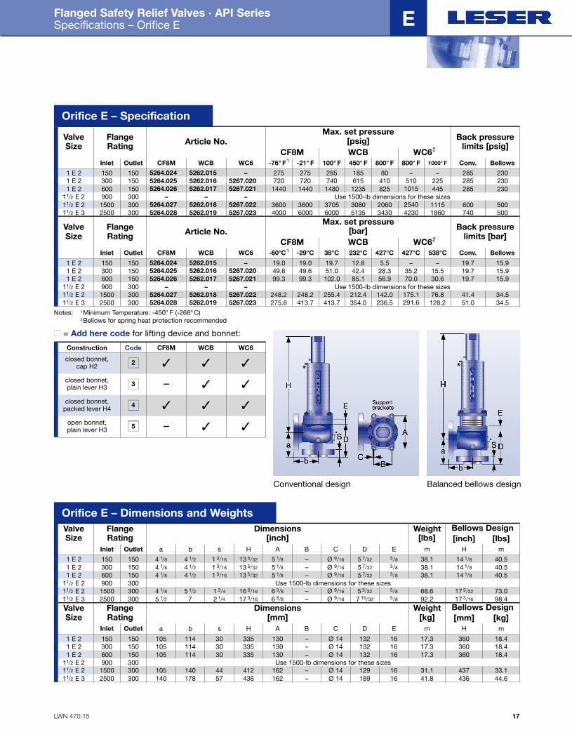
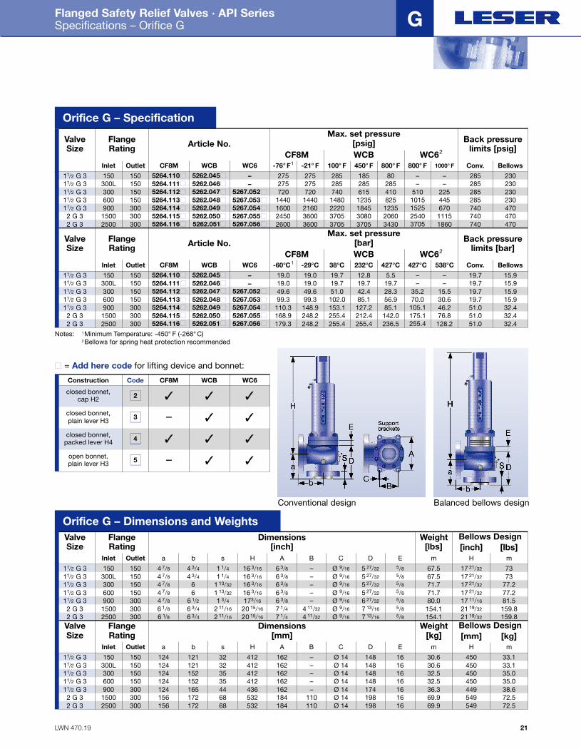
Notes: 1Minimum Temperature: -450° F (-268° C)2Bellows for spring heat protection recommended
Code CF8M WCB WC6
closed bonnet,cap H2
Construction
closed bonnet,plain lever H3
closed bonnet, packed lever H4
open bonnet, plain lever H3
2
3
4
5
✓ ✓ ✓
– ✓ ✓
✓ ✓ ✓
– ✓ ✓
■ = Add here code for lifting device and bonnet:
Orifice D – Dimensions and Weights
Folder API Series 526 NEW 7/13/04 4:38 PM Page 15
LWN 470.14
Flanged Safety Relief Valves · API Series Selection Chart – Orifice E
Type 526
16
E
Folder API Series 526 NEW 7/13/04 4:38 PM Page 16
LWN 470.15
Flanged Safety Relief Valves · API Series Specifications – Orifice E
17
E
FlangeRating Article No.
Max. set pressure[psig] Back pressure
limits [psig]ValveSize
Inlet OutletCF8M WCB WC62
150 150 5264.024■ 5262.015■ – 275 275 285 185 80 – – 285 230
CF8M WCB WC6 -76° F1 -21° F 100° F 450° F 800° F 800° F 1000° F Conv. Bellows1 E 2
300 150 5264.025■ 5262.016■ 5267.020■ 720 720 740 615 410 510 225 285 2301 E 2600 150 5264.026■ 5262.017■ 5267.021■ 1440 1440 1480 1235 825 1015 445 285 2301 E 2
1500 300 5264.027■ 5262.018■ 5267.022■ 3600 3600 3705 3080 2060 2540 1115 600 50011/2 E 22500 300 5264.028■ 5262.019■ 5267.023■ 4000 6000 6000 5135 3430 4230 1860 740 50011/2 E 3
900 300 – – – Use 1500-lb dimensions for these sizes11/2 E 2
FlangeRating Article No.
Max. set pressure[bar] Back pressure
limits [bar]ValveSize
Inlet OutletCF8M WCB WC62
150 150 5264.024■ 5262.015■ – 19.0 19.0 19.7 12.8 5.5 – – 19.7 15.9
CF8M WCB WC6 -60°C1 -29°C 38°C 232°C 427°C 427°C 538°C Conv. Bellows
1 E 2300 150 5264.025■ 5262.016■ 5267.020■ 49.6 49.6 51.0 42.4 28.3 35.2 15.5 19.7 15.91 E 2600 150 5264.026■ 5262.017■ 5267.021■ 99.3 99.3 102.0 85.1 56.9 70.0 30.6 19.7 15.91 E 2
1500 300 5264.027■ 5262.018■ 5267.022■ 248.2 248.2 255.4 212.4 142.0 175.1 76.8 41.4 34.511/2 E 22500 300 5264.028■ 5262.019■ 5267.023■ 275.8 413.7 413.7 354.0 236.5 291.6 128.2 51.0 34.511/2 E 3
900 300 – – – Use 1500-lb dimensions for these sizes11/2 E 2
Orifice E – Specification
FlangeRating
Dimensions[inch]
Bellows DesignWeight[lbs]
ValveSize
Inlet Outlet150 150 4 1/8
a Hm m
[inch] [lbs]
1 E 2300 150 4 1/81 E 2600 150 4 1/81 E 2
1500 300 4 1/811/2 E 22500 300 5 1/211/2 E 3
900 300 Use 1500-lb dimensions for these sizes
4 1/2b
4 1/24 1/2
5 1/27
1 3/16
s
1 3/16
1 3/16
1 3/4
2 1/4
13 5/32
H
13 5/32
13 5/32
16 3/16
17 3/16
5 1/8A
5 1/85 1/8
6 3/86 3/8
–
B
––
––
Ø 9/16
C
Ø 9/16
Ø 9/16
Ø 9/16
Ø 9/16
5 7/32
D
5 7/32
5 7/32
5 3/32
7 15/32
5/8 38.1 14 1/8 40.538.1 14 1/8 40.538.1 14 1/8 40.5
68.6 17 5/32 73.092.2 17 3/16 98.4
E
5/85/8
5/85/8
11/2 E 2
FlangeRating
Dimensions[mm]
Bellows DesignWeight[kg]
ValveSize
Inlet Outlet
150 150 105
a Hm m
[mm] [kg]
1 E 2300 150 1051 E 2600 150 1051 E 2
1500 300 10511/2 E 22500 300 14011/2 E 3
900 300 Use 1500-lb dimensions for these sizes
114
b
114114
140178
30
s
3030
4457
335
H
335335
412436
130
A
130130
162162
–
B
––
––
Ø 14
C
Ø 14Ø 14
Ø 14Ø 14
132
D
132132
129189
16 17.3 360 18.417.3 360 18.417.3 360 18.4
31.1 437 33.141.8 436 44.6
E
1616
1616
11/2 E 2
Conventional design Balanced bellows design
Notes: 1Minimum Temperature: -450° F (-268° C)2Bellows for spring heat protection recommended
Code CF8M WCB WC6
closed bonnet,cap H2
Construction
closed bonnet,plain lever H3
closed bonnet, packed lever H4
open bonnet, plain lever H3
2
3
4
5
✓ ✓ ✓
– ✓ ✓
✓ ✓ ✓
– ✓ ✓
■ = Add here code for lifting device and bonnet:
Orifice E – Dimensions and Weights
Folder API Series 526 NEW 7/13/04 4:38 PM Page 17
LWN 470.16
Flanged Safety Relief Valves · API Series Selection Chart – Orifice F
Type 526
18
F
Folder API Series 526 NEW 7/13/04 4:38 PM Page 18
LWN 470.17
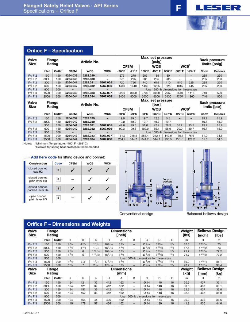
Flanged Safety Relief Valves · API Series Specifications – Orifice F
19
F
FlangeRating Article No.
Max. set pressure[psig] Back pressure
limits [psig]ValveSize
Inlet OutletCF8M WCB WC62
150 150 5264.039■ 5262.029■ – 275 275 285 185 80 – – 285 230
CF8M WCB WC6 -76° F1 -21° F 100° F 450° F 800° F 800° F 1000° F Conv. Bellows11/2 F 2
300L 150 5264.040■ 5262.030■ – 275 275 285 285 285 – – 285 23011/2 F 2300 150 5264.041■ 5262.031■ 5267.035■ 720 720 740 615 410 510 225 285 23011/2 F 2600 150 5264.042■ 5262.032■ 5267.036■ 1440 1440 1480 1235 825 1015 445 285 23011/2 F 2
1500 300 5264.043■ 5262.033■ 5267.037■ 2200 3600 3705 3080 2060 2540 1115 740 50011/2 F 32500 300 5264.044■ 5262.034■ 5267.038■ 3400 5000 5000 5000 3430 4230 1860 740 50011/2 F 3
900 300 – – – Use 1500-lb dimensions for these sizes11/2 F 3
FlangeRating Article No.
Max. set pressure[bar] Back pressure
limits [bar]ValveSize
Inlet OutletCF8M WCB WC62
150 150 5264.039■ 5262.029■ – 19.0 19.0 19.7 12.8 5.5 – – 19.7 15.9
CF8M WCB WC6 -60°C1 -29°C 38°C 232°C 427°C 427°C 538°C Conv. Bellows11/2 F 2
300L 150 5264.040■ 5262.030■ – 19.0 19.0 19.7 19.7 19.7 – – 19.7 15.911/2 F 2300 150 5264.041■ 5262.031■ 5267.035■ 49.6 49.6 51.0 42.4 28.3 35.2 15.5 19.7 15.9600 150 5264.042■ 5262.032■ 5267.036■ 99.3 99.3 102.0 85.1 56.9 70.0 30.7 19.7 15.911/2 F 2
1500 300 5264.043■ 5262.033■ 5267.037■ 151.7 248.2 255.4 212.4 142.0 175.1 76.9 51.0 34.511/2 F 32500 300 5264.044■ 5262.034■ 5267.038■ 234.4 344.7 344.7 344.7 236.5 291.6 128.2 51.0 34.511/2 F 3
900 300 – – – Use 1500-lb dimensions for these sizes11/2 F 3
Orifice F – Specification
FlangeRating
Dimensions[inch]
Bellows DesignWeight[lbs]
ValveSize
Inlet Outlet150 150 4 7/8
a Hm m
[inch] [lbs]
11/2 F 2
300 150 4 7/811/2 F 2600 150 4 7/811/2 F 2
1500 300 4 7/811/2 F 32500 300 5 1/211/2 F 3
900 300 Use 1500-lb dimensions for these sizes
4 3/4
b
66
61/2
7
1 1/4
s
1 13/32
1 13/32
1 3/4
2 1/4
16 3/16
H
16 3/16
16 3/16
17 3/16
17 3/16
6 3/8A
6 3/86 3/8
6 3/86 3/8
–
B
––
––
Ø 9/16
C
Ø 9/16
Ø 9/16
Ø 9/16
Ø 9/16
5 27/32
D
5 27/32
5 27/32
6 27/32
7 15/32
5/8 67.5 17 5/32 73300L 150 4 7/811/2 F 2 4 3/4 1 1/4 16 3/16 6 3/8 – Ø 9/16 5 27/32 5/8 67.5 17 5/32 73
71.7 17 5/32 77.271.7 17 5/32 77.2
80.0 17 3/16 85.192.2 17 3/16 98.4
E
5/85/8
5/85/8
11/2 F 3
FlangeRating
Dimensions[mm]
Bellows DesignWeight[kg]
ValveSize
Inlet Outlet150 150 124
a Hm m
[mm] [kg]
11/2 F 2
300 150 12411/2 F 2600 150 12411/2 F 2
1500 300 12411/2 F 32500 300 14011/2 F 3
900 300 Use 1500-lb dimensions for these sizes
121
b
152152
165178
32
s
3535
4457
412
H
412412
436436
162
A
162162
162162
–
B
––
––
Ø 14
C
Ø 14Ø 14
Ø 14Ø 14
148
D
148148
174189
16 30.6 437 33.1300L 150 12411/2 F 2 121 32 412 162 – Ø 14 148 16 30.6 437 33.1
32.5 437 35.032.5 437 35.0
36.3 436 38.641.8 436 44.6
E
1616
1616
11/2 F 3
Conventional design Balanced bellows design
Notes: 1Minimum Temperature: -450° F (-268° C)2Bellows for spring heat protection recommended
Code CF8M WCB WC6
closed bonnet,cap H2
Construction
closed bonnet,plain lever H3
closed bonnet, packed lever H4
open bonnet, plain lever H3
2
3
4
5
✓ ✓ ✓
– ✓ ✓
✓ ✓ ✓
– ✓ ✓
■ = Add here code for lifting device and bonnet:
Orifice F – Dimensions and Weights
Folder API Series 526 NEW 7/13/04 4:38 PM Page 19
LWN 470.18
Flanged Safety Relief Valves · API Series Selection Chart – Orifice G
Type 526
20
G
Folder API Series 526 NEW 7/13/04 4:38 PM Page 20
LWN 470.19
Flanged Safety Relief Valves · API Series Specifications – Orifice G
21
G
FlangeRating Article No.
Max. set pressure[psig] Back pressure
limits [psig]ValveSize
Inlet OutletCF8M WCB WC62
150 150 5264.110■ 5262.045■ – 275 275 285 185 80 – – 285 230
CF8M WCB WC6 -76° F1 -21° F 100° F 450° F 800° F 800° F 1000° F Conv. Bellows11/2 G 3
300L 150 5264.111■ 5262.046■ – 275 275 285 285 285 – – 285 23011/2 G 3300 150 5264.112■ 5262.047■ 5267.052■ 720 720 740 615 410 510 225 285 23011/2 G 3600 150 5264.113■ 5262.048■ 5267.053■ 1440 1440 1480 1235 825 1015 445 285 23011/2 G 3
1500 300 5264.115■ 5262.050■ 5267.055■ 2450 3600 3705 3080 2060 2540 1115 740 4702 G 32500 300 5264.116■ 5262.051■ 5267.056■ 2600 3600 3705 3705 3430 3705 1860 740 470
1600 2160 2220 1845 1235 1525 670 740 470
2 G 3
900 300 5264.114■ 5262.049■ 5267.054■11/2 G 3
FlangeRating Article No.
Max. set pressure[bar] Back pressure
limits [bar]ValveSize
Inlet OutletCF8M WCB WC62
150 150 5264.110■ 5262.045■ – 19.0 19.0 19.7 12.8 5.5 – – 19.7 15.9
CF8M WCB WC6 -60°C1 -29°C 38°C 232°C 427°C 427°C 538°C Conv. Bellows11/2 G 3
300L 150 5264.111■ 5262.046■ – 19.0 19.0 19.7 19.7 19.7 – – 19.7 15.911/2 G 3300 150 5264.112■ 5262.047■ 5267.052■ 49.6 49.6 51.0 42.4 28.3 35.2 15.5 19.7 15.911/2 G 3600 150 5264.113■ 5262.048■ 5267.053■ 99.3 99.3 102.0 85.1 56.9 70.0 30.6 19.7 15.911/2 G 3
1500 300 5264.115■ 5262.050■ 5267.055■ 168.9 248.2 255.4 212.4 142.0 175.1 76.8 51.0 32.42 G 32500 300 5264.116■ 5262.051■ 5267.056■ 179.3 248.2 255.4 255.4 236.5 255.4 128.2 51.0 32.4
110.3 148.9 153.1 127.2 85.1 105.1 46.2 51.0 32.4
2 G 3
900 300 5264.114■ 5262.049■ 5267.054■11/2 G 3
Orifice G – Specification
FlangeRating
Dimensions[inch]
Bellows DesignWeight[lbs]
ValveSize
Inlet Outlet150 150 4 7/8
a Hm m
[inch] [lbs]
11/2 G 3
300 150 4 7/811/2 G 3600 150 4 7/811/2 G 3
1500 300 6 1/82 G 32500 300 6 1/82 G 3
900 300
4 3/4
b
66
6 3/4
6 3/4
1 1/4
s
1 13/32
1 13/32
2 11/16
2 11/16
16 3/16
H
16 3/16
16 3/16
20 15/16
20 15/16
6 3/8A
6 3/86 3/8
7 1/47 1/4
–
B
––
4 11/32
4 11/32
Ø 9/16
C
Ø 9/16
Ø 9/16
Ø 9/16
Ø 9/16
5 27/32
D
5 27/32
5 27/32
7 13/16
7 13/16
5/8 67.5 17 21/32 73300L 150 4 7/811/2 G 3 4 3/4 1 1/4 16 3/16 6 3/8 – Ø 9/16 5 27/32 5/8 67.5 17 21/32 73
71.7 17 21/32 77.271.7 17 21/32 77.2
154.1 21 19/32 159.8154.1 21 19/32 159.8
E
5/85/8
5/85/8
4 7/8 6 1/2 1 3/4 173/16 6 3/8 – Ø 9/16 6 27/32 80.0 17 11/16 81.55/811/2 G 3
FlangeRating
Dimensions[mm]
Bellows DesignWeight[kg]
ValveSize
Inlet Outlet150 150 124
a Hm m
[mm] [kg]
11/2 G 3
300 150 12411/2 G 3600 150 12411/2 G 3
1500 300 1562 G 32500 300 1562 G 3
900 300
121
b
152152
172172
32
s
3535
6868
412
H
412412
532532
162
A
162162
184184
–
B
––
110110
124 165 44 436 162 –
Ø 14
C
Ø 14Ø 14
Ø 14Ø 14
148
D
148148
198198
16 30.6 450 33.1300L 150 12411/2 G 3 121 32 412 162 – Ø 14 148 16 30.6 450 33.1
32.5 450 35.032.5 450 35.0
69.9 549 72.569.9 549 72.5
E
1616
1616
Ø 14 174 36.3 449 38.61611/2 G 3
Conventional design Balanced bellows design
Notes: 1Minimum Temperature: -450° F (-268° C)2Bellows for spring heat protection recommended
Code CF8M WCB WC6
closed bonnet,cap H2
Construction
closed bonnet,plain lever H3
closed bonnet, packed lever H4
open bonnet, plain lever H3
2
3
4
5
✓ ✓ ✓
– ✓ ✓
✓ ✓ ✓
– ✓ ✓
■ = Add here code for lifting device and bonnet:
Orifice G – Dimensions and Weights
Folder API Series 526 NEW 7/13/04 4:39 PM Page 21

LWN 470.20
Flanged Safety Relief Valves · API Series Selection Chart – Orifice H
Type 526
22
H
Folder API Series 526 NEW 7/13/04 4:39 PM Page 22

LWN 470.21
Flanged Safety Relief Valves · API Series Specifications – Orifice H
23
H
FlangeRating Article No.
Max. set pressure[psig] Back pressure
limits [psig]ValveSize
Inlet OutletCF8M WCB WC62
150 150 5264.152■ 5262.142■ – 275 275 285 185 80 – – 285 230
CF8M WCB WC6 -76° F1 -21° F 100° F 450° F 800° F 800° F 1000° F Conv. Bellows11/2 H 3
300L 150 5264.153■ 5262.143■ – 275 275 285 285 285 – – 285 23011/2 H 3300 150 5264.154■ 5262.144■ 5267.148■ 720 720 740 615 410 510 225 285 2302 H 3
900 150 5264.156■ 5262.146■ 5267.150■ 1485 2160 2220 1845 1235 1225 670 285 2301440 1440 1480 1235 825 815 445 285 230
2 H 31500 300 5264.157■ 5262.147■ 5267.151■ 1600 2750 2750 2750 2060 2040 1115 740 4152 H 3
600 150 5264.155■ 5262.145■ 5267.149■2 H 3
FlangeRating Article No.
Max. set pressure[bar] Back pressure
limits [bar]ValveSize
Inlet OutletCF8M WCB WC62
150 150 5264.152■ 5262.142■ – 19.0 19.0 19.7 12.8 5.5 – – 19.7 15.9
CF8M WCB WC6 -60°C1 -29°C 38°C 232°C 427°C 427°C 538°C Conv. Bellows11/2 H 3
300L 150 5264.153■ 5262.143■ – 19.0 19.0 19.7 19.7 19.7 – – 19.7 15.911/2 H 3300 150 5264.154■ 5262.144■ 5267.148■ 49.6 49.6 51.0 42.4 28.3 35.2 15.5 19.7 15.92 H 3
900 150 5264.156■ 5262.146■ 5267.150■ 102.4 148.9 153.1 127.2 85.1 84.5 46.2 19.7 15.92 H 31500 300 5264.157■ 5262.147■ 5267.151■ 110.3 189.6 189.6 189.6 142.0 140.7 76.9 51.0 28.6
99.3 99.3 102.0 85.1 56.9 56.2 30.7 19.7 15.9
2 H 3
600 150 5264.155■ 5262.145■ 5267.149■2 H 3
Orifice H – Specification
FlangeRating
Dimensions[inch]
Bellows DesignWeight[lbs]
ValveSize
Inlet Outlet150 150 5 1/8
a Hm m
[inch] [lbs]
11/2 H 3300L 150 5 1/811/2 H 3300 150 5 1/82 H 3
900 150 6 1/162 H 31500 300 6 1/162 H 3
600 150
4 7/8
b
4 7/8
4 7/8
6 3/8
6 3/8
1 1/2
s
1 1/2
1 11/16
2 3/16
2 3/16
16 3/16
H
16 3/16
21 3/32
21 1/8
21 1/8
6 3/8A
6 3/87 1/4
7 1/47 1/4
–
B
–4 11/32
4 11/32
4 11/32
Ø 9/16
C
Ø 9/16
Ø 9/16
Ø 9/16
Ø 9/16
6 3/32
D
6 3/32
6 31/32
7 15/16
7 15/16
5/8 67.5 17 21/32 73.067.5 17 21/32 73.098.3 22 3/32 106.7
137.1 22 1/8 143.9137.1 22 1/8 143.9
E
5/8
5 1/8 4 7/8 1 11/16 21 3/32 7 1/4 4 11/32 Ø 9/16 6 31/32 98.3 22 3/32 106.75/8
5/8
5/85/8
2 H 31
600 150 6 1/16 6 3/8 2 3/16 21 1/8 7 1/4 4 11/32 Ø 9/16 7 15/16 137.1 22 1/8 143.95/82 H 32
FlangeRating
Dimensions[mm]
Bellows DesignWeight[kg]
ValveSize
Inlet Outlet150 150 130
a Hm m
[mm] [kg]
11/2 H 3300L 150 13011/2 H 3300 150 1302 H 3
900 150 1542 H 31500 300 1542 H 3
600 150
124
b
124124
162162
38
s
3843
5656
412
H
412536
537537
162
A
162184
184184
–
B
–110
110110
Ø 14
C
Ø 14Ø 14
Ø 14Ø 14
155
D
155177
202202
16 30.6 450 33.130.3 450 33.144.6 562 48.4
62.2 563 65.362.2 563 65.3
E
16
600 150 1302 H 31 124 43 536 184 110 Ø 14 177 44.6 562 48.416154 162 56 537 184 110 Ø 14 202 62.2 563 65.316
16
1616
2 H 32
1 dimensions for WC6 material2 dimensions for CF8M and WCB material
Conventional design Balanced bellows design
Notes: 1Minimum Temperature: -450° F (-268° C)2Bellows for spring heat protection recommended
Code CF8M WCB WC6
closed bonnet,cap H2
Construction
closed bonnet,plain lever H3
closed bonnet, packed lever H4
open bonnet, plain lever H3
2
3
4
5
✓ ✓ ✓
– ✓ ✓
✓ ✓ ✓
– ✓ ✓
■ = Add here code for lifting device and bonnet:
Orifice H – Dimensions and Weights
Folder API Series 526 NEW 7/13/04 4:39 PM Page 23

LWN 470.22
Flanged Safety Relief Valves · API Series Selection Chart – Orifice J
Type 526
24
J
Folder API Series 526 NEW 7/13/04 4:39 PM Page 24
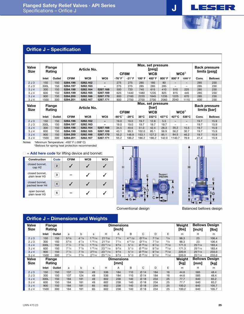
LWN 470.23
Flanged Safety Relief Valves · API Series Specifications – Orifice J
25
J
FlangeRating Article No.
Max. set pressure[psig] Back pressure
limits [psig]ValveSize
Inlet OutletCF8M WCB WC62
150 150 5264.196■ 5262.162■ – 275 275 285 185 80 – – 285 230
CF8M WCB WC6 -76° F1 -21° F 100° F 450° F 800° F 800° F 1000° F Conv. Bellows2 J 3
300L 150 5264.197■ 5262.163■ – 275 275 285 285 285 – – 285 230
625 1440 1480 1235 825 815 445 285 230
2 J 3300 150 5264.198■ 5262.164■ 5267.168■ 500 720 740 615 410 510 225 285 2303 J 4
900 150 5264.200■ 5262.166■ 5267.170■ 800 2160 2220 1845 1235 1225 670 285 2303 J 41500 300 5264.201■ 5262.167■ 5267.171■ 800 2700 2700 2700 2060 2040 1115 600 2303 J 4
600 150 5264.199■ 5262.165■ 5267.169■3 J 4
FlangeRating Article No.
Max. set pressure[bar] Back pressure
limits [bar]ValveSize
Inlet OutletCF8M WCB WC62
150 150 5264.196■ 5262.162■ – 19.0 19.0 19.7 12.8 5.5 – – 19.7 15.9
CF8M WCB WC6 -60°C1 -29°C 38°C 232°C 427°C 427°C 538°C Conv. Bellows2 J 3
300L 150 5264.197■ 5262.163■ – 19.0 19.0 19.7 19.7 19.7 – – 19.7 15.9
43.1 99.3 102.0 85.1 56.9 56.2 30.7 19.7 15.9
2 J 3300 150 5264.198■ 5262.164■ 5267.168■ 34.5 49.6 51.0 42.4 28.3 35.2 15.5 19.7 15.93 J 4
900 150 5264.200■ 5262.166■ 5267.170■ 55.2 148.9 153,1 127.2 85.1 84.5 46.2 19.7 15.93 J 41500 300 5264.201■ 5262.167■ 5267.171■ 55.2 186.2 186.2 186.2 142.0 1140.7 76.9 41.4 15.93 J 4
600 150 5264.199■ 5262.165■ 5267.169■3 J 4
Orifice J – Specification
FlangeRating
Dimensions[inch]
Bellows DesignWeight[lbs]
ValveSize
Inlet Outlet150 150 5 3/8
a Hm m
[inch] [lbs]
2 J 3300 150 5 3/82 J 3300L 150 7 1/43 J 4
900 150 7 1/43 J 41500 300 7 1/43 J 4
600 150
4 7/8
b
4 7/8
7 1/8
7 1/87 1/8
1 15/16
s
1 15/16
1 15/16
2 9/16
2 9/16
21 3/32
H
21 3/32
23 11/16
23 11/16
23 11/16
7 1/4A
7 1/49 3/8
9 3/89 3/8
4 11/32
B
4 11/32
5 1/2
5 1/25 1/2
Ø 9/16
C
Ø 9/16
Ø 23/32
Ø 23/32
Ø 23/32
7 7/32
D
7 7/32
9 7/32
9 7/32
9 7/32
5/8 98.3 23 106.498.3 23 106.4171.3 25 3/16 183.4
220.9 25 3/16 233.0220.9 25 3/16 233.0
E
5/8
7 1/4 7 1/8 1 15/16 23 11/16 9 3/8 5 1/2 Ø 23/32 9 7/32 171.3 25 3/16 183.431/32
31/32
31/3231/32
3 J 4
FlangeRating
Dimensions[mm]
Bellows DesignWeight[kg]
ValveSize
Inlet Outlet
150 150 137
a Hm m
[mm] [kg]
2 J 3300 150 1372 J 3300L 150 1843 J 4
900 150 1843 J 41500 300 1843 J 4
600 150
124
b
124181
181181
49
s
4949
6565
536
H
536602
602602
184
A
184238
238238
110
B
110140
140140
Ø 14
C
Ø 14Ø 18
Ø 18Ø 18
184
D
184234
234234
16 44.6 585 48.444.6 585 48.477.7 640 83.2
100.2 640 105.7100.2 640 105.7
E
16
184 181 49 602 238 140 Ø 18 234 77.7 640 83.22525
2525
3 J 4
Conventional design Balanced bellows design
Notes: 1Minimum Temperature: -450° F (-268° C)2Bellows for spring heat protection recommended
Code CF8M WCB WC6
closed bonnet,cap H2
Construction
closed bonnet,plain lever H3
closed bonnet, packed lever H4
open bonnet, plain lever H3
2
3
4
5
✓ ✓ ✓
– ✓ ✓
✓ ✓ ✓
– ✓ ✓
■ = Add here code for lifting device and bonnet:
Orifice J – Dimensions and Weights
Folder API Series 526 NEW 7/13/04 4:39 PM Page 25

LWN 470.24
Flanged Safety Relief Valves · API Series Selection Chart – Orifice K
Type 526
26
K
Folder API Series 526 NEW 7/13/04 4:39 PM Page 26
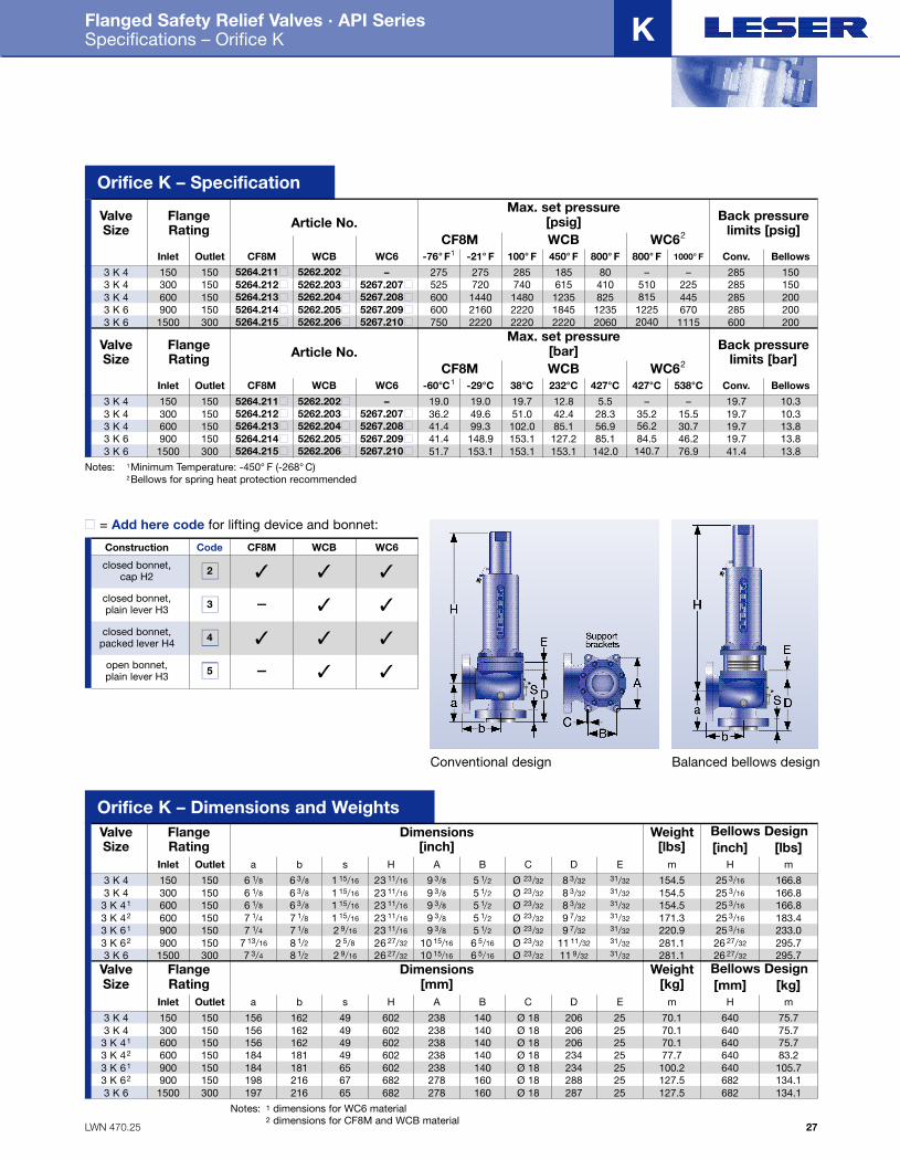
LWN 470.25
Flanged Safety Relief Valves · API Series Specifications – Orifice K
27
K
FlangeRating Article No.
Max. set pressure[psig] Back pressure
limits [psig]ValveSize
Inlet OutletCF8M WCB WC62
150 150 5264.211■ 5262.202■ – 275 275 285 185 80 – – 285 150
CF8M WCB WC6 -76° F1 -21° F 100° F 450° F 800° F 800° F 1000° F Conv. Bellows3 K 4
300 150 5264.212■ 5262.203■ 5267.207■ 525 720 740 615 410 510 225 285 150
600 2160 2220 1845 1235 1225 670 285 200
3 K 4600 150 5264.213■ 5262.204■ 5267.208■ 600 1440 1480 1235 825 815 445 285 2003 K 4
1500 300 5264.215■ 5262.206■ 5267.210■ 750 2220 2220 2220 2060 2040 1115 600 2003 K 6900 150 5264.214■ 5262.205■ 5267.209■3 K 6
FlangeRating Article No.
Max. set pressure[bar] Back pressure
limits [bar]ValveSize
Inlet OutletCF8M WCB WC62
150 150 5264.211■ 5262.202■ – 19.0 19.0 19.7 12.8 5.5 – – 19.7 10.3
CF8M WCB WC6 -60°C1 -29°C 38°C 232°C 427°C 427°C 538°C Conv. Bellows3 K 4
300 150 5264.212■ 5262.203■ 5267.207■ 36.2 49.6 51.0 42.4 28.3 35.2 15.5 19.7 10.3
41.4 148.9 153.1 127.2 85.1 84.5 46.2 19.7 13.8
3 K 4600 150 5264.213■ 5262.204■ 5267.208■ 41.4 99.3 102.0 85.1 56.9 56.2 30.7 19.7 13.83 K 4
1500 300 5264.215■ 5262.206■ 5267.210■ 51.7 153.1 153.1 153.1 142.0 140.7 76.9 41.4 13.83 K 6900 150 5264.214■ 5262.205■ 5267.209■3 K 6
Orifice K – Specification
FlangeRating
Dimensions[inch]
Bellows DesignWeight[lbs]
ValveSize
Inlet Outlet150 150 6 1/8
a Hm m
[inch] [lbs]
3 K 4300 150 6 1/83 K 4600 150 6 1/83 K 41
900 150 7 1/43 K 61
900 150 7 13/163 K 62
600 150
6 3/8
b
6 3/8
6 3/8
7 1/88 1/2
1 15/16
s
1 15/16
1 15/16
2 9/16
2 5/8
23 11/16
H
23 11/16
23 11/16
23 11/16
26 27/32
9 3/8A
9 3/89 3/8
9 3/810 15/16
5 1/2
B
5 1/2
5 1/2
5 1/2
6 5/16
Ø 23/32
C
Ø 23/32
Ø 23/32
Ø 23/32
Ø 23/32
8 3/32
D
8 3/32
8 3/32
9 7/32
11 11/32
31/32 154.5 25 3/16 166.8154.5 25 3/16 166.8154.5 25 3/16 166.8
220.9 25 3/16 233.0281.1 26 27/32 295.7
E
31/32
7 1/4 7 1/8 1 15/16 23 11/16 9 3/8 5 1/2 Ø 23/32 9 7/32 171.3 25 3/16 183.431/32
31/32
31/32
1500 300 7 3/43 K 6 8 1/2 2 9/16 26 27/32 10 15/16 6 5/16 Ø 23/32 11 9/32 281.1 26 27/32 295.731/32
31/32
3 K 42
FlangeRating
Dimensions[mm]
Bellows DesignWeight[kg]
ValveSize
Inlet Outlet150 150 156
a Hm m
[mm] [kg]
3 K 4300 150 1563 K 4600 150 1563 K 41
900 150 1843 K 61
900 150 1983 K 62
600 150
162
b
162162
181216
49
s
4949
6567
602
H
602602
602682
238
A
238238
238278
140
B
140140
140160
Ø 18
C
Ø 18Ø 18
Ø 18Ø 18
206
D
206206
234288
25 70.1 640 75.770.1 640 75.770.1 640 75.7
100.2 640 105.7127.5 682 134.1
E
25
184 181 49 602 238 140 Ø 18 234 77.7 640 83.22525
25
1500 300 1973 K 6 216 65 682 278 160 Ø 18 287 127.5 682 134.12525
3 K 42
Notes: 1 dimensions for WC6 material2 dimensions for CF8M and WCB material
Conventional design Balanced bellows design
Notes: 1Minimum Temperature: -450° F (-268° C)2Bellows for spring heat protection recommended
Code CF8M WCB WC6
closed bonnet,cap H2
Construction
closed bonnet,plain lever H3
closed bonnet, packed lever H4
open bonnet, plain lever H3
2
3
4
5
✓ ✓ ✓
– ✓ ✓
✓ ✓ ✓
– ✓ ✓
■ = Add here code for lifting device and bonnet:
Orifice K – Dimensions and Weights
Folder API Series 526 NEW 7/13/04 4:39 PM Page 27
LWN 470.26
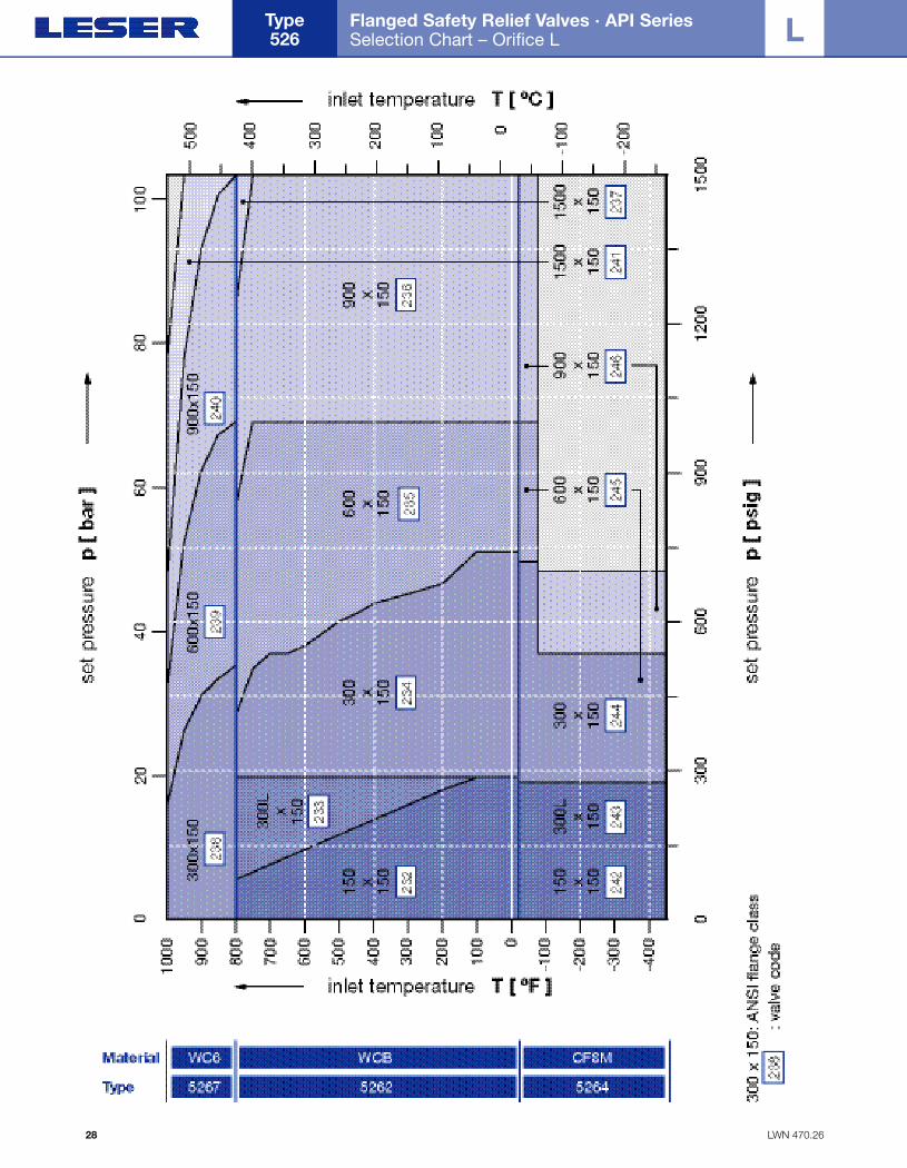
Flanged Safety Relief Valves · API Series Selection Chart – Orifice L
Type 526
28
L
Folder API Series 526 NEW 7/13/04 4:39 PM Page 28
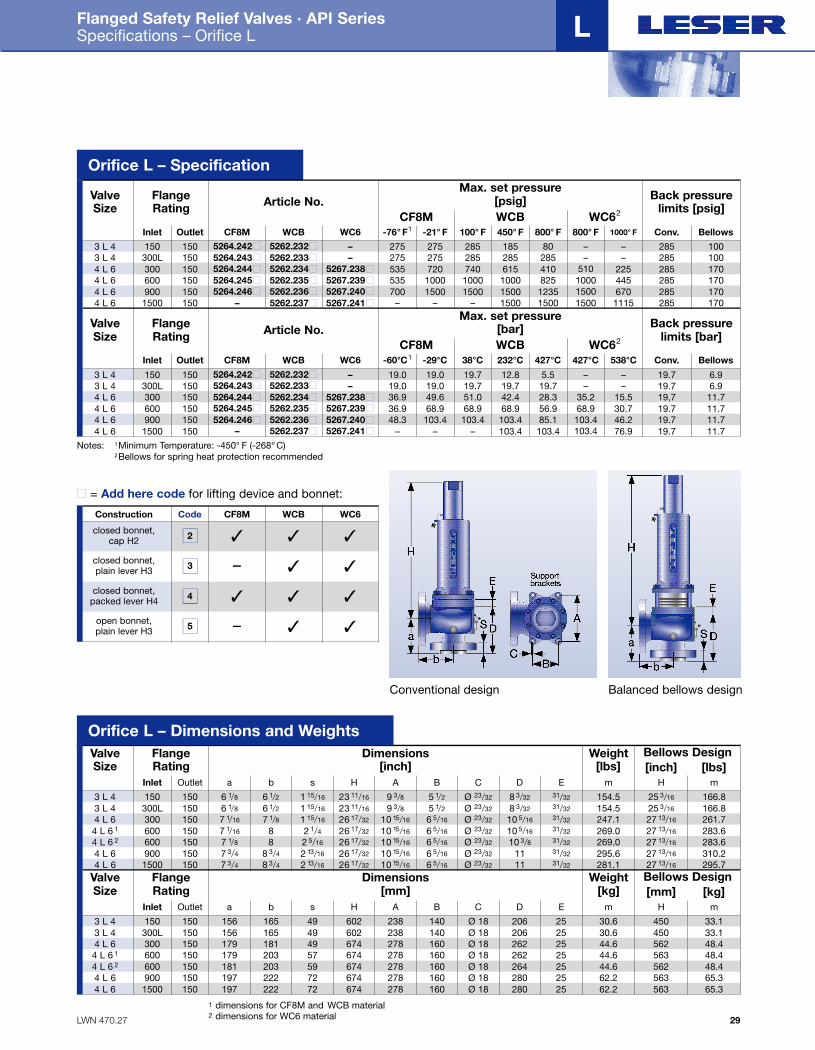
LWN 470.27
Flanged Safety Relief Valves · API Series Specifications – Orifice L
29
L
FlangeRating Article No.
Max. set pressure[psig] Back pressure
limits [psig]ValveSize
Inlet OutletCF8M WCB WC62
150 150 5264.242■ 5262.232■ – 275 275 285 185 80 – – 285 100
CF8M WCB WC6 -76° F1 -21° F 100° F 450° F 800° F 800° F 1000° F Conv. Bellows3 L 4
300L 150 5264.243■ 5262.233■ – 275 275 285 285 285 – – 285 100
535 1000 1000 1000 825 1000 445 285 170
3 L 4300 150 5264.244■ 5262.234■ 5267.238■ 535 720 740 615 410 510 225 285 1704 L 6
900 150 5264.246■ 5262.236■ 5267.240■ 700 1500 1500 1500 1235 1500 670 285 1704 L 61500 150 – 5262.237■ 5267.241■ – – – 1500 1500 1500 1115 285 1704 L 6
600 150 5264.245■ 5262.235■ 5267.239■4 L 6
FlangeRating Article No.
Max. set pressure[bar] Back pressure
limits [bar]ValveSize
Inlet OutletCF8M WCB WC62
150 150 5264.242■ 5262.232■ – 19.0 19.0 19.7 12.8 5.5 – – 19.7 6.9
CF8M WCB WC6 -60°C1 -29°C 38°C 232°C 427°C 427°C 538°C Conv. Bellows
3 L 4300L 150 5264.243■ 5262.233■ – 19.0 19.0 19.7 19.7 19.7 – – 19.7 6.9
36.9 68.9 68.9 68.9 56.9 68.9 30.7 19.7 11.7
3 L 4300 150 5264.244■ 5262.234■ 5267.238■ 36.9 49.6 51.0 42.4 28.3 35.2 15.5 19,7 11.74 L 6
900 150 5264.246■ 5262.236■ 5267.240■ 48.3 103.4 103.4 103.4 85.1 103.4 46.2 19.7 11.74 L 61500 150 – 5262.237■ 5267.241■ – – – 103.4 103.4 103.4 76.9 19.7 11.74 L 6
600 150 5264.245■ 5262.235■ 5267.239■4 L 6
Orifice L – Specification
FlangeRating
Dimensions[inch]
Bellows DesignWeight[lbs]
ValveSize
Inlet Outlet
150 150 6 1/8
a Hm m
[inch] [lbs]
3 L 4300L 150 6 1/83 L 4300 150 7 1/164 L 6
600 150 7 1/84 L 6 2
900 150 7 3/44 L 6
600 150
6 1/2b
6 1/27 1/8
88 3/4
1 15/16
s
1 15/16
1 15/16
2 5/16
2 13/16
23 11/16
H
23 11/16
26 17/32
26 17/32
26 17/32
9 3/8A
9 3/810 15/16
10 15/16
10 15/16
5 1/2
B
5 1/2
6 5/16
6 5/16
6 5/16
Ø 23/32
C
Ø 23/32
Ø 23/32
Ø 23/32
Ø 23/32
8 3/32
D
8 3/32
10 5/16
10 3/811
31/32 154.5 25 3/16 166.8154.5 25 3/16 166.8247.1 27 13/16 261.7
269.0 27 13/16 283.6
295.7295.6 27 13/16 310.2
E
31/32
7 1/16 8 2 1/4 26 17/32 10 15/16 6 5/16 Ø 23/32 10 5/16 269.0 27 13/16 283.631/32
31/32
31/32
1500 150 7 3/44 L 6 8 3/4 2 13/16 26 17/32 10 15/16 6 5/16 Ø 23/32 11 281.1 27 13/1631/32
31/32
4 L 6 1
FlangeRating
Dimensions[mm]
Bellows DesignWeight[kg]
ValveSize
Inlet Outlet
150 150 156
a Hm m
[mm] [kg]
3 L 4300L 150 1563 L 4300 150 1794 L 6
600 150 1814 L 6 2
1500 150 1974 L 6
600 150
165
b
165181
203
222
49
s
4949
59
72
602
H
602674
674
674
238
A
238278
278
278
140
B
140160
160
160
Ø 18
C
Ø 18Ø 18
Ø 18
Ø 18
206
D
206262
264
280
25 30.6 450 33.130.6 450 33.144.6 562 48.4
44.6 562 48.4
62.2 56365.3
E
25
179 203 57 674 278 160 Ø 18 262 44.6 563 48.425
197 222 72 674 278 160 Ø 18 280 62.2 56365.3
25
25
25
25
4 L 6 1
900 1504 L 6
1 dimensions for CF8M and WCB material2 dimensions for WC6 material
Conventional design Balanced bellows design
Notes: 1Minimum Temperature: -450° F (-268° C)2Bellows for spring heat protection recommended
Code CF8M WCB WC6
closed bonnet,cap H2
Construction
closed bonnet,plain lever H3
closed bonnet, packed lever H4
open bonnet, plain lever H3
2
3
4
5
✓ ✓ ✓
– ✓ ✓
✓ ✓ ✓
– ✓ ✓
■ = Add here code for lifting device and bonnet:
Orifice L – Dimensions and Weights
Folder API Series 526 NEW 7/13/04 4:40 PM Page 29
LWN 470.28
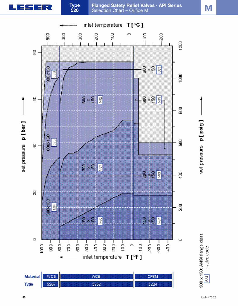
Flanged Safety Relief Valves · API Series Selection Chart – Orifice M
Type 526
30
M
Folder API Series 526 NEW 7/13/04 4:40 PM Page 30
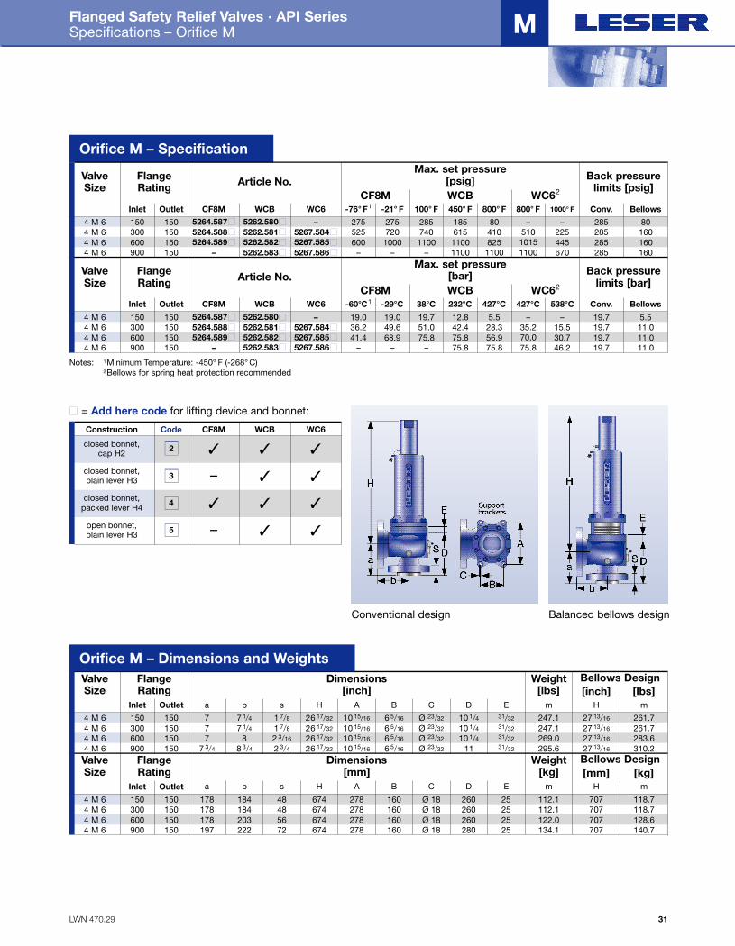
LWN 470.29
Flanged Safety Relief Valves · API Series Specifications – Orifice M
31
M
FlangeRating Article No.
Max. set pressure[psig] Back pressure
limits [psig]ValveSize
Inlet OutletCF8M WCB WC62
150 150 5264.587■ 5262.580■ – 275 275 285 185 80 – – 285 80
CF8M WCB WC6 -76° F1 -21° F 100° F 450° F 800° F 800° F 1000° F Conv. Bellows4 M 6
300 150 5264.588■ 5262.581■ 5267.584■ 525 720 740 615 410 510 225 285 160
– – – 1100 1100 1100 670 285 160
4 M 6600 150 5264.589■ 5262.582■ 5267.585■ 600 1000 1100 1100 825 1015 445 285 1604 M 6900 150 – 5262.583■ 5267.586■4 M 6
FlangeRating Article No.
Max. set pressure[bar] Back pressure
limits [bar]ValveSize
Inlet OutletCF8M WCB WC62
150 150 5264.587■ 5262.580■ – 19.0 19.0 19.7 12.8 5.5 – – 19.7 5.5
CF8M WCB WC6 -60°C1 -29°C 38°C 232°C 427°C 427°C 538°C Conv. Bellows
4 M 6300 150 5264.588■ 5262.581■ 5267.584■ 36.2 49.6 51.0 42.4 28.3 35.2 15.5 19.7 11.0
– – – 75.8 75.8 75.8 46.2 19.7 11.0
4 M 6600 150 5264.589■ 5262.582■ 5267.585■ 41.4 68.9 75.8 75.8 56.9 70.0 30.7 19.7 11.04 M 6900 150 – 5262.583■ 5267.586■4 M 6
Orifice M – Specification
FlangeRating
Dimensions[inch]
Bellows DesignWeight[lbs]
ValveSize
Inlet Outlet150 150 7
a Hm m
[inch] [lbs]
4 M 6300 150 74 M 6600 150 74 M 6900 150
7 1/4b
7 1/48
1 7/8
s
1 7/8
2 3/16
26 17/32
H
26 17/32
26 17/32
10 15/16
A
10 15/16
10 15/16
6 5/16
B
6 5/16
6 5/16
Ø 23/32
C
Ø 23/32
Ø 23/32
10 1/4D
10 1/410 1/4
31/32 247.1 27 13/16 261.7247.1 27 13/16 261.7269.0 27 13/16 283.6
E
31/32
7 3/4 8 3/4 2 3/4 26 17/32 10 15/16 6 5/16 Ø 23/32 11 295.6 27 13/16 310.231/32
31/32
4 M 6FlangeRating
Dimensions[mm]
Bellows DesignWeight[kg]
ValveSize
Inlet Outlet150 150 178
a Hm m[mm] [kg]
4 M 6300 150 1784 M 6600 150 1784 M 6900 150
184
b
184203
48
s
4856
674
H
674674
278
A
278278
160
B
160160
Ø 18
C
Ø 18Ø 18
260
D
260260
25 112.1 707 118.7112.1 707 118.7122.0 707 128.6
E
25
197 222 72 674 278 160 Ø 18 280 134.1 707 140.72525
4 M 6
Conventional design Balanced bellows design
Notes: 1Minimum Temperature: -450° F (-268° C)2Bellows for spring heat protection recommended
Code CF8M WCB WC6
closed bonnet,cap H2
Construction
closed bonnet,plain lever H3
closed bonnet, packed lever H4
open bonnet, plain lever H3
2
3
4
5
✓ ✓ ✓
– ✓ ✓
✓ ✓ ✓
– ✓ ✓
■ = Add here code for lifting device and bonnet:
Orifice M – Dimensions and Weights
Folder API Series 526 NEW 7/13/04 4:40 PM Page 31
LWN 470.30
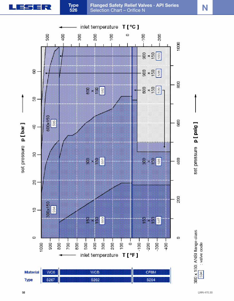
Flanged Safety Relief Valves · API Series Selection Chart – Orifice N
Type 526
32
N
Folder API Series 526 NEW 7/13/04 4:40 PM Page 32
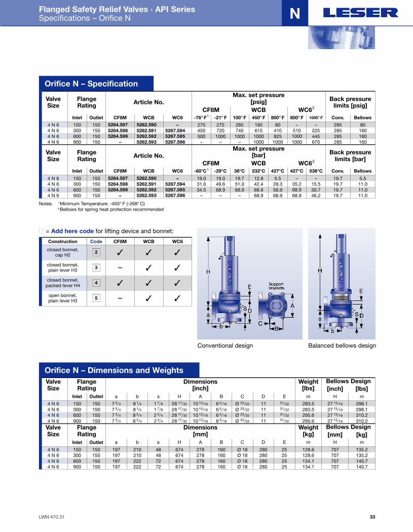
LWN 470.31
Flanged Safety Relief Valves · API Series Specifications – Orifice N
33
N
FlangeRating Article No.
Max. set pressure[psig] Back pressure
limits [psig]ValveSize
Inlet OutletCF8M WCB WC62
150 150 5264.597■ 5262.590■ – 275 275 285 185 80 – – 285 80
CF8M WCB WC6 -76° F1 -21° F 100° F 450° F 800° F 800° F 1000° F Conv. Bellows4 N 6
300 150 5264.598■ 5262.591■ 5267.594■ 450 720 740 615 410 510 225 285 160
– – – 1000 1000 1000 670 285 160
4 N 6600 150 5264.599■ 5262.592■ 5267.595■ 500 1000 1000 1000 825 1000 445 285 1604 N 6900 150 – 5262.593■ 5267.596■4 N 6
FlangeRating Article No.
Max. set pressure[bar] Back pressure
limits [bar]ValveSize
Inlet OutletCF8M WCB WC62
150 150 5264.597■ 5262.590■ – 19.0 19.0 19.7 12.8 5.5 – – 19.7 5.5
CF8M WCB WC6 -60°C1 -29°C 38°C 232°C 427°C 427°C 538°C Conv. Bellows
4 N 6300 150 5264.598■ 5262.591■ 5267.594■ 31.0 49.6 51.0 42.4 28.3 35.2 15.5 19.7 11.0
– – – 68.9 68.9 68.9 46.2 19.7 11.0
4 N 6600 150 5264.599■ 5262.592■ 5267.595■ 34.5 68.9 68.9 68.9 56.9 68.9 30.7 19.7 11.04 N 6900 150 – 5262.593■ 5267.596■4 N 6
Orifice N – Specification
FlangeRating
Dimensions[inch]
Bellows DesignWeight[lbs]
ValveSize
Inlet Outlet150 150 7 3/4
a Hm m
[inch] [lbs]
4 N 6300 150 7 3/44 N 6600 150 7 3/44 N 6900 150
8 1/4b
8 1/48 3/4
1 7/8
s
1 7/8
2 3/4
26 17/32
H
26 17/32
26 17/32
10 15/16
A
10 15/16
10 15/16
6 5/16
B
6 5/16
6 5/16
Ø 23/32
C
Ø 23/32
Ø 23/32
11
D
1111
31/32 283.5 27 13/16 298.1283.5 27 13/16 298.1295.6 27 13/16 310.2
E
31/32
7 3/4 8 3/4 2 3/4 26 17/32 10 15/16 6 5/16 Ø 23/32 11 295.6 27 13/16 310.231/32
31/32
4 N 6FlangeRating
Dimensions[mm]
Bellows DesignWeight[kg]
ValveSize
Inlet Outlet150 150 197
a Hm m[mm] [kg]
4 N 6300 150 1974 N 6600 150 1974 N 6900 150
210
b
210222
48
s
4872
674
H
674674
278
A
278278
160
B
160160
Ø 18
C
Ø 18Ø 18
280
D
280280
25 128.6 707 135.2128.6 707 135.2134.1 707 140.7
E
25
197 222 72 674 278 160 Ø 18 280 134.1 707 140.72525
4 N 6
Conventional design Balanced bellows design
Notes: 1Minimum Temperature: -450° F (-268° C)2Bellows for spring heat protection recommended
Code CF8M WCB WC6
closed bonnet,cap H2
Construction
closed bonnet,plain lever H3
closed bonnet, packed lever H4
open bonnet, plain lever H3
2
3
4
5
✓ ✓ ✓
– ✓ ✓
✓ ✓ ✓
– ✓ ✓
■ = Add here code for lifting device and bonnet:
Orifice N – Dimensions and Weights
Folder API Series 526 NEW 7/13/04 4:40 PM Page 33
LWN 470.32
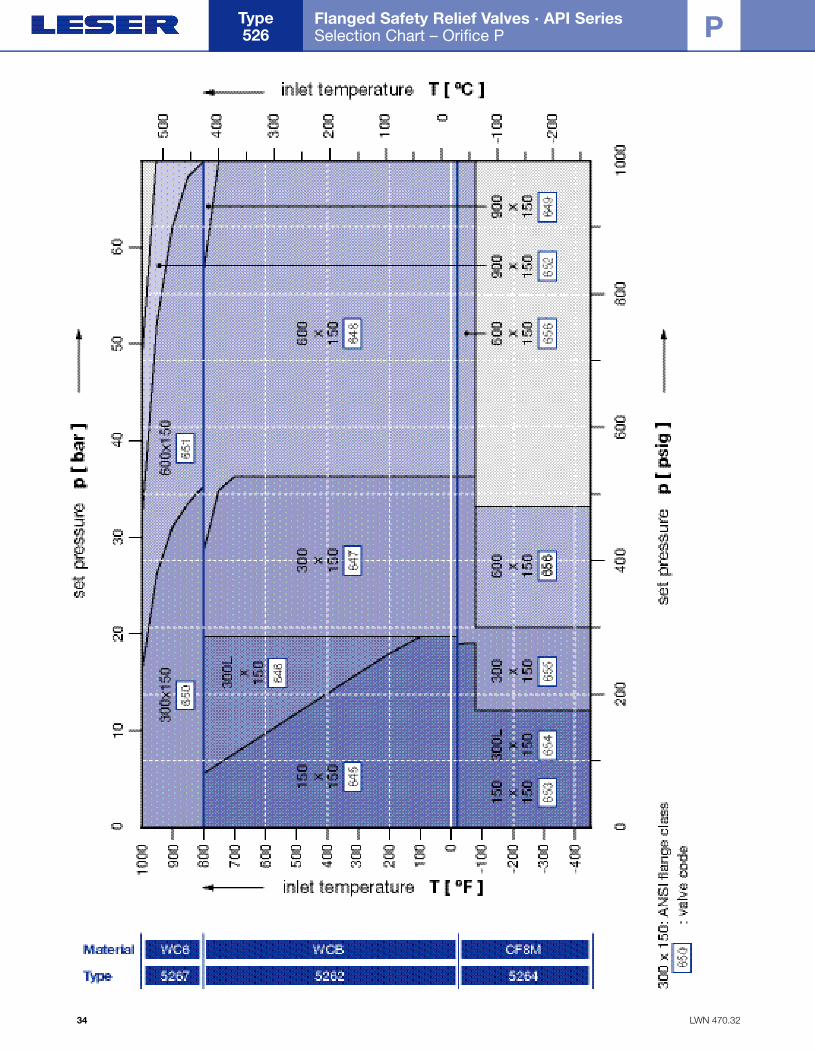
Flanged Safety Relief Valves · API Series Selection Chart – Orifice P
Type 526
34
P
Folder API Series 526 NEW 7/13/04 4:40 PM Page 34
LWN 470.33
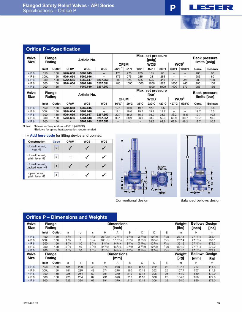
Flanged Safety Relief Valves · API Series Specifications – Orifice P
35
P
FlangeRating Article No.
Max. set pressure[psig] Back pressure
limits [psig]ValveSize
Inlet OutletCF8M WCB WC62
150 150 5264.653■ 5262.645■ – 175 275 285 185 80 – – 285 80
CF8M WCB WC6 -76° F1 -21° F 100° F 450° F 800° F 800° F 1000° F Conv. Bellows4 P 6
300L 150 5264.654■ 5262.646■ – 175 275 285 28 285 – – 285 80
480 1000 1000 1000 825 1000 445 285 150
4 P 6300 150 5264.655■ 5262.647■ 5267.650■ 300 525 525 525 410 510 225 285 1504 P 6
900 150 – 5262.649■ 5267.652■ – – – 1000 1000 1000 670 285 1504 P 6600 150 5264.656■ 5262.648■ 5267.651■4 P 6
FlangeRating Article No.
Max. set pressure[bar] Back pressure
limits [bar]ValveSize
Inlet OutletCF8M WCB WC62
150 150 5264.653■ 5262.645■ – 12.1 19.0 19.7 12.8 5.5 – – 19.7 5.5
CF8M WCB WC6 -60°C1 -29°C 38°C 232°C 427°C 427°C 538°C Conv. Bellows4 P 6
300L 150 5264.654■ 5262.646■ – 12.1 19.0 19.7 19.7 19.7 – – 19.7 5.5
33.1 68.9 68.9 68.9 56.9 68.9 30.7 19.7 10.3
4 P 6300 150 5264.655■ 5262.647■ 5267.650■ 20.7 36.2 36.2 36.2 28.3 35.2 15.5 19.7 10.34 P 6
900 150 – 5262.649■ 5267.652■ – – – 68.9 68.9 68.9 46.2 19.7 10.34 P 6600 150 5264.656■ 5264.648■ 5267.651■4 P 6
Orifice P – Specification
FlangeRating
Dimensions[inch]
Bellows DesignWeight[lbs]
ValveSize
Inlet Outlet150 150 7 1/8
a Hm m
[inch] [lbs]
4 P 6300L 150 7 1/84 P 6300 150 8 7/84 P 6
900 150 8 7/84 P 6600 150
9
b
910
10
1 7/8
s
1 7/8
2 7/16
2 7/16
26 17/32
H
26 17/32
315/32
315/32
10 15/16
A
10 15/16
14 9/16
14 9/16
6 5/16
B
6 5/16
8 9/32
8 9/32
Ø 23/32
C
Ø 23/32
Ø 23/32
Ø 23/32
10 5/16
D
10 5/16
12 1/16
12 1/16
31/32 237.4 27 13/16 253.1237.4 27 13/16 253.1361.6 27 13/16 379.2
361.6 27 13/16 379.2
E
31/32
8 7/8 10 2 7/16 315/32 14 9/16 8 9/32 Ø 23/32 12 1/16 361.6 27 13/16 379.231/32
31/32
31/32
4 P 6
FlangeRating
Dimensions[mm]
Bellows DesignWeight[kg]
ValveSize
Inlet Outlet150 150 181
a Hm m
[mm] [kg]
4 P 6300L 150 1814 P 6300 150 2254 P 6
900 150 2254 P 6600 150
229
b
229254
254
48
s
4862
62
674
H
674791
791
278
A
278
225 254 62 791 370370
370
160
B
160210
210
Ø 18
C
Ø 18Ø 18
Ø 18
262
D
262306
306
25 107.7 707 114.8107.7 707 114.8164.0 850 172.0
164.0 850 172.0
E
25
210 Ø 18 306 164.0 850 172.02525
254 P 6
Conventional design Balanced bellows design
Notes: 1Minimum Temperature: -450° F (-268° C)2Bellows for spring heat protection recommended
Code CF8M WCB WC6
closed bonnet,cap H2
Construction
closed bonnet,plain lever H3
closed bonnet, packed lever H4
open bonnet, plain lever H3
2
3
4
5
✓ ✓ ✓
– ✓ ✓
✓ ✓ ✓
– ✓ ✓
■ = Add here code for lifting device and bonnet:
Orifice P – Dimensions and Weights
Folder API Series 526 NEW 7/13/04 4:40 PM Page 35
LWN 470.34
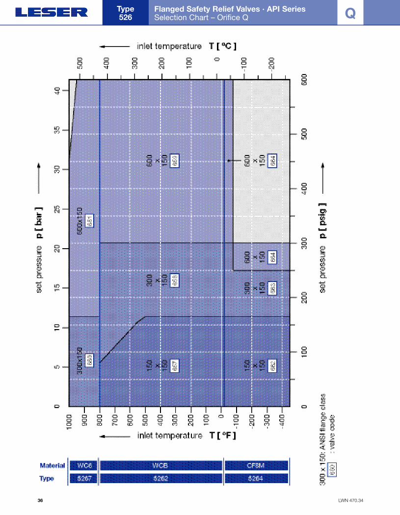
Flanged Safety Relief Valves · API Series Selection Chart – Orifice Q
Type 526
36
Q
Folder API Series 526 NEW 7/13/04 4:40 PM Page 36
LWN 470.35
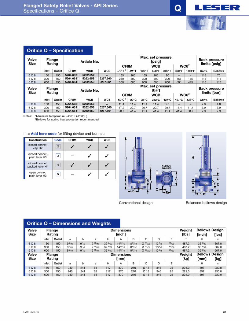
Flanged Safety Relief Valves · API Series Specifications – Orifice Q
37
Q
FlangeRating Article No.
Max. set pressure[psig] Back pressure
limits [psig]ValveSize
Inlet OutletCF8M WCB WC62
150 150 5264.662■ 5262.657■ – 165 165 165 165 80 – – 115 70
CF8M WCB WC6 -76° F1 -21° F 100° F 450° F 800° F 800° F 1000° F Conv. Bellows6 Q 8
300 150 5264.663■ 5262.658■ 5267.660■ 250 300 300 300 300 165 165 115 1156 Q 8600 150 5264.664■ 5262.659■ 5267.661■ 300 600 600 600 600 600 445 115 1156 Q 8
FlangeRating Article No.
Max. set pressure[bar] Back pressure
limits [bar]ValveSize
Inlet OutletCF8M WCB WC62
150 150 5264.662■ 5262.657■ – 11.4 11.4 11.4 11.4 5.5 – – 7.9 4.8
CF8M WCB WC6 -60°C1 -29°C 38°C 232°C 427°C 427°C 538°C Conv. Bellows6 Q 8
300 150 5264.663■ 5262.658■ 5267.660■ 17.2 20.7 20.7 20.7 20.7 11.4 11.4 7.9 7.96 Q 8600 150 5264.664■ 5262.659■ 5267.661■ 20.7 41.4 41.4 41.4 41.4 41.4 30.7 7.9 7.96 Q 8
Orifice Q – Specification
FlangeRating
Dimensions[inch]
Bellows DesignWeight[lbs]
ValveSize
Inlet Outlet150 150 9 7/16
a Hm m
[inch] [lbs]
6 Q 8300 150 9 7/166 Q 8600 150 9 7/166 Q 8
9 1/2b
9 1/29 1/2
2 11/16
s
2 11/16
2 11/16
32 5/32
H
32 5/32
32 5/32
14 9/16
A
14 9/16
14 9/16
8 9/32
B
8 9/32
8 9/32
Ø 23/32
C
Ø 23/32
Ø 23/32
13 5/8D
13 5/813 5/8
31/32 487.2 35 9/32 507.0487.2 35 9/32 507.0487.2 35 9/32 507.0
E
31/3231/32
FlangeRating
Dimensions[mm]
Bellows DesignWeight[kg]
ValveSize
Inlet Outlet150 150 240
a Hm m
[mm] [kg]
6 Q 8300 150 2406 Q 8600 150 2406 Q 8
241
b
241241
68
s
6868
817
H
817817
370
A
370370
210
B
210210
Ø 18
C
Ø 18Ø 18
346
D
346346
25 221.0 897 230.0221.0 897 230.0221.0 897 230.0
E
2525
Conventional design Balanced bellows design
Notes: 1Minimum Temperature: -450° F (-268° C)2Bellows for spring heat protection recommended
Code CF8M WCB WC6
closed bonnet,cap H2
Construction
closed bonnet,plain lever H3
closed bonnet, packed lever H4
open bonnet, plain lever H3
2
3
4
5
✓ ✓ ✓
– ✓ ✓
✓ ✓ ✓
– ✓ ✓
■ = Add here code for lifting device and bonnet:
Orifice Q – Dimensions and Weights
Folder API Series 526 NEW 7/13/04 4:40 PM Page 37
LWN 470.36
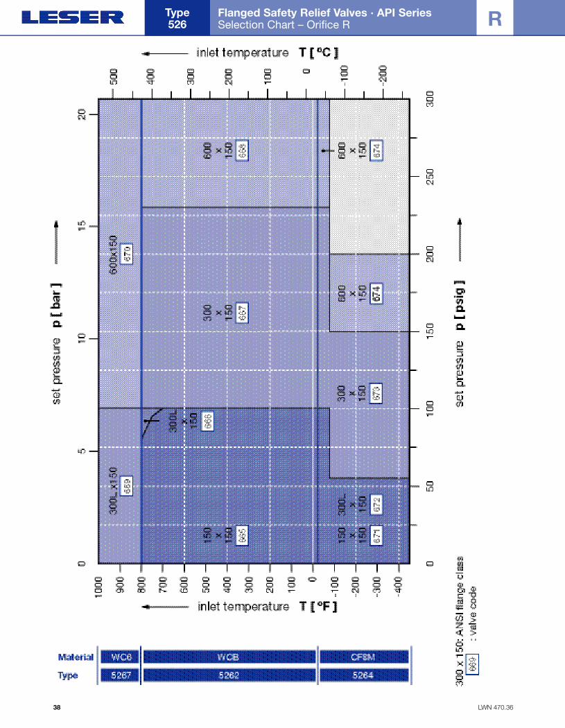
Flanged Safety Relief Valves · API Series Selection Chart – Orifice R
Type 526
38
R
Folder API Series 526 NEW 7/13/04 4:40 PM Page 38

LWN 470.37
Flanged Safety Relief Valves · API Series Specifications – Orifice R
39
R
FlangeRating Article No.
Max. set pressure[psig] Back pressure
limits [psig]ValveSize
Inlet OutletCF8M WCB WC62
150 150 5264.671■ 5262.665■ – 55 100 100 100 80 – – 60 60
CF8M WCB WC6 -76° F1 -21° F 100° F 450° F 800° F 800° F 1000° F Conv. Bellows6 R 8
300L 150 5264.672■ 5262.666■ 5267.669■ 55 100 100 100 100 100 100 60 60
200 300 300 300 300 300 300 100 100
6 R 8300 150 5264.673■ 5262.667■ – 150 230 230 230 230 – – 100 1006 R 10600 150 5264.674■ 5262.668■ 5267.670■6 R 10
FlangeRating Article No.
Max. set pressure[bar] Back pressure
limits [bar]ValveSize
Inlet OutletCF8M WCB WC62
150 150 5264.671■ 5262.665■ – 3.8 6.9 6.9 6.9 5.5 – – 4.1 4.1
CF8M WCB WC6 -60°C1 -29°C 38°C 232°C 427°C 427°C 538°C Conv. Bellows
6 R 8300L 150 5264.672■ 5262.666■ 5267.669■ 3.8 6.9 6.9 6.9 6.9 6.9 6.9 4.1 4.1
13.8 20.7 20.7 20.7 20.7 20.7 20.7 6.9 6.9
6 R 8300 150 5264.673■ 5262.667■ – 10.3 15.9 15.9 15.9 15.9 – – 6.9 6.96 R 10600 150 5264.674■ 5262.668■ 5267.670■6 R 10
Orifice R – Specification
FlangeRating
Dimensions[inch]
Bellows DesignWeight[lbs]
ValveSize
Inlet Outlet150 150 9 7/16
a Hm m
[inch] [lbs]
6 R 8300L 150 9 7/166 R 8300 150 9 7/166 R 10600 150
9 1/2b
9 1/210 1/2
2 11/16
s
2 11/16
2 3/4
32 5/32
H
32 5/32
44 7/32
14 9/16
A
14 9/16
18 1/2
8 9/32
B
8 9/32
5 29/32
Ø 23/32
C
Ø 23/32
Ø 23/32
13 5/8D
13 5/818 1/8
31/32 487.2 35 9/32 507.0487.2 35 9/32 507.0611.0 44 7/32 635.2
E
31/32
9 7/16 10 1/2 2 3/4 44 7/32 18 1/2 5 29/32 Ø 23/32 18 1/8 611.0 44 7/32 635.231/32
31/32
6 R 10FlangeRating
Dimensions[mm]
Bellows DesignWeight[kg]
ValveSize
Inlet Outlet150 150 240
a Hm m[mm] [kg]
6 R 8300L 150 2406 R 8300 150 2406 R 10600 150
241
b
241267
68
s
6870
817
H
8171123
370
A
370470
210
B
210150
Ø 18
C
Ø 18Ø 18
346
D
346460
25 221.0 897.0 230.0221.0 897.0 230.0277.0 1123 288.0
E
25
240 267 70 1123 470 150 Ø 18 460 277.0 1123 288.02525
6 R 10
Conventional design Balanced bellows design
Notes: 1Minimum Temperature: -450° F (-268° C)2Bellows for spring heat protection recommended
Code CF8M WCB WC6
closed bonnet,cap H2
Construction
closed bonnet,plain lever H3
closed bonnet, packed lever H4
open bonnet, plain lever H3
2
3
4
5
✓ ✓ ✓
– ✓ ✓
✓ ✓ ✓
– ✓ ✓
■ = Add here code for lifting device and bonnet:
Orifice R – Dimensions and Weights
Folder API Series 526 NEW 7/13/04 4:40 PM Page 39
LWN 470.38
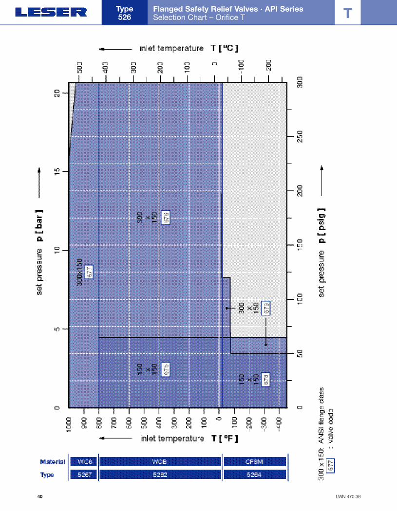
Flanged Safety Relief Valves · API Series Selection Chart – Orifice T
Type 526
40
T
Folder API Series 526 NEW 7/13/04 4:40 PM Page 40
LWN 470.39
Flanged Safety Relief Valves · API Series Specifications – Orifice T
41
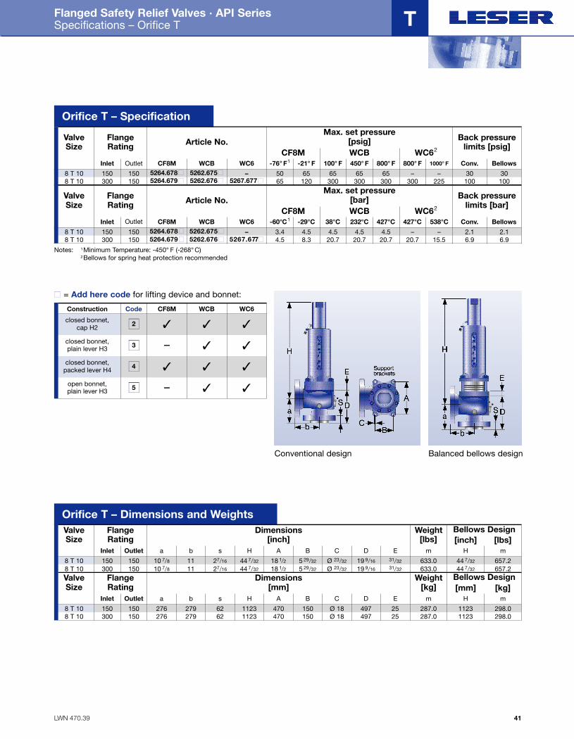
T
FlangeRating Article No.
Max. set pressure[psig] Back pressure
limits [psig]ValveSize
Inlet Outlet
CF8M WCB WC62
150 150 5264.678■ 5262.675■ – 50 65 65 65 65 – – 30 30
CF8M WCB WC6 -76° F1 -21° F 100° F 450° F 800° F 800° F 1000° F Conv. Bellows8 T 10
300 150 5264.679■ 5262.676■ 5267.677■ 65 120 300 300 300 300 225 100 1008 T 10
FlangeRating Article No.
Max. set pressure[bar] Back pressure
limits [bar]ValveSize
Inlet OutletCF8M WCB WC62
150 150 5 2 6 4 . 6 78■ 5 2 6 2 . 6 75■ – 3.4 4.5 4.5 4.5 4.5 – – 2.1 2.1
CF8M WCB WC6 -60°C1 -29°C 38°C 232°C 427°C 427°C 538°C Conv. Bellows8 T 10
300 150 5 2 6 4 . 6 79■ 5 2 6 2 . 6 76■ 5 2 6 7 . 6 77■ 4.5 8.3 20.7 20.7 20.7 20.7 15.5 6.9 6.98 T 10
Orifice T – Specification
FlangeRating
Dimensions[inch]
Bellows DesignWeight[lbs]
ValveSize
Inlet Outlet150 150 10 7/8
a Hm m
[inch] [lbs]
8 T 10300 150 10 7/88 T 10
11
b
1127/16
s
27/16
44 7/32
H
44 7/32
18 1/2A
18 1/25 29/32
B
5 29/32
Ø 23/32
C
Ø 23/32
19 9/16
D
19 9/16
31/32 633.0 44 7/32 657.2633.0 44 7/32 657.2
E
31/32
FlangeRating
Dimensions[mm]
Bellows DesignWeight[kg]
ValveSize
Inlet Outlet150 150 276
a Hm m
[mm] [kg]
8 T 10300 150 2768 T 10
279
b
27962
s
621123
H
1123470
A
470150
B
150Ø 18
C
Ø 18497
D
49725 287.0 1123 298.0
287.0 1123 298.0
E
25
Conventional design Balanced bellows design
Code CF8M WCB WC6
closed bonnet,cap H2
Construction
closed bonnet,plain lever H3
closed bonnet, packed lever H4
open bonnet, plain lever H3
2
3
4
5
✓ ✓ ✓
– ✓ ✓
✓ ✓ ✓
– ✓ ✓
■ = Add here code for lifting device and bonnet:
Notes: 1Minimum Temperature: -450° F (-268° C)2Bellows for spring heat protection recommended
Orifice T – Dimensions and Weights
Folder API Series 526 NEW 7/13/04 4:40 PM Page 41
LWN 470.40
Flanged Safety Relief Valves · API Series Accessories and Options · Caps and Levers
Type 526
42
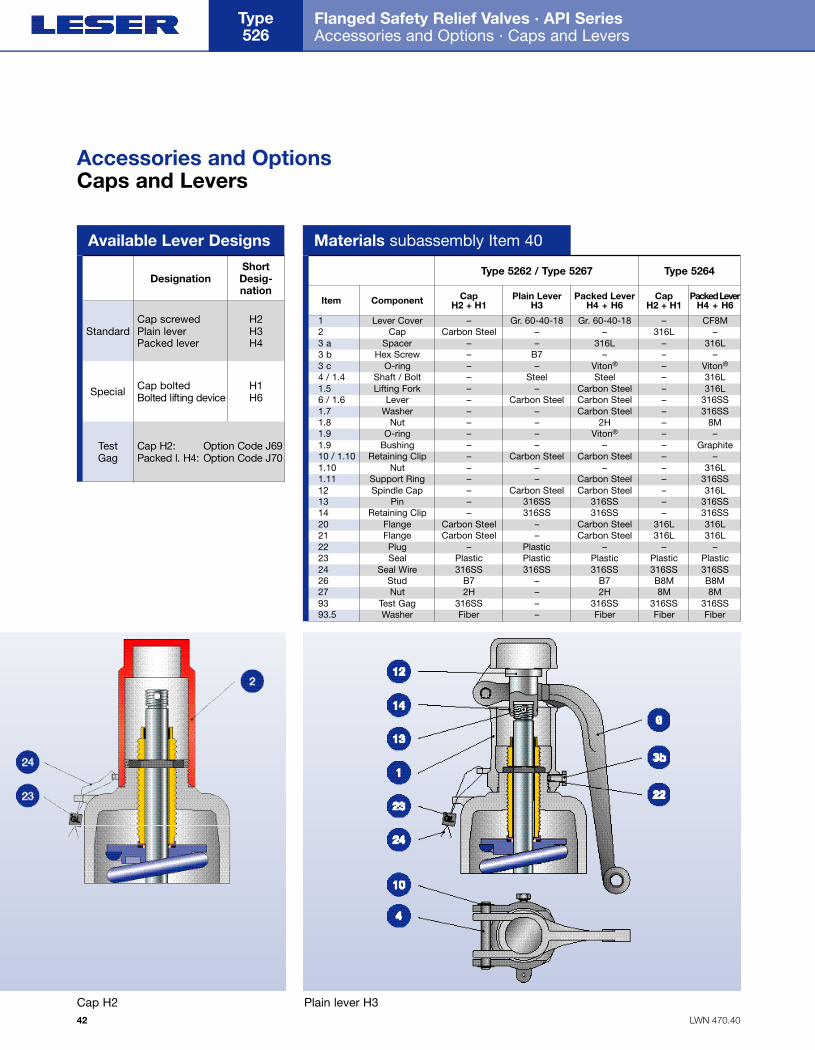
Type 5262 / Type 5267
Lever Cover
Type 5264
1
Component
–
Cap H2 + H1
Gr. 60-40-18
Plain Lever H3
Gr. 60-40-18
Packed Lever H4 + H6
–
Cap H2 + H1
CF8MCap2 Carbon Steel – – 316L –
Spacer3 a – – 316L – 316LHex Screw3 b – B7 – – –
O-ring3 c – – Viton® – Viton®
Shaft / Bolt4 / 1.4 – Steel Steel – 316LLifting Fork1.5 – – Carbon Steel – 316L
Lever6 / 1.6 – Carbon Steel Carbon Steel – 316SSWasher1.7 – – Carbon Steel – 316SS
Nut1.8 – – 2H – 8MO-ring1.9 – – Viton® – –
Bushing1.9 – – – – GraphiteRetaining Clip10 / 1.10 – Carbon Steel Carbon Steel – –
Nut1.10 – – – – 316LSupport Ring1.11 – – Carbon Steel – 316SSSpindle Cap12 – Carbon Steel Carbon Steel – 316L
Pin13 – 316SS 316SS – 316SSRetaining Clip14 – 316SS 316SS – 316SS
Flange20 Carbon Steel – Carbon Steel 316L 316LFlange21 Carbon Steel – Carbon Steel 316L 316LPlug22 – Plastic – – –Seal23 Plastic Plastic Plastic Plastic Plastic
Seal Wire24 316SS 316SS 316SS 316SS 316SSStud26 B7 – B7 B8M B8MNut27 2H – 2H 8M 8M
Test Gag93 316SS – 316SS 316SS 316SSWasher93.5 Fiber – Fiber Fiber Fiber
Packed LeverH4 + H6Item
Materials subassembly Item 40
Accessories and OptionsCaps and Levers
Cap H2 Plain lever H3
StandardCap screwedPlain leverPacked lever
H2H3H4
Special Cap boltedBolted lifting device
H1H6
Test Gag
Cap H2: Option Code J69Packed l. H4: Option Code J70
DesignationShortDesig-nation
Available Lever Designs
Folder API Series 526 NEW 7/13/04 4:41 PM Page 42
LWN 470.41
Flanged Safety Relief Valves · API Series Accessories and Options · Caps and Levers
43
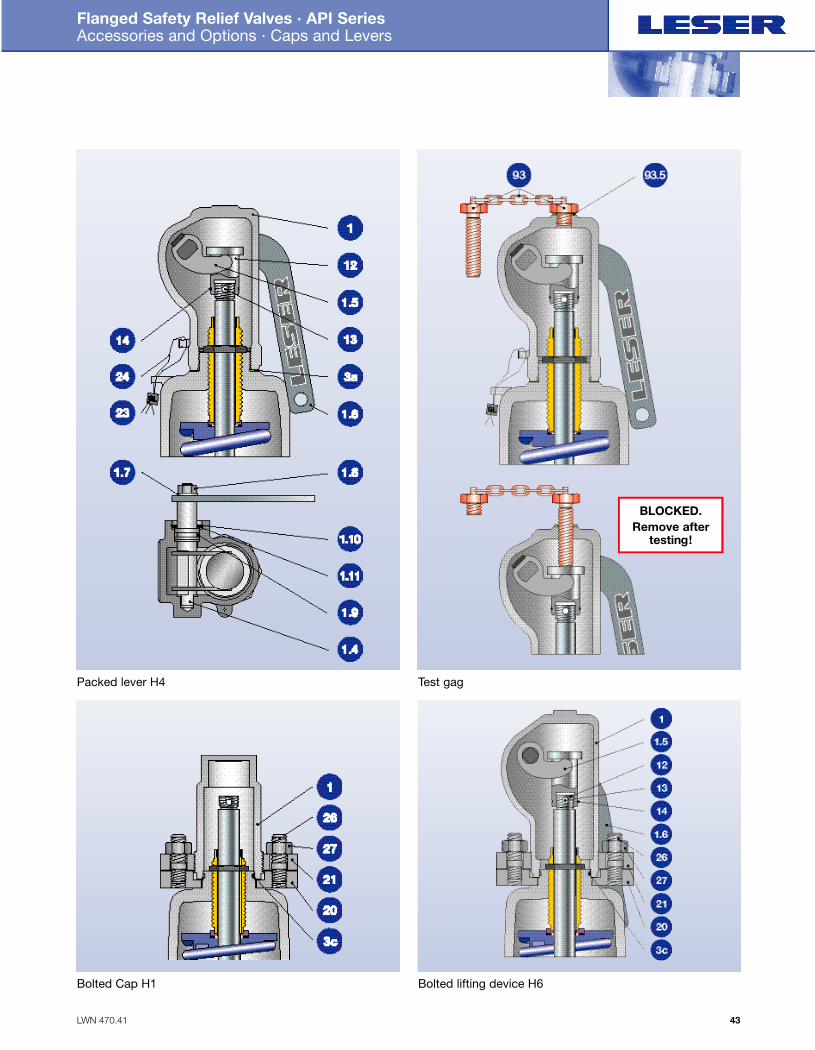
Packed lever H4 Test gag
Bolted Cap H1 Bolted lifting device H6
BLOCKED.Remove after
testing!
Folder API Series 526 NEW 7/13/04 4:41 PM Page 43
LWN 470.42
Flanged Safety Relief Valves · API Series Accessories and Options · Balanced Bellows
Type 526
44
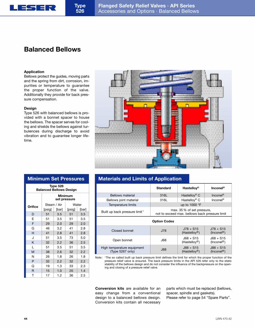
ApplicationBellows protect the guides, moving part sand the spring from dirt, corrosion, im-purities or temperature to guaranteethe proper function of the valve.Additionally they provide for back pres-sure compensation.
DesignType 526 with balanced bellows is pro-vided with a bonnet spacer to housethe bellows. The spacer serves for cool-ing and shields the bellows against tur-bulences during discharge to avoidvibration and to guarantee longer life-time.
Materials and Limits of Application
Bellows materialBellows joint material
Temperature limits
Built up back pressure limit 1
Option Codes
Closed bonnet
Open bonnet
High temperature equipment(Type 5267 only)
316L
Standard
316Lup to 1000 °F
max. 35 % of set pressure, not to exceed max. bellows back pressure limit
J78 J78 + S15(Hastelloy®)
J78 + S15(Inconel®)
J68 J68 + S15(Hastelloy®)
J68 + S15(Inconel®)
J88 J88 + S15(Hastelloy®)
J88 + S15(Inconel®)
Hastelloy® C
Hastelloy®
Hastelloy® CInconel®
Inconel®
Inconel®
Conversion kits are available for aneasy change from a conventionaldesign to a balanced bellows design.Conversion kits contain all necessary
parts which must be replaced (bellows,spacer, spindle and gaskets). Please refer to page 54 “Spare Parts”.
D 51 51E 51 51F 29 29G 46 41H 41 41J 51 73K 32 36L 51 51M 38 32N 26 26P 32 32Q 19 33R 15 20T 17
3.53.52.03.22.83.52.23.52.61.82.21.31.01.2 36
3.53.52.02.82.85.02.53.52.21.82.22.31.42.5
Orifice Steam / Air[psig] [bar] [psig] [bar]
Minimum set pressure
Water
Minimum Set PressuresType 526
Balanced Bellows Design
Note: 1The so called built up back pressure limit defines the limit for which the proper function of thepressure relief valve is ensured. The back pressure limits in the API 526 refer only to the static stability of the bellows design and do not consider the influence of the backpressure on the open-ing and closing of a pressure relief valve.
Balanced Bellows
Folder API Series 526 NEW 7/13/04 4:41 PM Page 44
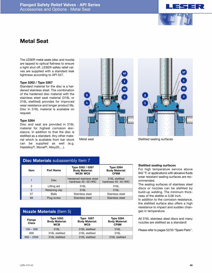
Stellited sealing surfacesFor high temperature service above842 °F, or applications with abrasive fluidswear resistant sealing surfaces are rec-ommended.The sealing surfaces of stainless steeldiscs or nozzles can be stellited bybuild-up welding. The minimum thick-ness of the stellite is 0,06 inch.In addition to the corrosion resistance,the stellited surface also offers a highresistance to impact and sudden chan-ges in temperature.
All 316L stainless steel discs and manynozzles are stellited as a standard!
Please refer to pages 52/53 “Spare Part s ” .
LWN 470.43
Flanged Safety Relief Valves · API Series Accessories and Options · Metal Seat
45
66
Disc Materials subassembly Item 7
1
Item
2357
Disc
Part Name
Lifting aidRetaining clip 316L 316L
BallsPlug screw
Stainless steelStainless steel
Stainless steelStainless steel
Hardened stainless steelhardness 40 - 50 HRC
Type 5262 / 5267Body Material:
WCB/ WC6
316L
316L stellitedhardness 40 - 45 HRC
Type 5264Body Material:
CF8M
316L
Nozzle Materials (Item 5)
150 – 300
Flange Class
600900 – 2500
316L
Type 5262Body Material:
WCB
316L stellited316L stellited 316L stellited
316L stellited316L stellited316L stellited
Type 5267Body Material:
WC6
316L
Type 5264Body Material:
CF8M
316L
The LESER metal seats (disc and nozzle)are lapped to optical flatness to ensurea tight shut off. LESER safety relief val-ves are supplied with a standard leaktightness according to API 527.
Type 5262 / Type 5267Standard material for the disc is a har-dened stainless steel. The combinationof the hardened disc material with thestainless steel seat material (316L or316L stellited) provides for improvedwear resistance and longer product life.Disc in 316L material is available onrequest.
Type 5264Disc and seat are provided in 316Lmaterial for highest corrosion re s i -stance. In addition to that the disc isstellited as a standard. Any other mate-rial which is available from bar stockcan be supplied as well (e.g.Hastelloy®, Monel®, Alloy20,…).
Metal seat Stellited sealing surfaces
Metal Seat
Folder API Series 526 NEW 7/13/04 4:41 PM Page 45
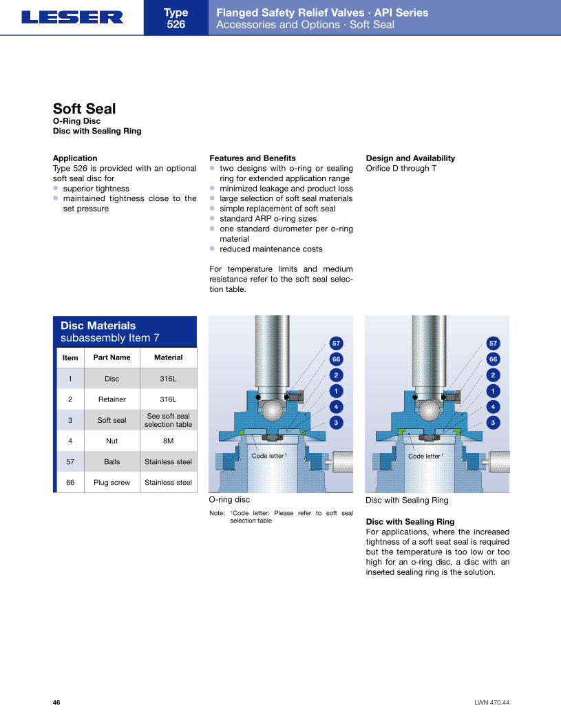
ApplicationType 526 is provided with an optionalsoft seal disc for● superior tightness● maintained tightness close to the
set pressure
Features and Benefits● two designs with o-ring or sealing
ring for extended application range● minimized leakage and product loss● large selection of soft seal materials● simple replacement of soft seal● standard ARP o-ring sizes● one standard durometer per o-ring
material● reduced maintenance costs
For temperature limits and mediumresistance refer to the soft seal selec-tion table.
Design and Availability1Orifice D through T
Disc with Sealing RingFor applications, where the increasedtightness of a soft seat seal is requiredbut the temperature is too low or toohigh for an o-ring disc, a disc with ani n s e rt e d sealing ring is the solution.
LWN 470.44
Flanged Safety Relief Valves · API Series Accessories and Options · Soft Seal
Type 526
46
O-ring disc Disc with Sealing Ring
Code letter 1 Code letter 1
66
Disc Materials subassembly Item 7
1
Item
2
3
57
Disc
Part Name
Retainer
Soft seal See soft seal selection table
4 Nut 8M
Balls
Plug screw
Stainless steel
Stainless steel
316L
Material
316L
Soft SealO-Ring DiscDisc with Sealing Ring
Note: 1Code letter: Please refer to soft sealselection table
Folder API Series 526 NEW 7/13/04 4:41 PM Page 46

LWN 470.45
Flanged Safety Relief Valves · API Series Accessories and Options · Soft Seal Selection
47
D 1480 1024 0.3
4
4
4
4
4
4
4
4
4
4
4
4
4
0.3
0.3
0.3
0.3
0.3
0.3
0.3
0.3
0.3
0.3
0.3
0.3
0.3
1480 102
1480 102
1480 102
1480 102
1480 102
1480 102
1100 75.8
1100 75.8
1000 68.9
1000 68.9
600 41.3
300 20.6
300 20.6
E
F
G
H
J
K
L
M
N
P
Q
R
T
Orifice[psig]
Set Pressuremax.min.
[bar][psig] [bar] [psig]max.min.
[bar][psig] [bar]
Abbre-vationASTM1418
DesignationTrade name
Code-letter1
OptionCode
[°F] [°F]Application2
MaterialPressure Range
VESPEL SP-1® 150
Kel-F® 15
Teflon® 15
10
1
1
5800
4350
145
400
300
10
Size
D – G
D – T
D – T
J49
J48
J44
T
G
A
VESPEL SP-1® 3
(Polyimide)
Kel-F®
(Polychlorotri-fluoroethylene)
Teflon®
( P o l y t e t r a f l u o ro e t h y l e n e )
SP
PCTFE
PTFE
-454
-454
-300
572
400
302
High temperature and high pressure applications (no steam), for chemical resistance refer to manufacturers guide
Cryogenic and refrigeration application, flammable media, gaseous oxygene application up to 725 psig at 140 ºF
Nearly all chemicals
CR Neoprene®
(Chloroprene) K J21 -40 212 Paraffin oil, silicone oil and grease, water and waterbased solvents, refrigerants, ozone
NBR Buna - N®
(Nitrile-Butadiene) N J30 -13 230 Hydraulic oil, vegetable and animal grease and oil
EPDMBuna - EP®
(Ethylene-Propylene -Diene)
D J22 -49 302Hot water and superheated steam up to 302°F,several organic and inorganic acids, silicone oil and grease, FDA compliant
FPM(FKM)
Viton®
(Fluorocarbon) L J23 -4 356
For high temperature service (no superheated steam),mineral oil and grease, silicone oil and grease, vege-table and animal grease and oil, ozone, FDA compliantcompound available on request
FFKM Kalrez®
(Perfluoro)
Other Please contact factory
C J20 32
[°C]
-270
-270
-184
-40
-25
-45
-20
0 482
[°C]
300
204
150
100
110
150
180
250Nearly all chemicals, standard compound is Kalrez® 6375 with steam resistance, FDA compliantcompound available on request
Soft Seal Selection
Set Pressure LimitsO-ring disc
Notes: 1 The code letters will be stamped on the retainer (Item 2). For soft seal materials other than listed the code letter X will be used.2 P re s s u re and temperature service must be considered in any case. Chemical resistance depends on O-ring manufacturer information. LESER can not take any warr a n t y.3 Up to orifice G only.
Set Pressure and Size LimitsSealing ring disc
Buna-N®, Teflon®,Viton®, VESPEL SP-1®,Neoprene®, Kalrez®
DuPont
Bayer
3M
Buna EP®
Kel-F®
Registered Trademarks Company
TmaxTmin
ConversionIt is possible to change a standard discinto a soft seal design easily withoutchanging any other part of the valve(single trim and same spring table).Please refer to page 52/53 Spare Parts.
Folder API Series 526 NEW 7/13/04 4:41 PM Page 47
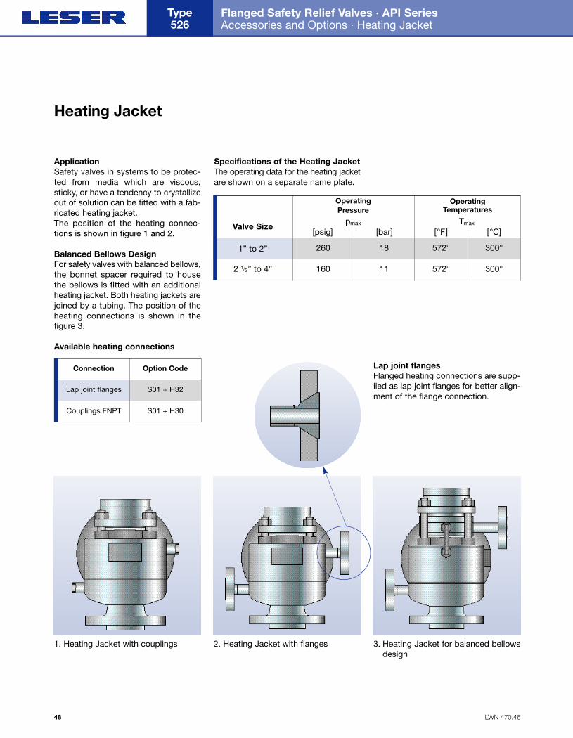
ApplicationSafety valves in systems to be protec-ted from media which are viscous,sticky, or have a tendency to crystallizeout of solution can be fitted with a fab-ricated heating jacket.The position of the heating connec-tions is shown in figure 1 and 2.
Balanced Bellows DesignFor safety valves with balanced bellows,the bonnet spacer required to housethe bellows is fitted with an additionalheating jacket. Both heating jackets arejoined by a tubing. The position of theheating connections is shown in thefigure 3.
Available heating connections
Specifications of the Heating JacketThe operating data for the heating jacketare shown on a separate name plate.
LWN 470.46
Flanged Safety Relief Valves · API Series Accessories and Options · Heating Jacket
Type 526
48
Operating Pressure
pmax Tmax
[psig] [bar]Valve Size
2601” to 2”
160
18
112 1/2” to 4”
Operating Temperatures
[°F] [°C]
572°
572°
300°
300°
2. Heating Jacket with flanges1. Heating Jacket with couplings 3. Heating Jacket for balanced bellowsdesign
Connection Option Code
S01 + H32Lap joint flanges
S01 + H30Couplings FNPT
Heating Jacket
Lap joint flangesFlanged heating connections are supp-lied as lap joint flanges for better align-ment of the flange connection.
Folder API Series 526 NEW 7/13/04 4:41 PM Page 48
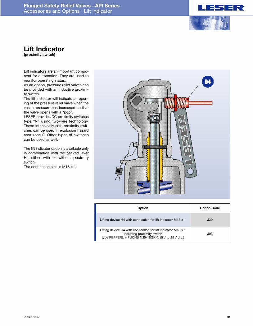
Lift indicators are an important compo-nent for automation. They are used tomonitor operating status.As an option, pressure relief valves canbe provided with an inductive proximi-ty switch. The lift indicator will indicate an open-ing of the pressure relief valve when thevessel pressure has increased so thatthe valve opens with a “pop”.LESER provides DC proximity switchestype “N” using two-wire technology.These intrinsically safe proximity swit-ches can be used in explosion hazardarea zone 0. Other types of switchescan be used as well.
The lift indicator option is available onlyin combination with the packed leverH4 either with or without pro x i m i t yswitch.The connection size is M18 x 1.
LWN 470.47
Flanged Safety Relief Valves · API Series Accessories and Options · Lift Indicator
49
Option Option Code
J39Lifting device H4 with connection for lift indicator M18 x 1
J93Lifting device H4 with connection for lift indicator M18 x 1
including proximity switchtype PEPPERL + FUCHS NJ5-18GK-N (5 V to 25 V d.c.)
Lift Indicator (proximity switch)
Folder API Series 526 NEW 7/13/04 4:41 PM Page 49
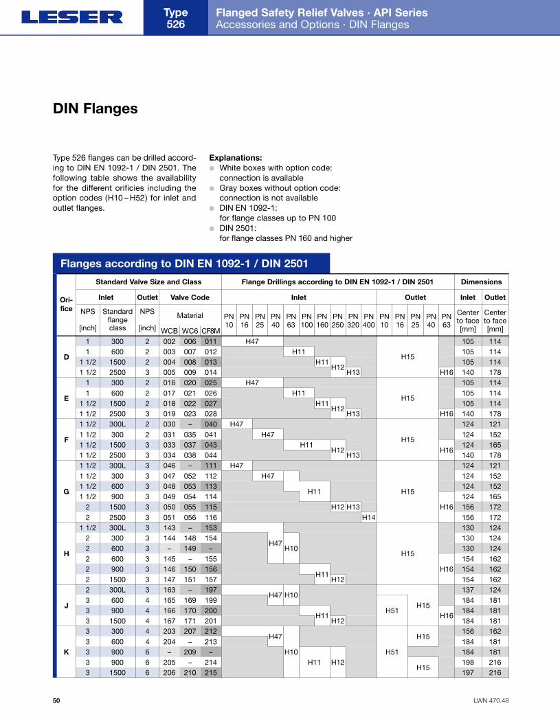
LWN 470.48
Flanged Safety Relief Valves · API Series Accessories and Options · DIN Flanges
Type 526
50
O r i -f i c e NPS
[inch]
Standardflange class
NPS
[inch]
23001
D
E
F
G
H
J
K
Inlet
Standard Valve Size and Class Flange Drillings according to DIN EN 1092-1 / DIN 2501 Dimensions
O u t l e t
Material PN10
WCB002 H47
H15
H15
H15
H15
H15
H15
H15
H15
H51
H51
105 114
PN16
PN25
PN40
PN63
PN100
PN160
PN250
PN320
PN400
PN10
PN16
PN25
PN40
PN63
Centerto face[mm]
Centerto face[mm]WC6
006C F 8 M011
26001 003 H11 105 114007 012215001 1/2 004 H11
H12105 114008 013
325001 1/2 005 H13 H16 140 178009 014016 020 025017 021 026018 022 027019 023 028030 – 040031 035 041033 037 043034 038 044046 – 111047 052 112048 053 113049 054 114050 055 115051 056 116143 – 153144 148 154
– 149 –145 – 155146 150 156147 151 157163 – 197165 169 199166 170 200167 171 201203 207 212204 – 213
– 209 –205 – 214206 210 215
23001 H47 105 11426001 H11 105 114215001 1/2 H11
H12105 114
325001 1/2 H13 H16 140 1782300L1 1/2 H47 124 12123001 1/2 H47 124 152315001 1/2 H11
H12 H16124 165
325001 1/2 H13 140 1783300L1 1/2 H47 124 12133001 1/2 H47 124 15236001 1/2
H11124 152
39001 1/2 124 165315002 H12 H13 H16 156 172325002 H14 156 1723300L1 1/2 130 12433002
H47H10
130 1243600
6002 130 124
32 154 16239002
H11H16 154 162
315002 H12 154 1623300L2
H47 H10137 124
46003 184 18149003
H11 H16184 181
415003 H12 184 18143003
H47
H10
156 16246003 184 1816900
9003
H11 H12184 181
63 198 216615003 197 216
Valve Code Inlet Outlet Inlet Outlet
Flanges according to DIN EN 1092-1 / DIN 2501
Type 526 flanges can be drilled accord-ing to DIN EN 1092-1 / DIN 2501. Thefollowing table shows the availabilityfor the different orificies including theoption codes (H10 – H52) for inlet andoutlet flanges.
Explanations:● White boxes with option code:
connection is available● Gray boxes without option code:
connection is not available● DIN EN 1092-1:
for flange classes up to PN 100● DIN 2501:
for flange classes PN 160 and higher
DIN Flanges
Folder API Series 526 NEW 7/13/04 4:41 PM Page 50
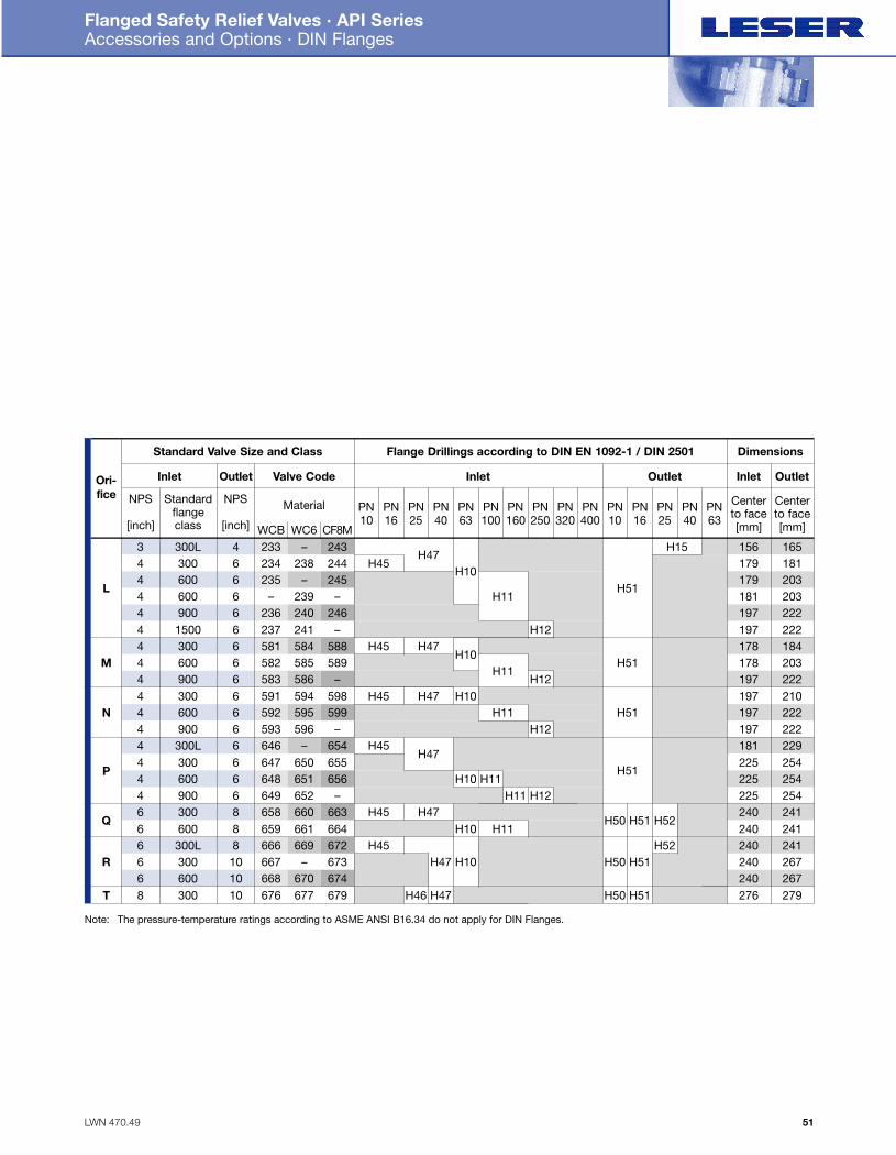
H10
LWN 470.49
Flanged Safety Relief Valves · API Series Accessories and Options · DIN Flanges
51
O r i -f i c e NPS
[inch]
Standardflange class
NPS
[inch]
4300L3
L
M
N
P
Q
R
T
Inlet
Standard Valve Size and Class Flange Drillings according to DIN EN 1092-1 / DIN 2501 Dimensions
O u t l e t
Material PN10
WCB233
H47
H51
H51
H51
H51
H50
H50 H51
H50 H51
H52
H51 H52
H15 156 165
PN16
PN25
PN40
PN63
PN100
PN160
PN250
PN320
PN400
PN10
PN16
PN25
PN40
PN63
Centerto face[mm]
Centerto face[mm]WC6
–C F 8 M243
63004 234 H45H10
179 181238 24466004 235
H11179 203– 245
66004 – 181 203239 –236 240 246237 241 –581 584 588582 585 589583 586 –591 594 598592 595 599593 596 –646 – 654647 650 655648 651 656649 652 –658 660 663659 661 664666 669 672667 – 673668 670 674676 677 679
69004 197 222615004 H12 197 22263004 H45 H47 178 18466004
H11H12
178 20369004 197 22263004 H45 H47 H10 197 21066004 H11
H12197 222
69004 197 2226300L4 H45
H47181 229
63004H10
225 25466004 H11 225 25469004 H11 H12 225 25483006 H45 H47 240 24186006 H10 H11 240 2418300L6 H45 240 241103006 H47 H10 240 26710600
3006 240 267
108 H46 H47 276 279
Valve Code Inlet Outlet Inlet Outlet
Note: The pressure-temperature ratings according to ASME ANSI B16.34 do not apply for DIN Flanges.
Folder API Series 526 NEW 7/13/04 4:41 PM Page 51
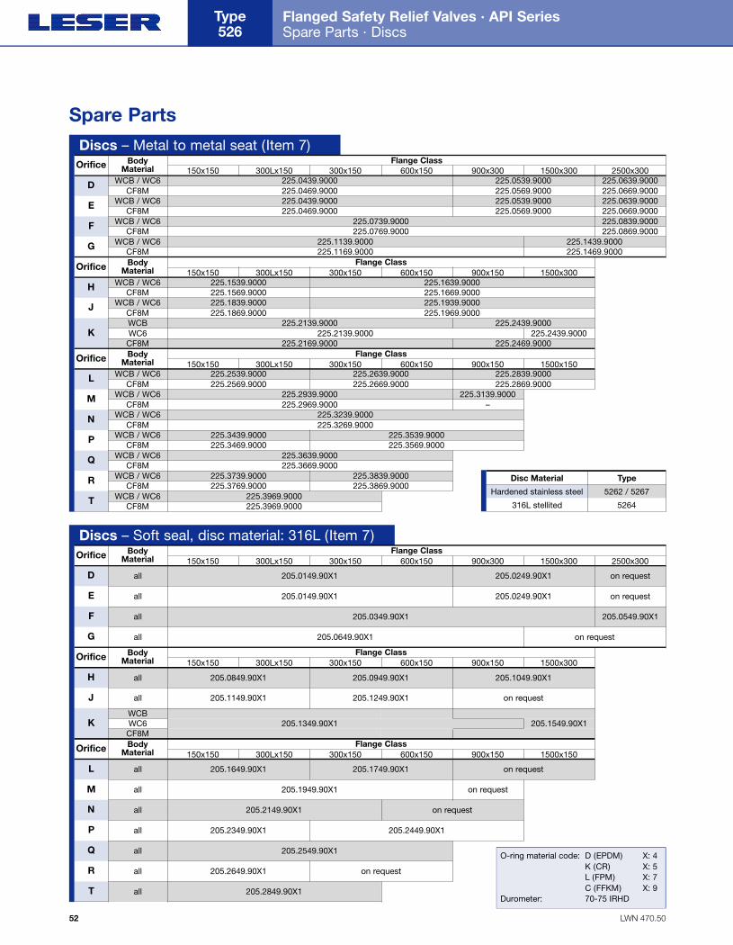
Type
LWN 470.50
Flanged Safety Relief Valves · API Series Spare Parts · Discs
Type 526
52
Discs – Metal to metal seat (Item 7)
Spare Parts
Orifice BodyMaterial
D WCB / WC6 225.0439.9000 225.0539.9000 225.0639.9000225.0469.9000 225.0569.9000 225.0669.9000225.0439.9000 225.0539.9000 225.0639.9000225.0469.9000 225.0569.9000 225.0669.9000
225.0739.9000 225.0839.9000225.0769.9000 225.0869.9000
225.1139.9000 225.1439.9000225.1169.9000 225.1469.9000
CF8M
E WCB / WC6CF8M
F WCB / WC6CF8M
G WCB / WC6CF8M
1500x300900x300600x150300x150300Lx150150x150Flange Class
2500x300
Orifice BodyMaterial
H WCB / WC6 225.1539.9000 225.1639.9000225.1569.9000 225.1669.9000225.1839.9000 225.1939.9000225.1869.9000 225.1969.9000
225.2139.9000225.2139.9000 225.2439.9000
225.2469.9000
225.2439.9000
225.2169.9000
CF8M
J WCB / WC6CF8M
KWCBWC6CF8M
1500x300900x150600x150300x150300Lx150150x150Flange Class
Orifice BodyMaterial
L WCB / WC6 225.2539.9000 225.2639.9000225.2569.9000 225.2669.9000
225.2839.9000225.2869.9000
225.2939.9000 225.3139.9000225.2969.9000 –
CF8M
M WCB / WC6CF8M
1500x150900x150600x150300x150300Lx150150x150Flange Class
225.3239.9000225.3269.9000
N WCB / WC6CF8M
225.3439.9000 225.3539.9000225.3469.9000 225.3569.9000
P WCB / WC6CF8M
225.3639.9000225.3669.9000
Q WCB / WC6CF8M
225.3739.9000 225.3839.9000225.3769.9000 225.3869.9000
R WCB / WC6CF8M
225.3969.9000225.3969.9000
T WCB / WC6CF8M
Discs – Soft seal, disc material: 316L (Item 7)Orifice Body
Material
D all
all
all
all
205.0149.90X1 205.0249.90X1 on request
205.0149.90X1 205.0249.90X1 on request
205.0349.90X1 205.0549.90X1
205.0649.90X1 on request
E
F
G
1500x300900x300600x150300x150300Lx150150x150Flange Class
2500x300
Orifice BodyMaterial
H 205.0849.90X1 205.0949.90X1 205.1049.90X1
205.1149.90X1 205.1249.90X1 on request
205.1349.90X1 205.1549.90X1
J
KWCBWC6CF8M
1500x300900x150600x150300x150300Lx150150x150Flange Class
Orifice BodyMaterial
L 205.1649.90X1 205.1749.90X1 on request
205.1949.90X1 on requestM
1500x150900x150600x150300x150300Lx150150x150Flange Class
205.2149.90X1 on requestN
205.2349.90X1 205.2449.90X1P
205.2549.90X1Q
205.2649.90X1 on requestR
205.2849.90X1T
O-ring material code: D (EPDM) X: 4K (CR) X: 5L (FPM) X: 7C (FFKM) X: 9
Durometer: 70-75 IRHD
Disc Material
5262 / 5267Hardened stainless steel
5264316L stellited
all
all
all
all
all
all
all
all
all
Folder API Series 526 NEW 7/13/04 4:41 PM Page 52

LWN 470.51
Flanged Safety Relief Valves · API Series Spare Parts · O-Rings · Nozzles
53
O-Rings – Soft seal seat (Item 7.3)Orifice Body
Material
D all
all
all
all
all
all
all
all
all
all
all
all
all
all
502.0171.26X1 ARP 115 0.674 x 0.103
502.0171.26X1 ARP 115 0.674 x 0.103
502.0202.26X1 ARP 117 0.799 x 0.103
502.0249.35X1 ARP 214 0.984 x 0.139
E
F
G
1500x300900x300600x150300x150300Lx150150x150Flange Class
2500x300
Orifice BodyMaterial
H 502.0313.35X1 ARP 218 1.234 x 0.139
502.0408.35X1 ARP 223 1.609 x 0.139
502.0472.35X1 ARP 225 1.859 x 0.139
J
K
1500x300900x150600x150300x150300Lx150150x150Flange Class
Orifice BodyMaterial
L 502.0567.35X1 ARP 228 2.234 x 0.139
502.0628.53X1 ARP 333 2.475 x 0.210
502.0692.53X1 ARP 335 2.725 x 0.210
502.0850.53X1 ARP 340 3.350 x 0.210
502.1104.53X1 ARP 348 4.350 x 0.210
502.1327.53X1 ARP 355 5.225 x 0.210
502.1664.53X1 ARP 363 6.475 x 0.210
M
1500x150900x150600x150300x150300Lx150150x150Flange Class
N
P
Q
R
T
O-ring material code: D (EPDM) X: 4K (CR) X: 5L (FPM) X: 7C (FFKM) X: 9
Durometer: 70-75 IRHD
Nozzles – material: 316L (Item 5)Orifice Body
Material
BodyMaterial
D
E
F
G
H
J
K
L
M
N
P
Q
R
T
WCBWC6CF8M
207.2049.9000 207.2069.9000 207.2269.9000 207.2769.9000
WCBWC6CF8M
207.2349.9000 207.2369.9000 207.2869.9000
WCBWC6CF8M
207.2049.9000 207.2069.9000 207.2269.9000 207.2769.9000
WCBWC6
CF 8M
WCB / CF8MWC6
WCB/WC6/CF8M
WCB/WC6/CF8M
WCB/WC6/CF8M
WCB/WC6/CF8M
207.2449.9000
207.2549.9000
207.3049.9000 207.3569.9000
207.2949.9000207.3169.9000207.2969.9000
WCB / CF8MWC6
207.3349.9000 207.4169.9000207.3669.9000
207.4269.9000207.3369.9000
WCB / CF8MWC6
207.3449.9000
207.3869.9000
207.4069.9000
207.4669.9000207.4569.9000
WCB/WC6/CF8M
207.4769.9000
WCB / CF8MWC6
WCB / CF8MWC6
207.4869.9000
207.5969.9000
207.5769.9000
207.3969.9000207.4369.9000
207.4469.9000
207.3769.9000
207.2469.9000 207.3269.9000
1500x300900x300600x150300x150300Lx150150x150Flange Class
1500x300900x150600x150300x150300Lx150150x150Flange Class
2500x300
All highlighted nozzles arestellited additionally as astandard.
Orifice
BodyMaterial 1500x150900x150600x150300x150300Lx150150x150
Flange ClassOrifice
= stellited207.2069.9000
Folder API Series 526 NEW 7/13/04 4:41 PM Page 53
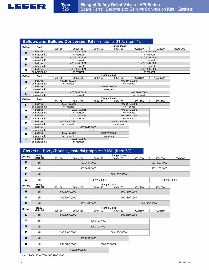
LWN 470.52
Flanged Safety Relief Valves · API Series Spare Parts · Bellows and Bellows Conversion Kits · Gaskets
Type 526
54
Bellows and Bellows Conversion Kits – material 316L (Item 15)Orifice Part
D bellows 400.8349.0021 400.8349.0000on request on request
400.8349.0021 400.8349.0000on request on request
400.8449.0021 400.8449.0000on request on request
conversion kitbellows
conversion kitbellows
conversion kitbellows
conversion kit
bellowsconversion kit
bellowsconversion kit
bellowsconversion kit
bellowsconversion kit
bellowsconversion kit
bellowsconversion kit
bellowsconversion kit
bellowsconversion kit
bellowsconversion kit
bellowsconversion kit
E
F
G
1500x300900x300600x150300x150300Lx150150x150Flange Class
2500x300
400.8549.0021 400.8549.0000on request on request
Orifice Part
H 400.8549.0021 400.8749.0000on request on request
400.8849.0000on request
400.8949.0021 400.8949.0000on request on request
J
K
1500x300900x150600x150300x150300Lx150150x150Flange Class
Orifice Part
L 400.9049.0000 400.9149.0000on request on request
400.9249.0021 400.9249.0000on request on request
400.9349.0021 400.9349.0000on request on request
M
1500x150900x150600x150300x150300Lx150150x150Flange Class
400.9449.0000 400.9549.0000on request on request
400.9649.0000on request
400.9749.0021on request
400.9849.0000on request
400.9749.0000on request
N
P
Q
R
T
Gaskets – body / bonnet, material graphite / 316L (Item 60)Orifice Body
Material
D all 500.0807.0000 500.1207.0000
500.0807.0000 500.1207.0000
500.1207.0000
500.1207.0000 500.1607.0000
all
all
all
all
all
all
all
all
all
all
all
all
all
E
F
G
1500x300900x300600x150300x150300Lx150150x150Flange Class
2500x300
Orifice BodyMaterial
H 500.1207.0000 500.1607.0000
500.1607.0000 500.1907.0000
500.1907.0000 500.2107.00001
J
K
1500x300900x150600x150300x150300Lx150150x150Flange Class
Orifice BodyMaterial
L 500.1907.0000
500.2107.0000
500.2107.0000
500.2107.0000
500.2207.0000
500.2207.0000
500.2807.0000
500.2807.0000
500.2207.0000
500.2107.0000
M
1500x150900x150600x150300x150300Lx150150x150Flange Class
N
P
Q
R
T
Note: 1 900x150 in WC6: 500.1907.0000
Folder API Series 526 NEW 7/13/04 4:41 PM Page 54
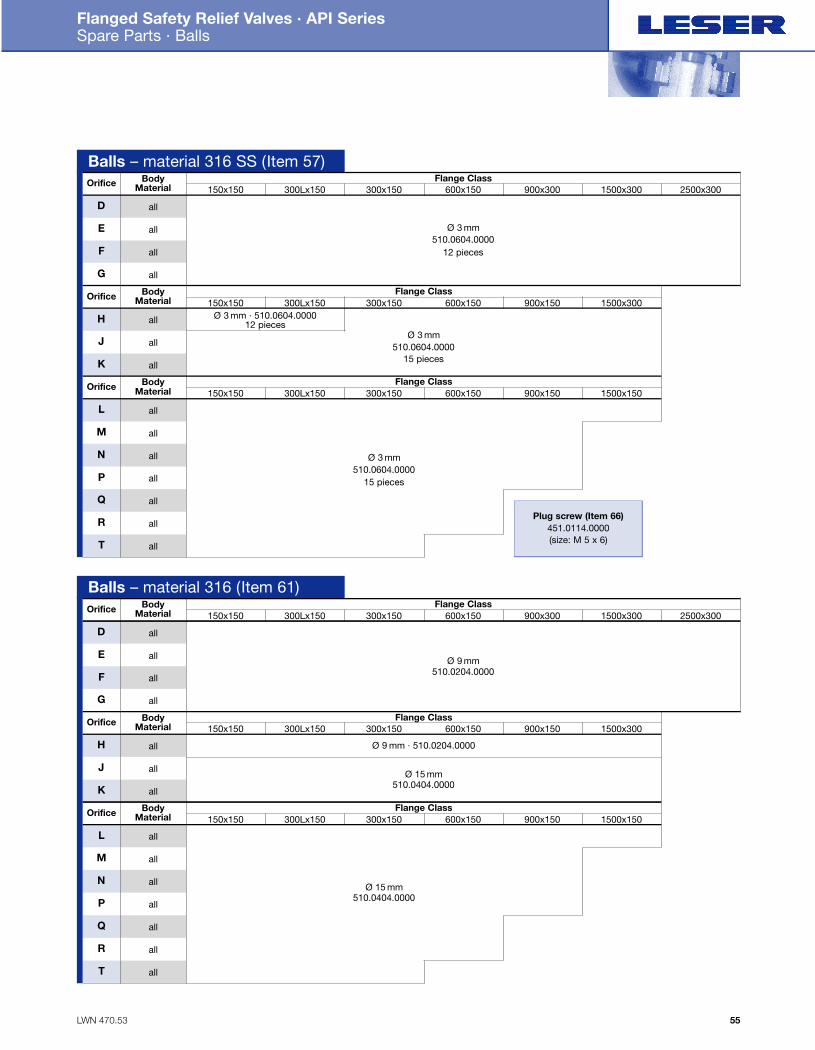
LWN 470.53
Flanged Safety Relief Valves · API Series Spare Parts · Balls
55
Balls – material 316 SS (Item 57)Orifice Body
Material
D all
all
all
all
Ø 3 mm510.0604.0000
12 pieces
all
all
all
all
all
all
all
all
all
all
E
F
G
1500x300900x300600x150300x150300Lx150150x150Flange Class
2500x300
Orifice Body Material
H Ø 3 mm · 510.0604.000012 pieces
Ø 3 mm510.0604.0000
15 pieces
J
K
1500x300900x150600x150300x150300Lx150150x150Flange Class
Orifice Body Material
L
Ø 3 mm510.0604.0000
15 pieces
M
1500x150900x150600x150300x150300Lx150150x150Flange Class
N
P
Q
R
T
Balls – material 316 (Item 61)Orifice Body
Material
D all
all
all
all
Ø 9 mm510.0204.0000
all
all
all
all
all
all
all
all
all
all
E
F
G
1500x300900x300600x150300x150300Lx150150x150Flange Class
2500x300
Orifice Body Material
H Ø 9 mm · 510.0204.0000
Ø 15 mm510.0404.0000
J
K
1500x300900x150600x150300x150300Lx150150x150Flange Class
Orifice Body Material
L
Ø 15 mm510.0404.0000
M
1500x150900x150600x150300x150300Lx150150x150Flange Class
N
P
Q
R
T
Plug screw (Item 66)451.0114.0000(size: M 5 x 6)
Folder API Series 526 NEW 7/13/04 4:41 PM Page 55
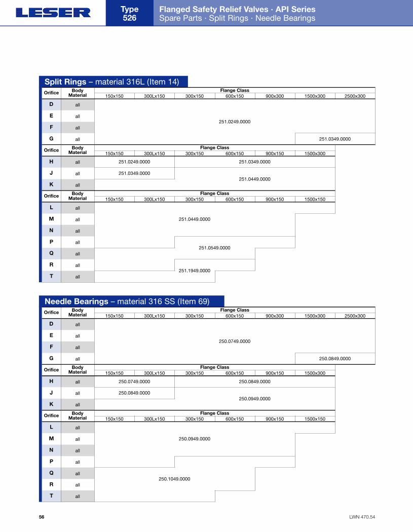
LWN 470.54
Flanged Safety Relief Valves · API Series Spare Parts · Split Rings · Needle Bearings
Type 526
56
Needle Bearings – material 316 SS (Item 69)Orifice Body
Material
D all
all
all
all
250.0749.0000
all
all
all
all
all
all
all
all
all
all
E
F
G
1500x300900x300600x150300x150300Lx150150x150Flange Class
2500x300
Orifice Body Material
H 250.0749.0000
250.0849.0000
250.0849.0000
250.0949.0000
250.0849.0000
J
K
1500x300900x150600x150300x150300Lx150150x150Flange Class
Orifice Body Material
L
250.1049.0000
250.0949.0000M
1500x150900x150600x150300x150300Lx150150x150Flange Class
N
P
Q
R
T
Split Rings – material 316L (Item 14)Orifice Body
Material
D all
all
all
all
251.0249.0000
all
all
all
all
all
all
all
all
all
all
E
F
G
1500x300900x300600x150300x150300Lx150150x150Flange Class
2500x300
Orifice Body Material
H 251.0249.0000
251.0349.0000
251.0349.0000
251.0449.0000
251.0349.0000
J
K
1500x300900x150600x150300x150300Lx150150x150Flange Class
Orifice Body Material
L
251.1949.0000
251.0549.0000
251.0449.0000M
1500x150900x150600x150300x150300Lx150150x150Flange Class
N
P
Q
R
T
Folder API Series 526 NEW 7/13/04 4:41 PM Page 56
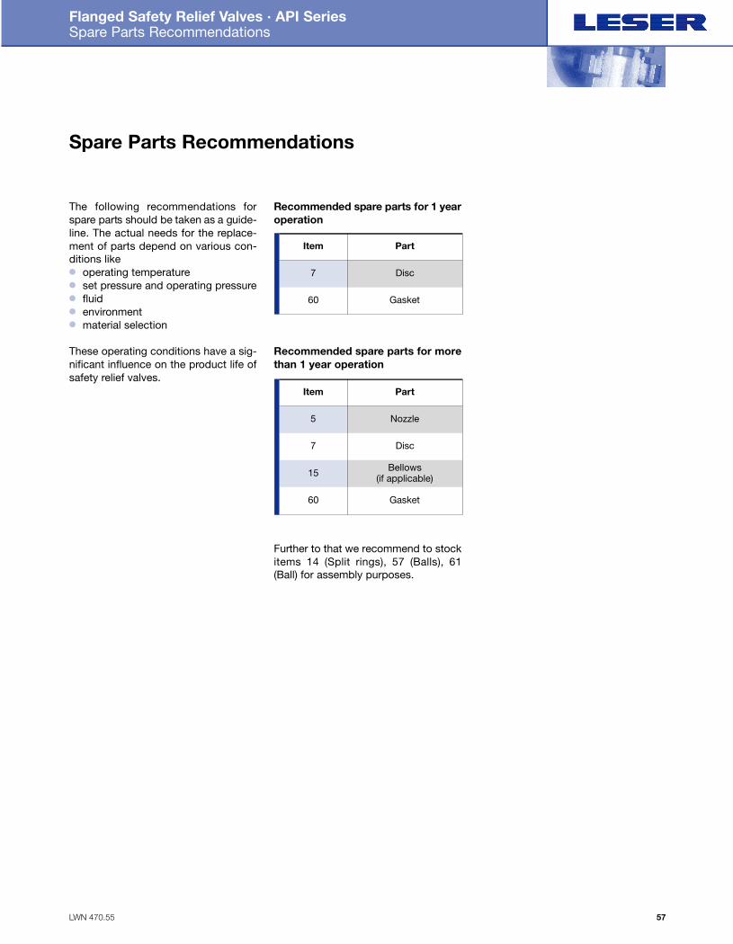
LWN 470.55
Flanged Safety Relief Valves · API Series Spare Parts Recommendations
57
Spare Parts Recommendations
The following recommendations fors p a re parts should be taken as a guide-line. The actual needs for the replace-ment of parts depend on various con-ditions like● operating temperature● set pressure and operating pressure● fluid● environment● material selection
These operating conditions have a sig-nificant influence on the product life ofsafety relief valves.
Recommended spare parts for 1 yearoperation
Recommended spare parts for morethan 1 year operation
Further to that we recommend to stockitems 14 (Split rings), 57 (Balls), 61(Ball) for assembly purposes.
Item Part
Disc7
Gasket60
Item Part
Nozzle5
Disc7
Bellows (if applicable)15
Gasket60
Folder API Series 526 NEW 7/13/04 4:41 PM Page 57
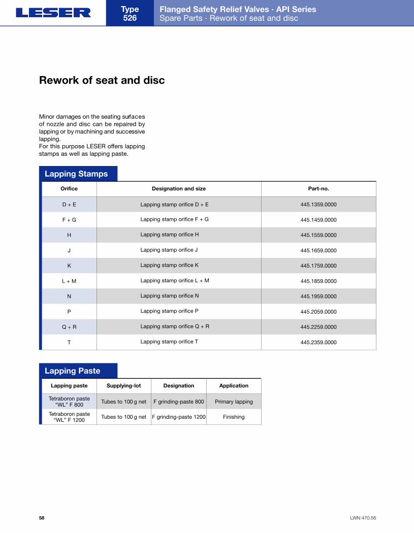
LWN 470.56
Flanged Safety Relief Valves · API Series Spare Parts · Rework of seat and disc
Type 526
58
Minor damages on the seating surf a c e sof nozzle and disc can be repaired bylapping or by machining and successivelapping.For this purpose LESER offers lappingstamps as well as lapping paste.
Rework of seat and disc
Orifice
Lapping stamp orifice D + E 445.1359.0000
445.1459.0000
445.1559.0000
445.1659.0000
445.1759.0000
445.1859.0000
445.1959.0000
445.2059.0000
445.2259.0000
445.2359.0000
D + E
Lapping stamp orifice F + GF + G
Lapping stamp orifice HH
Lapping stamp orifice JJ
Lapping stamp orifice KK
Lapping stamp orifice L + ML + M
Lapping stamp orifice NN
Lapping stamp orifice PP
Lapping stamp orifice Q + RQ + R
Lapping stamp orifice TT
Designation and size Part-no.
Lapping paste Supplying-lot Designation Application
Tubes to 100 g netTetraboron paste “WL” F 800
Tubes to 100 g net
F grinding-paste 800
F grinding-paste 1200
Primary lapping
FinishingTetraboron paste “WL” F 1200
Lapping Paste
Lapping Stamps
Folder API Series 526 NEW 7/13/04 4:41 PM Page 58
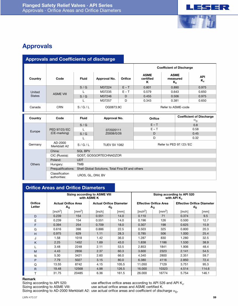
LWN 470.57
Flanged Safety Relief Valves · API Series Approvals · Orifice Areas and Orifice Diameters
59
Approvals and Coefficients of discharge
Country
Country
Code
Code
UnitedStates
Canada
ASME VIII
CRN
Fluid
S / G
S / G / L
L
S / GL
Approval No. Orifice
M37224 E – T
OG0873.9C
M37235 E – TM37246 DM37257 D
0.801
Refer to ASME-code
0.5790.4550.343
0.8900.6430.5060.381
0.975
Europe PED 97/23/EC(CE-marking)
Germany AD-2000Merkblatt A2
S / GL
S / GL
S / G / L
072020111Z0008/0/26
TUEV SV 1082
0.8
Fluid Approval No. Coefficient of DischargeαD
Orifice
0.580.450.32
Refer to PED 97 / 23 / EC
E – TE – T
DD
0.6500.9750.650
ASMEcertified
K
Coefficient of Discharge
ASMEmeasured
KD
APIKd
Others
China: SQL BPVCIC (Russia): GOST, GOSGORTECHNADZORPoland: UDTHungary: TMBPrequalifications: Shell Global Solutions, Total Fina Elf and others
Classificationauthorities: LROS, GL, DNV, BV
Orifice Areas and Orifice Diameters
OrificeLetter
Actual Orifice AreaA0
Sizing according to ASME VIIIwith ASME K
Sizing according to API 520with API Kd
DEFGHJKLMNPQRT
[inch2] [mm2] [inch] [mm] [inch2] [mm2] [inch] [mm]0.239 154 0.551 14.00.2390.3940.6160.9751.582.253.484.435.307.7913.5519.4831.75
15425439862910181452224828563421502787421256820485
0.551 14.00.709 18.00.886 22.51.11 28.31.42 36.01.69 43.02.11 53.52.37 60.32.60 66.03.15 80.04.15 105.54.98 126.56.36 161.5
0.1100.1960.3070.5030.7851.2871.8382.8533.6004.3406.38011.05016.00026.000
71126198325506830
1186184123232800411671291032316774
0.3740.5000.6250.8001.0001.2801.5301.9062.1412.3512.8503.7514.5145.754
9.512.715.920.325.432.538.948.454.559.772.495.3
114.6146.1
Actual Orifice Diameterd0
Effective Orifice AreaA0
Effective Orifice Diameterd0
Approvals
RemarkSizing according to API 520: use effective orifice areas according to API 526 and API Kd.Sizing according to ASME VIII: use actual orifice areas and ASME certified K.Sizing according to AD-2000 Merkblatt A2: use actual orifice areas and coefficient of discharge αD.
Folder API Series 526 NEW 7/13/04 4:42 PM Page 59
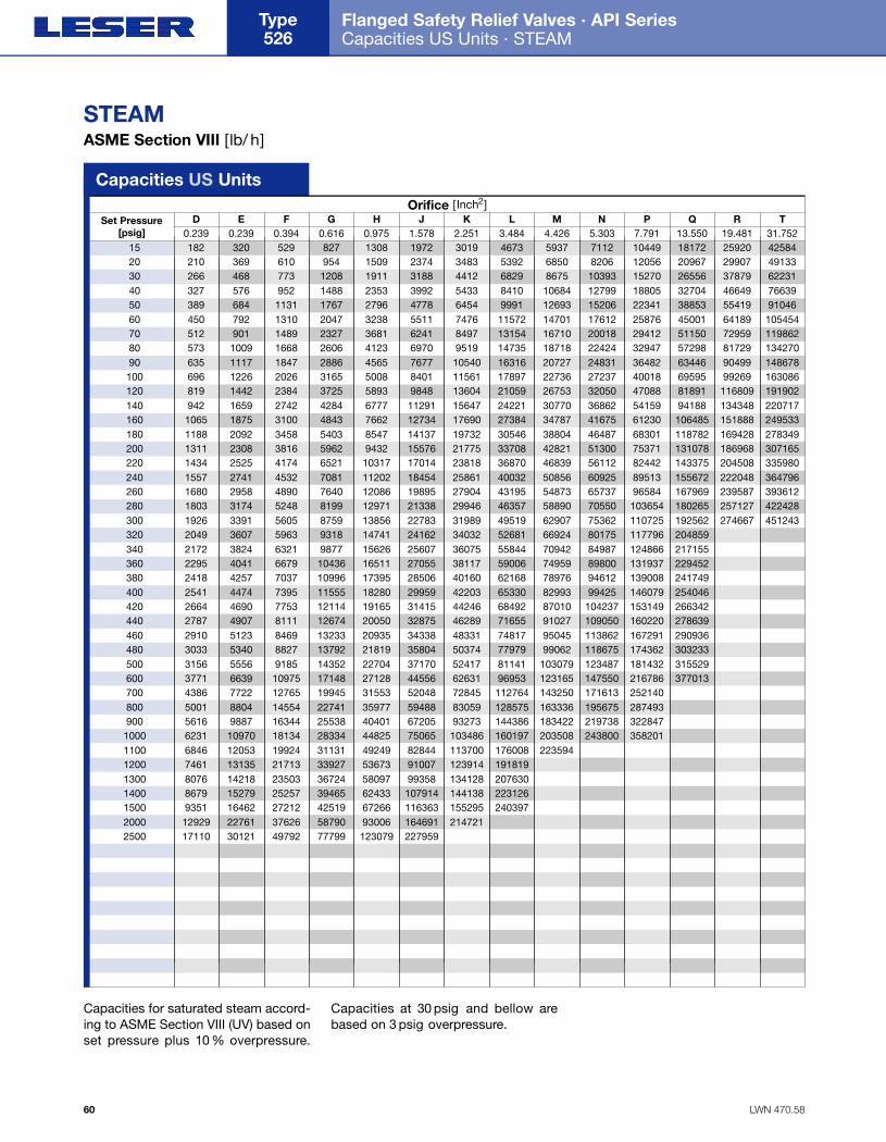
LWN 470.58
Flanged Safety Relief Valves · API Series Capacities US Units · STEAM
Type 526
60
STEAMASME Section VIII [lb/ h]
D E F G H J K L M N P Q R T0.239 0.239 0.394 0.616 0.975 1.578 2.251 3.484 4.426 5.303 7.791 13.550 19.481 31.752
Set Pressure[psig]
Capacities US UnitsOrifice [Inch2]
Capacities for saturated steam accord-ing to ASME Section VIII (UV) based onset pressure plus 10 % overpressure.
Capacities at 30 psig and bellow arebased on 3 psig overpressure.
15 182 320 529 827 1308 1972 3019 4673 5937 7112 10449 18172 25920 4258420 210 369 610 954 1509 2374 3483 5392 6850 8206 12056 20967 29907 4913330 266 468 773 1208 1911 3188 4412 6829 8675 10393 15270 26556 37879 6223140 327 576 952 1488 2353 3992 5433 8410 10684 12799 18805 32704 46649 7663950 389 684 1131 1767 2796 4778 6454 9991 12693 15206 22341 38853 55419 9104660 450 792 1310 2047 3238 5511 7476 11572 14701 17612 25876 45001 64189 10545470 512 901 1489 2327 3681 6241 8497 13154 16710 20018 29412 51150 72959 11986280 573 1009 1668 2606 4123 6970 9519 14735 18718 22424 32947 57298 81729 13427090 635 1117 1847 2886 4565 7677 10540 16316 20727 24831 36482 63446 90499 148678100 696 1226 2026 3165 5008 8401 11561 17897 22736 27237 40018 69595 99269 163086120 819 1442 2384 3725 5893 9848 13604 21059 26753 32050 47088 81891 116809 191902140 942 1659 2742 4284 6777 11291 15647 24221 30770 36862 54159 94188 134348 220717160 1065 1875 3100 4843 7662 12734 17690 27384 34787 41675 61230 106485 151888 249533180 1188 2092 3458 5403 8547 14137 19732 30546 38804 46487 68301 118782 169428 278349200 1311 2308 3816 5962 9432 15576 21775 33708 42821 51300 75371 131078 186968 307165220 1434 2525 4174 6521 10317 17014 23818 36870 46839 56112 82442 143375 204508 335980240 1557 2741 4532 7081 11202 18454 25861 40032 50856 60925 89513 155672 222048 364796260 1680 2958 4890 7640 12086 19895 27904 43195 54873 65737 96584 167969 239587 393612280 1803 3174 5248 8199 12971 21338 29946 46357 58890 70550 103654 180265 257127 422428300 1926 3391 5605 8759 13856 22783 31989 49519 62907 75362 110725 192562 274667 451243320 2049 3607 5963 9318 14741 24162 34032 52681 66924 80175 117796 204859340 2172 3824 6321 9877 15626 25607 36075 55844 70942 84987 124866 217155360 2295 4041 6679 10436 16511 27055 38117 59006 74959 89800 131937 229452380 2418 4257 7037 10996 17395 28506 40160 62168 78976 94612 139008 241749400 2541 4474 7395 11555 18280 29959 42203 65330 82993 99425 146079 254046420 2664 4690 7753 12114 19165 31415 44246 68492 87010 104237 153149 266342440 2787 4907 8111 12674 20050 32875 46289 71655 91027 109050 160220 278639460 2910 5123 8469 13233 20935 34338 48331 74817 95045 113862 167291 290936480 3033 5340 8827 13792 21819 35804 50374 77979 99062 118675 174362 303233500 3156 5556 9185 14352 22704 37170 52417 81141 103079 123487 181432 315529600 3771 6639 10975 17148 27128 44556 62631 96953 123165 147550 216786 377013700 4386 7722 12765 19945 31553 52048 72845 112764 143250 171613 252140800 5001 8804 14554 22741 35977 59488 83059 128575 163336 195675 287493900 5616 9887 16344 25538 40401 67205 93273 144386 183422 219738 3228471000 6231 10970 18134 28334 44825 75065 103486 160197 203508 243800 3582011100 6846 12053 19924 31131 49249 82844 113700 176008 2235941200 7461 13135 21713 33927 53673 91007 123914 1918191300 8076 14218 23503 36724 58097 99358 134128 2076301400 8679 15279 25257 39465 62433 107914 144138 2231261500 9351 16462 27212 42519 67266 116363 155295 2403972000 12929 22761 37626 58790 93006 164691 2147212500 17110 30121 49792 77799 123079 227959
Folder API Series 526 NEW 7/13/04 4:42 PM Page 60
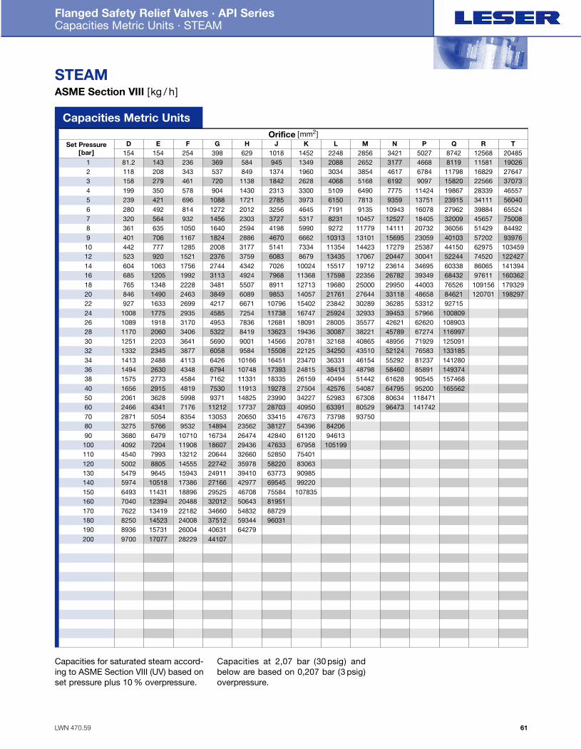
LWN 470.59
Flanged Safety Relief Valves · API Series Capacities Metric Units · STEAM
61
STEAMASME Section VIII [kg / h]
D E F G H J K L M N P Q R T154 154 254 398 629 1018 1452 2248 2856 3421 5027 8742 12568 20485
Set Pressure[bar]
Capacities Metric UnitsOrifice [mm2]
Capacities for saturated steam accord-ing to ASME Section VIII (UV) based onset pressure plus 10 % overpressure.
Capacities at 2,07 bar (30 psig) andbelow are based on 0,207 bar (3 psig)overpressure.
1 81.2 143 236 369 584 945 1349 2088 2652 3177 4668 8119 11581 190262 118 208 343 537 849 1374 1960 3034 3854 4617 6784 11798 16829 276473 158 279 461 720 1138 1842 2628 4068 5168 6192 9097 15820 22566 370734 199 350 578 904 1430 2313 3300 5109 6490 7775 11424 19867 28339 465575 239 421 696 1088 1721 2785 3973 6150 7813 9359 13751 23915 34111 560406 280 492 814 1272 2012 3256 4645 7191 9135 10943 16078 27962 39884 655247 320 564 932 1456 2303 3727 5317 8231 10457 12527 18405 32009 45657 750088 361 635 1050 1640 2594 4198 5990 9272 11779 14111 20732 36056 51429 844929 401 706 1167 1824 2886 4670 6662 10313 13101 15695 23059 40103 57202 9397610 442 777 1285 2008 3177 5141 7334 11354 14423 17279 25387 44150 62975 10345912 523 920 1521 2376 3759 6083 8679 13435 17067 20447 30041 52244 74520 12242714 604 1063 1756 2744 4342 7026 10024 15517 19712 23614 34695 60338 86065 14139416 685 1205 1992 3113 4924 7968 11368 17598 22356 26782 39349 68432 97611 16036218 765 1348 2228 3481 5507 8911 12713 19680 25000 29950 44003 76526 109156 17932920 846 1490 2463 3849 6089 9853 14057 21761 27644 33118 48658 84621 120701 19829722 927 1633 2699 4217 6671 10796 15402 23842 30289 36285 53312 9271524 1008 1775 2935 4585 7254 11738 16747 25924 32933 39453 57966 10080926 1089 1918 3170 4953 7836 12681 18091 28005 35577 42621 62620 10890328 1170 2060 3406 5322 8419 13623 19436 30087 38221 45789 67274 11699730 1251 2203 3641 5690 9001 14566 20781 32168 40865 48956 71929 12509132 1332 2345 3877 6058 9584 15508 22125 34250 43510 52124 76583 13318534 1413 2488 4113 6426 10166 16451 23470 36331 46154 55292 81237 14128036 1494 2630 4348 6794 10748 17393 24815 38413 48798 58460 85891 14937438 1575 2773 4584 7162 11331 18335 26159 40494 51442 61628 90545 15746840 1656 2915 4819 7530 11913 19278 27504 42576 54087 64795 95200 16556250 2061 3628 5998 9371 14825 23990 34227 52983 67308 80634 11847160 2466 4341 7176 11212 17737 28703 40950 63391 80529 96473 14174270 2871 5054 8354 13053 20650 33415 47673 73798 9375080 3275 5766 9532 14894 23562 38127 54396 8420690 3680 6479 10710 16734 26474 42840 61120 94613100 4092 7204 11908 18607 29436 47633 67958 105199110 4540 7993 13212 20644 32660 52850 75401120 5002 8805 14555 22742 35978 58220 83063130 5479 9645 15943 24911 39410 63773 90985140 5974 10518 17386 27166 42977 69545 99220150 6493 11431 18896 29525 46708 75584 107835160 7040 12394 20488 32012 50643 81951170 7622 13419 22182 34660 54832 88729180 8250 14523 24008 37512 59344 96031190 8936 15731 26004 40631 64279200 9700 17077 28229 44107
Folder API Series 526 NEW 7/13/04 4:42 PM Page 61
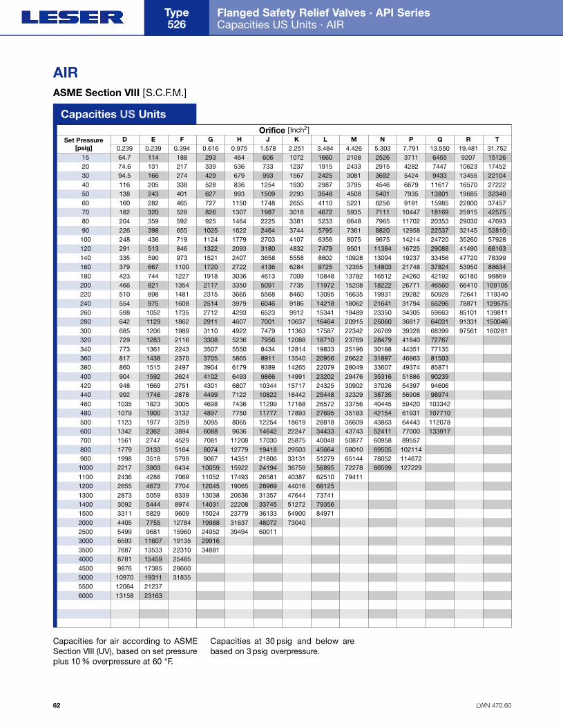
LWN 470.60
Flanged Safety Relief Valves · API Series Capacities US Units · AIR
Type 526
62
AIRASME Section VIII [S.C.F.M.]
Capacities for air according to ASMESection VIII (UV), based on set pre s s u replus 10 % overpressure at 60 °F.
Capacities at 30 psig and below arebased on 3p s ig o v e r p re s s u re .
D E F G H J K L M N P Q R T0.239 0.239 0.394 0.616 0.975 1.578 2.251 3.484 4.426 5.303 7.791 13.550 19.481 31.752
Set Pressure[psig]
Capacities US UnitsOrifice [Inch2]
15 64.7 114 188 293 464 606 1072 1660 2108 2526 3711 6455 9207 1512620 74.6 131 217 339 536 733 1237 1915 2433 2915 4282 7447 10623 1745230 94.5 166 274 429 679 993 1567 2425 3081 3692 5424 9433 13455 2210440 116 205 338 528 836 1254 1930 2987 3795 4546 6679 11617 16570 2722250 138 243 401 627 993 1509 2293 3548 4508 5401 7935 13801 19685 3234060 160 282 465 727 1150 1748 2655 4110 5221 6256 9191 15985 22800 3745770 182 320 528 826 1307 1987 3018 4672 5935 7111 10447 18169 25915 4257580 204 359 592 925 1464 2225 3381 5233 6648 7965 11702 20353 29030 4769390 226 398 655 1025 1622 2464 3744 5795 7361 8820 12958 22537 32145 52810100 248 436 719 1124 1779 2703 4107 6356 8075 9675 14214 24720 35260 57928120 291 513 846 1322 2093 3180 4832 7479 9501 11384 16725 29088 41490 68163140 335 590 973 1521 2407 3658 5558 8602 10928 13094 19237 33456 47720 78399160 379 667 1100 1720 2722 4136 6284 9725 12355 14803 21748 37824 53950 88634180 423 744 1227 1918 3036 4613 7009 10848 13782 16512 24260 42192 60180 98869200 466 821 1354 2117 3350 5091 7735 11972 15208 18222 26771 46560 66410 109105220 510 898 1481 2315 3665 5568 8460 13095 16635 19931 29282 50928 72641 119340240 554 975 1608 2514 3979 6046 9186 14218 18062 21641 31794 55296 78871 129575260 598 1052 1735 2712 4293 6523 9912 15341 19489 23350 34305 59663 85101 139811280 642 1129 1862 2911 4607 7001 10637 16464 20915 25060 36817 64031 91331 150046300 685 1206 1989 3110 4922 7479 11363 17587 22342 26769 39328 68399 97561 160281320 729 1283 2116 3308 5236 7956 12088 18710 23769 28479 41840 72767340 773 1361 2243 3507 5550 8434 12814 19833 25196 30188 44351 77135360 817 1438 2370 3705 5865 8911 13540 20956 26622 31897 46863 81503380 860 1515 2497 3904 6179 9389 14265 22079 28049 33607 49374 85871400 904 1592 2624 4102 6493 9866 14991 23202 29476 35316 51886 90239420 948 1669 2751 4301 6807 10344 15717 24325 30902 37026 54397 94606440 992 1746 2878 4499 7122 10822 16442 25448 32329 38735 56908 98974460 1035 1823 3005 4698 7436 11299 17168 26572 33756 40445 59420 103342480 1079 1900 3132 4897 7750 11777 17893 27695 35183 42154 61931 107710500 1123 1977 3259 5095 8065 12254 18619 28818 36609 43863 64443 112078600 1342 2362 3894 6088 9636 14642 22247 34433 43743 52411 77000 133917700 1561 2747 4529 7081 11208 17030 25875 40048 50877 60958 89557800 1779 3133 5164 8074 12779 19418 29503 45664 58010 69505 102114900 1998 3518 5799 9067 14351 21806 33131 51279 65144 78052 1146721000 2217 3903 6434 10059 15922 24194 36759 56895 72278 86599 1272291100 2436 4288 7069 11052 17493 26581 40387 62510 794111200 2655 4673 7704 12045 19065 28969 44016 681251300 2873 5059 8339 13038 20636 31357 47644 737411400 3092 5444 8974 14031 22208 33745 51272 793561500 3311 5829 9609 15024 23779 36133 54900 849712000 4405 7755 12784 19988 31637 48072 730402500 5499 9681 15960 24952 39494 600113000 6593 11607 19135 299163500 7687 13533 22310 348814000 8781 15459 254854500 9876 17385 286605000 10970 19311 318355500 12064 212376000 13158 23163
Folder API Series 526 NEW 7/13/04 4:42 PM Page 62
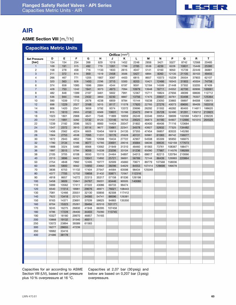
LWN 470.61
Flanged Safety Relief Valves · API Series Capacities Metric Units · AIR
63
AIRASME Section VIII [mn
3/ h]
Capacities for air according to ASMESection VIII (UV), based on set pre s s u replus 10 % overpressure at 16 °C.
Capacities at 2,07 bar (30 psig) andbelow are based on 0,207 bar (3 psig)overpressure.
D E F G H J K L M N P Q R T154 154 254 398 629 1018 1452 2248 2856 3421 5027 8742 12568 20485
Set Pressure[bar]
Capacities Metric UnitsOrifice [mm2]
1 109 191 315 492 779 1261 1799 2785 3538 4239 6228 10831 15449 253802 158 278 458 716 1133 1833 2615 4047 5141 6160 9050 15739 22449 368813 211 372 614 959 1519 2458 3506 5427 6894 8260 12135 21105 30103 494554 266 467 771 1205 1907 3087 4403 6815 8657 10373 15239 26504 37803 621075 320 563 928 1450 2296 3715 5300 8203 10421 12486 18343 31903 45504 747586 374 658 1085 1696 2684 4344 6197 9591 12184 14599 21448 37302 53205 874097 428 753 1242 1941 3073 4973 7094 10979 13948 16711 24552 42700 60906 1000618 482 848 1399 2187 3461 5602 7991 12367 15711 18824 27656 48099 68606 1127129 536 944 1556 2432 3850 6230 8887 13756 17475 20937 30761 53498 76307 12536410 590 1039 1713 2678 4238 6859 9784 15144 19238 23050 33865 58897 84008 13801512 698 1229 2027 3168 5015 8117 11578 17920 22765 27276 40073 69695 99409 16331814 806 1420 2341 3659 5792 9374 13372 20696 26292 31502 46282 80493 114811 18862016 915 1610 2655 4150 6569 10631 15166 23473 29819 35728 52490 91291 130212 21392318 1023 1801 2968 4641 7346 11889 16959 26249 33346 39954 58699 102088 145613 23922620 1131 1991 3282 5132 8123 13146 18753 29025 36873 44180 64907 112886 161015 26452922 1239 2182 3596 5623 8900 14404 20547 31802 40400 48406 71116 12368424 1347 2372 3910 6114 9677 15661 22341 34578 43927 52632 77325 13448226 1456 2562 4224 6605 10454 16919 24135 37355 47454 56857 83533 14528028 1564 2753 4538 7095 11231 18176 25928 40131 50981 61083 89742 15607730 1672 2943 4852 7586 12008 19434 27722 42907 54508 65309 95950 16687532 1780 3134 5166 8077 12785 20691 29516 45684 58036 69535 102159 17767334 1888 3324 5480 8568 13562 21949 31310 48460 61563 73761 108367 18847136 1997 3515 5794 9059 14339 23206 33104 51236 65090 77987 114576 19926938 2105 3705 6108 9550 15115 24464 34897 54013 68617 82213 120784 21006640 2213 3896 6422 10041 15892 25721 36691 56789 72144 86439 126993 22086450 2754 4848 7992 12495 19777 32009 45660 70671 89779 107568 15803660 3295 5800 9562 14950 23662 38296 54629 84553 107414 128698 18907870 3836 6753 11132 17404 27547 44584 63598 98434 12504980 4377 7705 12702 19858 31432 50871 72567 11231690 4918 8657 14272 22313 35317 57158 81536 126198100 5458 9609 15841 24767 39201 63446 90505 140080110 5999 10562 17411 27222 43086 69733 99474120 6540 11514 18981 29676 46971 76021 108443130 7081 12466 20551 32130 50856 82308 117412140 7622 13418 22121 34585 54741 88596 126381150 8163 14371 23691 37039 58625 94883 135350160 8704 15323 25261 39494 62510 101171170 9245 16275 26830 41948 66395 107458180 9786 17228 28400 44403 70280 113745190 10327 18180 29970 46857 74165200 10868 19132 31540 49311250 13572 23894 39389 61583300 16277 28655 47239350 18982 33416400 21686 38178
Folder API Series 526 NEW 7/13/04 4:42 PM Page 63
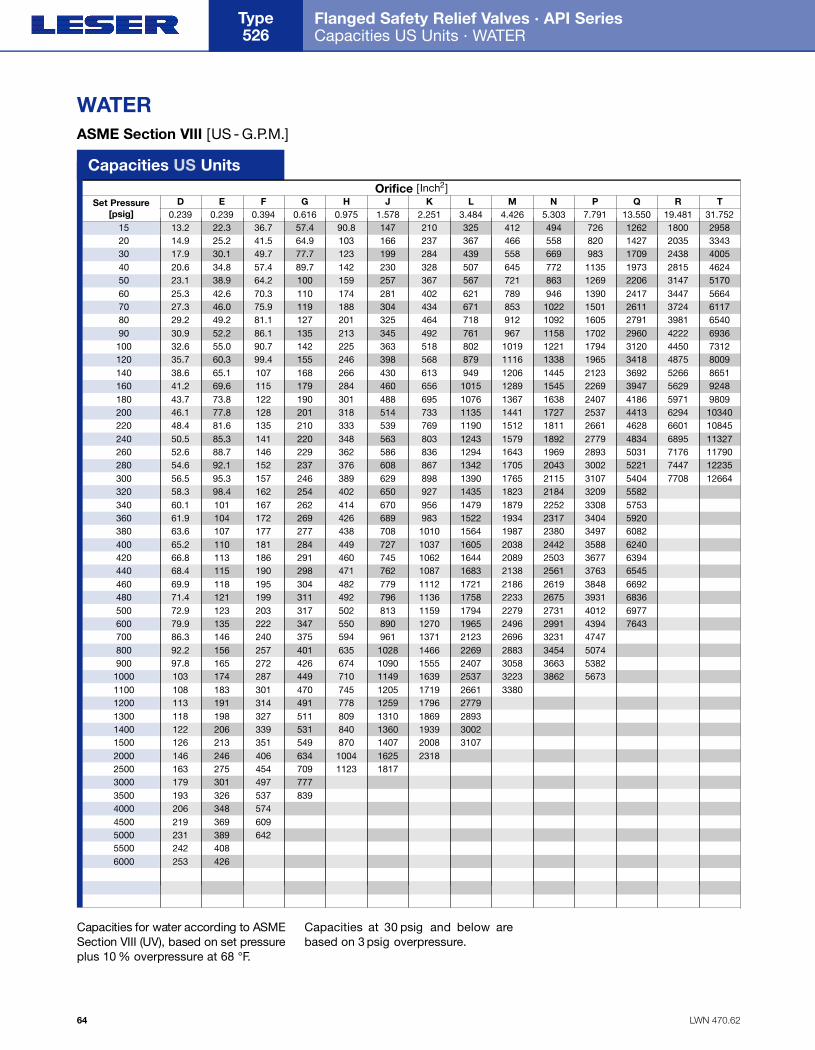
LWN 470.62
Flanged Safety Relief Valves · API Series Capacities US Units · WATER
Type 526
64
WATERASME Section VIII [US - G.P.M.]
Capacities for water according to ASMESection VIII (UV), based on set pre s s u replus 10 % overpressure at 68 °F.
Capacities at 30 psig and below arebased on 3 psig overpressure.
D E F G H J K L M N P Q R T0.239 0.239 0.394 0.616 0.975 1.578 2.251 3.484 4.426 5.303 7.791 13.550 19.481 31.752
Set Pressure[psig]
Capacities US UnitsOrifice [Inch2]
15 13.2 22.3 36.7 57.4 90.8 147 210 325 412 494 726 1262 1800 295820 14.9 25.2 41.5 64.9 103 166 237 367 466 558 820 1427 2035 334330 17.9 30.1 49.7 77.7 123 199 284 439 558 669 983 1709 2438 400540 20.6 34.8 57.4 89.7 142 230 328 507 645 772 1135 1973 2815 462450 23.1 38.9 64.2 100 159 257 367 567 721 863 1269 2206 3147 517060 25.3 42.6 70.3 110 174 281 402 621 789 946 1390 2417 3447 566470 27.3 46.0 75.9 119 188 304 434 671 853 1022 1501 2611 3724 611780 29.2 49.2 81.1 127 201 325 464 718 912 1092 1605 2791 3981 654090 30.9 52.2 86.1 135 213 345 492 761 967 1158 1702 2960 4222 6936100 32.6 55.0 90.7 142 225 363 518 802 1019 1221 1794 3120 4450 7312120 35.7 60.3 99.4 155 246 398 568 879 1116 1338 1965 3418 4875 8009140 38.6 65.1 107 168 266 430 613 949 1206 1445 2123 3692 5266 8651160 41.2 69.6 115 179 284 460 656 1015 1289 1545 2269 3947 5629 9248180 43.7 73.8 122 190 301 488 695 1076 1367 1638 2407 4186 5971 9809200 46.1 77.8 128 201 318 514 733 1135 1441 1727 2537 4413 6294 10340220 48.4 81.6 135 210 333 539 769 1190 1512 1811 2661 4628 6601 10845240 50.5 85.3 141 220 348 563 803 1243 1579 1892 2779 4834 6895 11327260 52.6 88.7 146 229 362 586 836 1294 1643 1969 2893 5031 7176 11790280 54.6 92.1 152 237 376 608 867 1342 1705 2043 3002 5221 7447 12235300 56.5 95.3 157 246 389 629 898 1390 1765 2115 3107 5404 7708 12664320 58.3 98.4 162 254 402 650 927 1435 1823 2184 3209 5582340 60.1 101 167 262 414 670 956 1479 1879 2252 3308 5753360 61.9 104 172 269 426 689 983 1522 1934 2317 3404 5920380 63.6 107 177 277 438 708 1010 1564 1987 2380 3497 6082400 65.2 110 181 284 449 727 1037 1605 2038 2442 3588 6240420 66.8 113 186 291 460 745 1062 1644 2089 2503 3677 6394440 68.4 115 190 298 471 762 1087 1683 2138 2561 3763 6545460 69.9 118 195 304 482 779 1112 1721 2186 2619 3848 6692480 71.4 121 199 311 492 796 1136 1758 2233 2675 3931 6836500 72.9 123 203 317 502 813 1159 1794 2279 2731 4012 6977600 79.9 135 222 347 550 890 1270 1965 2496 2991 4394 7643700 86.3 146 240 375 594 961 1371 2123 2696 3231 4747800 92.2 156 257 401 635 1028 1466 2269 2883 3454 5074900 97.8 165 272 426 674 1090 1555 2407 3058 3663 53821000 103 174 287 449 710 1149 1639 2537 3223 3862 56731100 108 183 301 470 745 1205 1719 2661 33801200 113 191 314 491 778 1259 1796 27791300 118 198 327 511 809 1310 1869 28931400 122 206 339 531 840 1360 1939 30021500 126 213 351 549 870 1407 2008 31072000 146 246 406 634 1004 1625 23182500 163 275 454 709 1123 18173000 179 301 497 7773500 193 326 537 8394000 206 348 5744500 219 369 6095000 231 389 6425500 242 4086000 253 426
Folder API Series 526 NEW 7/13/04 4:43 PM Page 64

LWN 470.63
Flanged Safety Relief Valves · API Series Capacities Metric Units · WATER
65
WATERASME Section VIII [103 kg/ h]
Capacities for water according to ASMESection VIII (UV), based on set pre s s u replus 10 % overpressure at 20 °C.
Capacities at 2,07 bar (30 psig) andbelow are based on 0,207 bar (3 psig)overpressure.
D E F G H J K L M N P Q R T154 154 254 398 629 1018 1452 2248 2856 3421 5027 8742 12568 20485
Set Pressure[bar]
Capacities Metric UnitsOrifice [mm2]
1 2.95 4.99 8.22 12.9 20.3 32.9 47.0 72.7 92.4 111 163 283 403 6632 4.00 6.75 11.1 17.4 27.5 44.5 63.5 98.3 125 150 220 382 545 8963 4.89 8.25 13.6 21.3 33.6 54.5 77.7 120 153 183 269 468 667 10964 5.64 9.52 15.7 24.5 38.9 62.9 89.7 139 176 211 310 540 770 12655 6.31 10.6 17.6 27.4 43.4 70.3 100 155 197 236 347 604 861 14156 6.91 11.7 19.2 30.1 47.6 77.0 110 170 216 259 380 661 943 15507 7.46 12.6 20.8 32.5 51.4 83.2 119 184 233 280 411 714 1019 16748 7.98 13.5 22.2 34.7 54.9 88.9 127 196 249 299 439 764 1089 17899 8.46 14.3 23.6 36.8 58.3 94.3 135 208 265 317 466 810 1155 189810 8.92 15.1 24.8 38.8 61.4 99.4 142 220 279 334 491 854 1218 200112 9.77 16.5 27.2 42.5 67.3 109 155 240 305 366 538 935 1334 219214 10.6 17.8 29.4 45.9 72.7 118 168 260 330 395 581 1010 1441 236716 11.3 19.0 31.4 49.1 77.7 126 179 278 353 423 621 1080 1540 253118 12.0 20.2 33.3 52.1 82.4 133 190 295 374 448 659 1145 1634 268420 12.6 21.3 35.1 54.9 86.9 141 201 310 394 473 694 1207 1722 282922 13.2 22.3 36.8 57.6 91.1 147 210 326 414 496 728 126624 13.8 23.3 38.5 60.1 95.2 154 220 340 432 518 761 132326 14.4 24.3 40.0 62.6 99.1 160 229 354 450 539 792 137728 14.9 25.2 41.5 64.9 103 166 237 367 467 559 821 142930 15.5 26.1 43.0 67.2 106 172 246 380 483 579 850 147932 16.0 26.9 44.4 69.4 110 178 254 393 499 598 878 152734 16.4 27.8 45.8 71.6 113 183 262 405 514 616 905 157436 16.9 28.6 47.1 73.6 117 189 269 417 529 634 931 162038 17.4 29.4 48.4 75.7 120 194 276 428 544 651 957 166440 17.8 30.1 49.7 77.6 123 199 284 439 558 668 982 170850 19.9 33.7 55.5 86.8 137 222 317 491 624 747 109860 21.9 36.9 60.8 95.1 150 244 347 538 683 818 120270 23.6 39.8 65.7 103 163 263 375 581 73880 25.2 42.6 70.2 110 174 281 401 62190 26.8 45.2 74.5 116 184 298 426 659100 28.2 47.6 78.5 123 194 314 449 694110 29.6 49.9 82.3 129 204 330 470120 30.9 52.2 86.0 134 213 344 491130 32.2 54.3 89.5 140 222 358 511140 33.4 56.3 92.9 145 230 372 531150 34.6 58.3 96.1 150 238 385 549160 35.7 60.2 99.3 155 246 398170 36.8 62.1 102 160 253 410180 37.8 63.9 105 165 261 422190 38.9 65.6 108 169 268200 39.9 67.3 111 174250 44.6 75.3 124 194300 48.9 82.5 136350 52.8 89.1400 56.4 95.2
Folder API Series 526 NEW 7/13/04 4:43 PM Page 65
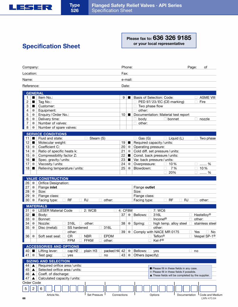
LWN 470.64
Flanged Safety Relief Valves · API Series Specification Sheet
Type 526
66
Specification SheetPlease fax to: 636 326 9185
or your local representative
Company: Phone: Page: of
Location: Fax:
Name: e-mail:
Reference: Date:
G E N E R A L1 ■ Item No.: 9 ■ Basis of Selection: Code: ■ ASME VIII2 ■ Tag No.: ■ PED 97/ 23/ EC (CE-marking) ■ Fire3 ■ Customer: ■ Two phase flow4 ● Equipment: ■ other:5 ● Enquiry / Order No.: 10 ■ Documentation: Material test report6 ● Delivery time: ■ body ■ bonnet ■ nozzle7 ● Number of valves: ■ other:8 ● Number of spare valves:
SIZING AND SELECTION44 ▲ Required orifice area / units:45 ▲ Selected orifice area / units:46 ▲ Coeff. of discharge:47 ▲ Calculated capacity / units:
ACCESSORIES AND OPTIONS40 ■ Lifting lever: ■ cap H2 ■ plain H3 ■ packed H4 42 ● Bellows: ■ yes ■ no41 ● Test gag: ■ yes ■ no 43 ● Others (specify):
M AT E R I A L S31 ● LESER Material Code ■ 2: WCB ■ 4: CF8M ■ 7: WC632 ■ Body: 37 ● Bellows: ■ 316L ■ Hastelloy®
33 ● Bonnet: ■ Inconel® ■ other:34 ● Nozzle: ■ 316L ■ other: 38 ● Spring: ■ high temp. alloy steel ■ stainless steel35 ● Disc (metal): ■ SS hardened ■ 316L ■ other:
■ other: 39 ● Comply with NACE MR 0175 ■ Yes ■ No36 ● Soft seat seal: ■ CR ■ NBR ■ EPDM ■ Teflon® ■ Vespel SP-1®
■ FPM ■ FFKM ■ other: ■ Kel-F®
VA LVE CONSTRUCTION26 ● Orifice Designation:27 ● Flange inlet Flange outlet28 ● Size: Size:29 ● Flange class: Flange class:30 ● Facing type: ■ RF ■ RJ ■ other: Facing type: ■ RF ■ RJ ■ other:
S E RVICE CONDITIONS11 ■ Fluid and state: ■ Steam (S) ■ Gas (G) ■ Liquid (L) ■ Two phase12 ■ Molecular weight: 19 ■ Required capacity / units:13 ● Coefficient C: 20 ● Operating pressure: 14 ● Ratio of specific heats k: 21 ● Cold diff. set pressure / units:15 ● Compressibility factor Z: 22 ■ Const. back pressure / units:16 ■ Spec. gravity / units: 23 ■ Var. back pressure / units:17 ● Viscosity / units: 24 ● Overpressure: ■ 10 % ■ …… %18 ■ Relieving temperature / units: 25 ● Blowdown: ■ 7 % ■ 10 %
■ 20% ■ …… %
■ Please fill in these fields in any case.● Please fill in these fields if possible.▲ These fields will be completed by the supplier.
5 2 6 .Order Code
Article No. Set Pressure Connections Options Documentation Code and Medium
Folder API Series 526 NEW 7/13/04 4:43 PM Page 66
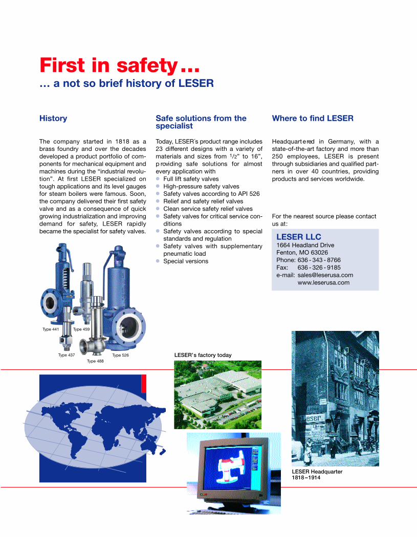
First in safety…… a not so brief history of LESER
Type 526Type 488
Type 437
Type 441 Type 459
LESER’s factory today
LESER Headquarter1818 –1914
History
The company started in 1818 as abrass foundry and over the decadesdeveloped a product portfolio of com-ponents for mechanical equipment andmachines during the “industrial revolu-tion”. At first LESER specialized ontough applications and its level gaugesfor steam boilers were famous. Soon,the company delivered their first safetyvalve and as a consequence of quickgrowing industrialization and improvingdemand for safety, LESER rapidlybecame the specialist for safety valves.
Safe solutions from thespecialist
Today, LESER´s product range includes23 different designs with a variety ofmaterials and sizes from 1/2” to 16”,p roviding safe solutions for almostevery application with● Full lift safety valves● High-pressure safety valves● Safety valves according to API 526● Relief and safety relief valves● Clean service safety relief valves● Safety valves for critical service con-
ditions● Safety valves according to special
standards and regulation● Safety valves with supplementary
pneumatic load● Special versions
Where to find LESER
H e a d q u a rt e red in Germ a n y, with astate-of-the-art factory and more than250 employees, LESER is pre s e n tthrough subsidiaries and qualified part-ners in over 40 countries, providingproducts and services worldwide.
For the nearest source please contactus at:
LESER LLC1664 Headland DriveFenton, MO 63026Phone: 636 - 343 - 8766Fax: 636 - 326 - 9185e-mail: [email protected]
www.leserusa.com
Folder API Series 526 NEW 7/13/04 4:43 PM Page 67
LESER LLC 1664 Headland DriveFenton, MO 63026
Phone: 636 - 343 - 8766Fax: 636 - 326 - 9185
e-mail: [email protected]
The Safety Va l v e
API Series CatalogEdition June 2004
LWN 470.01-470.64 / 06.2004 / 2000
Folder API Series 526 NEW 7/13/04 4:43 PM Page 68


