Air Terminal Devices
Horizontal and Vertical
Sizes 02-12
Force-Flo™ Cabinet Heater
CAB-PRC001-ENMarch 2003
© 2003 American Standard Inc. CAB-PRC001-EN
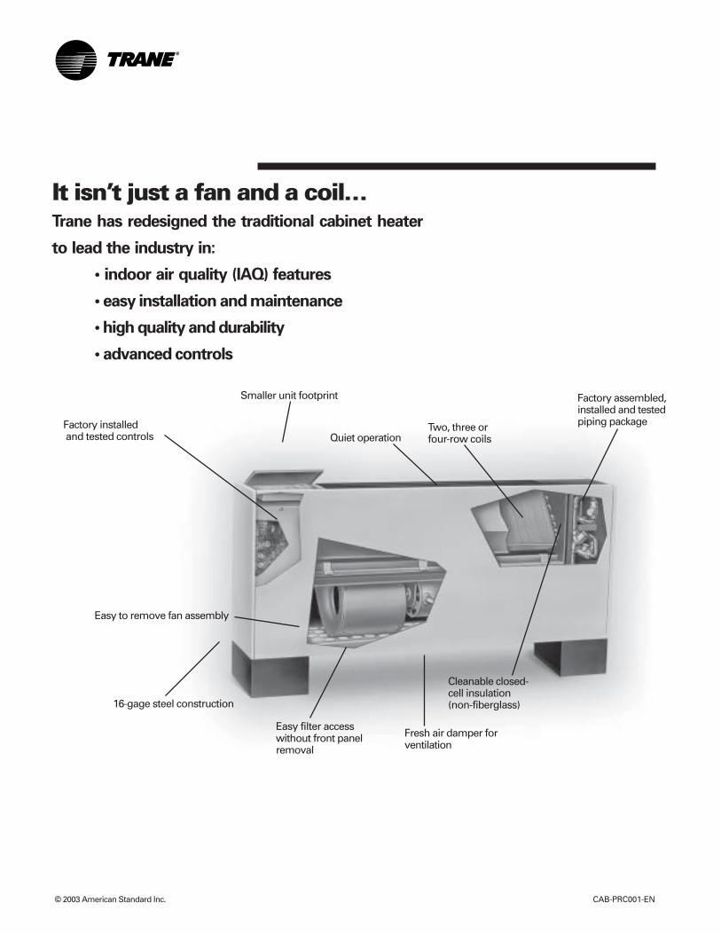
It isn’t just a fan and a coil…Trane has redesigned the traditional cabinet heater
to lead the industry in:
• indoor air quality (IAQ) features
• easy installation and maintenance
• high quality and durability
• advanced controls
Cleanable closed-cell insulation(non-fiberglass)
Two, three orfour-row coils
Easy filter accesswithout front panelremoval
Smaller unit footprint
Easy to remove fan assembly
Quiet operation
16-gage steel construction
Factory assembled,installed and testedpiping packageFactory installed
and tested controls
Fresh air damper forventilation
CAB-PRC001-EN 3
Contents
Introduction 2
Features and Benefits 4
Selection Procedure 5Model Number Description 5General Data 7
Performance Data 18Hot Water Coils 19Steam Coils 22Controls 24
Electrical Data 30
Dimensions and Weights 34
Mechanical Specifications 49Options 51
Features andBenefits
CAB-PRC001-EN4
The Force-Flo™ cabinet heater meets thestandards of today’s market, as well asthe anticipated needs of tomorrow’smarket. The tradition that companyfounder Reuben Trane began in 1913continues with the latest generation ofcabinet heaters from Trane.
The Force-Flo cabinet heater is the leaderin these key areas:• Indoor Air Quality (IAQ)• Controls• Flexibility• Quality• Serviceability
Today’s HVAC market is concerned withissues such as indoor air quality (IAQ)and CFCs that demand a change in HVACproducts. In addition, renovation hasovertaken new construction in thecabinet heater market — demanding adesign that caters to renovation issues.Trane is concerned with these issues,too. That’s why we designed the Force-Flo cabinet heater as an integral part ofthe company’s system solutions withstandard IAQ-related features thatcomply with ASHRAE 62.
IAQ Design• Closed-cell insulation is standard on all
units to help prevent fiberglass in theairstream.
• Easy filter access encourages frequentchanging.
• Force-Flo cabinet heaters have a blow-thru design.
Controls• All controls are factory-mounted and
tested to minimize field setup.• Controls are wired with a 24 VAC
transformer to keep only a singlesource power connection requirementto the unit.
• All wall-mounted zone sensors requireonly low voltage control wiring fromthe device to the unit control box. (Noline voltage.)
• The Tracer® controls family introducesthe latest in control technology with theTracer ZN010, ZN510, and ZN520controllers.
• The random startup feature helpsreduce electrical demand peaks byrandomly staggering multiple units atstartup.
• Occupied/unoccupied operation allowsthe controller to utilize unoccupiedtemperature setpoints for energysavings.
• Warm-up energy feature is standardwith Trane controls.
• Continuous fan or fan cycling is avail-able with Tracer ZN010 or ZN510.
• Monitor unit operation using Tracer®
Summit building management systemwith Tracer ZN510 or ZN520.
• To customize unit control, TracerSummit or Rover™ software will allowfield modification of Tracer ZN510 andZN520 default settings. Rover will allowfield-modification of Tracer ZN010default settings.
• Maximize cabinet heater systemefficiency with modulating valves onunits with Tracer ZN520.
Flexibility• Two, three, and four-row hot water coils
allow greater design flexibility. Steamdistributing or electric heat coils arealso available.
• Fan motors are available for either highstatic (0.4-inch external static pressure)or free discharge applications.
• Piping is factory assembled, mountedand tested. Units are also availablewithout piping.
• Factory piping options include intercon-necting piping, control valves, and endvalves. Deluxe piping also has unionsand a strainer.
• Control options range from a simple fanspeed switch to a DDC controller thatcan tie into a Tracer Summit® buildingautomation system.
• The extended end pocket option adds 8-inches (20 cm) to the piping end ofcabinet style units.
• Slope-top vertical cabinet units are anexcellent application for school anddormitories to prevent items frombeing placed on top of the units.
• Vertical wall hung units are used investibules, bathrooms, stairwells, orother applications when the unit cannotbe installed on the floor
• Inverted unit models allow heating tocirculate from the bottom of the unit.
Quality• Coils and piping packages are air and
leak-tested before mounting on theunit.
• Coil piping connections are also air andleak-tested after mounting on the unit.
• All control end devices and movingcomponents (fans and motors) arecomputer-tested after units arecomplete.
Serviceability• Filters are easily removable and
changed without removing the frontpanel on vertical cabinet units.
• Motors are easy to disconnect from thefan board, allowing easy service.
• The manual output test function is aninvaluable troubleshooting tool. Bysimply pressing the test button on theTracer ZN510, ZN520, or ZN010;service personnel can manuallyexercise outputs in a pre-definedsequence.
SelectionProcedure
CAB-PRC001-EN 5
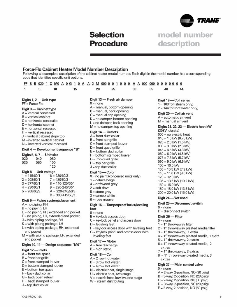
Digit 19 — Coil series1 = 108 fpf (steam only)2 = 144 fpf (hot water only)
Digit 20 — Coil air ventA = automatic air ventM = manual air vent
Digits 21, 22, 23 — Electric heat kW(208V derate)000 = no electric heat010 = 1.0 kW (0.75 kW)020 = 2.0 kW (1.5 kW)030 = 3.0 kW (2.3 kW)045 = 4.5 kW (3.3 kW)060 = 6.0 kW (4.5 kW)075 = 7.5 kW (5.7 kW)090 = 9.0 kW (6.6 kW)100 = 10.0 kW105 = 10.5 kW (7.9 kW)110 = 11.0 kW (9.0 kW)120 = 12.0 kW135 = 13.5 kW (10.2 kW)150 = 15.0 kW180 = 18.0 kW (13.5 kW)200 = 20.0 kW (15.0 kW)
Digit 24 —Not used
Digit 25 — Disconnect switch0 = noneD = disconnect switch
Digit 26 — Filter0 = none1 = 1” throwaway filter2 = 1” throwaway pleated media filter3 = 1” throwaway, 1 extra4 = 1” throwaway pleated media, 1 extra5 = 1” throwaway, 2 extras6 = 1” throwaway pleated media, 2
extras7 = 1” throwaway, 3 extras8 = 1” throwaway pleated media, 3
extras
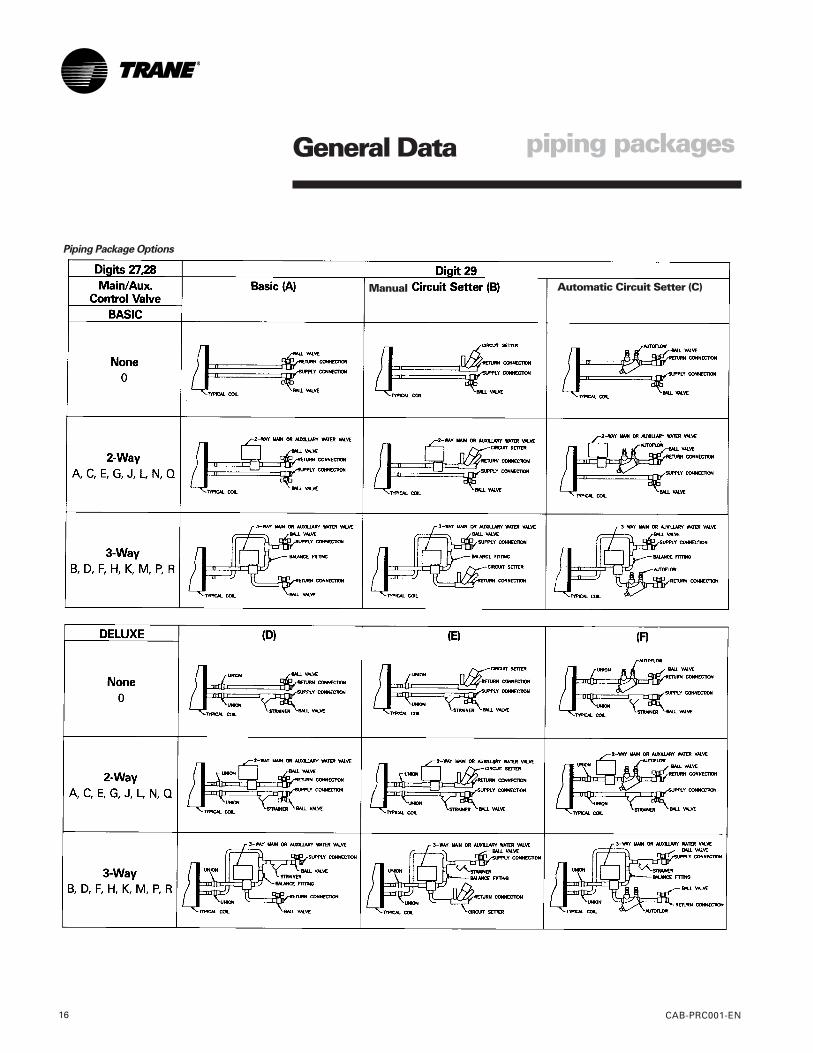
Digit 27 — Main control valve0 = noneA = 2-way, 2-position, NO (30 psig)B = 3-way, 2-position, NO (28 psig)C = 2-way, 2-position, NC (30 psig)D = 3-way, 2-position, NC (20 psig)E = 2-way, 2-position, NO (50 psig)
Digits 1, 2 — Unit typeFF = Force-Flo
Digit 3 — Cabinet typeA = vertical concealedB = vertical cabinetC = horizontal concealedD = horizontal cabinetE = horizontal recessedH = vertical recessedJ = vertical cabinet slope topM =inverted vertical cabinetN = inverted vertical recessed
Digit 4 — Development sequence “B”
Digits 5, 6, 7 — Unit size020 040 080030 060 100
120
Digit 8 — Unit voltage1 = 115/60/1 6 = 230/60/32 = 208/60/1 7 = 480/60/33 = 277/60/1 8 = 110-120/50/14 = 230/60/1 9 = 220-240/50/15 = 208/60/3 A = 220-240/50/3
B = 380-415/50/3
Digit 9 — Piping system/placementA = no piping, RHB = no piping, LHE = no piping, RH, extended end pocketF = no piping, LH, extended end pocketJ = with piping package, RHK = with piping package, LHL = with piping package, RH, extended
end pocketM = with piping package, LH, extended
end pocket
Digits 10, 11 — Design sequence “M0”
Digit 12 — InletsA = front toe spaceB = front bar grilleC = front stamped louverD = bottom stamped louverE = bottom toe spaceF = back duct collarG = back open returnH = back stamped louverJ = top duct collar
FF B B 020 1 C M0 A 0 G 1 0 A A 2 M 000 0 0 1 0 0 0 A A 000 000 0 0 0 0 0 0 0
1 5 10 15 20 25 30 35 40 44
Digit 13 — Fresh air damper0 = noneA = manual, bottom openingB = manual, back openingC = manual, top openingK = no damper, bottom openingL = no damper, back openingM = no damper, top opening
Digit 14 — OutletsA = front duct collarB = front bar grilleC = front stamped louverD = front quad grilleE = bottom duct collarF = bottom stamped louverG = top quad grilleH = top bar grilleJ = top duct collar
Digit 15 — Color0 = no paint (concealed units only)1 = deluxe beige4 = driftwood grey2 = soft dove5 = stone grey3 = cameo white6 = rose mauve
Digit 16 — Tamperproof locks/levelingfeet0 = noneB = keylock access doorC = keylock panel and access doorD = leveling feetF = keylock access door with leveling feetG = keylock panel and access door with
leveling feet
Digit 17 — MotorA = free dischargeB = high static
Digit 18 — CoilA = 2 row hot waterB = 3 row hot waterC = 4 row hot waterN = electric heat, single stageU = electric heat, two stageV = electric heat, low kw, one stageW = steam distributing
Force-Flo Cabinet Heater Model Number DescriptionFollowing is a complete description of the cabinet heater model number. Each digit in the model number has a correspondingcode that identifies specific unit options.
model numberdescription
SelectionProcedure
CAB-PRC001-EN6
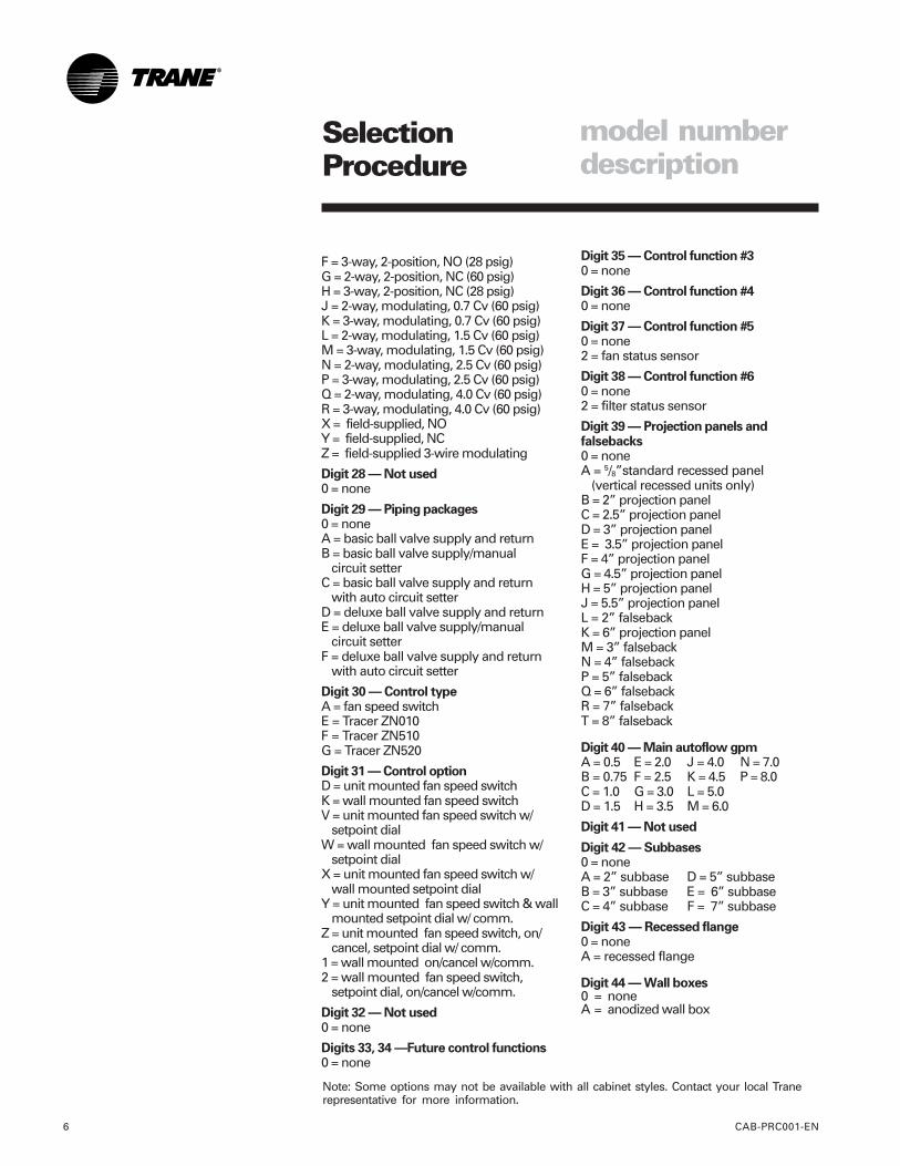
Note: Some options may not be available with all cabinet styles. Contact your local Tranerepresentative for more information.
model numberdescription
F = 3-way, 2-position, NO (28 psig)G = 2-way, 2-position, NC (60 psig)H = 3-way, 2-position, NC (28 psig)J = 2-way, modulating, 0.7 Cv (60 psig)K = 3-way, modulating, 0.7 Cv (60 psig)L = 2-way, modulating, 1.5 Cv (60 psig)M = 3-way, modulating, 1.5 Cv (60 psig)N = 2-way, modulating, 2.5 Cv (60 psig)P = 3-way, modulating, 2.5 Cv (60 psig)Q = 2-way, modulating, 4.0 Cv (60 psig)R = 3-way, modulating, 4.0 Cv (60 psig)X = field-supplied, NOY = field-supplied, NCZ = field-supplied 3-wire modulating
Digit 28 — Not used0 = none
Digit 29 — Piping packages0 = noneA = basic ball valve supply and returnB = basic ball valve supply/manual
circuit setterC = basic ball valve supply and return
with auto circuit setterD = deluxe ball valve supply and returnE = deluxe ball valve supply/manual
circuit setterF = deluxe ball valve supply and return
with auto circuit setter
Digit 30 — Control typeA = fan speed switchE = Tracer ZN010F = Tracer ZN510G = Tracer ZN520
Digit 31 — Control optionD = unit mounted fan speed switchK = wall mounted fan speed switchV = unit mounted fan speed switch w/
setpoint dialW = wall mounted fan speed switch w/
setpoint dialX = unit mounted fan speed switch w/
wall mounted setpoint dialY = unit mounted fan speed switch & wall
mounted setpoint dial w/ comm.Z = unit mounted fan speed switch, on/
cancel, setpoint dial w/ comm.1 = wall mounted on/cancel w/comm.2 = wall mounted fan speed switch,
setpoint dial, on/cancel w/comm.
Digit 32 — Not used0 = none
Digits 33, 34 —Future control functions0 = none
Digit 35 — Control function #30 = none
Digit 36 — Control function #40 = none
Digit 37 — Control function #50 = none2 = fan status sensor
Digit 38 — Control function #60 = none2 = filter status sensor
Digit 39 — Projection panels andfalsebacks0 = noneA = 5/8”standard recessed panel
(vertical recessed units only)B = 2” projection panelC = 2.5” projection panelD = 3” projection panelE = 3.5” projection panelF = 4” projection panelG = 4.5” projection panelH = 5” projection panelJ = 5.5” projection panelL = 2” falsebackK = 6” projection panelM = 3” falsebackN = 4” falsebackP = 5” falsebackQ = 6” falsebackR = 7” falsebackT = 8” falseback
Digit 40 — Main autoflow gpmA = 0.5 E = 2.0 J = 4.0 N = 7.0B = 0.75 F = 2.5 K = 4.5 P = 8.0C = 1.0 G = 3.0 L = 5.0D = 1.5 H = 3.5 M = 6.0
Digit 41 — Not used
Digit 42 — Subbases0 = noneA = 2” subbase D = 5” subbaseB = 3” subbase E = 6” subbaseC = 4” subbase F = 7” subbase
Digit 43 — Recessed flange0 = noneA = recessed flange
Digit 44 — Wall boxes0 = noneA = anodized wall box
General Data
CAB-PRC001-EN 7
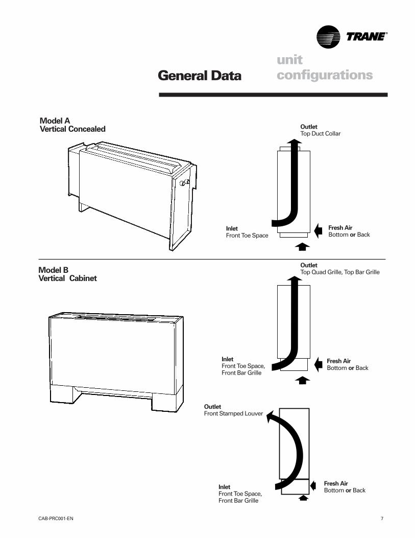
Model AVertical Concealed
Model BVertical Cabinet
InletFront Toe Space
Fresh AirBottom or Back
OutletTop Duct Collar
InletFront Toe Space,Front Bar Grille
Fresh AirBottom or Back
OutletTop Quad Grille, Top Bar Grille
unitconfigurations
InletFront Toe Space,Front Bar Grille
OutletFront Stamped Louver
Fresh AirBottom or Back
General Data
CAB-PRC001-EN8
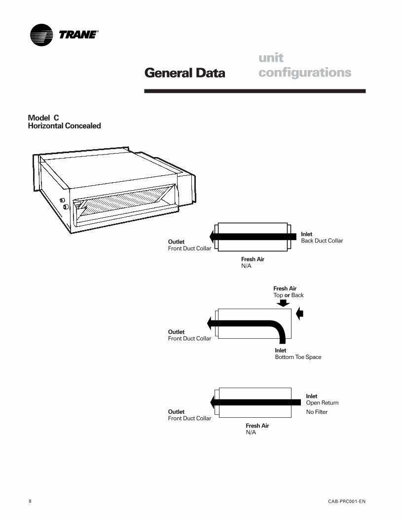
Model CHorizontal Concealed
unitconfigurations
InletBack Duct CollarOutlet
Front Duct Collar
Fresh AirN/A
Fresh AirN/A
OutletFront Duct Collar
InletOpen Return
No Filter
InletBottom Toe Space
Fresh AirTop or Back
OutletFront Duct Collar
General Data
CAB-PRC001-EN 9
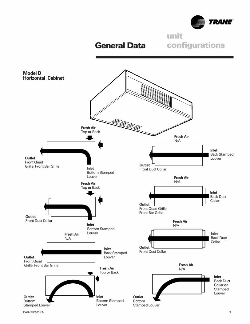
Model DHorizontal Cabinet
unitconfigurations
InletBottom StampedLouver
OutletFront QuadGrille, Front Bar Grille
Fresh AirTop or Back
Fresh AirTop or Back
InletBottom StampedLouver
OutletFront Duct Collar
InletBack StampedLouverOutlet
Front QuadGrille, Front Bar Grille
Fresh AirN/A
OutletFront Quad Grille,Front Bar Grille
Fresh AirN/A
InletBack DuctCollar
OutletBottomStamped Louver
InletBottom StampedLouver
Fresh AirTop or Back
Fresh AirN/A
InletBack DuctCollar
OutletFront Duct Collar
OutletBottomStamped Louver
Fresh AirN/A
InletBack DuctCollar orStampedLouver
OutletFront Duct Collar
Fresh AirN/A
InletBack StampedLouver
General Data
CAB-PRC001-EN10
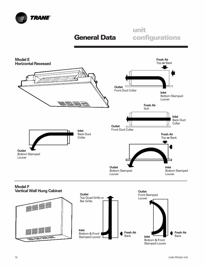
Model EHorizontal Recessed
InletBottom StampedLouver
Fresh AirTop or Back
OutletFront Duct Collar
unitconfigurations
Model FVertical Wall Hung Cabinet
InletBack DuctCollar
Fresh AirTop or Back
InletBottom StampedLouver
OutletFront Duct Collar
InletBack DuctCollar
Fresh AirN/A
OutletBottom StampedLouver
OutletBottom StampedLouver
InletBottom & FrontStamped Louver
OutletTop Quad Grille orBar Grille
Fresh AirBack
Fresh AirBackInlet
Bottom & FrontStamped Louver
OutletFront StampedLouver
General Data
CAB-PRC001-EN 11
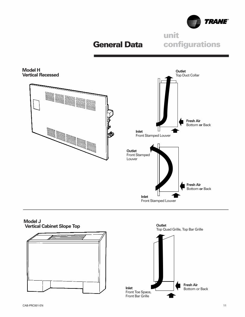
Model J Vertical Cabinet Slope Top
InletFront Toe Space,Front Bar Grille
Fresh AirBottom or Back
OutletTop Quad Grille, Top Bar Grille
unitconfigurations
Model HVertical Recessed
InletFront Stamped Louver
OutletFront StampedLouver
Fresh AirBottom or Back
InletFront Stamped Louver
OutletTop Duct Collar
Fresh AirBottom or Back
General Data
CAB-PRC001-EN12
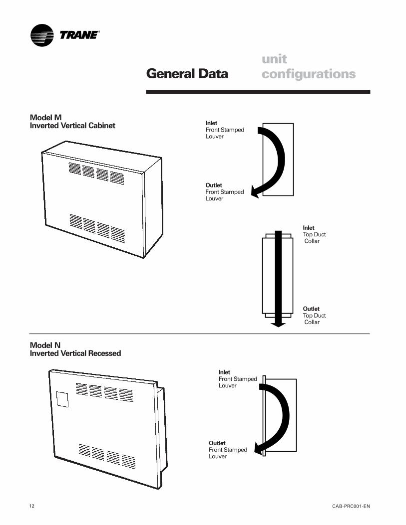
OutletFront StampedLouver
Model MInverted Vertical Cabinet Inlet
Front StampedLouver
OutletFront StampedLouver
Model NInverted Vertical Recessed
InletTop Duct Collar
OutletTop Duct Collar
InletFront StampedLouver
unitconfigurations
General Data
CAB-PRC001-EN 13
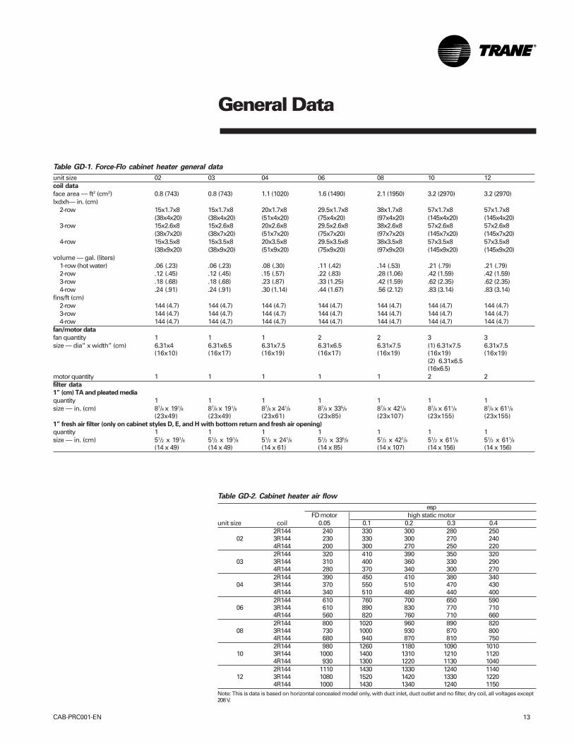
Table GD-1. Force-Flo cabinet heater general data
unit size 02 03 04 06 08 10 12coil data
face area — ft2 (cm2) 0.8 (743) 0.8 (743) 1.1 (1020) 1.6 (1490) 2.1 (1950) 3.2 (2970) 3.2 (2970)lxdxh— in. (cm)
2-row 15x1.7x8 15x1.7x8 20x1.7x8 29.5x1.7x8 38x1.7x8 57x1.7x8 57x1.7x8(38x4x20) (38x4x20) (51x4x20) (75x4x20) (97x4x20) (145x4x20) (145x4x20)
3-row 15x2.6x8 15x2.6x8 20x2.6x8 29.5x2.6x8 38x2.6x8 57x2.6x8 57x2.6x8(38x7x20) (38x7x20) (51x7x20) (75x7x20) (97x7x20) (145x7x20) (145x7x20)
4-row 15x3.5x8 15x3.5x8 20x3.5x8 29.5x3.5x8 38x3.5x8 57x3.5x8 57x3.5x8(38x9x20) (38x9x20) (51x9x20) (75x9x20) (97x9x20) (145x9x20) (145x9x20)
volume — gal. (liters)1-row (hot water) .06 (.23) .06 (.23) .08 (.30) .11 (.42) .14 (.53) .21 (.79) .21 (.79)2-row .12 (.45) .12 (.45) .15 (.57) .22 (.83) .28 (1.06) .42 (1.59) .42 (1.59)3-row .18 (.68) .18 (.68) .23 (.87) .33 (1.25) .42 (1.59) .62 (2.35) .62 (2.35)4-row .24 (.91) .24 (.91) .30 (1.14) .44 (1.67) .56 (2.12) .83 (3.14) .83 (3.14)
fins/ft (cm)2-row 144 (4.7) 144 (4.7) 144 (4.7) 144 (4.7) 144 (4.7) 144 (4.7) 144 (4.7)3-row 144 (4.7) 144 (4.7) 144 (4.7) 144 (4.7) 144 (4.7) 144 (4.7) 144 (4.7)4-row 144 (4.7) 144 (4.7) 144 (4.7) 144 (4.7) 144 (4.7) 144 (4.7) 144 (4.7)
fan/motor data
fan quantity 1 1 1 2 2 3 3size — dia” x width” (cm) 6.31x4 6.31x6.5 6.31x7.5 6.31x6.5 6.31x7.5 (1) 6.31x7.5 6.31x7.5
(16x10) (16x17) (16x19) (16x17) (16x19) (16x19) (16x19)(2) 6.31x6.5(16x6.5)
motor quantity 1 1 1 1 1 2 2filter data
1” (cm) TA and pleated media
quantity 1 1 1 1 1 1 1size — in. (cm) 87/8 x 191/8 87/8 x 191/8 87/8 x 241/8 87/8 x 335/8 87/8 x 421/8 87/8 x 611/8 87/8 x 611/8
(23x49) (23x49) (23x61) (23x85) (23x107) (23x155) (23x155)1” fresh air filter (only on cabinet styles D, E, and H with bottom return and fresh air opening)
quantity 1 1 1 1 1 1 1size — in. (cm) 51/2 x 191/8 51/2 x 191/8 51/2 x 241/8 51/2 x 335/8 51/2 x 421/8 51/2 x 611/8 51/2 x 611/8
(14 x 49) (14 x 49) (14 x 61) (14 x 85) (14 x 107) (14 x 156) (14 x 156)
Table GD-2. Cabinet heater air flow
espFD motor high static motor
unit size coil 0.05 0.1 0.2 0.3 0.42R144 240 330 300 280 250
02 3R144 230 330 300 270 2404R144 200 300 270 250 2202R144 320 410 390 350 320
03 3R144 310 400 360 330 2904R144 280 370 340 300 2702R144 390 450 410 380 340
04 3R144 370 550 510 470 4304R144 340 510 480 440 4002R144 610 760 700 650 590
06 3R144 610 890 830 770 7104R144 560 820 760 710 6602R144 800 1020 960 890 820
08 3R144 730 1000 930 870 8004R144 680 940 870 810 7502R144 980 1260 1180 1090 1010
10 3R144 1000 1400 1310 1210 11204R144 930 1300 1220 1130 10402R144 1110 1430 1330 1240 1140
12 3R144 1080 1520 1420 1330 12204R144 1000 1430 1340 1240 1150
Note: This is data is based on horizontal concealed model only, with duct inlet, duct outlet and no filter, dry coil, all voltages except208 V.
General Data
CAB-PRC001-EN14
Electric HeatAll Force-Flo™ cabinet heaters, exceptinverted models M and N, are availablewith electric heating coils as a standardoption.
Coil ConstructionElectric heat coils are open wire type witha nickel chromium element design.
Power SupplyUnits have single-point power since theelectric heating elements operate on linevoltage. Electric heat is available as208/60/1, 230/60/1, 277/60/1, 208/60/3, or480/60/3. Electric heat coils operate on thesame voltage as the unit, except for unitswith 480/60/3 electric heat. In this case, theunit operates at 277/60/1, thus requiring a4-wire supply. All fans and motors aresingle phase. In addition, all controloptions are 24-volt, utilizing a factory-installed transformer.
Power Supply LocationAll electric heat cabinet heaters have aterminal block for main power on theunit’s right-hand side.
Control TypeSingle-stage electric heat units arecontrolled by either Tracer ZN010, ZN510,or ZN520 control options. Two-stageelectric heat is controlled by the Tracer
ZN520 only. Both control options usePWM (pulse-width modulation) outputs tocalculate the electric heat output basedon the capacity request and the electricheat cycles per hour. For example, if theelectric heat cycles per hour is configuredfor six cycles (as Trane recommends) thecontroller bases the output on or off timeon six 10-minute periods. If the capacityrequest is 40%, the controller controls theelectric heat output on for approximatelyfour minutes each period.
Safety Features• All Force-Flo units with standard electric
heat are UL listed.• Units require only a single-point
electrical connection.• All electric heating coils are interlocked
with the fan motor switch. Therefore,electric heat operation is only possiblewhen the fan is running.
• Each unit has a transformer, eliminatingthe need for field installation of a step-down transformer.
• A unit mounted magnetic contactor(s) is(are) supplied on all unit voltages.
• A high temperature cutout with auto-matic reset de-energizes the electricheat in the event of an overheat condi-tion.
electric heat
General Data
CAB-PRC001-EN 15
Factory-Installed PipingPackagesForce-Flo cabinet heaters have standardpiping packages available as a factorybuilt and installed option. Factory builtassures all piping packages are fullytested under water for leaks and are builtwithin strict tolerances. Factory-installedmeans that supply and return pipes arethe only field connections required. Theinstaller doesn’t have to sweat connectpiping packages onto coil connections ina tight end pocket. Field connections arebrought to a point near the exterior of theunit for easy access.
Piping Package ComponentsForce-Flo piping packages consist of avariety of components for each applica-tion. The following section provides adetailed description of the piping compo-nents. Following this section are addi-tional illustrations and specifications.
Piping System/PlacementFactory piping packages are availablewith right or left hand connections. Asimple coil connection (a unit without apiping package) is also available in eithera right or left hand configuration for thoseapplications requiring field piping.
Interconnecting PipingInterconnecting piping refers to thecopper piping that attaches the coilconnections and all other componentssuch as control valves, end valves, etc.Piping is 1/2” nominal OD copper andextends near the unit exterior to one inletand one outlet connection.
Deluxe or Basic Piping PackageThe basic piping package includes onlythe main components of the pipingpackage: interconnecting piping, controlvalves, and end valves.
The deluxe piping package also includesa strainer on the entering water pipe andunions at the coil connections along withthe basic components listed above. Thestrainer body is cast brass construction,with a stainless steel mesh strainer thatis easily removed for cleaning. Theunions are forged brass construction andclose with a minimum amount of effort.
End ValvesEach piping package includes a ball valvefor the entering water pipe and one of thefollowing end valves on the leaving waterpipe: ball valve, manual circuit setter, oran auto circuit setter. These valves serveas the field connection points on all Force-Flo piping packages.
• Ball ValvesBall valves, also known as stop or endvalves, allow the unit to be cut off forservice purposes. These valves have atwo-inch handle that rotates 90° to a fullyopen position. The valve body is castbrass, and the ball is polished brass with aTeflon seat. Ball valves are available asend valves on both the entering andleaving water pipes.
Manual Circuit SetterIn lieu of a ball valve on the leaving waterpipe, a manual circuit setter, also knownas a manual flow control valve, acts asboth a flow setting device and a stopvalve. This valve allows water flowthrough the cabinet heater to be setquickly and accurately.
The manual circuit setter includesSchrader ports in the valve body. Theseports are used to measure the pressuredrop across the valve. This pressure dropcan be compared to factory suppliedcurves that relate the pressure drop to aspecific flow rate. This valve also has amemory stop that helps find the correctsetting quickly.
Auto Circuit SetterAn auto circuit setter is an automatic flowcontrol device available on the leavingwater pipe. The auto circuit setterincludes a cartridge within the valve bodythat is sized to allow a specific flow ratethrough the coil. This valve sets flowthrough the coil without any actionrequired by a system piping balancer. Theauto circuit setter is available on theleaving water pipe with a ball valve.
The auto circuit setter also includes twoP/T’s plugs in the valve body to allowmeasurement of the pressure droptemperature through the valve.
Control ValvesPiping packages are available with orwithout control valves. All control valveoptions are factory mounted and wired tothe Force-Flo unit controls.
piping packages
• Two-Way/Two-Position ValvesThese valves will either fully open orclose in response to a 24VAC signal fromthe Tracer ZN controller. Control valvesare direct-acting valves. The controlvalve is factory mounted in the leavingwater pipe downstream of the coil.Always use some means of relievingpump head pressure with two-way valveapplications. Normally open or normallyclosed valves are available.
• Three-Way/Two-Position ValvesThese valves will either allow full waterflow through the coil or divert the flowthrough a bypass line. The valvesrespond to a 24VAC signal from theTracer ZN controller. Control valves aredirect acting valves. All three-way valvepackages include a balance fitting in thebypass line to allow flow balancing in thebypass position. Three-way valves arefactory mounted in the leaving waterpipe downstream of the coil. Normallyopen or normally closed valves areavailable.
• Two-Way Modulating ValvesThese valves modulate the water flowthrough the coil in response to a signalfrom the Tracer ZN controller. Modulatingvalves are three-wire floating point equalpercentage valves, and are factorymounted in the leaving water pipedownstream of the coil.
• Three-Way Modulating ValvesThese valves modulate the water flowthrough the coil in response to a signalfrom the Tracer ZN controller. Three-wayvalves allow water that is directedthrough the coil to mix with waterdirected through the bypass line. Thismixture exits through the leaving waterpipe. Modulating valves are three-wirefloating point equal percentage valves,and are factory mounted in the leavingwater pipe downstream of the coil.
General Data
CAB-PRC001-EN16
piping packages
Piping Package Options
Automatic Circuit Setter (C)Manual
General Data
CAB-PRC001-EN 17
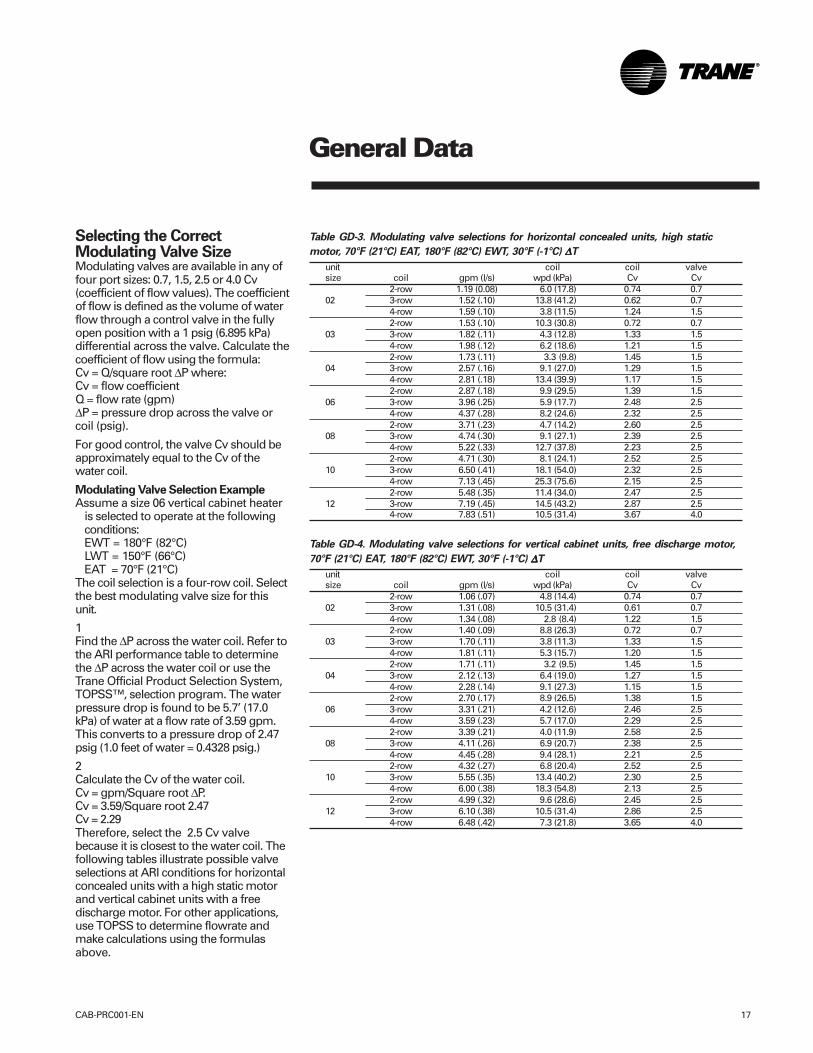
Selecting the CorrectModulating Valve SizeModulating valves are available in any offour port sizes: 0.7, 1.5, 2.5 or 4.0 Cv(coefficient of flow values). The coefficientof flow is defined as the volume of waterflow through a control valve in the fullyopen position with a 1 psig (6.895 kPa)differential across the valve. Calculate thecoefficient of flow using the formula:Cv = Q/square root ∆P where:Cv = flow coefficientQ = flow rate (gpm)∆P = pressure drop across the valve orcoil (psig).
For good control, the valve Cv should beapproximately equal to the Cv of thewater coil.
Modulating Valve Selection ExampleAssume a size 06 vertical cabinet heater
is selected to operate at the followingconditions:EWT = 180°F (82°C)LWT = 150°F (66°C)EAT = 70°F (21°C)
The coil selection is a four-row coil. Selectthe best modulating valve size for thisunit.
1Find the ∆P across the water coil. Refer tothe ARI performance table to determinethe ∆P across the water coil or use theTrane Official Product Selection System,TOPSS™, selection program. The waterpressure drop is found to be 5.7’ (17.0kPa) of water at a flow rate of 3.59 gpm.This converts to a pressure drop of 2.47psig (1.0 feet of water = 0.4328 psig.)
2Calculate the Cv of the water coil.Cv = gpm/Square root ∆P.Cv = 3.59/Square root 2.47Cv = 2.29Therefore, select the 2.5 Cv valvebecause it is closest to the water coil. Thefollowing tables illustrate possible valveselections at ARI conditions for horizontalconcealed units with a high static motorand vertical cabinet units with a freedischarge motor. For other applications,use TOPSS to determine flowrate andmake calculations using the formulasabove.
Table GD-3. Modulating valve selections for horizontal concealed units, high static
motor, 70°F (21°C) EAT, 180°F (82°C) EWT, 30°F (-1°C) ∆∆∆∆∆T
unit coil coil valvesize coil gpm (l/s) wpd (kPa) Cv Cv
2-row 1.19 (0.08) 6.0 (17.8) 0.74 0.702 3-row 1.52 (.10) 13.8 (41.2) 0.62 0.7
4-row 1.59 (.10) 3.8 (11.5) 1.24 1.52-row 1.53 (.10) 10.3 (30.8) 0.72 0.7
03 3-row 1.82 (.11) 4.3 (12.8) 1.33 1.54-row 1.98 (.12) 6.2 (18.6) 1.21 1.52-row 1.73 (.11) 3.3 (9.8) 1.45 1.5
04 3-row 2.57 (.16) 9.1 (27.0) 1.29 1.54-row 2.81 (.18) 13.4 (39.9) 1.17 1.52-row 2.87 (.18) 9.9 (29.5) 1.39 1.5
06 3-row 3.96 (.25) 5.9 (17.7) 2.48 2.54-row 4.37 (.28) 8.2 (24.6) 2.32 2.52-row 3.71 (.23) 4.7 (14.2) 2.60 2.5
08 3-row 4.74 (.30) 9.1 (27.1) 2.39 2.54-row 5.22 (.33) 12.7 (37.8) 2.23 2.52-row 4.71 (.30) 8.1 (24.1) 2.52 2.5
10 3-row 6.50 (.41) 18.1 (54.0) 2.32 2.54-row 7.13 (.45) 25.3 (75.6) 2.15 2.52-row 5.48 (.35) 11.4 (34.0) 2.47 2.5
12 3-row 7.19 (.45) 14.5 (43.2) 2.87 2.54-row 7.83 (.51) 10.5 (31.4) 3.67 4.0
Table GD-4. Modulating valve selections for vertical cabinet units, free discharge motor,
70°F (21°C) EAT, 180°F (82°C) EWT, 30°F (-1°C) ∆∆∆∆∆T
unit coil coil valvesize coil gpm (l/s) wpd (kPa) Cv Cv
2-row 1.06 (.07) 4.8 (14.4) 0.74 0.702 3-row 1.31 (.08) 10.5 (31.4) 0.61 0.7
4-row 1.34 (.08) 2.8 (8.4) 1.22 1.52-row 1.40 (.09) 8.8 (26.3) 0.72 0.7
03 3-row 1.70 (.11) 3.8 (11.3) 1.33 1.54-row 1.81 (.11) 5.3 (15.7) 1.20 1.52-row 1.71 (.11) 3.2 (9.5) 1.45 1.5
04 3-row 2.12 (.13) 6.4 (19.0) 1.27 1.54-row 2.28 (.14) 9.1 (27.3) 1.15 1.52-row 2.70 (.17) 8.9 (26.5) 1.38 1.5
06 3-row 3.31 (.21) 4.2 (12.6) 2.46 2.54-row 3.59 (.23) 5.7 (17.0) 2.29 2.52-row 3.39 (.21) 4.0 (11.9) 2.58 2.5
08 3-row 4.11 (.26) 6.9 (20.7) 2.38 2.54-row 4.45 (.28) 9.4 (28.1) 2.21 2.52-row 4.32 (.27) 6.8 (20.4) 2.52 2.5
10 3-row 5.55 (.35) 13.4 (40.2) 2.30 2.54-row 6.00 (.38) 18.3 (54.8) 2.13 2.52-row 4.99 (.32) 9.6 (28.6) 2.45 2.5
12 3-row 6.10 (.38) 10.5 (31.4) 2.86 2.54-row 6.48 (.42) 7.3 (21.8) 3.65 4.0
PerformanceData
CAB-PRC001-EN18
hot watercoils
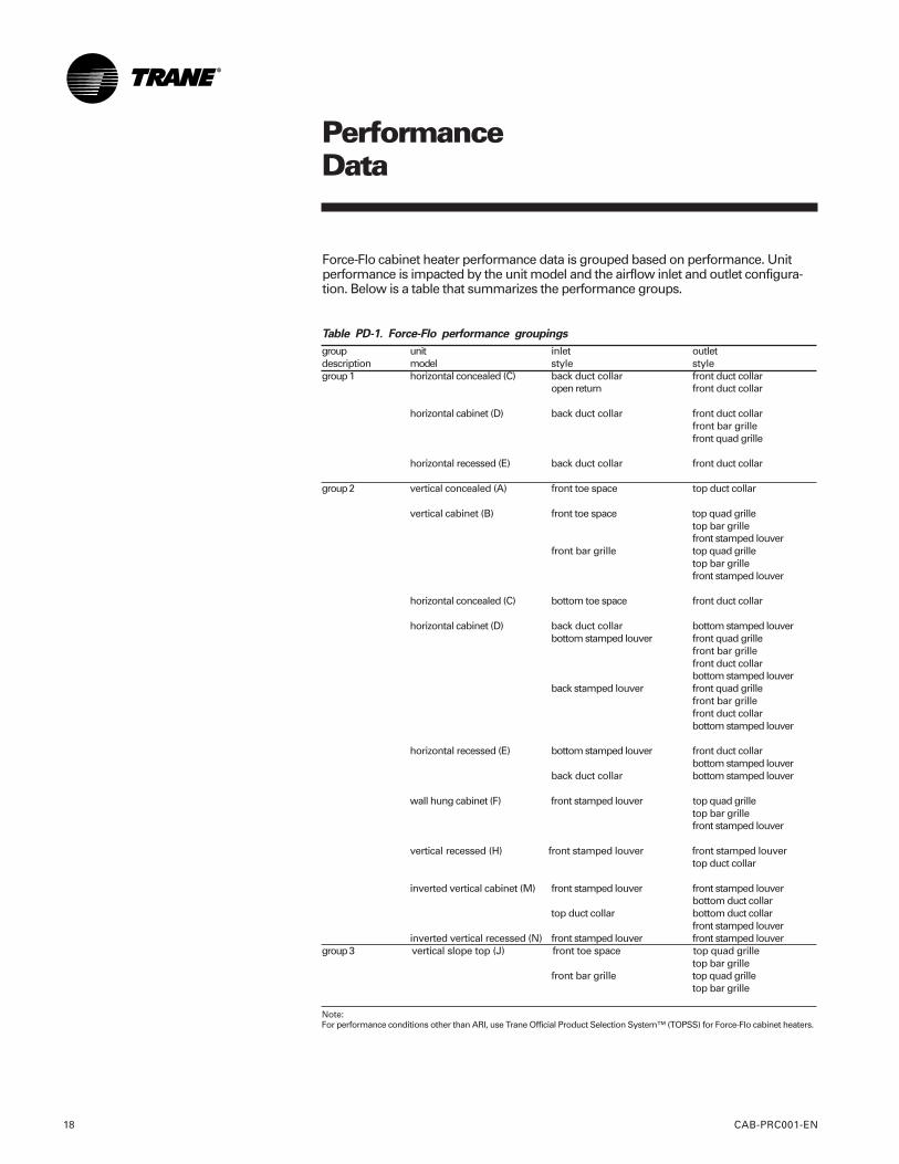
Force-Flo cabinet heater performance data is grouped based on performance. Unitperformance is impacted by the unit model and the airflow inlet and outlet configura-tion. Below is a table that summarizes the performance groups.
Table PD-1. Force-Flo performance groupings
group unit inlet outletdescription model style stylegroup 1 horizontal concealed (C) back duct collar front duct collar
open return front duct collar
horizontal cabinet (D) back duct collar front duct collarfront bar grillefront quad grille
horizontal recessed (E) back duct collar front duct collar
group 2 vertical concealed (A) front toe space top duct collar
vertical cabinet (B) front toe space top quad grilletop bar grillefront stamped louver
front bar grille top quad grilletop bar grillefront stamped louver
horizontal concealed (C) bottom toe space front duct collar
horizontal cabinet (D) back duct collar bottom stamped louverbottom stamped louver front quad grille
front bar grillefront duct collarbottom stamped louver
back stamped louver front quad grillefront bar grillefront duct collarbottom stamped louver
horizontal recessed (E) bottom stamped louver front duct collarbottom stamped louver
back duct collar bottom stamped louver
wall hung cabinet (F) front stamped louver top quad grilletop bar grillefront stamped louver
vertical recessed (H) front stamped louver front stamped louvertop duct collar
inverted vertical cabinet (M) front stamped louver front stamped louverbottom duct collar
top duct collar bottom duct collarfront stamped louver
inverted vertical recessed (N) front stamped louver front stamped louvergroup 3 vertical slope top (J) front toe space top quad grille
top bar grillefront bar grille top quad grille
top bar grille
Note:For performance conditions other than ARI, use Trane Official Product Selection System™ (TOPSS) for Force-Flo cabinet heaters.
PerformanceData
CAB-PRC001-EN 19
hot watercoils
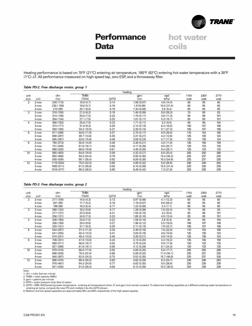
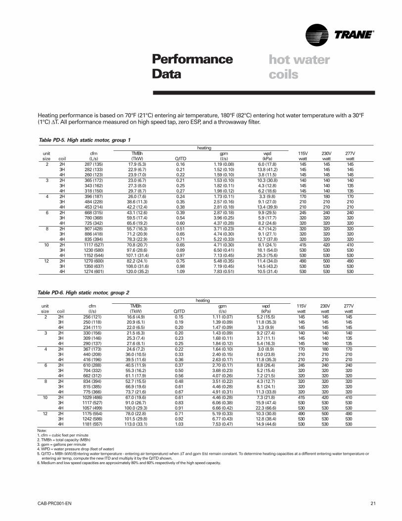
Heating performance is based on 70°F (21°C) entering air temperature, 180°F (82°C) entering hot water temperature with a 30°F(1°C) ∆T. All performance measured on high speed tap, zero ESP, and a throwaway filter.
Table PD-3. Free discharge motor, group 2
heatingunit cfm TMBh gpm wpd 115V 230V 277Vsize coil (l/s) (TkW) Q/ITD (l/s) (kPa) watt watt watt 2 2-row 211 (100) 14.5 (4.3) 0.13 0.97 (0.06) 4.1 (12.3) 60 95 65
3-row 201 (95) 17.7 (5.2) 0.16 1.18 (0.07) 8.8 (26.2) 60 95 654-row 188 (89) 18.3 (5.4) 0.17 1.22 (0.08) 2.4 (7.1) 60 95 65
3 2-row 280 (132) 19.2 (5.6) 0.17 1.28 (0.08) 7.5 (22.4) 70 80 833-row 277 (131) 23.3 (6.8) 0.21 1.55 (0.10) 3.2 (9.5) 85 89 1014-row 256 (121) 24.8 (7.3) 0.23 1.65 (0.10) 4.5 (13.4) 85 89 101
4 2-row 349 (165) 23.8 (7.0) 0.22 1.58 (0.10) 2.8 (8.3) 95 96 1043-row 338 (159) 29.4 (8.6) 0.27 1.96 (0.12) 5.5 (16.5) 100 107 1064-row 320 (151) 31.7 (9.3) 0.29 2.11 (0.13) 7.9 (23.7) 100 107 106
6 2-row 544 (257) 37.4 (11.0) 0.34 2.49 (0.16) 7.6 (22.8) 110 154 1653-row 541 (255) 45.4 (13.3) 0.41 3.03 (0.19) 3.6 (10.6) 125 130 1244-row 510 (241) 49.4 (14.5) 0.45 3.29 (0.21) 4.8 (14.5) 125 130 124
8 2-row 706 (331) 47.0 (13.8) 0.43 3.13 (0.20) 3.4 (10.2) 135 150 1593-row 659 (311) 56.8 (16.7) 0.52 3.79 (0.24) 5.9 (17.8) 120 123 1334-row 627 (296) 61.8 (18.1) 0.56 4.12 (0.26) 8.1 (24.3) 120 123 133
10 2-row 879 (415) 60.0 (17.6) 0.55 4.00 (0.25) 5.9 (17.7) 205 250 2693-row 886 (420) 76.4 (22.4) 0.69 5.09 (0.32) 11.4 (34.1) 225 237 2304-row 840 (397) 82.8 (24.3) 0.75 5.52 (0.35) 15.7 (46.8) 225 237 230
12 2-row 996 (470) 69.4 (20.3) 0.63 4.62 (0.29) 8.3 (24.7) 230 246 2633-row 976 (461) 84.3 (24.8) 0.77 5.62 (0.35) 9.0 (26.8) 220 230 2394-row 921 (435) 91.8 (26.4) 0.83 6.12 (0.39) 10.2 (30.5) 220 230 239
Note:1. cfm = cubic feet per minute2. TMBh = total capacity (MBh)3. gpm = gallons per minute4. WPD = water pressure drop (feet of water)5. Q/ITD = MBh (kW)/(entering water temperature - entering air temperature) when ∆T and gpm (L/s) remain constant. To determine heating capacities at a different entering water temperature or
entering air temp, compute the new ITD and multiply it by the Q/ITD shown.6. Medium and low speed capacities are approximately 80% and 60% respectively of the high speed capacity.
Table PD-2. Free discharge motor, group 1
heatingunit cfm TMBh gpm wpd 115V 230V 277Vsize coil (l/s) (TkW) Q/ITD (l/s) (kPa) watt watt watt 2 2-row 240 (113) 15.9 (4.7) 0.14 1.06 (0.07) 4.8 (14.4) 60 95 65
3-row 230 ( 108) 19.6 (5.7) 0.18 1.31(0.08) 10.5 (31.4) 60 95 654-row 210 (99) 20.1 (6.0) 0.18 1.34 (0.08) 2.8 (8.4) 60 95 65
3 2-row 318 (150) 21.0 (6.2) 0.19 1.40 (0.09) 8.8 (26.3) 70 80 833-row 314 (148) 25.6 (7.5) 0.23 1.70 (0.11) 3.8 (11.3) 85 89 1014-row 284 (134) 27.1 (7.9) 0.25 1.81 (0.11) 5.3 (15.7) 85 89 101
4 2-row 388 (183) 25.6 (7.5) 0.23 1.71 (0.11) 3.2 (9.5) 95 96 1043-row 374 (177) 31.8 (9.3) 0.29 2.12 (0.13) 6.4 (19.0) 100 107 1064-row 350 (165) 34.2 (10.0) 0.31 2.28 (0.14) 9.1 (27.3) 100 107 106
6 2-row 611 (289) 40.6 (11.9) 0.37 2.70 (0.17) 8.9 (26.5) 110 154 1653-row 608 (287) 49.7 (14.6) 0.45 3.31 (0.21) 4.2 (12.6) 125 130 1244-row 565 (267) 53.8 (15.8) 0.49 3.59 (0.23) 5.7 (17.0) 125 130 124
8 2-row 790 (373) 50.9 (14.9) 0.46 3.39 (0.21) 4.0 (11.9) 135 150 1593-row 731 (345) 61.6 (18.1) 0.56 4.11 (0.26) 6.9 (20.7) 120 123 1334-row 688 (325) 66.8 (19.6) 0.61 4.45 (0.28) 9.4 (28.1) 120 123 133
10 2-row 980 (463) 64.8 (19.0) 0.59 4.32 (0.27) 6.8 (20.4) 205 250 2693-row 992 (468) 83.3 (24.4) 0.76 5.55 (0.35) 13.4 (40.2) 225 237 2304-row 930 (439) 90.1 (26.4) 0.82 6.00 (0.38) 18.3 (54.8) 225 237 230
12 2-row 1110 (524) 75.0 (22.0) 0.68 4.99 (0.32) 9.6 (28.6) 230 246 2633-row 1082 (511) 91.5 (26.8) 0.83 6.10 (0.38) 10.5 (31.4) 220 230 2394-row 1010 (477) 99.3 (28.5) 0.90 6.48 (0.42) 7.3 (21.8) 220 230 239
PerformanceData
CAB-PRC001-EN20
hot watercoils
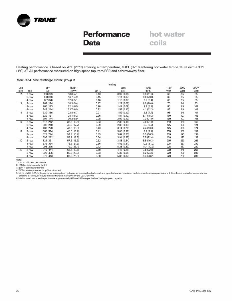
Heating performance is based on 70°F (21°C) entering air temperature, 180°F (82°C) entering hot water temperature with a 30°F(1°C) ∆T. All performance measured on high speed tap, zero ESP, and a throwaway filter.
Table PD-4. Free discharge motor, group 3
heatingunit cfm TMBh gpm WPD 115V 230V 277Vsize coil (l/s) (TkW) Q/ITD (l/s) (kPa) watt watt watt 2 2-row 198 (93) 13.8 (4.1) 0.13 0.92 (0.06) 3.8 (11.3) 60 95 65
3-row 188 (90) 16.7 (4.9) 0.15 1.11 (0.07) 8.0 (23.8) 60 95 654-row 177 (84) 17.3 (5.1) 0.16 1.16 (0.07) 2.2 (6.4) 60 95 65
3 2-row 262 (124) 18.3 (5.4) 0.17 1.22 (0.08) 6.9 (20.6) 70 80 833-row 260 (123) 22.1 (6.5) 0.20 1.47 (0.09) 2.9 (8.7) 85 89 1014-row 242 (114) 23.7 (6.9) 0.22 1.58 (0.10) 4.1 (12.3) 85 89 101
4 2-row 330 (156) 22.8 (6.7) 0.21 1.52 (0.10) 2.6 (7.7) 95 96 1043-row 320 (151) 28.1 (8.2) 0.26 1.87 (0.12) 5.1 (15.2) 100 107 1064-row 304 (144) 30.3 (8.9) 0.28 2.02 (0.13) 7.3 (21.9) 100 107 106
6 2-row 512 (242) 35.8 (10.5) 0.33 2.38 (0.15) 7.0 (21.0) 110 154 1653-row 508 (240) 43.3 (12.7) 0.39 2.88 (0.18) 3.3 (9.7) 125 130 1244-row 483 (228) 47.2 (13.8) 0.43 3.14 (0.20) 4.4 (13.3) 125 130 124
8 2-row 665 (314) 45.0 (13.2) 0.41 3.00 (0.19) 3.2 (9.4) 135 150 1593-row 623 (294) 54.3 (15.9) 0.49 3.62 (0.23) 5.5 (16.3) 120 123 1334-row 596 (282) 59.2 (17.3) 0.54 3.94 (0.25) 7.5 (22.4) 120 123 133
10 2-row 829 (391) 57.5 (16.9) 0.52 3.83 (0.24) 5.5 (16.3) 205 250 2693-row 835 (394) 72.9 (21.3) 0.66 4.86 (0.31) 10.5 (31.2) 225 237 2304-row 796 (376) 79.0 (23.1) 0.72 5.26 (0.33) 14.4 (42.9) 225 237 230
12 2-row 940 (444) 66.5 (19.5) 0.60 4.43 (0.28) 7.6 (22.8) 230 246 2633-row 923 (436) 80.6 (23.6) 0.73 5.37 (0.34) 8.2 (24.6) 220 230 2394-row 876 (413) 87.9 (25.8) 0.80 5.86 (0.37) 9.4 (28.2) 220 230 239
Note:1. cfm = cubic feet per minute2. TMBh = total capacity (MBh)3. gpm = gallons per minute4. WPD = Water pressure drop (feet of water)5. Q/ITD = MBh (kW)/(entering water temperature - entering air temperature) when ∆T and gpm (l/s) remain constant. To determine heating capacities at a different entering water temperature or
entering air temp, compute the new ITD and multiply it by the Q/ITD shown.6. Medium and low speed capacities are approximately 80% and 60% respectively of the high speed capacity.
PerformanceData
CAB-PRC001-EN 21
hot watercoils
Heating performance is based on 70°F (21°C) entering air temperature, 180°F (82°C) entering hot water temperature with a 30°F(1°C) ∆T. All performance measured on high speed tap, zero ESP, and a throwaway filter.
Table PD-6. High static motor, group 2
heatingunit cfm TMBh gpm wpd 115V 230V 277Vsize coil (l/s) (TkW) Q/ITD (l/s) (kPa) watt watt watt 2 2H 256 (121) 16.6 (4.9) 0.15 1.11 (0.07) 5.2 (15.5) 145 145 145
3H 250 (118) 20.9 (6.1) 0.19 1.39 (0.09) 11.8 (35.3) 145 145 1454H 234 (111) 22.0 (6.5) 0.20 1.47 (0.09) 3.3 (9.9) 145 145 145
3 2H 330 (156) 21.5 (6.3) 0.20 1.43 (0.09) 9.2 (27.4) 140 140 1403H 309 (146) 25.3 (7.4) 0.23 1.68 (0.11) 3.7 (11.1) 145 140 1354H 290 (137) 27.6 (8.1) 0.25 1.84 (0.12) 5.4 (16.3) 145 140 135
4 2H 367 (173) 24.6 (7.2) 0.22 1.64 (0.10) 3.0 (8.9) 170 180 1703H 440 (208) 36.0 (10.5) 0.33 2.40 (0.15) 8.0 (23.8) 210 210 2104H 416 (196) 39.5 (11.6) 0.36 2.63 (0.17) 11.8 (35.3) 210 210 210
6 2H 610 (288) 40.5 (11.9) 0.37 2.70 (0.17) 8.8 (26.4) 245 240 2403H 704 (332) 55.3 (16.2) 0.50 3.68 (0.23) 5.2 (15.4) 320 320 3204H 662 (312) 61.1 (17.9) 0.56 4.07 (0.26) 7.2 (21.5) 320 320 320
8 2H 834 (394) 52.7 (15.5) 0.48 3.51 (0.22) 4.3 (12.7) 320 320 3203H 815 (385) 66.9 (19.6) 0.61 4.46 (0.28) 8.1 (24.1) 320 320 3204H 775 (366) 73.7 (21.6) 0.67 4.91 (0.31) 11.3 (33.8) 320 320 320
10 2H 1029 (486) 67.0 (19.6) 0.61 4.46 (0.28) 7.3 (21.8) 415 420 4103H 1117 (527) 91.0 (26.7) 0.83 6.06 (0.38) 15.9 (47.4) 530 530 5304H 1057 (499) 100.0 (29.3) 0.91 6.66 (0.42) 22.3 (66.6) 530 530 530
12 2H 1175 (554) 78.0 (22.8) 0.71 5.19 (0.33) 10.3 (30.8) 490 500 4903H 1242 (586) 101.5 (29.8) 0.92 6.77 (0.43) 12.8 (38.4) 530 530 5304H 1181 (557) 113.0 (33.1) 1.03 7.53 (0.47) 14.9 (44.6) 530 530 530
Note:1. cfm = cubic feet per minute2. TMBh = total capacity (MBh)3. gpm = gallons per minute4. WPD = water pressure drop (feet of water)5. Q/ITD = MBh (kW)/(Entering water temperature - entering air temperature) when ∆T and gpm (l/s) remain constant. To determine heating capacities at a different entering water temperature or
entering air temp, compute the new ITD and multiply it by the Q/ITD shown.6. Medium and low speed capacities are approximately 80% and 60% respectively of the high speed capacity.
Table PD-5. High static motor, group 1
heatingunit cfm TMBh gpm wpd 115V 230V 277Vsize coil (L/s) (TkW) Q/ITD (l/s) (kPa) watt watt watt 2 2H 287 (135) 17.9 (5.3) 0.16 1.19 (0.08) 6.0 (17.8) 145 145 145
3H 282 (133) 22.9 (6.7) 0.21 1.52 (0.10) 13.8 (41.2) 145 145 1454H 260 (123) 23.9 (7.0) 0.22 1.59 (0.10) 3.8 (11.5) 145 145 145
3 2H 365 (172) 23.0 (6.7) 0.21 1.53 (0.10) 10.3 (30.8) 140 140 1403H 343 (162) 27.3 (8.0) 0.25 1.82 (0.11) 4.3 (12.8) 145 140 1354H 318 (150) 29.7 (8.7) 0.27 1.98 (0.12) 6.2 (18.6) 145 140 135
4 2H 396 (187) 26.0 (7.6) 0.24 1.73 (0.11) 3.3 (9.8) 170 180 1703H 484 (228) 38.6 (11.3) 0.35 2.57 (0.16) 9.1 (27.0) 210 210 2104H 453 (214) 42.2 (12.4) 0.38 2.81 (0.18) 13.4 (39.9) 210 210 210
6 2H 668 (315) 43.1 (12.6) 0.39 2.87 (0.18) 9.9 (29.5) 245 240 2403H 780 (368) 59.5 (17.4) 0.54 3.96 (0.25) 5.9 (17.7) 320 320 3204H 725 (342) 65.6 (19.2) 0.60 4.37 (0.28) 8.2 (24.6) 320 320 320
8 2H 907 (428) 55.7 (16.3) 0.51 3.71 (0.23) 4.7 (14.2) 320 320 3203H 886 (418) 71.2 (20.9) 0.65 4.74 (0.30) 9.1 (27.1) 320 320 3204H 835 (394) 78.3 (22.9) 0.71 5.22 (0.33) 12.7 (37.8) 320 320 320
10 2H 1117 (527) 70.8 (20.7) 0.65 4.71 (0.30) 8.1 (24.1) 415 420 4103H 1230 (580) 97.6 (28.6) 0.89 6.50 (0.41) 18.1 (54.0) 530 530 5304H 1152 (544) 107.1 (31.4) 0.97 7.13 (0.45) 25.3 (75.6) 530 530 530
12 2H 1270 (600) 82.2 (24.1) 0.75 5.48 (0.35) 11.4 (34.0) 490 500 4903H 1350 (637) 108.0 (31.6) 0.98 7.19 (0.45) 14.5 (43.2) 530 530 5304H 1274 (601) 120.0 (35.2) 1.09 7.83 (0.51) 10.5 (31.4) 530 530 530
PerformanceData
CAB-PRC001-EN22
steamcoils
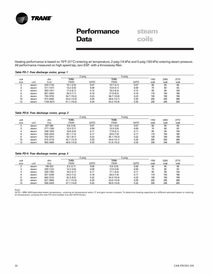
Heating performance is based on 70°F (21°C) entering air temperature, 2 psig (14 kPa) and 5 psig (103 kPa) entering steam pressure.All performance measured on high speed tap, zero ESP, with a throwaway filter.
Table PD-7. Free discharge motor, group 1
2 psig 5 psigunit cfm TMBh TMBh 115V 230V 277Vsize coil (L/s) (TkW) Q/ITD (TkW) Q/ITD watt watt watt
2 steam 234 (110) 10.1 (2.9) 0.07 10.7 (3.1) 0.07 60 95 653 steam 311 (147) 13.2 (3.9) 0.09 13.9 (4.1) 0.09 70 80 834 steam 383 (181) 17.3 (5.1) 0.12 18.3 (5.4) 0.12 95 96 1046 steam 601 (284) 26.3 (7.7) 0.18 27.9 (8.2) 0.18 110 154 1658 steam 783 (370) 34.7 (10.2) 0.23 36.7 (10.8) 0.23 135 150 15910 steam 974 (460) 44.0 (12.9) 0.30 46.6 (13.7) 0.30 205 250 26912 steam 1104 (521) 51.1 (15.0) 0.34 54.2 (15.9) 0.35 230 246 263
Table PD-8. Free discharge motor, group 2
2 psig 5 psigunit cfm TMBh TMBh 115V 230V 277Vsize coil (l/s) (TkW) Q/ITD (TkW) Q/ITD watt watt watt
2 steam 207 (98) 9.6 (2.8) 0.07 10.1 (3.0) 0.07 60 95 653 steam 277 (130) 12.5 (3.7) 0.08 13.3 (3.9) 0.08 70 80 834 steam 346 (163) 16.6 (4.9) 0.11 17.6 (5.1) 0.11 95 96 1046 steam 538 (254) 25.1 (7.4) 0.17 26.6 (7.8) 0.17 110 154 1658 steam 702 (331) 33.1 (9.7) 0.22 35.1 (10.3) 0.22 135 150 15910 steam 875 (413) 42.1 (12.3) 0.28 44.6 (13.1) 0.28 205 250 26912 steam 993 (469) 48.9 (14.3) 0.33 51.8 (15.2) 0.33 230 246 263
Table PD-9. Free discharge motor, group 3
2 psig 5 psigunit cfm TMBh TMBh 115V 230V 277Vsize coil (l/s) (TkW) Q/ITD (TkW) Q/ITD watt watt watt
2 steam 195 (92) 9.3 (2.7) 0.06 9.9 (2.9) 0.06 60 95 653 steam 259 (122) 12.2 (3.6) 0.08 12.9 (3.8) 0.08 70 80 834 steam 328 (155) 16.2 (4.7) 0.11 17.1 (5.0) 0.11 95 96 1046 steam 507 (239) 24.5 (7.2) 0.16 26.0 (7.6) 0.17 110 154 1658 steam 662 (312) 32.3 (9.5) 0.22 34.3 (10.0) 0.22 135 150 15910 steam 827 (390) 41.1 (12.0) 0.28 43.6 (12.8) 0.28 205 250 26912 steam 938 (443) 47.7 (14.0) 0.32 50.6 (14.8) 0.32 230 246 263
Note:Q/ITD = MBh (kW)/(saturated steam temperature - entering air temperature) when ∆T and gpm remain constant. To determine heating capacities at a different saturated steam or enteringair temperature, compute the new ITD and multiply it by the Q/ITD shown.
PerformanceData
CAB-PRC001-EN 23
steamcoils
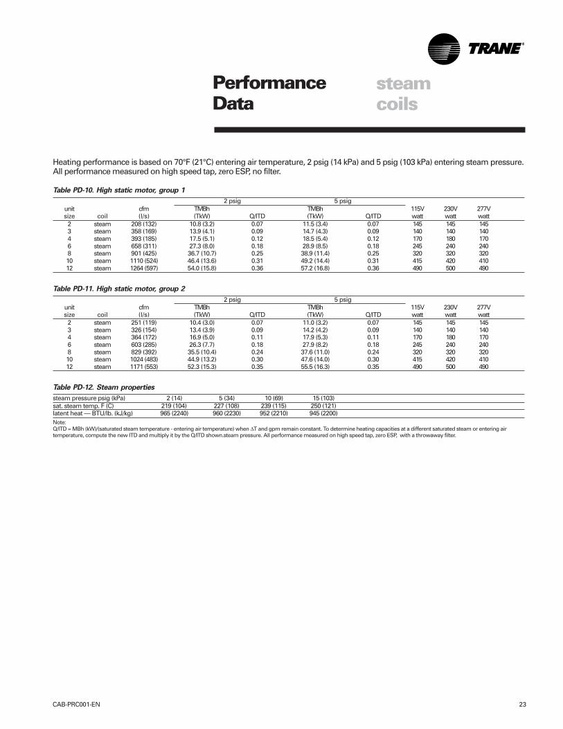
Heating performance is based on 70°F (21°C) entering air temperature, 2 psig (14 kPa) and 5 psig (103 kPa) entering steam pressure.All performance measured on high speed tap, zero ESP, no filter.
Table PD-10. High static motor, group 1
2 psig 5 psigunit cfm TMBh TMBh 115V 230V 277Vsize coil (l/s) (TkW) Q/ITD (TkW) Q/ITD watt watt watt
2 steam 208 (132) 10.8 (3.2) 0.07 11.5 (3.4) 0.07 145 145 1453 steam 358 (169) 13.9 (4.1) 0.09 14.7 (4.3) 0.09 140 140 1404 steam 393 (185) 17.5 (5.1) 0.12 18.5 (5.4) 0.12 170 180 1706 steam 658 (311) 27.3 (8.0) 0.18 28.9 (8.5) 0.18 245 240 2408 steam 901 (425) 36.7 (10.7) 0.25 38.9 (11.4) 0.25 320 320 32010 steam 1110 (524) 46.4 (13.6) 0.31 49.2 (14.4) 0.31 415 420 41012 steam 1264 (597) 54.0 (15.8) 0.36 57.2 (16.8) 0.36 490 500 490
Table PD-11. High static motor, group 2
2 psig 5 psigunit cfm TMBh TMBh 115V 230V 277Vsize coil (l/s) (TkW) Q/ITD (TkW) Q/ITD watt watt watt
2 steam 251 (119) 10.4 (3.0) 0.07 11.0 (3.2) 0.07 145 145 1453 steam 326 (154) 13.4 (3.9) 0.09 14.2 (4.2) 0.09 140 140 1404 steam 364 (172) 16.9 (5.0) 0.11 17.9 (5.3) 0.11 170 180 1706 steam 603 (285) 26.3 (7.7) 0.18 27.9 (8.2) 0.18 245 240 2408 steam 829 (392) 35.5 (10.4) 0.24 37.6 (11.0) 0.24 320 320 32010 steam 1024 (483) 44.9 (13.2) 0.30 47.6 (14.0) 0.30 415 420 41012 steam 1171 (553) 52.3 (15.3) 0.35 55.5 (16.3) 0.35 490 500 490
Table PD-12. Steam properties
steam pressure psig (kPa) 2 (14) 5 (34) 10 (69) 15 (103)sat. steam temp. F (C) 219 (104) 227 (108) 239 (115) 250 (121)latent heat — BTU/lb. (kJ/kg) 965 (2240) 960 (2230) 952 (2210) 945 (2200)Note:Q/ITD = MBh (kW)/(saturated steam temperature - entering air temperature) when ∆T and gpm remain constant. To determine heating capacities at a different saturated steam or entering airtemperature, compute the new ITD and multiply it by the Q/ITD shown.steam pressure. All performance measured on high speed tap, zero ESP, with a throwaway filter.
Controls
CAB-PRC001-EN24
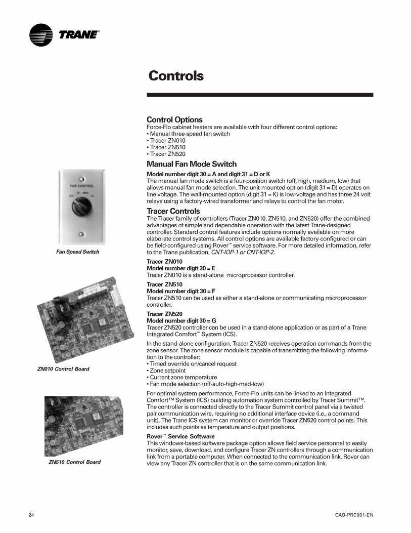
ZN010 Control Board
ZN510 Control Board
Control OptionsForce-Flo cabinet heaters are available with four different control options:• Manual three-speed fan switch• Tracer ZN010• Tracer ZN510• Tracer ZN520
Manual Fan Mode Switch
Model number digit 30 = A and digit 31 = D or KThe manual fan mode switch is a four-position switch (off, high, medium, low) thatallows manual fan mode selection. The unit-mounted option (digit 31 = D) operates online voltage. The wall-mounted option (digit 31 = K) is low-voltage and has three 24 voltrelays using a factory-wired transformer and relays to control the fan motor.
Tracer ControlsThe Tracer family of controllers (Tracer ZN010, ZN510, and ZN520) offer the combinedadvantages of simple and dependable operation with the latest Trane-designedcontroller. Standard control features include options normally available on moreelaborate control systems. All control options are available factory-configured or canbe field-configured using Rover™ service software. For more detailed information, referto the Trane publication, CNT-IOP-1 or CNT-IOP-2.
Tracer ZN010Model number digit 30 = ETracer ZN010 is a stand-alone microprocessor controller.
Tracer ZN510Model number digit 30 = FTracer ZN510 can be used as either a stand-alone or communicating microprocessorcontroller.
Tracer ZN520Model number digit 30 = GTracer ZN520 controller can be used in a stand-alone application or as part of a TraneIntegrated Comfort™ System (ICS).
In the stand-alone configuration, Tracer ZN520 receives operation commands from thezone sensor. The zone sensor module is capable of transmitting the following informa-tion to the controller:• Timed override on/cancel request• Zone setpoint• Current zone temperature• Fan mode selection (off-auto-high-med-low)
For optimal system performance, Force-Flo units can be linked to an IntegratedComfort™ System (ICS) building automation system controlled by Tracer Summit™.The controller is connected directly to the Tracer Summit control panel via a twistedpair communication wire, requiring no additional interface device (i.e., a commandunit). The Trane ICS system can monitor or override Tracer ZN520 control points. Thisincludes such points as temperature and output positions.
Rover™ Service SoftwareThis windows-based software package option allows field service personnel to easilymonitor, save, download, and configure Tracer ZN controllers through a communicationlink from a portable computer. When connected to the communication link, Rover canview any Tracer ZN controller that is on the same communication link.
Fan Speed Switch
Controls
CAB-PRC001-EN 25
sequence ofoperation
Sequence of Operation
Fan Speed SwitchOff: Fan is turned off, two-positiondamper option spring-returns closed.
High, Medium, Low: Fan runs continu-ously at the selected speed. The two-position damper option opens to anadjustable mechanical stop position.
Tracer ZN010 and ZN510Off: Fan is off; control valves and fresh airdamper option close.
Auto (Fan Cycling): Fan and fresh airdamper cycle with control valve option tomaintain setpoint temperature. In heatingmode it cycles from off to low (factorydefault that can be field-adjusted usingRover service software). When heating isnot required, the fan is off and the freshair damper option closes. The fan can alsobe field-configured (using Rover) to run ata user-defined speed when the fan speedswitch is in the auto position.
Low, Medium, High (Continuous Fan): Fanoperates continuously while control valve
option cycles to maintain setpointtemperature. Fresh air damper option isopen.
Tracer ZN520Off: Fan is off; control valve options andfresh air damper options close.
Auto: Fan speed control in the autosetting allows the modulating (three-wirefloating point) control valve option andthree-speed fan to work cooperatively tomeet precise capacity requirements,while minimizing fan speed (motor/energy/acoustics) and valve position(pump energy). As the capacity require-ment increases at low fan speed, thewater valve opens. When the low fanspeed capacity switch point is reached,the fan switches to medium speed andthe water valve repositions to maintain anequivalent capacity. The reverse se-quence takes place with a decrease inrequired capacity.
Low, Medium, High: The fan will runcontinuously at the selected speed andthe valve option will cycle to meetsetpoint.
Controls
CAB-PRC001-EN26
generalinformation
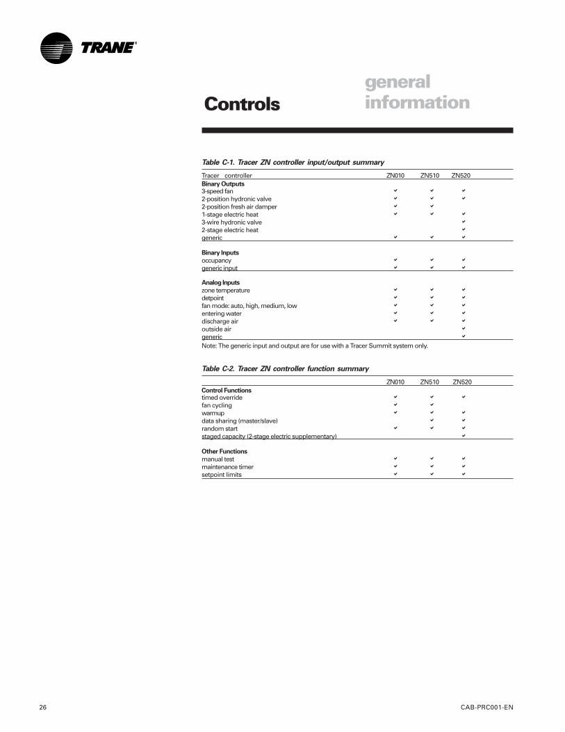
Table C-1. Tracer ZN controller input/output summary
Tracer controller ZN010 ZN510 ZN520Binary Outputs3-speed fan � � �
2-position hydronic valve � � �
2-position fresh air damper � �
1-stage electric heat � � �
3-wire hydronic valve �
2-stage electric heat �
generic � � �
Binary Inputs
occupancy � � �
generic input � � �
Analog Inputs
zone temperature � � �
detpoint � � �
fan mode: auto, high, medium, low � � �
entering water � � �
discharge air � � �
outside air �
generic �
Note: The generic input and output are for use with a Tracer Summit system only.
Table C-2. Tracer ZN controller function summary
ZN010 ZN510 ZN520Control Functionstimed override � � �
fan cycling � �
warmup � � �
data sharing (master/slave) � �
random start � � �
staged capacity (2-stage electric supplementary) �
Other Functions
manual test � � �
maintenance timer � � �
setpoint limits � � �
Controls
CAB-PRC001-EN 27
zone sensoroptions
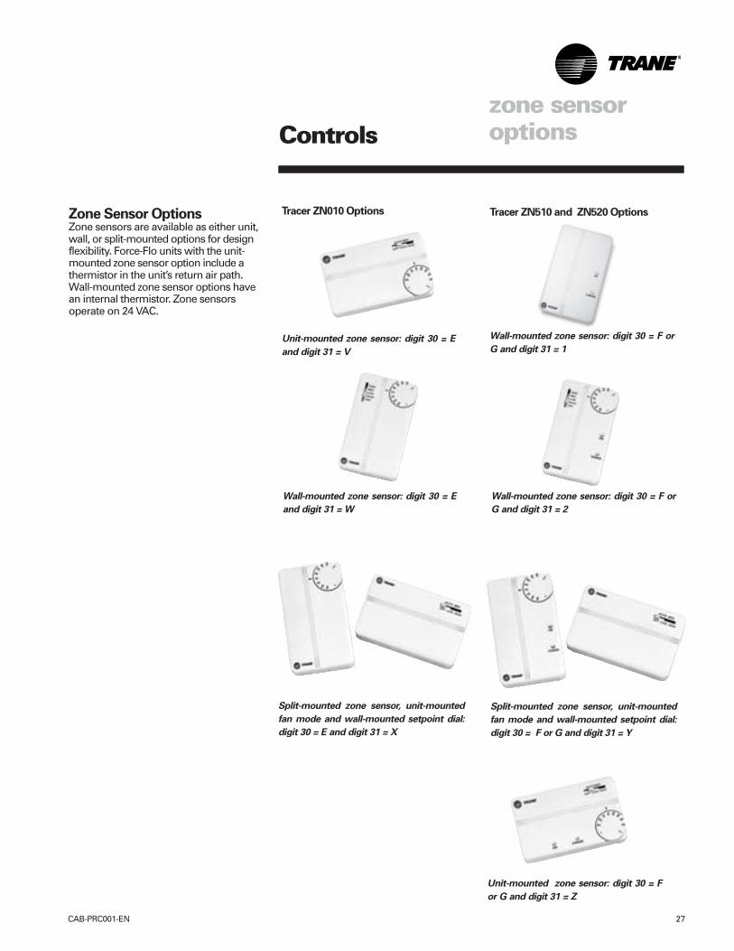
Zone Sensor OptionsZone sensors are available as either unit,wall, or split-mounted options for designflexibility. Force-Flo units with the unit-mounted zone sensor option include athermistor in the unit’s return air path.Wall-mounted zone sensor options havean internal thermistor. Zone sensorsoperate on 24 VAC.
Tracer ZN510 and ZN520 Options
Unit-mounted zone sensor: digit 30 = E
and digit 31 = V
Wall-mounted zone sensor: digit 30 = E
and digit 31 = W
Split-mounted zone sensor, unit-mounted
fan mode and wall-mounted setpoint dial:
digit 30 = E and digit 31 = X
Split-mounted zone sensor, unit-mounted
fan mode and wall-mounted setpoint dial:
digit 30 = F or G and digit 31 = Y
Unit-mounted zone sensor: digit 30 = F
or G and digit 31 = Z
Wall-mounted zone sensor: digit 30 = F or
G and digit 31 = 2
Wall-mounted zone sensor: digit 30 = F or
G and digit 31 = 1
Tracer ZN010 Options
Controls
CAB-PRC001-EN28
Control FeaturesThe following control functions arestandard features on units with TracerZN010, ZN510, or ZN520.
Occupied/Unoccupied OperationThe occupancy input utilizes a binaryswitch (i.e. motion sensor, timeclock, etc.)that allows the zone sensor to utilize it’sunoccupied internal setpoints.
Random StartThis feature randomly staggers multipleunit startup to reduce electrical demandspikes.
WarmupThe two-position fresh air damper optioncloses during the occupied mode whenthe space temperature is three degrees ormore below the heating setpoint tem-perature. The damper remains closedduring warmup until the space tempera-ture is within two degrees of the heatingsetpoint temperature.
Manual Output Test FunctionThis feature is an invaluable tool fortroubleshooting a unit. By simplypressing the controller’s test button,service personnel can manually exerciseoutputs in a pre-defined sequence.
Peer to Peer Communication (TracerZN510 and ZN520)Peer to peer communication allowsmultiple units in one space to share thesame zone sensor and provide simulta-neous heating. Tracer ZN510 or ZN520controller can share information betweenunits on the same communication link
features
using a twisted pair wire in the field. Unitconfiguration must be modified withRover service tool.
Tracer ZN520 AdditionalFeatures
Fan StatusTracer ZN520 monitors the fan outputstatus to determine if the fan is operating.
Filter Maintenance StatusTracer ZN520 has an adjustable timerthat indicates through Summit or Roverwhen filter maintenance is necessary.Filter maintenance status is based oncumulative fan run hours.
Water Valve OverrideUsing Summit or Rover, the water valveoverride function drives all water valvesin every unit fully open simultaneously.This helps reduce the time required forwaterside balancing.
Cascade ControlTracer ZN520 maintains discharge airtemperature using a cascade controlalgorithm. The discharge air temperatureis based on the difference between thespace temperature and setpoint. Unitcapacity modulates to achieve thedischarge air temperature.
InteroperabilityTracer ZN520 can be used with a TracerSummit system or on other controlsystems that suport LonTalk and the SCCprofile. For more information on specificinputs and outputs, see the Installation,Owner, and Maintenance Manual, UNT-IOM-6.
Controls
CAB-PRC001-EN 29
end deviceoptions
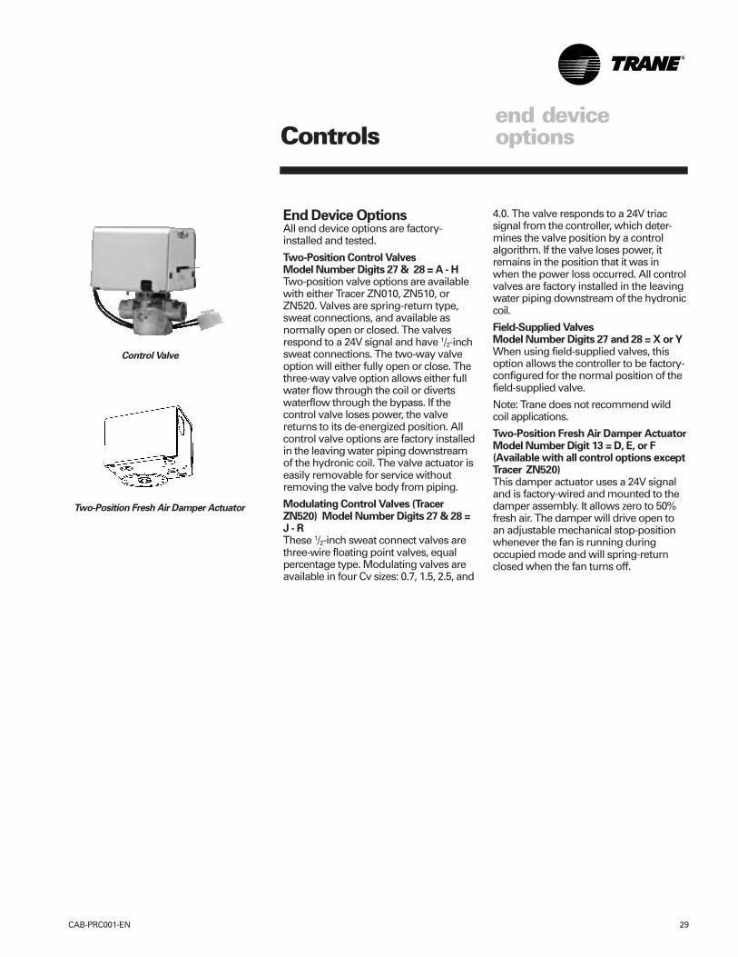
End Device OptionsAll end device options are factory-installed and tested.
Two-Position Control ValvesModel Number Digits 27 & 28 = A - HTwo-position valve options are availablewith either Tracer ZN010, ZN510, orZN520. Valves are spring-return type,sweat connections, and available asnormally open or closed. The valvesrespond to a 24V signal and have 1/2-inchsweat connections. The two-way valveoption will either fully open or close. Thethree-way valve option allows either fullwater flow through the coil or divertswaterflow through the bypass. If thecontrol valve loses power, the valvereturns to its de-energized position. Allcontrol valve options are factory installedin the leaving water piping downstreamof the hydronic coil. The valve actuator iseasily removable for service withoutremoving the valve body from piping.
Modulating Control Valves (TracerZN520) Model Number Digits 27 & 28 =J - RThese 1/2-inch sweat connect valves arethree-wire floating point valves, equalpercentage type. Modulating valves areavailable in four Cv sizes: 0.7, 1.5, 2.5, and
4.0. The valve responds to a 24V triacsignal from the controller, which deter-mines the valve position by a controlalgorithm. If the valve loses power, itremains in the position that it was inwhen the power loss occurred. All controlvalves are factory installed in the leavingwater piping downstream of the hydroniccoil.
Field-Supplied ValvesModel Number Digits 27 and 28 = X or YWhen using field-supplied valves, thisoption allows the controller to be factory-configured for the normal position of thefield-supplied valve.
Note: Trane does not recommend wildcoil applications.
Two-Position Fresh Air Damper ActuatorModel Number Digit 13 = D, E, or F(Available with all control options exceptTracer ZN520)This damper actuator uses a 24V signaland is factory-wired and mounted to thedamper assembly. It allows zero to 50%fresh air. The damper will drive open toan adjustable mechanical stop-positionwhenever the fan is running duringoccupied mode and will spring-returnclosed when the fan turns off.
Control Valve
Two-Position Fresh Air Damper Actuator
Electrical Data
30 CAB-PRC001-EN
Minimum Circuit Ampacity(MCA) and Maximum FuseSize (MFS) Calculations
Units with Electric HeatHACR (heating, air conditioning, andrefrigeration) type circuit breakers arerequired in the branch circuit wiring for allunits with electric heat. To compute MCAand MFS, see Tables ED-2 through ED-5on page 31 for motor FLAs and TablesED-6 through ED-8 on pages 32-33 forelectric heat amps.
Calculating electric heat amps:Single stage, three phase =heat kW * 1000/1.732/volts
Two stage, three phase =total heat kW * 1000/1.732/volts
Note: Use 240V heat voltage for 230Vunits.
Calculating MCA:MCA = 1.25 * (heat amps + sum of allmotor FLAs)
Calculating MFS:MFS = (2.25 * largest motor FLA) +second motor FLA, size 10-12 units only +heat amps
Use the closest larger fuse or HACRcircuit breaker above the MCA. Standardfuse sizes are: 15, 20, 25, 30, 35, 40, 45,50, 60 amps.
Electric heat MBH = heater kW * 3.413
Units Without Electric HeatTo compute MCA and MFS, see TablesED-2 through ED-5 on page 31 for motorFLAs and Tables ED-6 through ED-8 onpages 32-33 for electric heat amps.
Calculating MCA:MCA = (1.25) x largest motor FLA +second motor FLA, unit sizes 10-12 only
Calculating MFS:MFS or HACR1 type circuit breaker = 15amps for all units without electric heat.
1 HACR (heating, air-conditioning andrefrigeration) type circuit breakers arerequired in the branch circuit wiring forall size 10 and 12 units.
Table ED-1. Decimal to fractional hp (kW)
conversion
unit size decimal fraction02 .03 1/30
.07 1/15
03 .04 1/25
.05 1/20
.08 1/12
04 .05 1/20
.06 1/16
.10 1/10
.13 1/8
06 .07 1/15
.12 1/8
.16 1/6
.24 1/4
08 .12 1/8
.13 1/8
.24 1/4
10 .05 .07 1/201/15
.06 .12 1/161/8
.10 .16 1/101/6
.13 .24 1/81/4
12 .05 .12 1/201/8
.06 .13 1/161/8
.10 .24 1/101/4
.13 .24 1/81/4
Note:Values for fractional HPs (kWs) are approximate values andnot necessarily the actual HP (kW). Size 10 & 12 units havetwo motors.
Electrical Data
CAB-PRC001-EN 31
Table ED-2. Free discharge motors on units with two-row, electric, or steam coils
unit 115 volt 208-230 volt 277-480 volt rpmsize FLA hp (kW) FLA hp (kW) FLA hp (kW) H M L02 0.6 .03 (.02) 0.3 .03 (.02) 0.2 .03 (.02) 980 840 65503 0.7 .04 (.02) 0.4 .04 (.02) 0.3 .04 (.02) 980 780 58004 0.9 .05 (.04) 0.5 .05 (.04) 0.4 .05 (.04) 1050 780 58006 1.2 .07 (.05) 0.6 .07 (.05) 0.5 .07 (.05) 1030 780 58008 1.4 .12 (.09) 0.9 .12 (.09) 0.6 .12 (.09) 1080 800 60010 0.9 .05 (.04) 0.5 .05 (.04) 0.4 .05 (.04) 1050 780 580
1.2 .07 (.05) 0.6 .07 (.05) 0.5 .07 (.05) 1030 780 58012 0.9 .05 (.04) 0.5 .05 (.04) 0.4 .05 (.04) 1050 780 580
1.4 .12 (.09) 0.9 .12 (.09) 0.6 .12 (.09) 108 800 600
Table ED-3. High static motors on units with two-row, electric, or steam coils
unit 115 volt 208-230 volt 277- 480 volt rpmsize FLA hp (kW) FLA hp (kW) FLA hp (kW) H M L02 1.1 .07 (.05) 0.6 .07 (.05) 0.5 .07 (.05) 1480 1110 86503 1.4 .08 (.06) 0.7 .08 (.06) 0.6 .08 (.06) 1400 1175 86004 1.6 .10 (.07) 0.8 .10 (.07) 0.7 .10 (.07) 1475 1315 107006 2.6 .16 (.12) 1.2 .16 (.12) 1.0 .16 (.12) 1400 1070 85508 3.4 .24 (.18) 1.4 .24 (.18) 1.1 .24 (.18) 1475 1285 97510 1.6 .10 (.07) 0.8 .10 (.07) 0.7 .10 (.07) 1475 1315 1070
2.6 .16 (.12) 1.2 .16 (.12) 1.0 .16 (.12) 1400 1070 85512 1.6 .10 (.07) 0.5 .10 (.07) 0.7 .10 (.12) 1475 1315 1240
3.4 .24 (.18) 0.9 .24 (.18) 1.1 .24 (.18) 1475 1285 975
Table ED-4. Free discharge motors on units with three and four-row coils
unit 115 volt 208-230 volt 277-480 volt rpmsize FLA hp(kW) FLA hpP (kW) FLA hp (kW) H M L02 0.6 .03 (.02) 0.3 .03 (.02) 0.2 .03 (.02) 980 840 65503 0.8 .05 (.04) 0.5 .05 (.04) 0.4 .05 (.04) 1080 800 60004 1.0 .06 (.04) 0.6 .06 (.04) 0.5 .06 (.04) 1080 800 60006 1.4 .12 (.09) 0.9 .12 (.09) 0.6 .12 (.09) 1080 800 60008 1.7 .13 (.10) 1.0 .13 (.10) 0.8 .13 (.10) 1080 800 60010 1.0 .06 (.04) 0.6 .06 (.04) 0.5 .06 (.04) 1080 800 600
1.4 .12 (.09) 0.9 .12 (.09) 0.6 .12 (.09) 1080 800 60012 1.0 .06 (.04) 0.6 .06 (.04) 0.5 .06 (.04) 1080 800 600
1.7 .13 (.10) 1.0 .13 (.10) 0.8 .13 (.10) 1080 800 600
Table ED-5. High static motors on units with three and four-row coils
unit 115 volt 208-230 volt 277-480 volt rpmsize FLA hp (kW) FLA hp (kW) FLA hp (kW) H M L02 1.1 .07 (.05) 0.6 .07 (.05) 0.5 .07 (.05) 1480 1110 86503 1.3 .08 (.06) 0.7 .08 (.06) 0.5 .08 (.06) 1500 1355 111004 2.1 .13 (.10) 0.9 .13 (.10) 0.7 .13 (.10) 1580 1375 124006 3.4 .24 (.18) 1.4 .24 (.18) 1.1 .24 (.18) 1475 1285 97508 3.4 .24 (.18) 1.4 .24 (.18) 1.1 .24 (.18) 1475 1285 97510 2.1 .13 (.10) 0.9 .13 (.10) 0.7 .13 (.10) 1580 1375 1240
3.4 .24 (.18) 1.4 .24 (.18) 1.1 .24 (.18) 1475 1285 97512 2.1 .13 (.10) 0.9 .13 (.10) 0.7 .13 (.10 ) 1580 1375 1240
3.4 .24 (.18) 1.4 .24 (.18) 1.1 .24 (.18) 1475 1285 975
Note: Actual rpm will vary with application and configuration. Size 10 & 12 units have two motors.
Electrical Data
32 CAB-PRC001-EN
Table ED-6. Two-stage electric heat (digit 18 = U)
unit 1st stage total totalsize volts hz phase wires kW kW amps/ph
208 1 2 0.75 2.25 10.9240 1 2 1.0 3.0 12.5
02 277 60 1 2 1.0 3.0 10.9208 3 3 0.75 2.25 6.3240 3 3 1.0 3.0 7.3480 3 4 1.0 3.0 3.7208 1 2 1.5 4.5 21.7240 1 2 2.0 6.0 25.0
03 277 60 1 2 2.0 6.0 21.7208 3 3 1.5 4.5 12.6240 3 3 2.0 6.0 14.5480 3 4 2.0 6.0 7.3208 1 2 1.9 5.7 27.5240 1 2 2.5 7.5 31.3
04 277 60 1 2 2.5 7.5 27.1208 3 3 1.9 5.7 15.9240 3 3 2.5 7.5 18.1480 3 4 2.5 7.5 9.1208 1 2 3.4 7.9 38.0240 1 2 4.5 10.5 43.8
06 277 60 1 2 4.5 10.5 38.0208 3 3 3.4 7.9 21.9240 3 3 4.5 10.5 25.3480 3 4 4.5 10.5 12.7208 1 2 4.5 10.1 48.8240 1 2 6.0 13.5 56.3
08 277 60 1 2 6.0 13.5 48.8208 3 3 4.5 10.1 28.2240 3 3 6.0 13.5 32.5480 3 4 6.0 13.5 16.3208 1 2 6.0 13.5 65.0240 1 2 8.0 18.0 75.0
10 277 60 1 2 8.0 18.0 65.0208 3 3 6.0 13.5 37.6240 3 3 8.0 18.0 43.3480 3 4 8.0 18.0 21.7208 1 2 6.8 15.0 72.3240 1 2 9.0 20.0 83.4
12 277 60 1 2 9.0 20.0 72.3208 3 3 6.8 15.0 41.7240 3 3 9.0 20.0 48.2480 3 4 9.0 20.0 24.1
Note: When both stages are on, the electric heat will operate only when fan is in high speed. All data based onindividual units.
Electrical Data
CAB-PRC001-EN 33
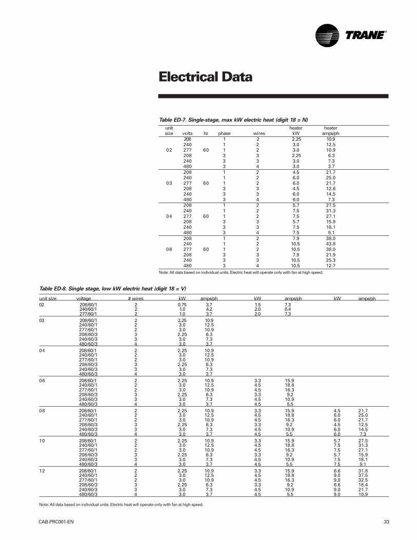
Table ED-8. Single stage, low kW electric heat (digit 18 = V)
unit size voltage # wires kW amps/ph kW amps/ph kW amps/ph02 208/60/1 2 0.75 3.7 1.5 7.3
240/60/1 2 1.0 4.2 2.0 8.4277/60/1 2 1.0 3.7 2.0 7.3
03 208/60/1 2 2.25 10.9240/60/1 2 3.0 12.5277/60/1 2 3.0 10.9208/60/3 3 2.25 6.3240/60/3 3 3.0 7.3480/60/3 4 3.0 3.7
04 208/60/1 2 2.25 10.9240/60/1 2 3.0 12.5277/60/1 2 3.0 10.9208/60/3 3 2.25 6.3240/60/3 3 3.0 7.3480/60/3 4 3.0 3.7
06 208/60/1 2 2.25 10.9 3.3 15.9240/60/1 2 3.0 12.5 4.5 18.8277/60/1 2 3.0 10.9 4.5 16.3208/60/3 3 2.25 6.3 3.3 9.2240/60/3 3 3.0 7.3 4.5 10.9480/60/3 4 3.0 3.7 4.5 5.5
08 208/60/1 2 2.25 10.9 3.3 15.9 4.5 21.7240/60/1 2 3.0 12.5 4.5 18.8 6.0 25.0277/60/1 2 3.0 10.9 4.5 16.3 6.0 21.7208/60/3 3 2.25 6.3 3.3 9.2 4.5 12.5240/60/3 3 3.0 7.3 4.5 10.9 6.0 14.5480/60/3 4 3.0 3.7 4.5 5.5 6.0 7.3
10 208/60/1 2 2.25 10.9 3.3 15.9 5.7 27.5240/60/1 2 3.0 12.5 4.5 18.8 7.5 31.3277/60/1 2 3.0 10.9 4.5 16.3 7.5 27.1208/60/3 3 2.25 6.3 3.3 9.2 5.7 15.9240/60/3 3 3.0 7.3 4.5 10.9 7.5 18.1480/60/3 4 3.0 3.7 4.5 5.5 7.5 9.1
12 208/60/1 2 2.25 10.9 3.3 15.9 6.6 31.8240/60/1 2 3.0 12.5 4.5 18.8 9.0 37.5277/60/1 2 3.0 10.9 4.5 16.3 9.0 32.5208/60/3 3 2.25 6.3 3.3 9.2 6.6 18.4240/60/3 3 3.0 7.3 4.5 10.9 9.0 21.7480/60/3 4 3.0 3.7 4.5 5.5 9.0 10.9
Note: All data based on individual units. Electric heat will operate only with fan at high speed.
Table ED-7. Single-stage, max kW electric heat (digit 18 = N)
unit heater heatersize volts hz phase wires kW amps/ph
208 1 2 2.25 10.9240 1 2 3.0 12.5
02 277 60 1 2 3.0 10.9208 3 3 2.25 6.3 240 3 3 3.0 7.3480 3 4 3.0 3.7208 1 2 4.5 21.7240 1 2 6.0 25.0
03 277 60 1 2 6.0 21.7208 3 3 4.5 12.6240 3 3 6.0 14.5480 3 4 6.0 7.3208 1 2 5.7 27.5240 1 2 7.5 31.3
04 277 60 1 2 7.5 27.1208 3 3 5.7 15.9240 3 3 7.5 18.1480 3 4 7.5 9.1208 1 2 7.9 38.0240 1 2 10.5 43.8
06 277 60 1 2 10.5 38.0208 3 3 7.9 21.9240 3 3 10.5 25.3480 3 4 10.5 12.7
Note: All data based on individual units. Electric heat will operate only with fan at high speed.
Dimensionsand Weights
CAB-PRC001-EN34
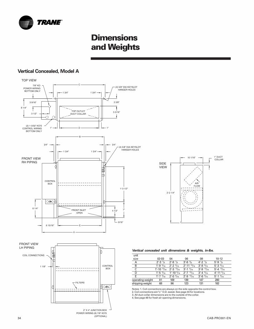
Vertical Concealed, Model A
Vertical concealed unit dimensions & weights, in-lbs.
unitsize 02-03 04 06 08 10-12A 2’-3 7/8 2’-8 7/8 3’-6 3/8 4’-2 7/8 5’-9 7/8B 1’-9 5/16 2’-2 5/16 2’-11 13/16 3’-8 5/16 5’-3 5/16
C 1’-10 13/16 2’-3 13/16 3’-1 5/16 3’-9 13/16 5’-4 13/16
D 1’-5 5/16 1’-10 5/16 2’-7 13/16 3’-4 5/16 4’-11 5/16
E 1’-7 5/16 2’-0 5/16 2’-9 13/16 3’-6 5/16 5’-1 5/16
operating weight 81 109 139 147 200shipping weight 68 96 123 131 182
Notes: 1. Coil connections are always on the side opposite the control box.2. Coil connections are 5/8” O.D. sweat. See page 44 for locations.3. All duct collar dimensions are to the outside of the collar.4. See page 46 for fresh air opening dimensions.
Dimensionsand Weights
CAB-PRC001-EN 35
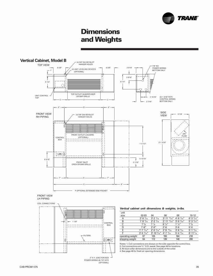
Vertical cabinet unit dimensions & weights, in-lbs.
unitsize 02-03 04 06 08 10-12A 2’-9 5/16 3’-2 5/16 3’-11 13/16” 4’-8 5/16” 6’-3 5/16”B 1’-9 5/16 2’-2 5/16 2’-11 13/16” 3’-8 5/16” 5’-3 5/16”C 7 5/8 7 1/8 8 7/8” 7 1/8” 7 5/8D 1’-6” 2’-0” 2’-6 3’-6 5’-0E 1’-7 5/16” 2’-0 5/16” 2’-9 13/16 3’-6 5/16 5’-1 5/16
F 3’-5 5/16” 3’-10 5/16” 4’-7 3/16 5’-4 5/16 6’-11 516
operating weight 97 125 155 164 218shipping weight 84 112 139 148 200
Notes: 1. Coil connections are always on the side opposite the control box.2. Coil connections are 5/8” O.D. sweat. See page 44 for locations.3. All duct collar dimensions are to the outside of the collar.4. See page 46 for fresh air opening dimensions.
Vertical Cabinet, Model B
Dimensionsand Weights
CAB-PRC001-EN36
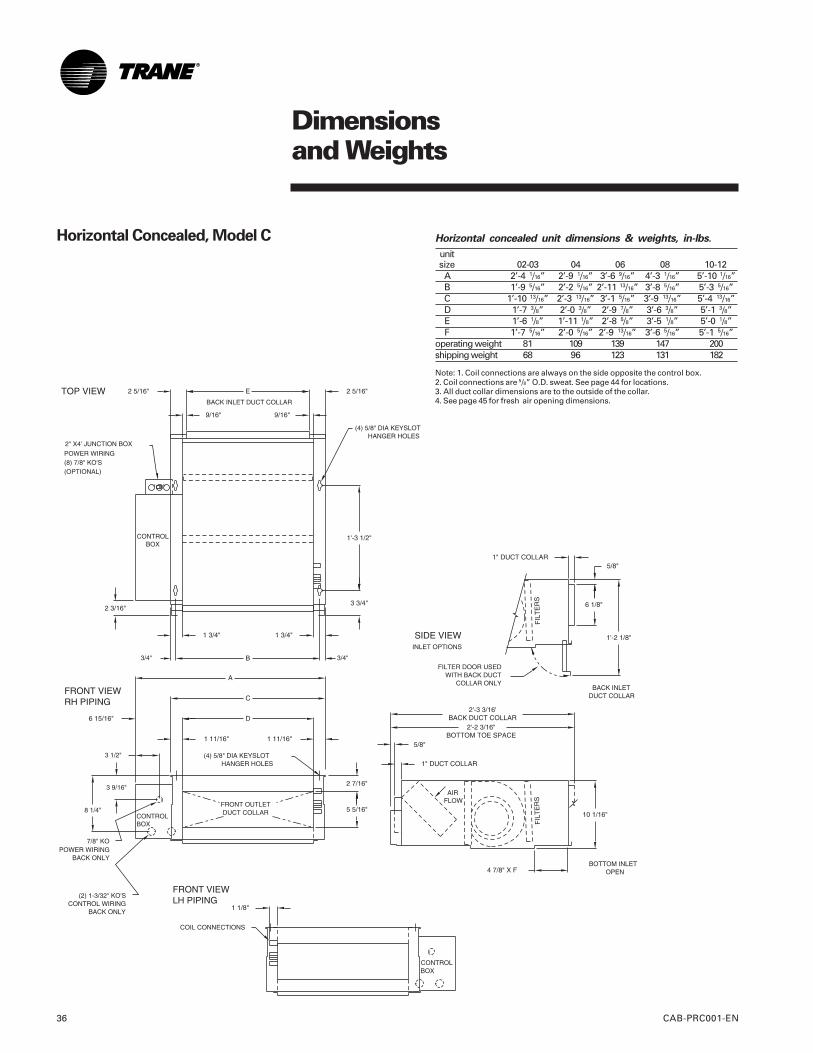
Horizontal Concealed, Model C Horizontal concealed unit dimensions & weights, in-lbs.
unitsize 02-03 04 06 08 10-12A 2’-4 1/16” 2’-9 1/16” 3’-6 9/16” 4’-3 1/16” 5’-10 1/16”B 1’-9 5/16” 2’-2 5/16” 2’-11 13/16” 3’-8 5/16” 5’-3 5/16”C 1’-10 13/16” 2’-3 13/16” 3’-1 5/16” 3’-9 13/16” 5’-4 13/16”D 1’-7 3/8” 2’-0 3/8” 2’-9 7/8” 3’-6 3/8” 5’-1 3/8”E 1’-6 1/8” 1’-11 1/8” 2’-8 5/8” 3’-5 1/8” 5’-0 1/8”F 1’-7 5/16” 2’-0 5/16” 2’-9 13/16” 3’-6 5/16” 5’-1 5/16”
operating weight 81 109 139 147 200shipping weight 68 96 123 131 182
Note: 1. Coil connections are always on the side opposite the control box.2. Coil connections are 5/8” O.D. sweat. See page 44 for locations.3. All duct collar dimensions are to the outside of the collar.4. See page 45 for fresh air opening dimensions.
Dimensionsand Weights
CAB-PRC001-EN 37
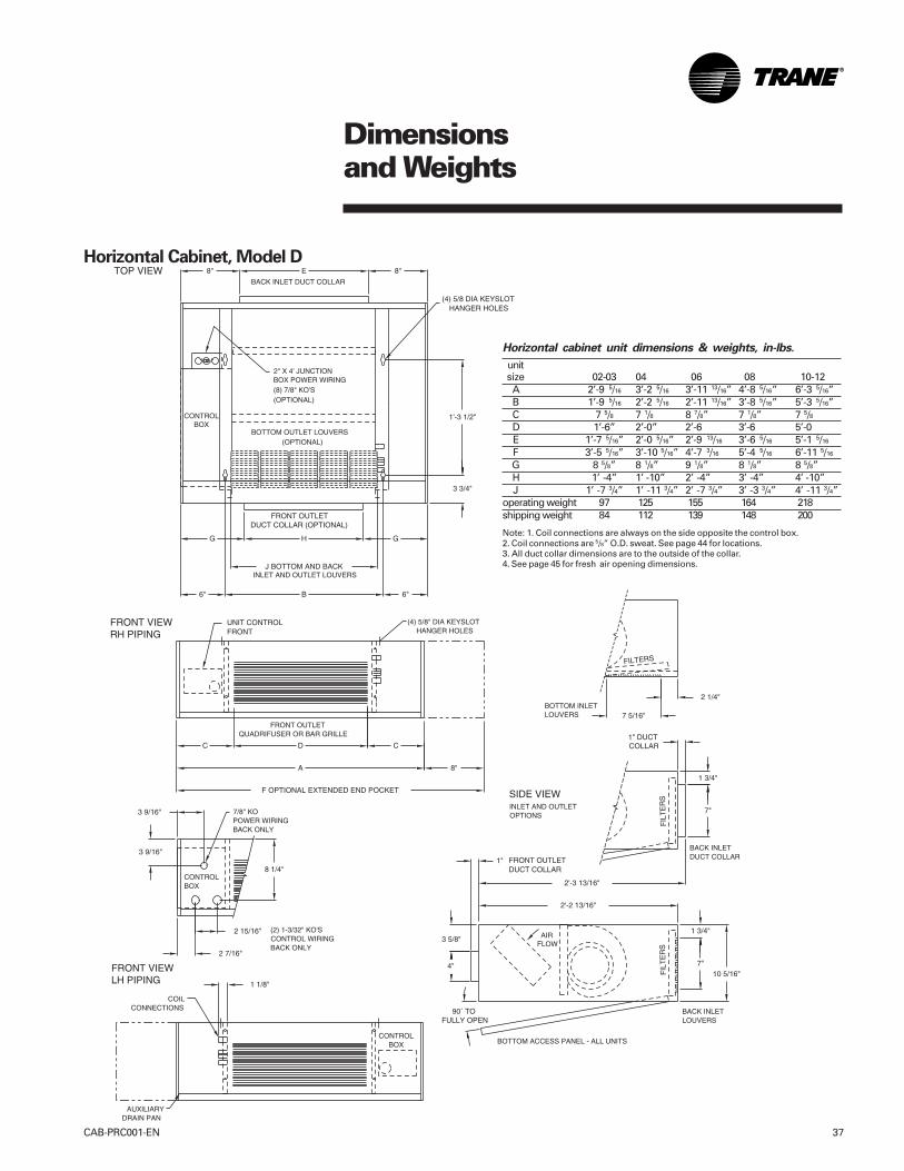
Horizontal Cabinet, Model D
Horizontal cabinet unit dimensions & weights, in-lbs.
unitsize 02-03 04 06 08 10-12A 2’-9 5/16 3’-2 5/16 3’-11 13/16” 4’-8 5/16” 6’-3 5/16”B 1’-9 5/16 2’-2 5/16 2’-11 13/16” 3’-8 5/16” 5’-3 5/16”C 7 5/8 7 1/8 8 7/8” 7 1/8” 7 5/8D 1’-6” 2’-0” 2’-6 3’-6 5’-0E 1’-7 5/16” 2’-0 5/16” 2’-9 13/16 3’-6 5/16 5’-1 5/16
F 3’-5 5/16” 3’-10 5/16” 4’-7 3/16 5’-4 5/16 6’-11 5/16
G 8 5/8” 8 1/8” 9 1/8” 8 1/8” 8 5/8”H 1’ -4” 1’ -10” 2’ -4” 3’ -4” 4’ -10”J 1’ -7 3/4” 1’ -11 3/4” 2’ -7 3/4” 3’ -3 3/4” 4’ -11 3/4”
operating weight 97 125 155 164 218shipping weight 84 112 139 148 200
Note: 1. Coil connections are always on the side opposite the control box.2. Coil connections are 5/8” O.D. sweat. See page 44 for locations.3. All duct collar dimensions are to the outside of the collar.4. See page 45 for fresh air opening dimensions.
Dimensionsand Weights
CAB-PRC001-EN38
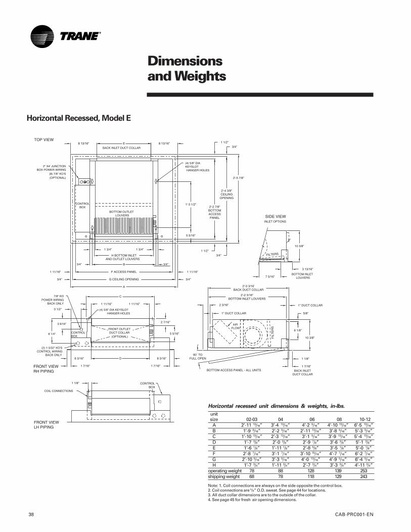
Horizontal Recessed, Model E
Horizontal recessed unit dimensions & weights, in-lbs.
unitsize 02-03 04 06 08 10-12A 2’-11 13/16” 3’-4 13/16” 4’-2 5/16” 4’-10 13/16” 6’-5 13/16”B 1’-9 5/16” 2’-2 5/16” 2’-11 13/16” 3’-8 5/16” 5’-3 5/16”C 1’-10 13/16” 2’-3 13/16” 3’-1 5/16” 3’-9 13/16” 5’-4 13/16”D 1’-7 3/8” 2’-0 3/8” 2’-9 7/8” 3’-6 3/8” 5’-1 3/8”E 1’-6 1/8” 1’-11 1/8” 2’-8 5/8” 3’-5 1/8” 5’-0 1/8”F 2’-8 7/16” 3’-1 7/16” 3’-10 15/16” 4’-7 7/16” 6’-2 7/16”G 2’-10 5/16” 3’-3 5/16” 4’-0 13/16” 4’-9 5/16” 6’-4 5/16”H 1’-7 3/4” 1’-11 3/4” 2’-7 3/4” 3’-3 3/4” 4’-11 3/4”
operating weight 78 88 128 139 253shipping weight 68 78 118 129 243
Note: 1. Coil connections are always on the side opposite the control box.2. Coil connections are 5/8” O.D. sweat. See page 44 for locations.3. All duct collar dimensions are to the outside of the collar.4. See page 45 for fresh air opening dimensions.
Dimensionsand Weights
CAB-PRC001-EN 39
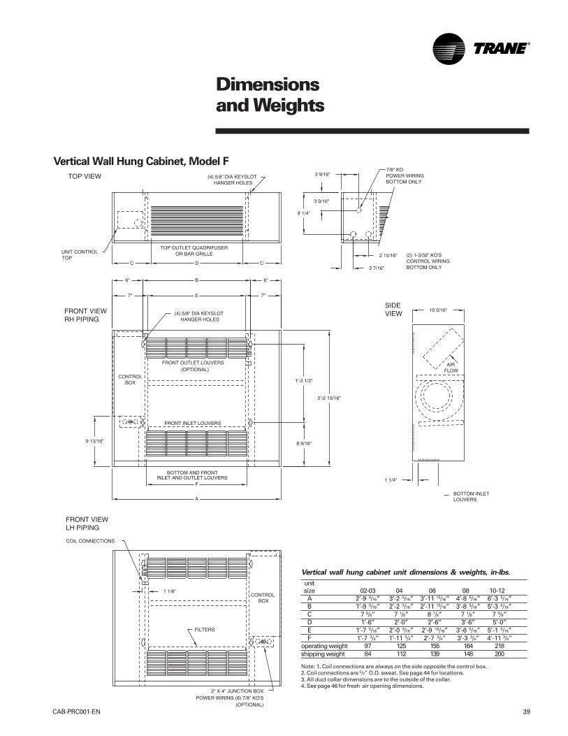
Vertical wall hung cabinet unit dimensions & weights, in-lbs.
unitsize 02-03 04 06 08 10-12A 2’-9 5/16” 3’-2 5/16” 3’-11 13/16” 4’-8 5/16” 6’-3 5/16”B 1’-9 5/16” 2’-2 5/16” 2’-11 13/16” 3’-8 5/16” 5’-3 5/16”C 7 5/8” 7 1/8” 8 7/8” 7 1/8” 7 5/8”D 1’-6” 2’-0” 2’-6” 3’-6” 5’-0”E 1’-7 5/16” 2’-0 5/16” 2’-9 13/16” 3’-6 5/16” 5’-1 5/16”F 1’-7 3/4” 1’-11 3/4” 2’-7 3/4” 3’-3 3/4” 4’-11 3/4”
operating weight 97 125 155 164 218shipping weight 84 112 139 148 200
Note: 1. Coil connections are always on the side opposite the control box.2. Coil connections are 5/8” O.D. sweat. See page 44 for locations.3. All duct collar dimensions are to the outside of the collar.4. See page 46 for fresh air opening dimensions.
Vertical Wall Hung Cabinet, Model F
Dimensionsand Weights
CAB-PRC001-EN40
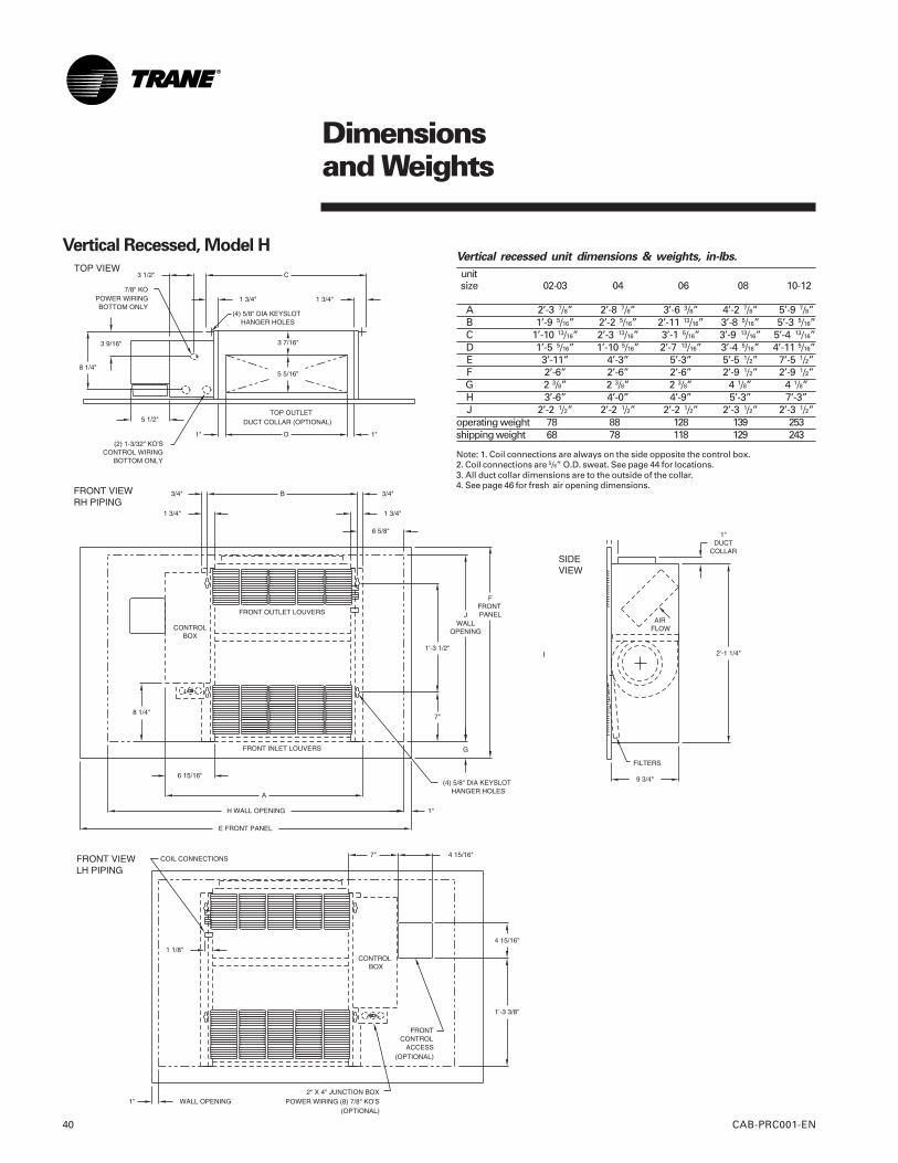
Vertical Recessed, Model HVertical recessed unit dimensions & weights, in-lbs.
unitsize 02-03 04 06 08 10-12
A 2’-3 7/8” 2’-8 7/8” 3’-6 3/8” 4’-2 7/8” 5’-9 7/8”B 1’-9 5/16” 2’-2 5/16” 2’-11 13/16” 3’-8 5/16” 5’-3 5/16”C 1’-10 13/16” 2’-3 13/16” 3’-1 5/16” 3’-9 13/16” 5’-4 13/16”D 1’-5 5/16” 1’-10 5/16” 2’-7 13/16” 3’-4 5/16” 4’-11 5/16”E 3’-11” 4’-3” 5’-3” 5’-5 1/2” 7’-5 1/2”F 2’-6” 2’-6” 2’-6” 2’-9 1/2” 2’-9 1/2”G 2 3/8” 2 3/8” 2 3/8” 4 1/8” 4 1/8”H 3’-6” 4’-0” 4’-9” 5’-3” 7’-3”J 2’-2 1/2” 2’-2 1/2” 2’-2 1/2” 2’-3 1/2” 2’-3 1/2”
operating weight 78 88 128 139 253shipping weight 68 78 118 129 243
Note: 1. Coil connections are always on the side opposite the control box.2. Coil connections are 5/8” O.D. sweat. See page 44 for locations.3. All duct collar dimensions are to the outside of the collar.4. See page 46 for fresh air opening dimensions.
Dimensionsand Weights
CAB-PRC001-EN 41
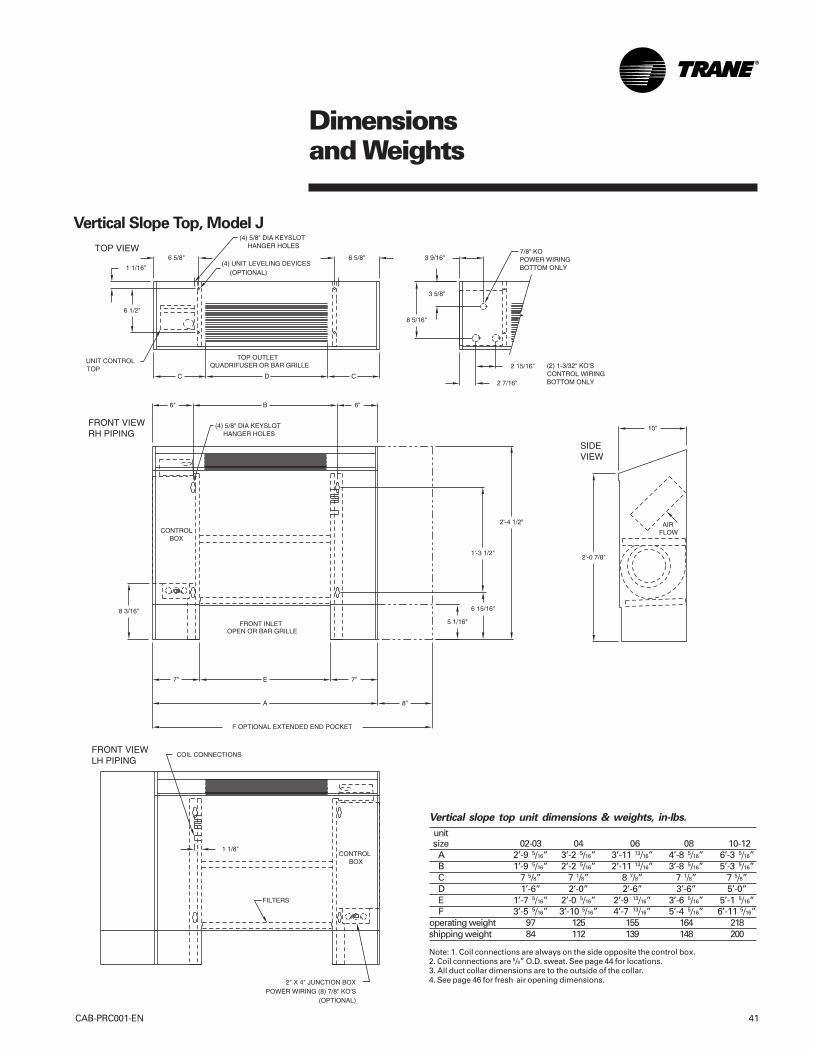
Vertical Slope Top, Model J
Vertical slope top unit dimensions & weights, in-lbs.
unitsize 02-03 04 06 08 10-12A 2’-9 5/16” 3’-2 5/16” 3’-11 13/16” 4’-8 5/16” 6’-3 5/16”B 1’-9 5/16” 2’-2 5/16” 2’-11 13/16” 3’-8 5/16” 5’-3 5/16”C 7 5/8” 7 1/8” 8 7/8” 7 1/8” 7 5/8”D 1’-6” 2’-0” 2’-6” 3’-6” 5’-0”E 1’-7 5/16” 2’-0 5/16” 2’-9 13/16” 3’-6 5/16” 5’-1 5/16”F 3’-5 5/16” 3’-10 5/16” 4’-7 13/16” 5’-4 5/16” 6’-11 5/16”
operating weight 97 125 155 164 218shipping weight 84 112 139 148 200
Note: 1. Coil connections are always on the side opposite the control box.2. Coil connections are 5/8” O.D. sweat. See page 44 for locations.3. All duct collar dimensions are to the outside of the collar.4. See page 46 for fresh air opening dimensions.
Dimensionsand Weights
CAB-PRC001-EN42
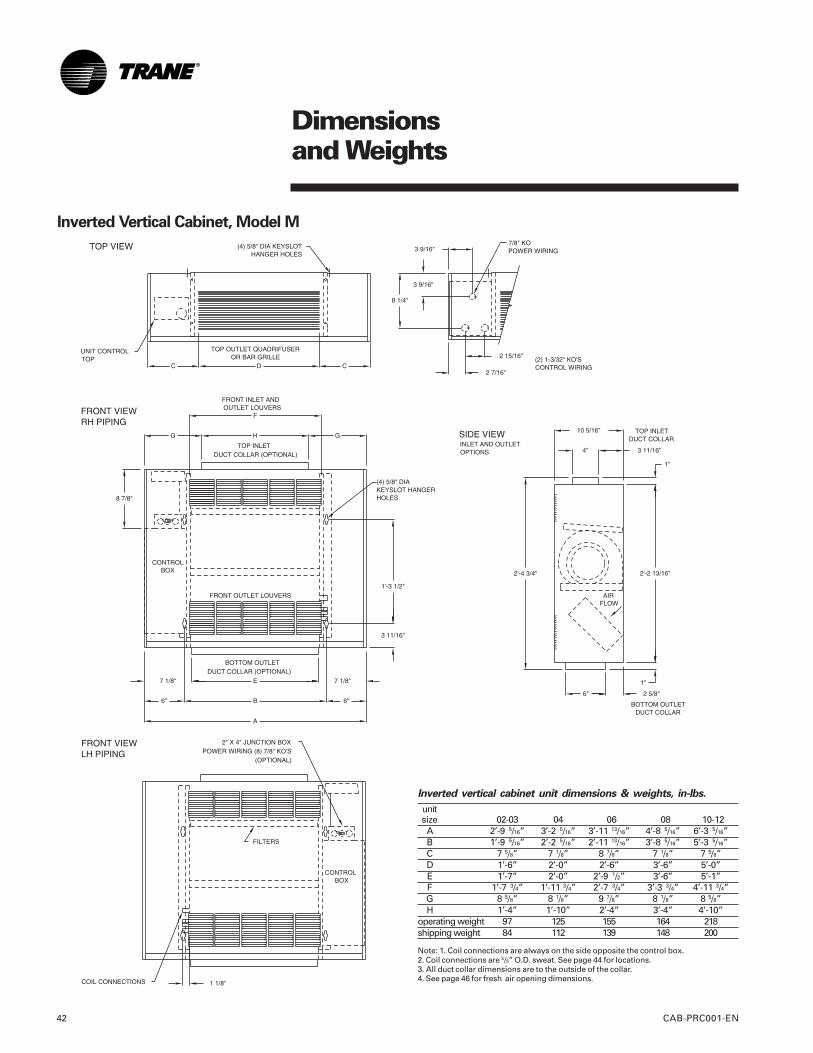
Inverted Vertical Cabinet, Model M
Inverted vertical cabinet unit dimensions & weights, in-lbs.
unitsize 02-03 04 06 08 10-12A 2’-9 5/16” 3’-2 5/16” 3’-11 13/16” 4’-8 5/16” 6’-3 5/16”B 1’-9 5/16” 2’-2 5/16” 2’-11 13/16” 3’-8 5/16” 5’-3 5/16”C 7 5/8” 7 1/8” 8 7/8” 7 1/8” 7 5/8”D 1’-6” 2’-0” 2’-6” 3’-6” 5’-0”E 1’-7” 2’-0” 2’-9 1/2” 3’-6” 5’-1”F 1’-7 3/4” 1’-11 3/4” 2’-7 3/4” 3’-3 3/4” 4’-11 3/4”G 8 5/8” 8 1/8” 9 7/8” 8 1/8” 8 5/8”H 1’-4” 1’-10” 2’-4” 3’-4” 4’-10”
operating weight 97 125 155 164 218shipping weight 84 112 139 148 200
Note: 1. Coil connections are always on the side opposite the control box.2. Coil connections are 5/8” O.D. sweat. See page 44 for locations.3. All duct collar dimensions are to the outside of the collar.4. See page 46 for fresh air opening dimensions.
Dimensionsand Weights
CAB-PRC001-EN 43
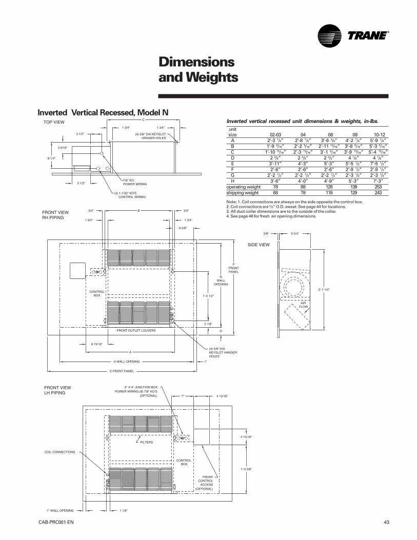
Inverted Vertical Recessed, Model NInverted vertical recessed unit dimensions & weights, in-lbs.
unitsize 02-03 04 06 08 10-12A 2’-3 7/8” 2’-8 7/8” 3’-6 3/8” 4’-2 7/8” 5’-9 7/8”B 1’-9 5/16” 2’-2 5/16” 2’-11 13/16” 3’-8 5/16” 5’-3 5/16”C 1’-10 13/16” 2’-3 13/16” 3’-1 5/16” 3’-9 13/16” 5’-4 13/16”D 2 3/8” 2 3/8” 2 3/8” 4 1/8” 4 1/8”E 3’-11” 4’-3” 5’-3” 5’-5 1/2” 7’-5 1/2”F 2’-6” 2’-6” 2’-6” 2’-9 1/2” 2’-9 1/2”G 2’-2 1/2” 2’-2 1/2” 2’-2 1/2” 2’-3 1/2” 2’-3 1/2”H 3’-6” 4’-0” 4’-9” 5’-3” 7’-3”
operating weight 78 88 128 139 253shipping weight 68 78 118 129 243
Note: 1. Coil connections are always on the side opposite the control box.2. Coil connections are 5/8” O.D. sweat. See page 44 for locations.3. All duct collar dimensions are to the outside of the collar.4. See page 46 for fresh air opening dimensions.
Dimensionsand Weights
CAB-PRC001-EN44
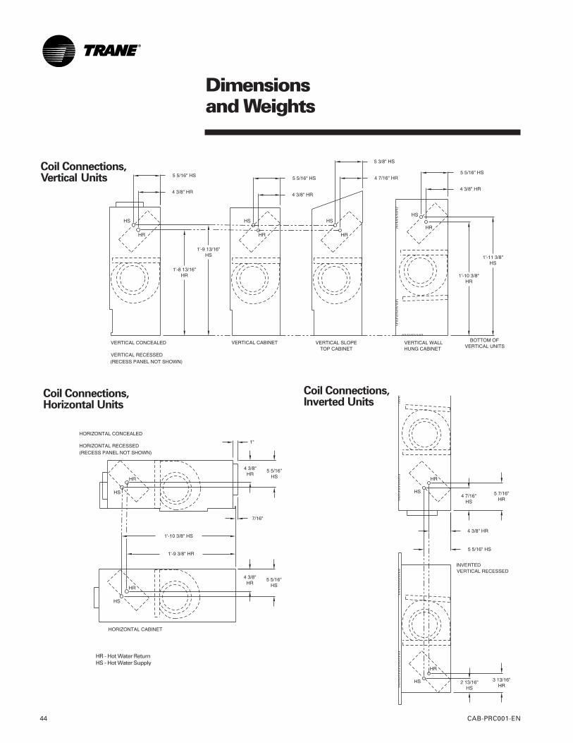
Coil Connections,Vertical Units
Coil Connections,Horizontal Units
HR - Hot Water ReturnHS - Hot Water Supply
Coil Connections,Inverted Units
Dimensionsand Weights
CAB-PRC001-EN 45
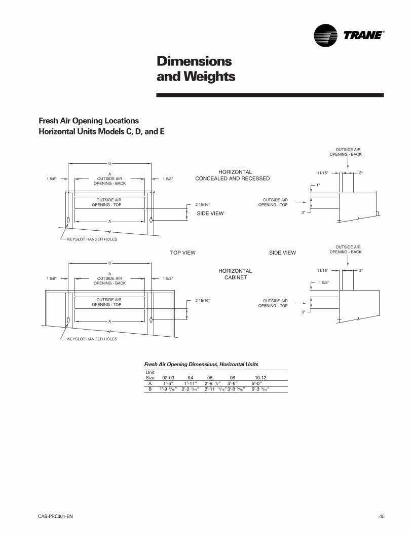
Fresh Air Opening Locations
Horizontal Units Models C, D, and E
Fresh Air Opening Dimensions, Horizontal Units
UnitSize 02-03 04 06 08 10-12
A 1’-6” 1’-11” 2’-8 1/2” 3’-5” 5’-0”B 1’-9 5/16” 2’-2 5/16” 2’-11 13/16”3’-8 5/16” 5’-3 5/16”
Dimensionsand Weights
CAB-PRC001-EN46
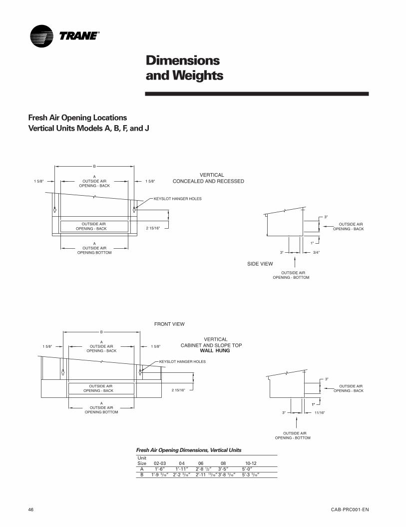
Fresh Air Opening Locations
Vertical Units Models A, B, F, and J
Fresh Air Opening Dimensions, Vertical Units
UnitSize 02-03 04 06 08 10-12
A 1’-6” 1’-11” 2’-8 1/2” 3’-5” 5’-0”B 1’-9 5/16” 2’-2 5/16” 2’-11 13/16”3’-8 5/16” 5’-3 5/16”
WALL HUNG
Dimensionsand Weights
CAB-PRC001-EN 47
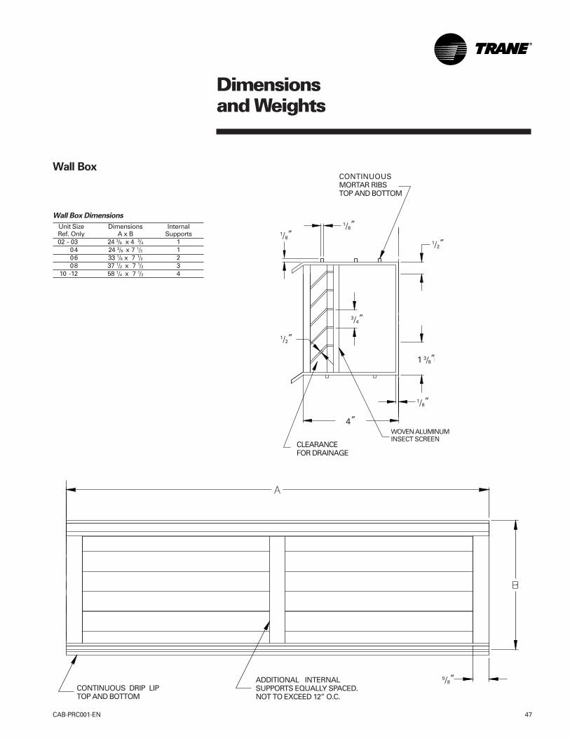
Wall Box Dimensions
Unit Size Dimensions InternalRef. Only A x B Supports02 - 03 24 3/8 x 4 3/4 1
04 24 3/8 x 7 1/2 106 33 1/8 x 7 1/2 208 37 1/2 x 7 1/2 3
10 -12 58 1/4 x 7 1/2 4
CLEARANCEFOR DRAINAGE
CONTINUOUSMORTAR RIBSTOP AND BOTTOM
WOVEN ALUMINUMINSECT SCREEN
1/8”1/8”
1/2”
1/8”
1/2”
3/4”
1 3/8”
4”
CONTINUOUS DRIP LIPTOP AND BOTTOM
ADDITIONAL INTERNALSUPPORTS EQUALLY SPACED.NOT TO EXCEED 12” O.C.
5/8”
Wall Box
Dimensionsand Weights
CAB-PRC001-EN48
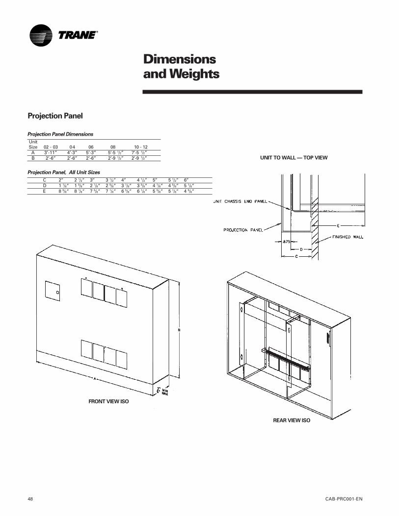
Projection Panel, All Unit Sizes
C 2” 2 1/2” 3” 3 1/2” 4” 4 1/2” 5” 5 1/2” 6”D 1 1/8“ 1 5/8“ 2 1/8“ 2 5/8“ 3 1/8“ 3 5/8“ 4 1/8“ 4 5/8“ 5 1/8“E 8 5/8“ 8 1/8“ 7 5/8“ 7 1/8“ 6 5/8“ 6 1/8“ 5 5/8“ 5 1/8“ 4 5/8“
Projection Panel Dimensions
UnitSize 02 - 03 04 06 08 10 - 12A 3’-11” 4’-3” 5’-3” 5’-5 1/2” 7’-5 1/2”B 2’-6” 2’-6” 2’-6” 2’-9 1/2” 2’-9 1/2”
FRONT VIEW ISO
REAR VIEW ISO
Projection Panel
UNIT TO WALL — TOP VIEW
MechanicalSpecifications
CAB-PRC001-EN 49
Force-Flo™ Cabinet HeaterMechanical Specifications
Performance DataCapacity: Unit capacities are in accor-dance with Industry Room Fan-Coil AirConditioner Certification Program underARI Standard 440-97. Safety: All standardunits are UL listed in the United Statesand Canada. Units comply with NFPA90Arequirements.
Construction
All UnitsThe unit includes a chassis, coil, fanwheel(s), fan casing(s), fan board, andmotor(s). The fan board assembly iseasily removable. The fan board assem-bly includes a quick-disconnect motorplug. The chassis construction is 18-gagegalvanized steel, and continuous through-out the unit. The unit is acoustically andthermally insulated with closed-cellinsulation. All panels are made rigid bychannel forming.
Vertical Cabinet and Slope Top UnitsFront panel fabrication is 16-gagegalvanized steel. All other panels are 18-gage galvanized steel. Hinged accessdoor construction is 20-gage steel and isflush with top panel.
Vertical Wall Hung UnitFront panel fabrication is 16-gagegalvanized steel. All other panels are 18-gage galvanized steel. Side panels areremovable for piping access.
Horizontal Cabinet UnitsAll panels are 18-gage galvanized steel,including the bottom panel. The hingedaccess door is flush with front panel.Bottom panels ship with tamperproofscrew fasteners and safety chain.
Concealed/Recessed UnitsExposed panels on recessed units are 18-gage steel construction and ship separatefrom the unit. Bottom panels on horizontalrecessed models ship with tamperproofscrew fasteners and safety chain.
Unit FinishAll cabinet parts and exposed recessedpanels are cleaned, bonderized, phos-phatized, and painted with a bakedpowder finish available in six decoratorcolors. Standard finish meets ASTMB117 specifications (salt spray test).
FansThe aluminum fan wheels are centrifugalforward-curved and double-width. Fanwheels and housings are corrosionresistant. Fan housing construction isformed sheet metal.
MotorsAll permanent split capacitor motors arerun tested in assembled units. All motorshave integral thermal overload protectionwith a maximum ambient operatingtemperature of 104°F and are perma-nently lubricated. Motors are capable ofstarting at 78% of rated voltage andoperating at 90% of rated voltage on allspeed settings. Motors can operate up to10% over voltage.
Hot Water CoilsHot water coils are burst tested at 450psig (3,103 kPa) (air) and leak tested at100 psig (690 kPa) (air under water).Maximum main coil working pressure is300 psig (2,069 kPa). Maximum enteringwater temperature is 200°F (93°C). Tubesand u-bends are 3/8”(10 mm) OD copper.Fins are aluminum and are mechanicallybonded to the copper tubes. Coilstubouts are 5/8”(16 mm) OD coppertubing.
Steam CoilsThe steam heating coil is a one-row, tube-in-tube distributing type coil. Coil con-struction is aluminum fins mechanicallybonded with 1” (25 mm) OD coppertubing. Steam coils are (air) burst testedat 250 psig (1,724 kPa). Maximum steamcoil working pressure is 100 psig (689kPa). Maximum entering steam tempera-ture is 325°F (163°C). Tubes and u-bendsare 5/8” (16 mm) OD copper. Fins arealuminum, 9 fpi, and are mechanicallybonded to the copper tubes. Coilstubouts are 1” (25 mm) OD coppertubing. Piping is field-supplied.
Piping Packages (Hot Water Coils Only)All piping packages are burst tested at450 psig (3,103 kPa) (air) and leak testedat 100 psig (690 kPa) (air under water).The maximum working pressure of theinterconnecting piping is 300 psig (2,069kPa).
Piping packages are available in eitherbasic or deluxe configurations. Thedeluxe package includes unions at the coil
connections and a 20 mesh strainer onthe supply side with a pressure rating onthe strainer of up to 400 psig (2,758 kPa).The basic package does not includeeither unions or the strainer.
End valve options available on both thebasic and deluxe piping packagesinclude ball valves, manual circuit setters,and auto circuit setters.
Ball Valve Supply and ReturnA ball-type stop valve is on the pipingsupply and return. The ball valve is ashutoff valve only with a maximumworking pressure of 400 psig (2,758 kPa).
Ball Valve Supply, Manual Circuit SetterReturnA ball valve is provided on the supplywith a manual circuit setter on the return.The manual circuit setter is a combina-tion flow-setting device and shutoff valvethat includes two Schrader ports. Themaximum working pressure of the valveis 300 psig (2,069 kPa).
Ball Valve S & R, Auto Circuit SetterReturnBall type end valves are mounted on thesupply and return, with an additionalauto circuit setter mounted on the return.The auto circuit setter is an automaticflow control valve that is sized to allow aspecific flow rate through the coil. Autocircuit setters also include two P/T plugsand have a maximum working pressureof 400 psig (2,758 kPa).
Control Valve OptionsAll control valves have a maximumworking pressure of 300 psig (2,069 kPa).The maximum entering water tempera-ture of the valve is 200°F (93°C).
Two-Way, Two-Position Control ValvesWhen using two-way valves, use somemeans such as a pump and chiller bypassto ensure the maximum closed off DPrating of the valve is not exceeded. Two-way, two-position valves are rated for amaximum pressure differential acrossthe valves of 30 psig (207 kPa). Thevalves are also available with a close-offpressure of 50 psig (345 kPa). The valveactuator is easily removable for servicewithout removing the valve body frompiping.
MechanicalSpecifications
CAB-PRC001-EN50
Three-Way, Two-Position Control ValvesNormally open three-way, two-positionvalves are rated for a maximum 28 psig(193 kPa) pressure differential across thevalve. Normally closed three-way two-position valves are rated for a maximum20 psig (138 kPa) pressure differentialacross the valve. All 3-way valve pipingpackages include a bypass line with abalance fitting to set flow through thebypass line. The balance fitting has amaximum working pressure of 150 psig(1,034 kPa). The valves are also availablewith a maximum close-off pressure of 50psig (345 kPa). The valve actuator iseasily removable for service withoutremoving the valve body from piping.
Modulating Control ValvesTwo-way and three-way modulatingvalves are rated for a maximum 50 psig(345 kPa) pressure differential across thevalve. Modulating valves are available inCv values of 0.7, 1.5, 2.5 and 4.0.
Electric Heat CoilElectric heating coils are available as thetotal source of heating on all Force-Flo™cabinet heaters except inverted models.The electric heat coils are Nichromeelements with an open-wire design.Single stage coils are available on allunits and two-stage coils are available onunits with a Tracer ZN520 controller. Theelectric heat operates at the samevoltage as the unit. Therefore, only asingle-point power connection is neces-sary.
All standard electric heat coils are ULlisted and interlocked with the fan motor
switch. Therefore, electric heat operationis possible only when the fan is running. Atransformer is supplied to eliminate theneed for field installation of a step-downtransformer. A unit-mounted magneticcontactor is supplied on all voltages. Ahigh temperature cutout with automaticreset is provided as an integral part of theelements to de-energize the electric heatin the event of an overheat condition.
FiltersFilters are concealed from sight andeasily removable. Filters are locatedbehind an integral access door onhorizontal type units. Filters are either 1”(25 mm) throwaway or 1”(25 mm)pleated media throwaway. Pleated mediafilters are Farr 30/30.
Fresh Air DamperA fresh air opening with damper is afactory-installed option. Dampers areconstructed of 18-gage steel. Fresh air issealed off with gasket material when thedamper is set in the closed position.Return and fresh air mixes when thedamper is open.
Manual DamperThe manual damper is field-adjustable toallow zero to 100% fresh air. The auto-matic two-position damper is accompa-nied by a factory-installed and wired two-position (spring-return) actuator.
Auto Two-Position DamperThe auto two-position damper is factoryset at 25% when open. The damper canbe set in the field to allow from zero to50% fresh air.
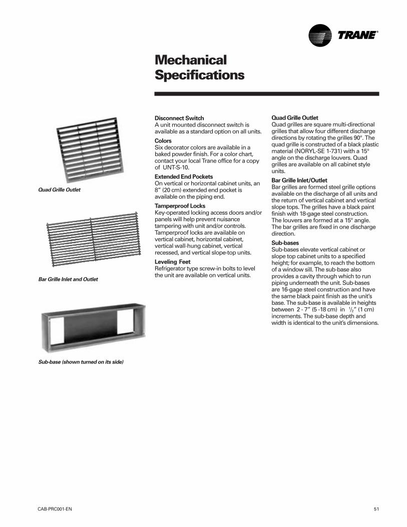
MechanicalSpecifications
CAB-PRC001-EN 51
Disconnect SwitchA unit mounted disconnect switch isavailable as a standard option on all units.
ColorsSix decorator colors are available in abaked powder finish. For a color chart,contact your local Trane office for a copyof UNT-S-10.
Extended End PocketsOn vertical or horizontal cabinet units, an8” (20 cm) extended end pocket isavailable on the piping end.
Tamperproof LocksKey-operated locking access doors and/orpanels will help prevent nuisancetampering with unit and/or controls.Tamperproof locks are available onvertical cabinet, horizontal cabinet,vertical wall-hung cabinet, verticalrecessed, and vertical slope-top units.
Leveling FeetRefrigerator type screw-in bolts to levelthe unit are available on vertical units.
Quad Grille OutletQuad grilles are square multi-directionalgrilles that allow four different dischargedirections by rotating the grilles 90°. Thequad grille is constructed of a black plasticmaterial (NORYL-SE 1-731) with a 15°angle on the discharge louvers. Quadgrilles are available on all cabinet styleunits.
Bar Grille Inlet/OutletBar grilles are formed steel grille optionsavailable on the discharge of all units andthe return of vertical cabinet and verticalslope tops. The grilles have a black paintfinish with 18-gage steel construction.The louvers are formed at a 15° angle.The bar grilles are fixed in one dischargedirection.
Sub-basesSub-bases elevate vertical cabinet orslope top cabinet units to a specifiedheight; for example, to reach the bottomof a window sill. The sub-base alsoprovides a cavity through which to runpiping underneath the unit. Sub-basesare 16-gage steel construction and havethe same black paint finish as the unit’sbase. The sub-base is available in heightsbetween 2 - 7” (5 -18 cm) in 1/2” (1 cm)increments. The sub-base depth andwidth is identical to the unit’s dimensions.
Quad Grille Outlet
Bar Grille Inlet and Outlet
Sub-base (shown turned on its side)
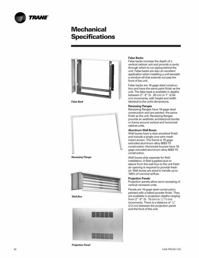
MechanicalSpecifications
CAB-PRC001-EN52
False BacksFalse backs increase the depth of avertical cabinet unit and provide a cavitythrough which to run piping behind theunit. False backs are also an excellentapplication when installing a unit beneatha window sill that extends out past thefront of the unit.
False backs are 18-gage steel construc-tion and have the same paint finish as theunit. The false back is available in depthsbetween 2”- 8” (5 - 20 cm) in 1” (2.54cm) increments, with height and widthidentical to the unit’s dimensions.
Recessing FlangesRecessing flanges have 18-gage steelconstruction and are painted the samefinish as the unit. Recessing flangesprovide an aesthetic architectural borderor frame around vertical and horizontalcabinet units.
Aluminum Wall BoxesWall boxes have a clear anodized finishand include a single core wire meshinsect screen. The frame is 10-gageextruded aluminum alloy 6063-T5construction. Horizontal louvers have 16-gage extruded aluminum alloy 6063-T5construction.
Wall boxes ship separate for fieldinstallation. A field supplied duct orsleeve from the wall box to the unit freshair opening is required to provide freshair. Wall boxes are sized to handle up to100% of nominal airflow.
Projection PanelsProjection panels allow semi-recessing ofvertical recessed units.
Panels are 16-gage steel construction,painted with a baked powder finish. Theyare available in projection depths rangingfrom 2”- 6” (5 - 15 cm) in 1/2”(1 cm)increments. There is a distance of 7/8”(2.2 cm) between the projection paneland the front of the unit.
Recessing Flange
False Back
Wall Box
Projection Panel
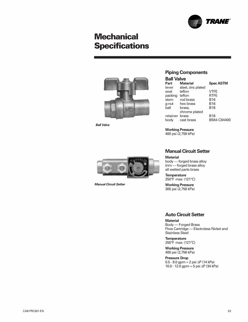
MechanicalSpecifications
CAB-PRC001-EN 53
Piping Components
Ball ValvePart Material Spec ASTMlever steel, zinc platedseat teflon VTFEpacking teflon RTFEstem rod brass B16g-nut hex brass B16ball brass, B16
chrome platedretainer brass B16body cast brass B584-C84400
Working Pressure400 psi (2,758 kPa)
Manual Circuit Setter
Materialbody — forged brass alloytrim — forged brass alloyall wetted parts brass
Temperature250°F max (121°C)
Working Pressure300 psi (2,758 kPa)
Auto Circuit Setter
MaterialBody — Forged BrassFlow Cartridge — Electroless Nickel andStainless Steel
Temperature250°F max (121°C)
Working Pressure400 psi (2,758 kPa)
Pressure Drop0.5 - 9.0 gpm = 2 psi ∆P (14 kPa)10.0 - 12.0 gpm = 5 psi ∆P (34 kPa)
Ball Valve
Manual Circuit Setter
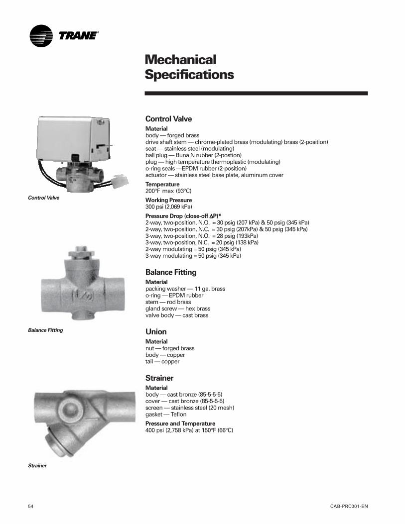
MechanicalSpecifications
CAB-PRC001-EN54
Control Valve
Materialbody — forged brassdrive shaft stem — chrome-plated brass (modulating) brass (2-position)seat — stainless steel (modulating)ball plug — Buna N rubber (2-postion)plug — high temperature thermoplastic (modulating)o-ring seals —EPDM rubber (2-position)actuator — stainless steel base plate, aluminum cover
Temperature200°F max (93°C)
Working Pressure300 psi (2,069 kPa)
Pressure Drop (close-off ∆∆∆∆∆P)*2-way, two-position, N.O. = 30 psig (207 kPa) & 50 psig (345 kPa)2-way, two-position, N.C. = 30 psig (207kPa) & 50 psig (345 kPa)3-way, two-position, N.O. = 28 psig (193kPa)3-way, two-position, N.C. = 20 psig (138 kPa)2-way modulating = 50 psig (345 kPa)3-way modulating = 50 psig (345 kPa)
Balance Fitting
Materialpacking washer — 11 ga. brasso-ring — EPDM rubberstem — rod brassgland screw — hex brassvalve body — cast brass
Union
Materialnut — forged brassbody — coppertail — copper
Strainer
Materialbody — cast bronze (85-5-5-5)cover — cast bronze (85-5-5-5)screen — stainless steel (20 mesh)gasket — Teflon
Pressure and Temperature400 psi (2,758 kPa) at 150°F (66°C)
Control Valve
Balance Fitting
Strainer
a business of American Standard Inc.www.trane.com
For more information contactyour local Trane office ore-mail us at [email protected]
Literature Order Number
File Number
Supersedes
Stocking Location
Trane has a policy of continuous product improvement and reserves the right to change design and specificationswithout notice.
CAB-PRC001-EN
PL-TD-CABPRC001-EN-0303
CAB-PRC001-EN 12/00
La Crosse - Inland Printing

![[Gokigenyou] Flo Flo v.1 C.13](https://cdn.vdocuments.net/doc/165x107/577cdebd1a28ab9e78afba15/gokigenyou-flo-flo-v1-c13.jpg)


