
International Journal of Science, Engineering and Technology Research (IJSETR), Volume 4, Issue 2, February 2015
417
ISSN: 2278 – 7798 All Rights Reserved © 2015 IJSETR
Abstract— This paper presents reduction of line current
harmonics using Four-leg shunt active power filter with
balanced and unbalanced load condition for three phase
four wire shunt active power filter. The synchronous
reference frame (SRF) method is used to extracting
reference current for four-leg shunt active filter. The
Hysteresis current controller (HCC) is used to generate gate
pulses and applied VSI based four –leg shunt active power
filter. Two control methods were used for four-leg shunt
active power filter one is PI and other one is Fuzzy logic
controller. The PI and Fuzzy logic controller to control,
four leg shunt active power filter to compensate line current
harmonics and neutral current compensation to improve
power quality for three-phase four wire system. The main
aim of this paper is to reduce the total harmonic distortion
(THD) in the line current and neutral current
compensation. The MATLAB/Simulink environment is
used to model for above four leg topology of shunt active
power filter.
Index Terms— Shunt active power filter, SRF method,
Hysteresis current controller, PI and Fuzzy logic controller
1. INTRODUCTION
Modern days, three phase four wire distribution power system
has been broadly employed in residential and office buildings,
manufacturing facilities, schools, etc., to supply low level voltage.
The typical loads connected to the three phase four wire power
system may be reasonable three phase non-linear loads such as
motor drives, power electronics loads, large Uninterruptible power
supplies or single phase non-linear loads such as switch-mode
power supplies in computer equipment, inverter air conditioners and
other power electronic related facilities. The common of these loads
have a nonlinear input or unbalanced characteristic, which may
cause two problems such as high input current harmonics and
extreme neutral current. The survival of current harmonics in power
systems increases losses in the lines, decreases the power factor and
causes timing errors in sensitive electronic equipment. The
harmonic currents produced by balanced three phase non-linear
loads are positive-sequence harmonics and negative-sequence
Harmonics. Nevertheless harmonic currents produced by single
phase non-linear loads which are connected phase to neutral in three
phase four wire system are third order zero-sequence harmonics.
Parimala.V Assistant Professor (SG), Department of PG-ES,
P.A College of Engineering and Technology, Pollachi.
Dr.GaneshKumar.D, Professor,
Department of EEE, P.A College of Engineering and Technology, Pollachi.
Renugadevi.V,Department of PG-ES, P.A College Of Engineering and
Technology, Pollachi
Two primary approaches for humanizing power quality are passive
filter and active filter. Passive filters are broadly worn to eliminate
harmonics in power system for its simplicity and low cost still,
passive filters have a number of drawbacks such as large size, tuning
and risk of resonance problems. Now, the 4-leg active filters have
confirmed to be very effective to solve the troubles of current
harmonics, reactive power, unbalanced load current and excessive
neutral current simultaneously in 3-phase 4-wire system, and can be
a much improved solution than conventional passive filters. The
Synchronous Reference Frame (SRF) theory [7] was generally
applied to calculate the compensating currents assume ideal mains
voltages. But, mains voltage may be unbalanced and/or distorted in
industrial systems [1]. So, the Four leg APF using the p-q theory
does not provide good performance .For humanizing the APF
performance under non-ideal mains voltage conditions, various
improved methods based on Instantaneous reactive power theory
have been future even though superior results have been achieved.
However, Instantaneous reactive power methods for harmonic
detection in the three phase four wire systems need
phase-locked-loop (PLL), low-pass filter and the multiple
coordinate transformation[4] .nevertheless, the conventional PI
controller was used for the generation of a reference current
template. The PI controller requires exact linear mathematical
models, which are not easy to attain and fails to perform
satisfactorily under parameter variations, nonlinearity, load
disturbance, etc. Recently, Fuzzy logic controllers (FLC) have
generate a good deal of interest in certain applications[7] The
benefit of Fuzzy logic controller over conventional controllers are
that they do not need accurate mathematical model can work with
imprecise inputs, can hold non-linearity, and are more strong than
conventional controller.
In this work two control methods are used, one is PI and another one
is Fuzzy logic controller (FLC) of shunt active power filter for the
line current harmonics and neutral current compensation of a
nonlinear load. The synchronous reference frame theory is used for
generate reference current in four legs shunt active filter and
hysteresis controller is used to obtaining a gate pulse for shunt active
power filter. A design criterion is described in the selection of power
circuit components.
Both the control schemed is compared and performance of both the
controllers the fuzzy controller has a less line current harmonics
THD values compared to PI controller A detailed simulation
program of the schemes is developed to predict the performance for
different conditions and Simulink models also has been developed
for the same for different parameters and operating conditions.
Fig.1.1.Four-leg shunt APF with non-linear loads
FOUR-LEG SHUNT ACTIVE POWER FILTER
FOR POWER QUALITY IMPROVEMENT
USING PI AND FUZZY CONTROLLERS
V.Parimala, Dr.D.GaneshKumar, V.Renugadevi
International Journal of Science, Engineering and Technology Research (IJSETR), Volume 4, Issue 2, February 2015
418
ISSN: 2278 – 7798 All Rights Reserved © 2015 IJSETR
2. SHUNT ACTIVE FILTER
2.1. Introduction:
In this case the shunt active power filter operates as a current
source injecting the harmonic components generate by the load but
phase-shifted by 180. The main idea of the 4-leg APF is to
compensate harmonics, reactive power, and neutral current and
unbalanced loads .In 3-phase 4-wire systems, two kinds of VSI
topologies since 4-leg inverter and three leg inverter (split capacitor)
are used. The 4-leg inverter employed 1-leg specially to compensate
neutral current. Fig 1 shows the basic compensation principle of the
shunt APF.
A shunt APF is designed to be connected in parallel with the load,
to detect its harmonic current and to inject into the system a
compensating current, equal with the load harmonic current.
Therefore, the current strained from the power system at the
coupling point of the filter will result in sinusoidal.
2.2. Basic compensation principles:
The active power filter is controlled to deliver the compensating
current if from/to the load to nullify the current harmonics on the AC
side and reactive power flow from/to the source there by making the
source current in phase with source voltage. Figure 3.2 shows the
basic compensation principle of the active power filter and it serve
as an energy storage element to bring the real power difference
between load and source during the transient period. When the load
condition change the real power balance between the mains and the
load will be concerned. This real power distinction is to be
compensated by the DC capacitor.
These adjust the DC capacitor voltage away from the reference
voltage. In categorize to keep suitable operation or the active filter,
the peak value of the orientation, source current must be familiar to
proportionally alter the real power drawn from the source. These
real powers charged/discharged by the capacitor compensate the real
power dissimilarity between the consumed by the load and that of
supplied by the source. If the DC capacitor voltage is improved and
attains the reference voltage, the real power absolute from the source
is imaginary to be equivalent to that consumed by the load again.
Fig .2.1.Basic configuration of shunt active filter.
3. CONTROL STATERGIES
3.1. SYNCHRONOUS REFERENCE FRAME (d-q)
THEORY
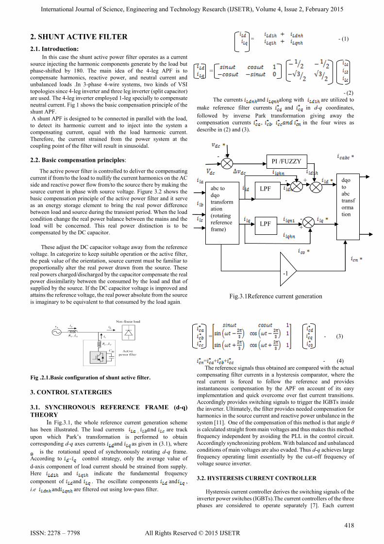
In Fig.3.1, the whole reference current generation scheme
has been illustrated. The load currents nd are track
upon which Park‘s transformation is performed to obtain
corresponding d-q axes currents and as given in (3.1), where
ɷ is the rotational speed of synchronously rotating d-q frame.
According to - control strategy, only the average value of
d-axis component of load current should be strained from supply.
Here and indicate the fundamental frequency
component of and . The oscillate components and ,
i.e and are filtered out using low-pass filter.
= - (1)
=
- (2)
The currents and along with are utilized to
make reference filter currents and in d-q coordinates,
followed by inverse Park transformation giving away the
compensation currents , in the four wires as
describe in (2) and (3).
- +
- +
+
-
+
-1
Fig.3.1Reference current generation
= - (3)
= + + - (4)
The reference signals thus obtained are compared with the actual
compensating filter currents in a hysteresis comparator, where the
real current is forced to follow the reference and provides
instantaneous compensation by the APF on account of its easy
implementation and quick overcome over fast current transitions.
Accordingly provides switching signals to trigger the IGBTs inside
the inverter. Ultimately, the filter provides needed compensation for
harmonics in the source current and reactive power unbalance in the
system [11]. One of the compensation of this method is that angle θ
is calculated straight from main voltages and thus makes this method
frequency independent by avoiding the PLL in the control circuit.
Accordingly synchronizing problem. With balanced and unbalanced
conditions of main voltages are also evaded. Thus d-q achieves large
frequency operating limit essentially by the cut-off frequency of
voltage source inverter.
3.2. HYSTERESIS CURRENT CONTROLLER
Hysteresis current controller derives the switching signals of the
inverter power switches (IGBTs).The current controllers of the three
phases are considered to operate separately [7]. Each current
PI /FUZZY
abc to
dqo
transform
ation
(rotating
reference
frame)
LPF
LPF
dqo
to
abc
transf
orma
tion

International Journal of Science, Engineering and Technology Research (IJSETR), Volume 4, Issue 2, February 2015
419
ISSN: 2278 – 7798 All Rights Reserved © 2015 IJSETR
controller determines the switching signals to the inverter bridge
.The switching logic for phase A is formulated as follows
If - HB upper switch is OFF and lower switch is
ON.
If upper switch is ON and lower switch is
OFF
In an identical manner, the switching logic for devices in phase
B and C are derived. The switches are restricted asynchronously to
ramp the current through the inductor up and down so that it follows
the reference. The current ramping up and down linking the two
limits is illustrated in fig.3.3.When the current during the inductor
surpasses the upper hysteresis limit a negative voltage is applied by
the inverter to the inductor. The beginning the current in the
inductor to reduce. Once the current reaches the lower hysteresis
limit a positive voltage is applied by the inverter to the inductor and
this causes the current to boost and the cycle repeats.
Figure.3.2.Hysteresis current waveform
3.3. PI controller:
The control scheme consists of a PI controller, a limiter, and a
three phase sine wave generator for the reference current and
switching signal generation. The real value of the reference currents
is estimated by regulating the DC link voltage. The real capacitor
voltage is compared with a set reference value[7]
The error signal is then processed through a PI controller, which
supply to the zero steady error in tracking the reference current
signal. The output of the PI controller is measured as the peak value
of the supply current (Imax), which is composed of two
components: (a) the fundamental active power component of the
load current, and (b) the loss component of the APF; to maintain the
average capacitor voltage at a constant value. The peak value of the
current (Imax) so attained, is multiplied by the unit sine vectors in
phase with the respective source voltages to obtain the reference
compensating currents. These estimated reference currents (Isa*,
Isb*, and Isc*,Isn, Isn*) and the sensed actual currents ( Isa, Isb, and Isc ,
Isn) are compared to a hysteresis controller, which gives the error
signal for the modulation technique. This error signal decides the
operation of the inverter switches.
3.4 Fuzzy controller:
The control scheme consists of Fuzzy controller, limiter and
three phase sine wave generator for the reference current generation
and generation of switching signals. The crest value of reference
currents is estimated by regulating the DC link voltage. The real
capacitor voltage is compared with a set reference value. The error
signal is then processed during a Fuzzy controller, which supply to
zero steady error in tracking the reference current signal [10].
A fuzzy controller converts a linguistic control strategy into an
automatic control strategy, and fuzzy rules are constructed by expert
experience or knowledge database. Firstly, input voltage Vdc and
the input reference voltage Vdc-ref have been placed of the angular
velocity to be the input variables of the fuzzy logic controller. Then
the output variable of the fuzzy logic controller is presented by the
control Current Imax. To change these numerical variables into
linguistic variables, the subsequent seven fuzzy levels or sets are
chosen as:
NB (negative big), NM (negative medium), NS (negative
small), ZE (zero), PS (positive small), PM (positive medium), and
PB (positive big) as shown in 3.4(a).
The fuzzy controller is characterized as follows:
1) Seven fuzzy sets for each input and output;
2) Fuzzification using continuous universe of discourse;
3) Implication using Mamdani's ‗min‘ operator;
4) De-fuzzification using the ‗centroid‘ method.
( a)
(b)
(c)
Fig.3.3.(a) Input Vdc normalized membership function; (b)
Input Vdc-ref Normalized Membership Function; (c) Output
Imax Normalized Membership Function.
4. SIMULATION RESULTS:
The simulation is carried out with three phase four wire system
with non-linear load. Here the diode rectifier is used as non-linear
load. The Fig-4 shows the circuit diagram without any filter or
controller circuit. From this simulation, source current, voltages are
taken as the output. The THD value of source current under
balanced and unbalanced source condition. The THD value is high
because we won‘t use any controller in this circuit.
Fig 4.1.Simulation for open loop system
International Journal of Science, Engineering and Technology Research (IJSETR), Volume 4, Issue 2, February 2015
420
ISSN: 2278 – 7798 All Rights Reserved © 2015 IJSETR
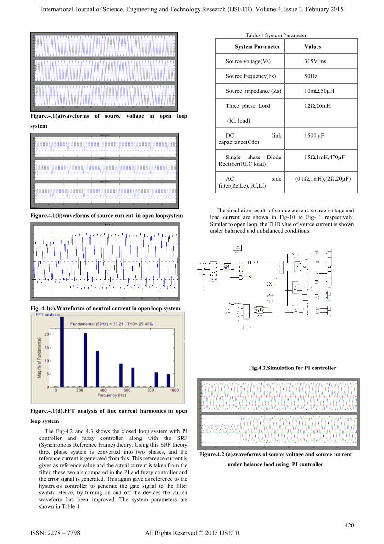
Figure.4.1(a)waveforms of source voltage in open loop
system
Figure.4.1(b)waveforms of source current in open loopsystem
Fig. 4.1(c).Waveforms of neutral current in open loop system.
Figure.4.1(d).FFT analysis of line current harmonics in open
loop system
The Fig-4.2 and 4.3 shows the closed loop system with PI
controller and fuzzy controller along with the SRF
(Synchronous Reference Frame) theory. Using this SRF theory
three phase system is converted into two phases, and the
reference current is generated from this. This reference current is
given as reference value and the actual current is taken from the
filter; these two are compared in the PI and fuzzy controller and
the error signal is generated. This again gave as reference to the
hysteresis controller to generate the gate signal to the filter
switch. Hence, by turning on and off the devices the curren
waveform has been improved. The system parameters are
shown in Table-1
Table-1 System Parameter
System Parameter Values
Source voltage(Vs) 315Vrms
Source frequency(Fs) 50Hz
Source impedance (Zs) 10mΩ,50µH
Three phase Load
(RL load)
12Ω,20mH
DC link
capacitance(Cdc)
1500 µF
Single phase Diode
Rectifier(RLC load)
15Ω,1mH,470µF
AC side
filter(Rc,Lc),(Rf,Lf)
(0.1Ω,1mH),(2Ω,20µF)
The simulation results of source current, source voltage and
load current are shown in Fig-10 to Fig-11 respectively.
Similar to open loop, the THD vlue of source current is shown
under balanced and unbalanced conditions.
Fig.4.2.Simulation for PI controller
Figure.4.2 (a).waveforms of source voltage and source current
under balance load using PI controller

International Journal of Science, Engineering and Technology Research (IJSETR), Volume 4, Issue 2, February 2015
421
ISSN: 2278 – 7798 All Rights Reserved © 2015 IJSETR
Fig.4.2(b).Waveforms of DC link voltage and neutral current
under balanced load using PI controller
Figure.4.2 (c).FFT analysis of line current harmonics under
balanced load using PI controller
Figure.4.2.(d).waveforms of source voltage and source current
under unbalanced load using PI controller
Fig.4.2.(e).Waveforms of DC link voltage and neutral current
under balanced load using PI controller
Figure.4.2.(f).FFT analysis of line current under unbalanced
load using PI controller
Figure 4.3. Simulation diagram for fuzzy controller
Fig.4.3(a).waveforms of source voltage and source current
under balanced load using Fuzzy logic controller.
Fig.4.3(b).Waveforms of dc link voltage and neutral current
under balanced load using Fuzzy logic controller
Fig.4.3(c).FFT analysis of line current under balanced load
using Fuzzy logic controller.
International Journal of Science, Engineering and Technology Research (IJSETR), Volume 4, Issue 2, February 2015
422
ISSN: 2278 – 7798 All Rights Reserved © 2015 IJSETR
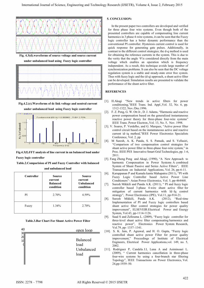
Fig. 4.3(d).waveforms of source voltage and source current
under unbalanced load using Fuzzy logic controller
Fig.4.2.(e).Waveforms of dc link voltage and neutral current
under unbalanced load using Fuzzy logic controller
Fig.4.3(f).FFT analysis of line current in un balanced load under
Fuzzy logic controller
Table.2.Comparision of PI and Fuzzy Controller with balanced
and unbalanced load
Controller Source
current
Balanced
condition
Source
current
Unbalanced
condition
PI 2.70% 4.59%
Fuzzy 1.34% 2.70%
Table.3.Bar Chart For Shunt Active Power Filter
010203040 open loop
Balanced
load
Unbalanced
load
5. CONCLUSION:
In the present paper two controllers are developed and verified
for three phase four wire systems. Even though both of the
presented controllers are capable of compensating line current
harmonics in 3 phase 4-wire systems, it can be seen that the Fuzzy
logic controller has a better dynamic performance than the
conventional PI controller. Hysteresis current control is used for
quick response for generating gate pulses. Additionally, in
contrast to the different control strategies; the d-q method is used
for obtaining the reference currents in the system. This is due to
the verity that the angle ‗θ‘is considered directly from the main
voltage which enables an operation which is frequency
independent. As a result, this technique avoids large number of
synchronization problems. It can also be seen that the DC voltage
regulation system is a stable and steady-state error free system.
Thus with fuzzy logic and the (d-q) approach, a shunt active filter
can be developed. Simulation results are presented to validate the
performance of the shunt active filter.
REFERENCES
[1]. H.Akagi ―New trends in active filters for power
conditioning,‖IEEE Trans. Ind. Appl.,Vol. 32, No. 6, pp.
1312-1322, Nov./Dec.1996.
[2]. F. Z. Peng, G. W. Ott Jr., D. J. Adams, ―Harmonic and reactive
power compensation based on the generalized instantaneous
reactive power theory for three-phase four-wire systems‖
IEEE Trans. Power Electron.,Vol. 13, No. 5, Nov. 1998.
[3]. V. Soares, P. Verdelho, and G. Marques, ―Active power filter
control circuit based on the instantaneous active and reactive
current id–iq method,‖IEEE Power Electronics Specialists
Conference, Vol. 2, pp
[4]. M Suresh, A. K. Panda, S. S. Patnaik, and S. Yellasiri,
―Comparison of two compensation control strategies for
shunt active power filter in three-phase four-wire system,‖ in
Proc. IEEE PES Innovative Smart Grid Technologies, pp. 1-6,
2011.
[5]. Fang Zheng Peng and Akagi, (1990), ―A New Approach to
harmonic Compensation in Power Systems A combined
System of Shunt Passive and Series Active Filters‖, IEEE
Transactions on Industrial Applications, Vol. 26, pp-6-11.
[6]. Karuppanan P and Kamala kanta Mahapatra (2011), ―PI with
Fuzzy Logic Controller based Active Power Line
Condtioners‖- Asian Power Electronics, Vol. 5, pp-464468.
[7]. Suresh Mikkili and Panda A.K. (2011), ― PI and fuzzy logic
controller based 3-phase 4-wire shunt active filter for
mitigation of current harmonics with Id–Iq control
strategy‖, Power Electronics (JPE), Vol.11, pp-914-21.
[8]. Suresh Mikkili, Panda A.K. (2012), ―Real-time
Implementation of PI and Fuzzy logic controllers based
shunt active filter control strategies for power quality
improvement‖, ELSEVEIR:Electrical Power and Energy
System, Vol.43, pp-1114-1126.
[9]. Saad S and Zellouma L. (2009), ―Fuzzy logic controller for
three-level shunt active filter compensating harmonics and
reactive power‖, Electronics Power System Research,
Vol.79, pp- 1337–1341.
[10]. S. K. Jain, P. Agrawal, and H. O. Gupta, ―Fuzzy logic
controlled shunt active power Filter for power quality
improvement,‖ Proceedings of Institute of Electrical
Engineers, Electrical Power Applications,vol. 149, no. 5,
2002.
[11]. Rodriguez P, Candela J.I, Luna A and Asiminoaei L.
(2009), ― Current harmonics cancellation in three-phase
four-wire systems by using a four-branch star filtering
Topology‖, IEEE Transactions on Power Electronics, Vol.
24,pp-1939–50.

International Journal of Science, Engineering and Technology Research (IJSETR), Volume 4, Issue 2, February 2015
423
ISSN: 2278 – 7798 All Rights Reserved © 2015 IJSETR
[12]. Kirawanich P and O, Connell R.M. (2004), ―Fuzzy Logic
Control of an Active Power Line Condioner‖, (2004), IEEE
Transactions on Power Electronics, Vol. 19, pp-1574-1585.
Bibliography:
V.Parimala has obtained her Bachelor of
Engineering Degree in Electrical and Electronics
Engineering from Madras University. Master‘s
Degree in Power Electronics and Drives from Anna
University. Currently working as Senior Assistant
Professor. Her area of interests includes Power
Quality, Power Electronics, Soft Computing
Techniques and Virtual Instrumentation.
Dr.D.Ganeshkumar has obtained his Bachelor
of Engineering Degree in Electronics and
Instrumentation and Master in Applied
Electronics. He has received his PhD in Vibration
Analysis using Virtual Instrumentation. Principle
investigator for DST, Government of India
funded project or Sound and Vibration Analysis
in Electrical Machines using Virtual
Instrumentation Techniques. His area of interest includes Process
Monitoring and Control in Virtual Instrumentation Systems.
V.RENUGADEVI has obtained her Bachelor‘s
degree in Electrical and Electronics
Engineering from Sri Eshwar College of
engineering and currently pursuing her Master‘s
degree in Power Electronics and Drives from P.A.
College of Engineering and Technology. Her area
of interest includes Power Quality and Drives.


