Linear State Estimator in Next Generation EMS Joe Betro, PG&E Anil Jampala, Alstom March 28, 2013
Presenters:
Joe Betro, PG&E Anil K. JAMPALA, Alstom

Contributors
PG&E
Vahid Madani
Washington State University
Prof. Anjan Bose, Lin Zhang
Alstom
Jay Giri, John Wulf, Vijay Sukhavasi, Manu Parashar, Barbara Motteler, Mohamed Elmesai

Out-line
Motivation
Concurrent work
LSE in PG&E SGIG Project
Test Results
Q & A

Motivation
Traditional SE – Background
PG&E EMS network model – 4,000+ buses
Typical periodicity: 2 minutes
Typical Execution time – under 30 seconds
Next Generation EMS Applications using SynchroPhasor data
Long-term direction:
• State Measurement
Today:
• Hybrid State Estimator
• Linear State Estimator (LSE)
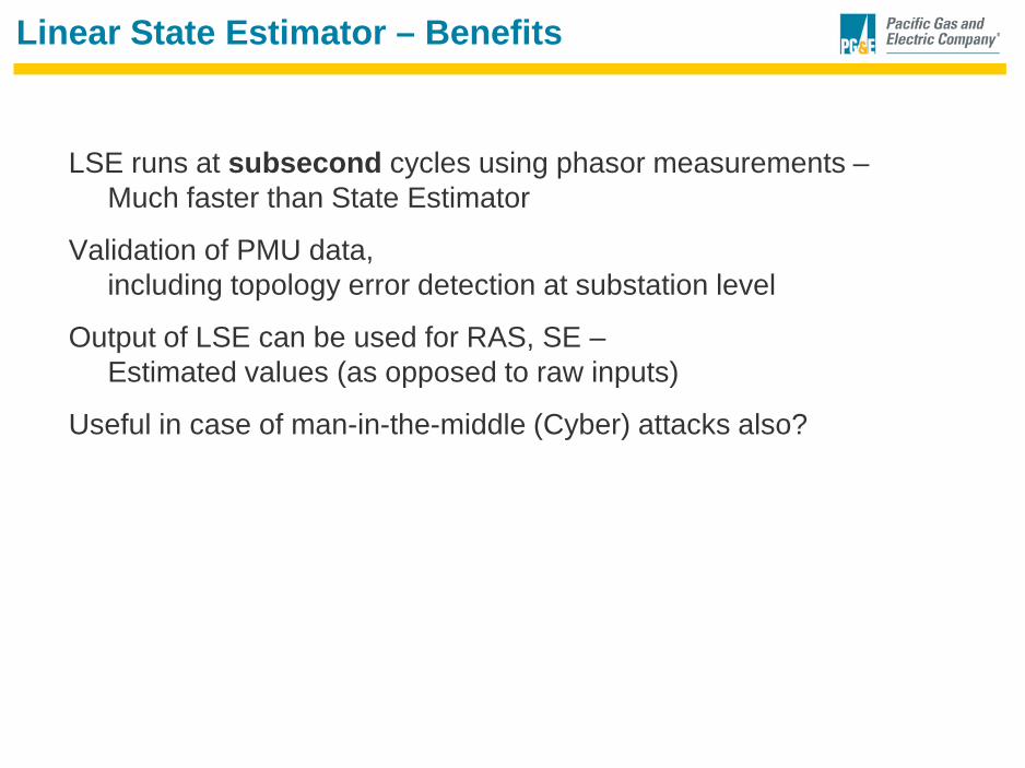
Linear State Estimator – Benefits
LSE runs at subsecond cycles using phasor measurements – Much faster than State Estimator
Validation of PMU data, including topology error detection at substation level
Output of LSE can be used for RAS, SE – Estimated values (as opposed to raw inputs)
Useful in case of man-in-the-middle (Cyber) attacks also?

Concurrent Work in LSE Area
Virginia Tech [Dominion & Quanta]
Georgia Tech [also with PG&E]
RPI
WSU [also with PG&E/Alstom]
Others??
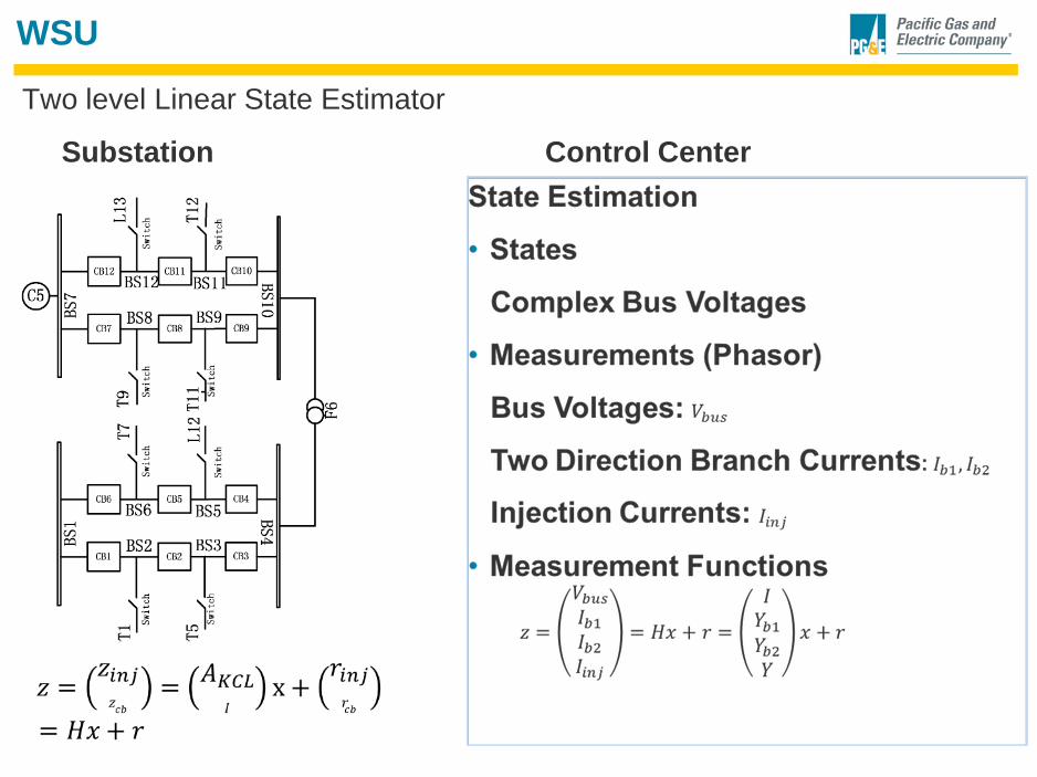
WSU
Two level Linear State Estimator
Substation Control Center
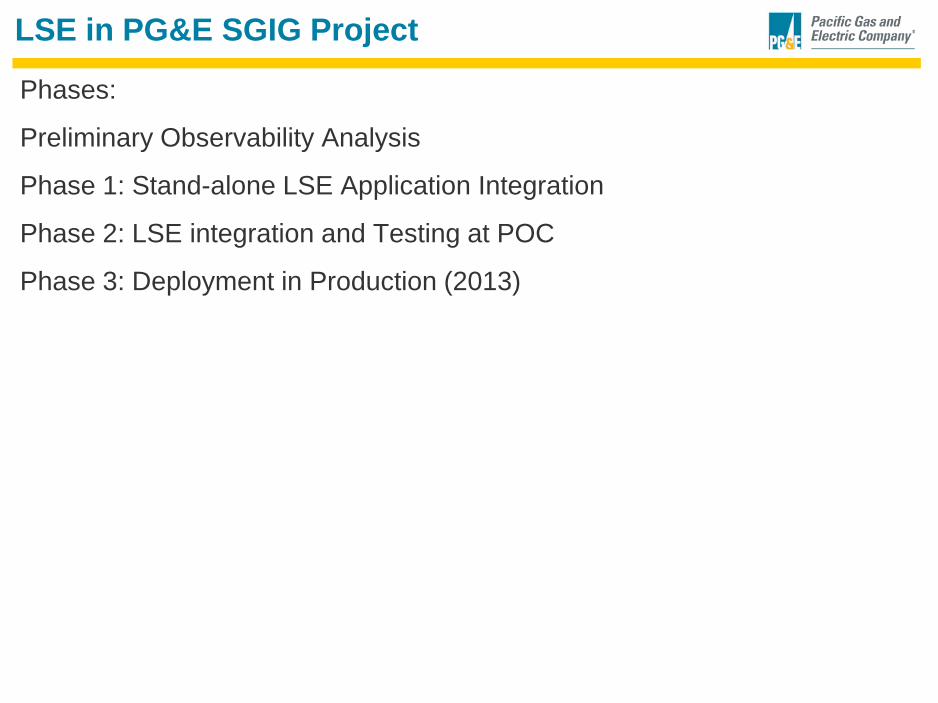
LSE in PG&E SGIG Project
Phases:
Preliminary Observability Analysis
Phase 1: Stand-alone LSE Application Integration
Phase 2: LSE integration and Testing at POC
Phase 3: Deployment in Production (2013)

14
Proof of Concept Testing - Architecture
PG&E Synchrophasor Project – Proof of Concept ArchitectureC37.118 is used for interim testing while harmonization with IEC 61850 is demonstrated
EMS 1
SSD = Solid State Disk
30/60 datasets/sFrom SSE - TBD
BLUE – C37.118Via Ethernet
EngineeringVisualization
PROTOCOLS
PMU 1
120 phasors/s 100Mb Switches
Substation PDC-1
SubStateEstimator-1Historian
Substation PDC-2
SubStateEstimator-2Historian
PMU 2
Test Analogs
Remote ClientTest Receiver
Super – PDC 1
SSD
EMSVisualization
Noise Generator
EMS 2
60 datasets/s
1 dataset/s60 datasets/s 1 dataset/s
Super -PDC 2
CommunicationNetwork
PMU 5
BLACK – VendorSpecific
100Mb Switches
IEC 61850-based Phasor Gateway
RemoteClients
CAISO/ WECC
Interface
DAS 2
Ancillary PDC 2
DAS 1
Ancillary PDC 1
Data Synchronization
PMU 5 PMU 6 PMU 3 PMU 7 PMU 8
PMU Emulator
PDC tester
PMU 4
External Visualtization Client
DAS: Data Archival System
GPS Clock
100Mb Switches IRIG-B
IRIG-B15881588
PMU Emulator
DFR PMU
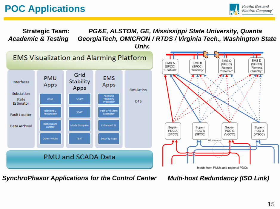
POC Applications
15
Strategic Team: PG&E, ALSTOM, GE, Mississippi State University, Quanta Academic & Testing GeorgiaTech, OMICRON / RTDS / Virginia Tech., Washington State
Univ.
SynchroPhasor Applications for the Control Center Multi-host Redundancy (ISD Link)

LSE Application Context

LSE Application
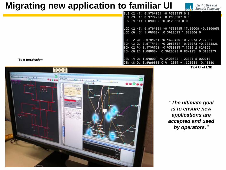
Migrating new application to familiar UI
Text UI of LSE
To e-terraVision
“The ultimate goal is to ensure new applications are
accepted and used by operators.”
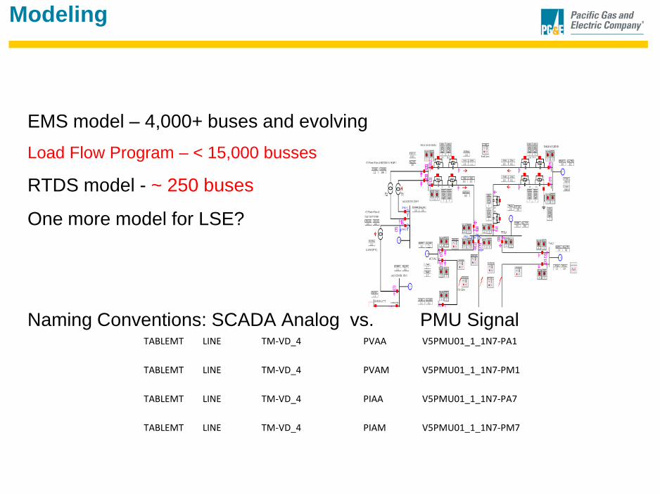
Modeling
EMS model – 4,000+ buses and evolving Load Flow Program – < 15,000 busses
RTDS model - ~ 250 buses
One more model for LSE?
Naming Conventions: SCADA Analog vs. PMU Signal
TABLEMT LINE TM-VD_4 PVAA V5PMU01_1_1N7-PA1
TABLEMT LINE TM-VD_4 PVAM V5PMU01_1_1N7-PM1
TABLEMT LINE TM-VD_4 PIAA V5PMU01_1_1N7-PA7
TABLEMT LINE TM-VD_4 PIAM V5PMU01_1_1N7-PM7

LSE Model (cont)
Subset of EMS model
Need for Breaker Status
Substation SE – limited by PMU information
Line side PMUs
Use of Pseudo Measurements

Migrating new applications to a production EMS
• Redundant configuration
• Study version of application
• Training
• Re-inventing the wheel
• Product Life Cycle Maintenance
• Algorithm
21
• The Development Environment
• The User Interface
• Where should the application reside?
• Inputs and Outputs
• Application Program Interface (API)
• Security and Administration

LSE Testing
Standalone Testing
Use of Virtual PMUs in PG&E SynchroPhasor Test Facility
Nearly 100 Test scenario
Validation with the EMS State Estimator

LSE Test – Scenario 1 – Basecase – Voltage Magnitude
510
515
520
525
530
535
540
545
550
1 2 3 4 5 6 7 8 9 10 11 12 13 14 15 16 17
Voltage Magnitude
Voltage Magnitude Estimated

LSE Test – Scenario 1 – Basecase - Angles
0
5
10
15
20
25
1 2 3 4 5 6 7 8 9 10 11 12 13 14 15 16 17
Voltage Angle
Voltage Angle Estimated

LSE Test – Scenario 2 – Magnitude error detection
480
500
520
540
560
580
600
620
1 2 3 4 5 6 7 8 9 10 11 12 13 14 15 16 17 18 19 20 21 22 23 24 25 26 27 28 29 30 31
Voltage Magnitude Voltage Magnitude Estimated


LSE Test – Scenario 4 – Measaurements Switched
Current Mag (Meas)
Current Mag (Est)
Current Angle (Meas)
Current Angle (Est)

Framework – Parallel State Estimator
SCADA (with
PMUs)
Network model
(without PMUs)
Network model (with
PMUs)
Compare both Solutions
Parallel State Estimator
State Estimator

Summary
• Review of LSE
• Getting ready for Field testing

The Knee Moment (It Works!)


