CI/SfB(4-) Rh2
UK September 2008
I nsu la ted Pane ls
Approved to LPS 1181Certificate No. 186a & 260a
Insulated Slate and Tile Support System Installation Guide
Tile Support
I N S U L A T E D R O O F S Y S T E M S

2
This document describes in full the installationprocedures and good practice which should beadhered to when installing the Kingspan KS1000 TSInsulated Slate and Tile Support system.
This installation guide should be read inconjunction with the ‘project specific’ designdrawings and method statements.
Care should be taken to ensure that this guide isread and understood in its entirety prior to any sitework commencement.
Should any procedure not be understood, or, if theworks being undertaken are not covered by thisguide, please consult Kingspan envirocare®
Technical Services on 0800 5870090.
This guide is to supplement the training courseoffered to all installers by Kingspan, which isrecommended prior to any product installation.
Installation details given in this document are‘current’ recommendations for Part L2 BuildingRegulations (England & Wales) and Section 6(Scotland) compliance effective from April 2006 and those required for compliance with LPCBcertified systems.
It is the responsibility of the fixing contractor toensure that ‘project specific’ details are compliantto Part L2 Building Regulations (England & Wales)and Section 6 (Scotland), prior to any siteinstallation.
Safety IssuesThe installation of roof and wall panels on anybuilding must be planned carefully to ensure thework can proceed in safety.
The roofing and cladding contractor must carry out the necessary ‘Risk Assessments’ and preparethe ‘Method Statements’ to suit each particularproject for their client taking into account thedetailed fixing recommendations of this installationguide. This method statement should indicate whois responsible for safety, and particularly what safetyequipment will be used for each stage of the workand the sequence of work from delivery toinstallation to ensure compliance with ‘current’CDM, health and safety issues/requirements for thesafety of site operatives.
Introduction
3
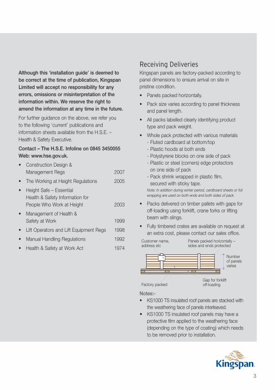
Customer name,address etc
Panels packed horizontally –sides and ends protected
Numberof panelsvaries
Factory packedGap for forkliftoff-loading
Notes:-• KS1000 TS insulated roof panels are stacked with
the weathering face of panels interleaved.• KS1000 TS insulated roof panels may have a
protective film applied to the weathering face(depending on the type of coating) which needsto be removed prior to installation.
Although this ‘installation guide’ is deemed tobe correct at the time of publication, KingspanLimited will accept no responsibility for anyerrors, omissions or misinterpretation of theinformation within. We reserve the right toamend the information at any time in the future.
For further guidance on the above, we refer you to the following ‘current’ publications andinformation sheets available from the H.S.E. –Health & Safety Executive.
Contact – The H.S.E. Infoline on 0845 3450055Web: www.hse.gov.uk.
• Construction Design &Management Regs 2007
• The Working at Height Regulations 2005
• Height Safe – Essential Health & Safety Information forPeople Who Work at Height 2003
• Management of Health &Safety at Work 1999
• Lift Operators and Lift Equipment Regs 1998
• Manual Handling Regulations 1992
• Health & Safety at Work Act 1974
Receiving DeliveriesKingspan panels are factory-packed according topanel dimensions to ensure arrival on site in pristine condition.
• Panels packed horizontally.
• Pack size varies according to panel thicknessand panel length.
• All packs labelled clearly identifying producttype and pack weight.
• Whole pack protected with various materials- Fluted cardboard at bottom/top- Plastic hoods at both ends- Polystyrene blocks on one side of pack- Plastic or steel (corners) edge protectors
on one side of pack- Pack shrink wrapped in plastic film,
secured with sticky tape.Note: In addition during winter period, cardboard sheets or foilwrapping are used on both ends and both sides of pack.
• Packs delivered on timber pallets with gaps foroff-loading using forklift, crane forks or liftingbeam with slings.
• Fully timbered crates are available on request atan extra cost, please contact our sales office.

4
Delivery and Off-loadingTransportation of panel packs to site is by roadtransport. It is the customer’s responsibility tocheck the site for restrictions (i.e. entrance to site,power lines etc.) and agree a storage area to beused, also to identify the correct type/method ofoff-loading/hoisting facilities to be used i.e. crane,crane forks, lifting beam with slings, forklift orspecialist lifting equipment.
Always check the ‘current’ certification of the crane,crane forks, lifting beam, slings, forklift or specialistlifting equipment prior to carrying out off-loading/hoisting operation (i.e. with correct ‘current’SWL Certification).
Site Handling & Storage
*Packs of panels up to 9 metres can be safely off-loaded with frontloaders with the following provisions:
1. Minimum number of panels in a pack is 3.
2. Ground to be level and reasonably firm.
3. Speed of truck to be 5mph maximum – Extreme care to be taken.
Lifting beam for packsover 9 metres
✓Flat slingsnot chains
Protectedges &corners
Forklift for packsunder 9 metres*
Must support panels evenly
Protect panelshere
Protectedges &corners
Less than or equal to 9m*
2m max 2m max3m max 3m max
✗
Must support panels evenly
✗May causedamage to panels

5
Safe StorageTo ensure panels remain in prime condition whilestored onsite, the following precautions should be taken:
At ground level:-
• Allocate safe, clean, trade-free area.
• Prevent personnel from walking over packs.
• Store panels on a slight slope ensuring anypenetrating rainwater drains off.
• Inspect packs regularly.
• Where panels are to be stored for more than 3 months, call the Kingspan envirocare®
Technical Services on 0800 5870090.
Removal of Packaging and Disposal• Preferably at ground level in a designated
area/safe working environment.orAlternatively at roof level, depending on roofpitch, in a designated area/safe workingenvironment with correct method of access.
• Using a suitable knife/blade carefully cut thepack open and remove plastic film/hoods,cardboard, polystyrene, timber etc. and disposein the ‘correct’ allocated waste disposal skip.Note: Some sites will operate a recycling scheme for waste materials.
• Exercise caution when opening packs stored atan angle. There is a danger of panels sliding tothe side and in the direction of slope.
• Individual panels will have low tack adhesivetabs in between and some may have protectivefilm applied (depending on the type of coating)which needs to be removed prior to installation.
• Packs of panels that have had the packagingremoved at ground level and need to be lifted tothe roof level, will require ‘banding’. A proprietyband/sling system should be used, taking carenot to damage the panels.
Movement and Lifting of Panels• The weight of individual panels for lifting can be
determined from the information on page 6 or inour Design and Construction Guide. Werecommend the use of mechanical handlingsystems for the movement and lifting of panelsinto position.
• Individual panels should always be handledcarefully. They should be lifted from a pack andnot dragged/slid over one another. Roof panelsshould not be lifted by the end lap.
At roof level:-
• When storing panel packs at roof level,depending on roof pitch, check that thesub-structure is sufficient and capable ofsupporting the weight of the packs.
• Prior to installation panel packs must besecurely tied to the roof structure to preventmovement.
Slope to drain water off panels
2m 2m

6
ApplicationThe KS1000 TS Insulated Slate and Tile Supportroof system is suitable for all building applicationsand is used in conjunction with Slates and Tiles.For minimum roof pitch consult Slate/Tilemanufacturer.
Product Data
Product Tolerance Panel End Cut BackAll panels are normally produced with a minimumcut back of 10mm. Cut backs up to 175mm canalso be manufactured. If flush ended panels (no cutback) are required they can be manufactured withone end flush and a 10mm cut back on theopposite end, based on panels exceeding 1.8m inlength. The recommended cut back for panel endlapping is 150mm. Panels less than 1.8m longwhich require a cut back can be provided, but willbe charged at full 1.8m price, plus cutting cost.
Available LengthsStandard lengths 1.8 to 12 metres. 12 to 29 metrescan be supplied but may be subject to a transportsurcharge.Note: Panels less than 1.8m long which require a cut back can beprovided, but will be charged at full 1.8m price, plus cutting cost.
A - Core Thickness (mm) 40 50 60 80* 100*
B - Overall Dimension (mm) 75 85 95 115 135
Weight kg/m2 0.5/0.4 steel 9.9 10.3 10.7 11.5 12.3*These panel thicknesses are recommended for Part L2 (England & Wales) and Section 6 (Scotland)based on the minimum U-value requirement
Cut to Length -0.05% +0.1%Liner Sheet Length -0.1% +0.1%Cover Width -0mm +3mmThickness -2mm +2mmEnd Square -3mm +3mm
1000mm cover width333mm 333mm 333mm
AB
Dimensions & Weight
Panel length
Cut back
Product Reference Application DescriptionKS1000 TS* Slate/tile roof panel with
Loss Prevention CertificationBoard (LPCB) approval for roof applications.
*providing slate/tile weight is less than 54kg/m2
Approved to LPS 1181RW Certificate No. 186a & 260a
ECO

7
KS1000 TS Insulated Roof Panel
Components
4mm Ø8mm Ø 6mm Ø
Primary/Main Fastener Secondary/Stitching Screws
Butyl Rubber TapeSealantsRidge Batten
Tile/Slate Batten
Recommended Batten Fasteners
Ridge Batten Support
Flashing
Batten Support Flashing
Gun-Grade SealantFire Rated CanisterInsulation

8
Safety Recommendations1 Good practice recommends a fully boarded
scaffold around the perimeter of the building withloading platforms for panels, triple hand rail’s andtoe boards or propriety hand rail type system, aswell as walkway stagings and safety nets, toensure compliance with ‘current’ CDM, health &safety issues/requirements.
2 We advise caution when loading packs of panelsonto purlins (Kingspan Multibeams), especially ifthe roof pitch exceeds 8°. Panels must besecurely tied to the roof structure to preventmovement.
3 We recommend the use of mechanical handlingsystems for the movement and lifting of panelsinto position. Always check the ‘current’certification of the crane, crane forks, lifting beam,slings, forklift or specialist lifting equipment prior tocarrying out off-loading/hoisting operation (i.e.with correct ‘current’ SWL Certification).
4 Personal protective equipment and clothingshould be worn including gloves to avoid cutsand abrasions to operatives.
5 We recommend that any panel cutting done onsite is preferably carried out at ground level oralternatively at roof level depending on roof pitchin a designated area/safe working environment.
Before Installing Panels1 Before starting any project it is important that
the project specific contract drawings areavailable on site, giving the details at thevarious interfaces on the project. (i.e. eaves,ridge, verge etc.), including the panel fastenerrequirement diagram giving the exact fixingtype, quantity and location.
2 Prior to commencing any installation theconfiguration and dimensional accuracy of thesupporting structure should be compared withthe approved plan drawings.
3 Check roof pitch is a minimum to suit type ofslate/tile system being used.
4 Steel (or timber) must be lined and levelled inaccordance with the requirements of the contractdocument. Check the roof steelwork visually forany damage or distortion, paying particularattention to lines of purlin that will support panelends. Where these are bowed or distorted so thatthey do not give a straight bearing surface of50mm min width, flange extension plates will be required.
Valley and boundary wall gutters must be securelyfixed in position where applicable.
One Panel Eaves to Ridge

9
5 As work progresses across the roof, areas tobe regularly walked over or where materialsare to temporarily stored should be identifiedand protected. Traffic should use walkwaysto avoid damaging the finish on the panels.
At all times during the fitting of the roof, thepainted panel surface must be kept cleanand clear of debris and small objects thatmay present a scratching or abrasion hazard.Care must be taken at all times not to dropobjects on the roof or slide panels etc.across the surface of the roof, as this is likelyto result in damage to the paint.
Air/Vapour Sealing Building PerimeterSee Typical Construction Details on pages 24 to 26.
6 Check cleader angle is installed to verge with air seal vapour flex sealant applied atjoints. Apply 8mm Ø butyl rubber sealant tothe top face (6mm Ø to the gable claddingface in due course) or gun applied non-curing sealant.
7 Highline gutter – apply vapour flex sealantbetween Kingspan Eaves Beam joints –apply 8mm Ø butyl rubber sealant to the topface of Kingspan Eaves Beam (6mm Ø tofront face in due course) or gun appliednon-curing sealant.
8 Boundary wall gutter – install gutter andapply 8mm Ø butyl rubber sealant to gutterwing or gun applied non-curing sealant.
9 Check internal ridge flashing is installed with150mm overlap, sealed with vapour flex or gun-grade sealant and apply air seal – 8mm Øbutyl rubber sealant or gun applied non curing sealant.

10
Installing the First Panel1 Lay the first panel (P1) at the edge of the roof
area to be clad, ensuring it is correctly aligned,levelled and the right way round for lapping.
Panels are handed and should be orderedaccording to the required direction of lay.Note: Apply 8mm Ø butyl rubber air seal to ridge, vergeand eaves positions before first panel is installed.
One Panel Eaves to Ridge
bApply 4mm Ø butyl rubber
sealant to side lap
aFix first panel (P1) with 3 No.(minimum) main fasteners perpurlin (Kingspan Multibeam)
Air seal – 8mm Ø butylrubber sealant
Air seal – Vapourflexsealant is to be appliedover any breaks insupporting secondarysteelwork i.e. to give acontinuous bearing face
Cleader angle by steelsub-contractor with air
seal – Vapourflexsealant applied at joints
KingspanMultibeam
Air seal – 8mm Øbutyl rubber sealant
Internal ridge flashing with150mm overlap sealed
with air seal, Vapourflex orgun-grade sealant
Air seal –8mm Ø butyl
rubber sealant
Air seal – 8mmØ butyl rubbersealant
Direction of lay
P1

11
2 Install the recommended main fasteners bythrough fixing the panel at each purlin locationto the standard fastener layout position.Note: The number of fasteners will vary dependant on the windsuction load. Quantities should be calculated by the Roofingand Cladding Sub-Contractors with the assistance of theProject Structural Engineer/LPCB Specification Requirement.
Number of fasteners will vary, minimum 3 no., when fixing tocold rolled purlins. Do not over-tighten fastener – refer to thefastener suppliers recommendations for settings. Any drillingswarf must be removed from the panel to prevent damage tothe coating/corrosion.
3 When the panel is fully fixed ensure that theexternal panel surface down the length of theside lap is clean and dry and apply the 4mm Øbutyl rubber sealant to side lap in line with theweathering face, removing the backing paper.
Note: There may also be a requirement for applying a 6mm Ø butylrubber sealant/gun-grade vapour seal at the base of the side joint,dependant on project specification (see detail).
Fastener Locations
Main Fixing Every Valley – Min. 3 No. when fixing to coldrolled purlins (Kingspan Multibeams)
Side Lap Detail
4mm Ø butyl rubbersealant (site applied)
6mm Ø vapourseal site appliedwhen required

12
4 Lower the next roof panel (P2) into positioninterlocking the side lap detail. Install therecommended main fasteners by through fixingpanel at each purlin location to the standardfastener layout positions (as previous).Note: No side lap stitching is required at this stage. Thisoperation is carried out when the timber battens are attached tothe crowns (see page 23).
One Panel Eaves to Ridge
cLay second panel (P2) and fixwith 3 main fasteners per purlin(minimum)
eApply 4mm Ø butyl rubber
sealant to side lap
Note: There may also be a requirementfor applying a 6mm Ø butyl rubbersealant/gun-grade vapour seal at thebase of the side joint, dependant onproject specification (see detail).
4mm Ø butyl rubbersealant (site applied)
6mm Ø vapourseal site appliedwhen required
P1
P2
Direction of lay

13
After cutting, remove swarf from the panelsurface and any burrs from the cut edges. Treat any site cut edges that will be exposedwith edge protection lacquer.
8 Install timber battens at centres to suit slate/tilesystem with special fasteners at all crownlocations including side lap. See batten jointingoptions 1 & 2 on page 23.
5 Ensure that every fifth panel is checked from theoriginal setting out point, to ensure that creepdoes not occur.
6 Continue to lay the panels to complete the roofenclosure. Repeat the process from 4 to 5.
7 If the panels have to be cut on site always use a reciprocating saw (jigsaw or similar) orevolution type circular saw (with tungsten tippedblade), do not use abrasive wheel cutters.

14
Installing the First PanelFirst Tier
1 Position lower panel (P1) in the first tier of theroof area to be clad, ensuring it is correctlyaligned, levelled and the right way round forlapping. Also ensure that the flush end of thepanel is bearing onto the purlin by a minimum of 30mm.Note: Apply 8mm Ø butyl rubber air seal to ridge, verge andeaves positions before first panel is installed.
Multiple Panels Eaves to Ridge with End Lap
Internal ridge flashing
Cleader angle
aFix first panel (P1) with3 main fasteners perpurlin (minimum)
Air seal – 8mm Øbutyl rubber sealant
P1
Direction of lay
Internal ridge flashing with150mm overlap sealed
with air seal, Vapourflex orgun-grade sealant
Air seal – 8mm Øbutyl rubber sealant
Air seal – 8mm Ø butylrubber sealant
Air seal – Vapourflex sealant is to beapplied over any breaks in supportingsecondary steelwork i.e. to give acontinuous bearing face
Cleader angle bysteel sub-contractor
with air seal –Vapourflex sealant
applied at jointsKingspan
Multibeam
Air seal – 8mm Øbutyl rubber sealant

15
2 Install the recommended main fasteners bythrough fixing panel at each purlin location tothe standard fastener layout position, except atthe flush end.
End Lap and Side Lap Sealant Application3 Ensure that the external panel surface across
the whole panel profile is clean and dry for thefirst 150mm from the panel flush end, includingthe side lap. Apply 2 runs of 4mm Ø butylrubber sealant across the panel width (asdetailed) starting at the top of the side joint and
working the butyl across the full profile of thepanel until the opposite side lap is reached.Ensure butyl seal is not stretched duringinstallation, and is in continuous contact withthe profile of the panel, removing the backingpaper. First sealant run should be positioned soit’s bottom edge is within 10mm of the externalpanel edge. Then apply the 4mm Ø butylrubber sealant to side lap in line with weatheringface, removing the backing paper.
Fastener Locations
Main Fixing Every Valley – Min. 3 No. when fixing to coldrolled purlins
Note: The number of fasteners will vary dependant on the windsuction load. Quantities should be calculated by the Roofing andCladding Sub-Contractors with the assistance of the ProjectStructural Engineer/LPCB Specification Requirement.

16
End lap DetailsSteel Structure
Multiple Panels Eaves to Ridge with End Lap
Fixing screw
4mm Ø butyl rubber sealant (Site applied) Kingspan Multibeam
150mm
dLay second panel (P2)
and fix with 3 mainfasteners per purlin
(minimum)
cApply 4mm Ø butyl rubbersealant to side lap
bApply 2 strips of 4mmØ butyl rubber sealant
4 Ensure that the underside of the 150mm endlap on panel (P2) is clean/dry and position overthe previously installed panel (P1) easing intoposition ensuring the profile aligns correctly.Install the recommended main fasteners bythrough fixing panel at each purlin location tothe standard fastener layout positions (as previous).
5 When panel is fully fixed apply 4mm Øbutyl rubber sealant to side lap on panel(P2) in line with the weathering face,removing the backing paper.
P1
P2
Direction of lay
Fixingscrew
150mm
30mm
min.
10mm
min.4mm Ø butyl rubbersealant (site applied)
KingspanMultibeam
P1
P2

17
Direction of lay
fFix third panel (P3) with3 No. main fastenersper purlin (minimum)
eApply 4mm Ø butyl
rubber sealant to side lap
Note: There may also be a requirement forapplying a 6mm Ø butyl rubber sealant/gun-grade vapour seal at the base of the side joint,dependant on project specification (see detail).
6mm Ø vapourseal site appliedwhen required
4mm Ø butylrubber sealant(site applied)
P1
P3
P2
Second Tier and Onward6 Lower the next roof panel (P3) into position
interlocking the side lap detail on panel (P1).Install the recommended main fasteners bythrough fixing panel at each purlin location tothe standard fastener layout position, except atthe flush end (as previous panel (P1) – see detail f).
7 Repeat as item 3 to panel (P3) – end lap andside lap sealant application.Note: No side lap stitching is required at this stage. This operation is carried out when the timber battens areattached to the crowns (see page 23).
P3
P1

18
8 Ensure that the underside of the 150mm endlap on panel (P4) is clean/dry and position over the previously installed panel (P3)interlocking the side lap detail on panel (P2) andeasing into position over panel (P3), ensuringthe profile aligns correctly. Install therecommended main fasteners by through fixingpanel at each purlin location to the standardfastener layout positions (as previous panel (P2)– see detail k).Note: No side lap stitching is required at this stage. This operation is carried out when the timber battens areattached to the crowns (see page 23).
Multiple Panels Eaves to Ridge with End Lap
hApply 2 strips of 4mmØ butyl rubber sealant
iApply 4mm Ø butylrubber sealant toside lap
kLay fourth panel (P4) andfix with 3 main fasteners
per purlin (minimum)
jAdditional 150mm length of
4mm Ø butyl rubber sealrequired to top of panel (P3) onside lap under end lap of panel
(P4) and repeated onwards
P1P3
P4
P2
150mm run of4mm butyl
rubber sealantP3
P4150mm
Direction of lay

19
9 As laying proceeds – repeat processes 6 to 8.
10 Install timber battens at centres to suit slate/tilesystem with special fasteners at all crownlocations including side lap. See batten jointingoptions 1 & 2 (as page 23).
Nu-Lok™ engineered ceramic slate roof in threeeasy steps with all the benefits of Kingspaninsulated panel technology

20
Multiple Panels Eaves to Ridge with End Lap
oFix timber facia and soffit to Kingspan
Eaves Beam and external wall.Fix gutter and brackets to fascia
mFix ridge batten and
internal angle flashing
nFix tile/slate battens to
crowns to suit tile module
Timber batten50mm
Batten fastener
Batten joint
Short length oftimber batten tolap under joint
Batten Jointing Option 2
Timber batten Batten fastenerBatten joint
0.63mm thick coated steelbatten support flashing 20mm x50mm x 360mm long positionedunder batten joint
Batten Jointing Option 1
Timber batten50 x 25mm
Batten supportflashing
50mm

21
pFix tile/slate system
to battens

22
Completed eaves to ridge assembly
Multiple Panels Eaves to Ridge with End Lap
Typical verge detail
Ventilated Ridge Detail
Typical eaves detail
Air flowAir flow
Air flow
23
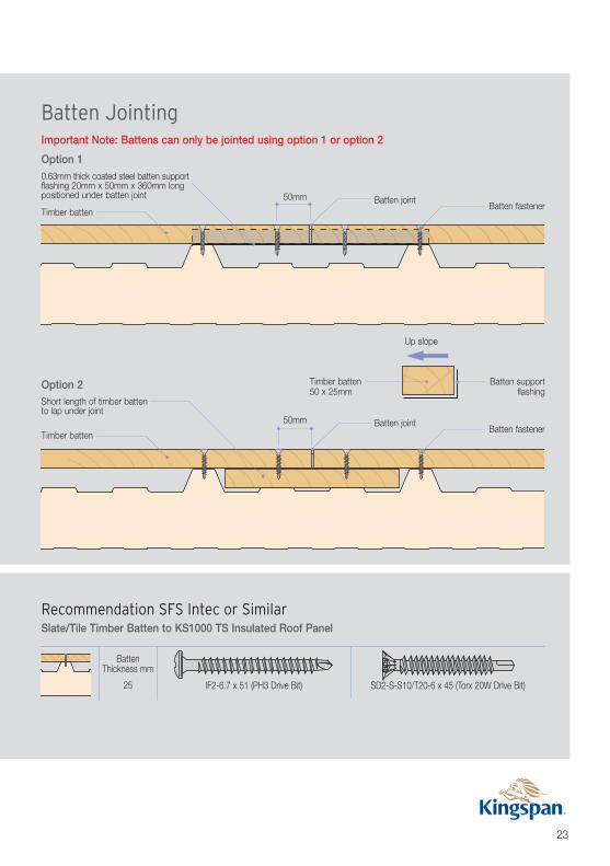
Important Note: Battens can only be jointed using option 1 or option 2
Option 1
Batten Jointing
0.63mm thick coated steel batten supportflashing 20mm x 50mm x 360mm longpositioned under batten joint
Timber batten
50mm Batten jointBatten fastener
Up slope
Timber batten50 x 25mm
Batten supportflashing
Option 2Short length of timber battento lap under joint
Timber batten
50mm Batten jointBatten fastener
Recommendation SFS Intec or SimilarSlate/Tile Timber Batten to KS1000 TS Insulated Roof Panel
BattenThickness mm
25 IF2-6.7 x 51 (PH3 Drive Bit) SD2-S-S10/T20-6 x 45 (Torx 20W Drive Bit)

24
Ridge Details
Verge Details
Typical Construction Details
Ventilated ridge slate/tile by others
Ridge batten
Air flow Air flow
uPVC profile filler unit
0.63mm thick coatedbatten support platefixed to external weathersheet with two fasteners
KS1000 TSinsulated roof panel
Air seal – 8mm Ø butyl rubber sealant
Internal ridge flashing with150mm overlap sealed with air
seal, Vapourflex or gun-grade sealant
Gun applied fire rated canisterinsulation, site applied
Roof slates/tiles includingbattens by others
Note: Project specific construction details must be used. Please refer to the Kingspan Design and Construction Guide for further information.
Fascia board by others
Roof tile system includingbattens by others
KS1000 TS insulated roof panel
Closure flashingwith 150mmsealed butt straps
PIR board insulation with site applied fire ratedcanister insulation to fill any gaps if required to
maintain continuity of insulation
Air seal – continuous bead of gun-grade sealant

25
Eaves Details
Roof slates/tiles laid to manufacturersrecommendations
KS1000 TS insulated roof panel
Kingspan Eaves Beam
Overhang varies
Drip flashing
Slate/tile battens by others
Insect mesh fixed to batten andturned under flashing
Gutter & bracketsby others
Timber facia by others
Timber soffit by others
Air seal –continuous band
of gun-gradesealant
Note: Project specific construction details must be used. Please refer to the Kingspan Design and Construction Guide for further information.
Air flow

26
Valley Gutter Details
Hip Valley Details
Typical Construction Details
Note: Project specific construction details must be used. Please refer to the Kingspan Design and Construction Guide for further information.
Roof slates/tiles including battens by others
KS1000 TS insulatedroof panel
Insect mesh
Air flow Air flow
Air seal – 8mm Ø butylrubber sealant
Air seal – 8mm Ø butylrubber sealant Non-thermally broken
factory made gutter withPIR insulation to 0.35 or0.25 U-value
KS1000 TS insulated roof panel
Air seal – 8mm Ø butylrubber sealant
Panel crowns cut back on site
Air seal – 8mm Ø butylrubber sealant
In-situ GRP weatheringby specialist contractor
Cleader angle bysteelwork contractor
Gun applied fire rated canister insulation,site applied as panel is placed
Roof slates/tiles includingbattens by others
Lead or similar valley hipgutter by others
Internal valley hip flashing with150mm laps with air seal –
vapourflex or gun-grade sealant
27
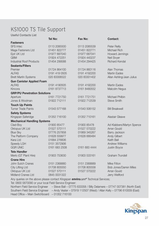
KS1000 TS Tile SupportUseful Contacts List
Tel No: Fax No: Contact:FastenersSFS Intec 0113 2085500 0113 2085539 Peter ReillyMage Fasteners Ltd 01451 822777 01451 822771 Michael RichEjot UK Ltd 01977 687040 01977 687041 Howard JenningsQBM 01924 472251 01924 440237 Neil SivyerIndustrial Roof Products 01454 299588 01454 294425 Richard KendalSealants/FillersPremier 01724 864100 01724 860116 Alan ThomasALFAS 0191 419 0505 0191 4192200 Martin EadesBrett Martin Systems 020 83306522 020 83301402 Allan Ashling/Jean JuliusGun Canister Applied FoamALFAS 0191 4190505 0191 4192200 Martin EadesKincora 0161 8737713 0161 8480552 Malcolm NegusGRP/PU Penetration SolutionsAperture 0161 7721750 0161 7721751 Michael PhilbinJones & Woolman 01922 712111 01922 712539 Steve SmithTouch Up PaintsTurner Trade Paints 01543 577168 01543 506152 Bill BreakwellSafety SystemsKingspan Saferidge 01352 716100 01352 710161 Alastair GleaveMechanical Handling SystemsClad-Boy 01900 85477 01900 85478 Ad Klabbers/Martyn SpenceOktopus UK Ltd 01527 570111 01527 570222 Arran GouldBlue Sky 07776 257858 01869 345267 Barry JacksonThe Platform Company 01628 559977 01628 666484 Andy GilbertKera Ltd 01684 276606 Keith BellSpeedy LGH 0151 3572906 Andrew WilliamsGGR UNIC 0161 683 2508 0161 683 4444 Justin BoyceTele HandlerMerlo (GT Plant Hire) 01903 753630 01903 533161 Graham TrundellCrane HireJohn Sutch Cranes 0151 2368880 0151 2368889 Mike FittonCity Lifting Ltd 01708 805550 01708 805558 Bob Jones/Darren MilesOktopus UK Ltd 01527 570111 01527 570222 Arran GouldMidland Cranes Ltd 0845 0031322 Jerry WellfordAny queries on the above please contact Kingspan envirocare® Technical Services;Tel: 0800 5870090 or your local Field Service Engineer:Northern Field Service Engineer – Steve Ball – 07775 633358 / Billy Delamere – 07747 007381 (North East)Southern Field Service Engineer – Andy Veater – 07919 112507 (West) / Allan Kelly – 07796 610009 (East)Head Office – Main Switchboard – 01352 716100

Kingspan LimitedUK: Telephone: +44 (0) 1352 716100 Fax: +44 (0) 1352 710161 Email: [email protected]
Ireland: Telephone: +353 (0) 42 96 98500 Fax: +353 (0) 42 96 98572 Email: [email protected]
Details for the following countries; Australia, Belgium, Czech Republic, France, Germany, Hungary, Netherlands, New Zealand, Norway, Poland, Romania, Slovakia & Sweden can be found by visiting our website www.kingspanpanels.com or our group website www.kingspan.com
Care has been taken to ensure that the contents of this publication are accurate, but Kingspan Limited and its subsidiary companies do not accept responsibilityfor errors or for information that is found to be misleading. Suggestions for, or description of, the end use or application of products or methods of working are for
information only and Kingspan Limited and its subsidiaries accept no liability in respect thereof.
KS1000 LPLo-Pitch
KS1000 TS Slate& Tile Support
KS500/1000 ZIPKingzip
®Standing
Seam
KS1000 RWTrapezoidal
KingspanEnergiPanel™
Kingspan Insulated Roof, Wall & Façade SystemsRoof Systems
KS1000 SFSecret Fix
KingspanRoof Tile
KS1000 FCBox Profile
KS1000 CRCurved Roof
KingspanEnvirodek™
KS1000Polycarb Rooflight
KS1000 FCBox Profile
KingspanEnergiPanel™
KS1000 RWTrapezoidal
Wall & Façade SystemsKS600, 900 &1000 MRMicro-Rib
KS600, 900& 1000Optimo™
KS600, 900& 1000 EBEuro-Box
KS600, 900& 1000 FLFlat
KS600, 900& 1000 FL-SStucco
KS600, 900 &1000 MM Mini-Micro
KingspanThermatile
KingspanThermabrick™
KingspanThermastone
KingspanWoodTherm™
KingspanRender Panel
KingspanWall-Lite
KS600, 900 &1000 CXConvex
KS600, 900 &1000 WV Wave
KS600, 900 & 1000 LSLongspan™
AncillariesGutters, Tophats & Flashings


