Download - Product Catalog Power Cable Accessories

Power Cable Accessories

2

3
Introduction 5
Terminations – Low and Medium Voltage 23
Connection Systems for Medium VoltageGas-insulated Switchgear 45
Joints – Low Voltage 55
Joints – Medium Voltage 75
Sealing Systems 97
Insulation Tubing and Repair Tape and Wraparounds 105
High Voltage Cable Accessories 115
Tools and Accessories 129
Con
tent

4
Intr
oduc
tion

5
Introduction
General 6
Technologies
Heat-shrink 10
Push-on 12
Pre-expanded 13
Resin 14
Gel 15
Material Properties
Electrical Stress Control 16
Weathering and Ageing Resistivity 17
Design Principles
Low Voltage Jointing System 18
Medium Voltage Jointing System 19
Medium Voltage Termination System 20
Medium Voltage Connection System 21
6
General
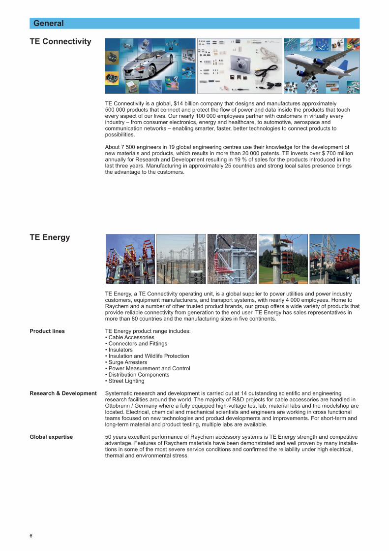
TE Energy, a TE Connectivity operating unit, is a global supplier to power utilities and power industrycustomers, equipment manufacturers, and transport systems, with nearly 4 000 employees. Home toRaychem and a number of other trusted product brands, our group offers a wide variety of products thatprovide reliable connectivity from generation to the end user. TE Energy has sales representatives inmore than 80 countries and the manufacturing sites in five continents.
TE Energy product range includes:• Cable Accessories• Connectors and Fittings• Insulators• Insulation and Wildlife Protection• Surge Arresters• Power Measurement and Control• Distribution Components• Street Lighting
Systematic research and development is carried out at 14 outstanding scientific and engineeringresearch facilities around the world. The majority of R&D projects for cable accessories are handled inOttobrunn / Germany where a fully equipped high-voltage test lab, material labs and the modelshop arelocated. Electrical, chemical and mechanical scientists and engineers are working in cross functionalteams focused on new technologies and product developments and improvements. For short-term andlong-term material and product testing, multiple labs are available.
50 years excellent performance of Raychem accessory systems is TE Energy strength and competitiveadvantage. Features of Raychem materials have been demonstrated and well proven by many installa-tions in some of the most severe service conditions and confirmed the reliability under high electrical,thermal and environmental stress.
TE Connectivity is a global, $14 billion company that designs and manufactures approximately 500 000 products that connect and protect the flow of power and data inside the products that touchevery aspect of our lives. Our nearly 100 000 employees partner with customers in virtually everyindustry – from consumer electronics, energy and healthcare, to automotive, aerospace andcommunication networks – enabling smarter, faster, better technologies to connect products topossibilities.
About 7 500 engineers in 19 global engineering centres use their knowledge for the development ofnew materials and products, which results in more than 20 000 patents. TE invests over $ 700 millionannually for Research and Development resulting in 19 % of sales for the products introduced in thelast three years. Manufacturing in approximately 25 countries and strong local sales presence bringsthe advantage to the customers.
Product lines
Research & Development
Global expertise
TE Connectivity
TE Energy

7
General
Raychem products, from TE Connectivity, are known for their high quality, reliability, and breadth of industry-leading electrical products that include cable accessories, insulators, surge arresters, andinsulation & animal protection products. However, to be your partner on the power grid, it takes morethan that. Raychem’s decades-long dedication to innovation, a desire to create products that endure,and a global network of dedicated TE Connectivity professionals willing to do what it takes to keep yourgrid operating efficiently is also at the core of who we are. Raychem products along with TEConnectivity’s ability to connect products to possibilities equal “your power grid partner”.
TE Energy offers a comprehensive range of Raychem cable accessories for nearly all cable types up to high voltage applications. The most innovative utilities and industries around the world, includingmining, marine, offshore and nuclear, use Raychem power cable accessories. Designed to withstandenvironmental extremes and high pollution levels over long operating lifetimes, our products maintainservice reliability in both overhead and underground installations.The product line includes indoor and outdoor terminations, inline, branch and transition joints as well as universal insulation, sealing and repair systems for use in the cable networks. Tailored for theapplications we offer different technologies such as heat-shrink, push-on, pre-expanded, resins andgels. Based on our experience in the materials and design of cable accessories we can provide a product, which can be easily installed and is perfectly adapted to the application in local cabletechnologies, network systems and installation processes.
TE Energy cable accessories are designed and tested to meet the international standards IEC,CENELEC and IEEE as well as the local specifications BS, CSN, GOST, MSZ, PN, STN, STR, VDEetc. as far as applicable.
The currently relevant international standards tested to are:EN 50393:2006 - Test methods and requirements for accessories for use on distribution cables
of rated voltage 0,6/1,0 (1,2) kV.HD629.1.S2:2006 - Test requirements on accessories for use on power cables of rated voltages
from 3,6/6 (7,2) kV up to 20,8/36 (42) kV.Part 1: Cables with extruded insulation.
HD629.2.S2:2006 - Test requirements on accessories for use on power cables of rated voltages from 3,6/6 (7,2) kV up to 20,8/36 (42) kV.Part 2: Cables with impregnated paper insulation.
EN 61442:2006 - Test methods for accessories for power cables with rated voltages from 6 kV (Um = 7,2 kV) up to 36 kV (Um = 42 kV).
UO/U (Um) as referred to in IEC and CENELEC standards:UO is the rated power-frequency voltage between phase conductor and earth or metallic screen for which the cable accessory is designed,U is the rated power-frequency voltage between phase conductors for which the cable accessory isdesigned,Um is the maximum value of the ‘highest system voltage’ for which the cable accessory may be used.
To cover all typical voltages in distribution networks, TE Energy tests cable accessories to the highestsets of rated voltages: 3,8/6,6 (7,2) kV; 6,35/11 (12) kV; 8,7/15 (17,5) kV; 12,7/22 (24) kV; 19/33 (36) kV; 20,8/38,5 (42) kV and higher voltages.
Raychemcable accessories
Cable accessories in different technologies
Test and qualification
Voltage definition
Voltage ranges

8
General
Even the best technology can be applied in a wrong way. To avoid such situations, TE has establisheda technical support service to provide technical information and application guidelines for its customers,such as cable fitters, project and maintenance engineers, constructors, equipment manufacturers aswell as specification and purchasing engineers.
A sound and practice oriented range of customer support is provided:- presentations and seminars,- technical papers focusing on new industry trends and products,- training in cable preparation, installation techniques and product selection for engineers and
installers,- practical demonstrations and field installations,- individual solutions to specific customer’s problems.
CustomerSupport
Seminars, Trainings
No special tools are required for the cable preparation. The installation of the Raychem cableaccessory is easy and independent from the used technology. The Raychem accessories can be putinto operation immediately after their installation. The cable accessory is supplied in a kit with allnecessary components including installation instruction in a local language.For instance, upon delivery of a heat-shrink accessory kit all individual parts are stretched such far thatthey can be easily slid over the prepared cable end. They shrink, when sufficiently heated, and firmlyenclose the cable and protect it against moisture, while the adhesive melts and fills all grooves andvoids. Raychem heat-shrink cable accessories are constructed in a similar way to the cablesthemselves and can, like these, be bent in narrow spaces.Terminations are designed for simple upside-down installations by turning the heat-shrinkable sheds.
Installation

9
General
TE Energy with its manufacturing sites around the world produces to global requirements and globalmanufacturing systems. TE Energy sites combine economical and in-time manufacturing with highquality products.
To improve the availability of products TE Energy continuously monitor delivery performance and leadtimes, look for opportunities to shorten cycle times and enhance services. This constant worked onprocess is directed towards our goal: complete customer satisfaction.
All Raychem cable accessory kits contain the necessary components for the installation like electricalinsulation materials, installation instructions and a bill of material. The mechanical cable lugs and theconnectors are included in the kits unless otherwise stated, solderless earth connections are eitherincluded in the kits or can be ordered separately.
Manufacturingand Logistics
Global manufacturing and Efficiency
Availability
Kit content
The quality standards of all materials throughout the entire manufacturing process beginning with theraw materials and continuing through to the packaged product are continuously monitored anddocumented. Materials as well as complete Raychem accessories are regularly re-qualified. As a resultof our well established Quality Management System including quality assurance, TE Energycontinuously achieves re-certification according to ISO 9001 and also to ISO 14001.
TE is committed to compliance with all applicable environmental, health and safety laws also to theprotection of our employees and the environment. These efforts have been driven by directives as the“Restriction of Hazardous Substances” (RoHS) and “Registration, Evaluation and Authorization ofChemicals” (REACH), which requires the substantial elimination of lead, cadmium, hexavalentchromium, brominated flame retardants and mercury from the products. We have been one of the firstcompanies which implement the RoHS and the REACH directives into the manufacturing process.
The usage of only ecologically sound and recyclable components, the continuously reduction ofpackaging materials and saving energy are other initiatives to support the effort of environmentalprotection.
Quality Standards,Environment,Health and Safety
ISO 9001, ISO 14001
RoHS, REACH
Reduction of packagingmaterial
10
Technologies
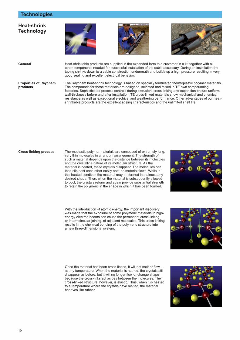
Heat-shrinkable products are supplied in the expanded form to a customer in a kit together with allother components needed for successful installation of the cable accessory. During an installation thetubing shrinks down to a cable construction underneath and builds up a high pressure resulting in verygood sealing and excellent electrical behavior.
The Raychem heat-shrink technology is based on specially formulated thermoplastic polymer materials.The compounds for these materials are designed, selected and mixed in TE own compoundingfactories. Sophisticated process controls during extrusion, cross-linking and expansion ensure uniformwall-thickness before and after installation. TE cross-linked materials show mechanical and chemicalresistance as well as exceptional electrical and weathering performance. Other advantages of our heat-shrinkable products are the excellent ageing characteristics and the unlimited shelf life.
Heat-shrinkTechnology
General
Properties of Raychemproducts
Thermoplastic polymer materials are composed of extremely long,very thin molecules in a random arrangement. The strength ofsuch a material depends upon the distance between its moleculesand the crystalline nature of its molecular structure. As thematerial is heated, these crystals disappear. The molecules canthen slip past each other easily and the material flows. While inthis heated condition the material may be formed into almost anydesired shape. Then, when the material is subsequently allowedto cool, the crystals reform and again provide substantial strengthto retain the polymeric in the shape in which it has been formed.
With the introduction of atomic energy, the important discoverywas made that the exposure of some polymeric materials to high-energy electron beams can cause the permanent cross-linking, or intermolecular joining, of adjacent molecules. This cross-linkingresults in the chemical bonding of the polymeric structure into a new three-dimensional system.
Once the material has been cross-linked, it will not melt or flow at any temperature. When the material is heated, the crystals stilldisappear as before, but it will no longer flow or change shapebecause the cross-links act as ties between the molecules. Thecross-linked structure, however, is elastic. Thus, when it is heatedto a temperature where the crystals have melted, the materialbehaves like rubber.
Cross-linking process

11
Cross-linking by electron-beam was pioneered by Raychem andis still the most commonly employed method. Other methods arecross-linking with a radioactive source like Cobalt or withchemicals. Not being properly controlled they could cause harmfor people, environment and material based on the aggressiveingredients which are responsible for the cross-linking process.
Cross-linking with electron-beam
Technologies
Beaming the tubing causes permanent cross-linking of adjacentmolecules. The graphic is an enlarged schematic view of a verysmall cross-linked section of extremely long molecules and anend view of a piece of heat-shrinkable tubing.
Once the tubing has been cross-linked, the next step in impartingshape memory is to heat the compound above its crystallinemelting point. The molecules are then tied together only by thecross-links.
While hot, the tubing is deformed by applying pressure, thusstretching the cross-linked molecule.Long-term experience in process know-how is required to avoideccentricity and longitudinal shrinkage of the tubing.
While in this deformed position, the tubing is cooled; the crystalsthen reappear, thereby locking the structure together in thisdeformed condition indefinitely. This is the form in which tubing issupplied to customers and can be stored without shelf lifelimitations.
During installation the tubing is heated, melting the crystals. Thecross-links allow the material to return to its original shape.
After cooling, the crystals reform and the tubing is locked in itsrecovered form.
Expansion process
Shrinking process

12
Technologies
Products of this technology are stored and supplied unexpanded. These products are pushed on a prepared cable during their installation. Sometimes special tools might be required for this action.Being pushed and installed materials stay expanded. Different silicones and more rigid EPDM areemployed for push-on technology. The more flexible material is used, the installation becomes easierand the application range becomes wider. Materials used for this technology are susceptible formechanical damage.
The art combining high flexibility with split & tear and weathering performance were utilized in TEEnergy push-on materials. TE Energy produces push-on cable accessories of a cross-linked, highly-flexible silicone body, which ensures easy and tool-free installation. Raychem products are designed to ensure no slippage from the cable during the all operation conditions. The accessories haveexceptional electrical and weathering performance and they are resistant to UV-light, contamination,track and erosion.
Raychem push-on cable accessories have the unlimited shelf life and do not required any special toolsfor their installation, which should be performed at ambient temperature above 0 °C. The accessorybody is pushed onto the prepared cable up to the correct position and builds up a high pressure for a reliable sealing, stable positioning and of course excellent electrical behavior after the installation.
Push-on
General
Properties of Raychemproducts

13
Technologies
Pre-expanded technology is similar to the push-on technology with the difference that the elastomericbody is pre-expanded on a holdout. Due to the required higher expansion rates more flexible materialswith high tear resistance are needed. Silicone materials with different softness and the more rigidEPDM are used for pre-expanded technology.
All materials exhibit tension set (less shrinkage behavior) over time, which limits the application rangeand the storage time. To ensure sufficient pressure for electrical and mechanical sealing purposes, thetension set must be considered when the application range is defined.
The cross-linked, high flexible silicone body is expanded on a robust holdout, which prevents theproducts from premature deform and collapse. Long-term performance of this type of cable accessorydepends on its correct positioning, which is easily controllable and adjustable during the installationwithin TE products. The installation itself should be performed at ambient temperature above 0 °C.Raychem accessories are designed to be used with mechanical connectors and lugs and are adaptedfor all commonly employed cable screens. The accessories have exceptional electrical and weatheringperformance and they are resistant to UV-light, contamination, track and erosion. Raychem pre-expanded cable accessories have a shelf life of 24 months after manufacturing.
Pre-expanded
General
Properties of Raychemproducts

14
Technologies
Filling materials consist of two resin components supplied separately from each other e.g. in bags orcans. During an installation the components are mixed together and poured into joint’s housing forcuring.Polyurethane or epoxy materials, emerge by cross-linking of a resin with a reactive isocyanate orpolyamine hardener, were very often used in the past. The exothermal hardening process producesheat and the materials could be dangerous and hazardous for the health and the environment due toincluded isocyanates or bisphenols. After cross-linking most mixtures become a solid plastic material.
To reduce a heath risk and allow installations at low temperatures TE Energy has developed theGUROFLEX casting material consisting of 2 isocynate-free resin components. Upon mixing the twocomponents are cross-linked with each other by a non-exothermal process. Cross-linked GUROFLEXresin adheres to nearly all cable materials and stays elastic.The material exhibits excellent insulation properties and also accommodates thermal expansions ofinsulated cables. GUROFLEX resin covers and adheres to metal components, protects them fromcorrosion and is re-enterable after the installation.
The installation of GUROFLEX resin is possible at the temperatures as low as -10 °C and in service it is resistant to the temperatures below -20 °C.
GUROFLEX resin is easy to handle because it is not subject to any safety classification during use,transportation or disposal. The material is environmentally friendly, non-toxic and non-hazardous buthas, like all other resin materials, a shelf life of 24 months after manufacturing.
Resin
General
Properties of TE EnergyGUROFLEX material
Resin A
Resin B
Cross-linking
A
A
A
A
B
B
B
B
GUROFLEX non-exothermalcross-linking

15
Technologies
Gel technology is used in low voltage applications. The housing of supplied accessory is filled with thegel already from a factory. The cable connection area is positioned in the middle of the opened jointhousing and slightly pressed into the gel together with appropriate connectors. The installation iscompleted by closing of the housing. The installed accessory can be put immediately into the service.
Raychem PowerGel is especially developed for electrical applications from -40 °C to +90 °C continuoustemperature. PowerGel consists of silicone oil embedded in a cross-linked silicone matrix, whichcombines the advantages of solid (elastic memory) and liquid (wetting and confirming to a surface)sealing materials.
Gel
General
Properties of RaychemPowerGel
Force
Gel
Surface
Moisture
Excellent insulation properties, thermal and UV stability also halogen-freeness are features of RaychemPowerGel just like the unlimited shelf life, the excellent dielectric properties and the extremely highelongation and elasticity. Raychem accessories using PowerGel are suitable for polymeric cables inindoor or outdoor applications with possibility of underground, direct buried or immersion in water.
Raychem PowerGel displaces possible moisture, wets and prevents the metal surface from corrosionby applying a thin layer of silicone oil on it.
Moisture displacing

16
Material Properties
Electrical stress control in cable accessories
������
������ ��� �� �� ���
���
����
���
��
���
���
��
� �
��� ��� ��� ��� ��� �� �����
���
core insulationinsulationscreen
stresscontrollayer
A - without stress controlB - stress control coating
A - improper impedanceB - stress control tubingC - insufficient length of
the tubing
insulation screen core insulation
Uncontrolled electrical field at the end of the cable
Technology of non-linear stress control material
Technology of semi-conductive stress control material
Electrical field with a stress control system (tubing or coating)
The outer conductive layer of the cable is removed atthe cable’s end and forms a sharp edge resulting in a high electrical stress indicated by the narrowequipotential lines. If this area is not treated with an effective stress control system then it will lead toelectrical discharges with material ageing. Also voidsinside or in between insulating materials can causesuch discharges. These “partial” discharges cause a failure of the dielectric well before its intendedservice life has been reached. In addition, the stress at the screen end is high enough that even thesmallest notch can cause a breakdown.
Raychem medium voltage cable accessories includestress control coatings or tubing with a carefullycontrolled volume resistivity and permittivity to smoothout the high stress. The electrical field strength at theend of the screen cut is reduced to a level well belowthe upper limit for long term operation.This slim stress control system can be used on a variety of cable types, including paper cables, andaccommodates variations of cable dimensions.
The non-linear impedance of the stress control tubingavoids an increase of the amplitude. The stress isdistributed over a longer control area (B). This is basedon the interaction between the resistive components ofthe applied coating and the capacity of the cableinsulation. By an improper selection of the materialsthe impedance would lead to an unacceptable steepvoltage rise at the screen end (A). Reducing the lengthor wrong positioning results in discharge at the tubingend (C). All Raychem cable accessories take theseeffects into account.
The stress control base material is enriched with zincoxide (ZnO) and it has insulating characteristics up to a specific voltage. The material behaves similar to a varistor and becomes conductive if the field strengthis higher than a certain switching point. The resultingvoltage distribution allows a short termination lengthwhile the electrical stress at the screen end area iskept low. Higher voltage load does not result in higheramplitude of the electrical field strength but only thecontrol area will become longer.

17
Material Properties
Weathering and ageing resistivity
insulation screen
void filler
two layers ofjoint insulation joint insulation screen patch
stress controltubing
coreinsulation connector
The stress control tubing contacts and overlaps the screen at each end of the joint and controls thestress at these areas in the same way as in terminations. Together with the high permittivity yellow voidfiller, the stress control tubing distributes the equipotentials thus reducing the electrical stresses at theend of the connector. The two layers of insulation bonded to the outer conductive layer have a thicknessdesigned to the rated voltage of the joint and prevents any interfacial discharge. The stress controlsystem and the selected materials of this joint makes it unnecessary to chamfer the cable insulation or to use a connector with specially profiled shape.
Stress distribution insideRaychem joint
The performance of Raychem cable accessories is the result of the interaction between materialformulations, product design, the manufacturing process and correct selection for the application. The excellent behaviour of Raychem insulation materials for low, medium and high voltage cableaccessories is achieved by the special formulation adapted to product and application. Chemical components included in the material work as fire extinguisher and avoid the building oftracking. Raychem materials for outdoor applications resist weathering processes like contamination,UV-light, dust and have long time stability even in the most severe environments.
To evaluate the lifetime performance of different materials and designs TE Energy regularly performlisted tests:- Tracking and Erosion Resistance Test (TERT) according to IEC 60587- Humidity Test according to IEC 61442- Salt fog Test according to IEC 61109- UV resistance test according to ISO 4892
The Tracking and Erosion Resistance Test (TERT) show the appearance of tracking or erosion onmaterial samples by periodically increased contamination and voltage. In the other tests the completeproducts are stressed with humidity, salt fog or intensive UV light and tested afterwards.
Tracking or erosion can occur when leakage currents are developed in wet conditions on contaminatedmaterial. Under certain environmental conditions, these leakage currents can deteriorate the surface ofthe outer material by building tracking paths or by erosion. Both would finally lead to a failure of theproduct by breakdown, in which tracking is a fast process (minutes) and erosion is a slow process(years).
Properties
Testing
Tracking and Erosion
voltage
earth
voltage
earth
voltage
earth
voltage
earth
voltage
earth
voltage
earth
voltage
earth
voltage
earth
Film ofconductivewater
Evaporationcaused bythe leakagecurrent
Dry zone
Blackconductivepathof carbon
Dry zone
Trackingpath
Arcingbridging thedry zone
Tracking path Longtrackingpath
Breakdown
voltage
earth
Arcing whichdegradesthe surfaceand forms aconductivepath (carbon)
The graphics describe the appearance of tracking. The appearance of erosion is similar but instead of a path the erosion reduces the material.

18
Design Principles
Raychem Low Voltage Jointing System
The joint is complete and can be put into operation immediately.
The Raychem low voltage jointing system for mechanical or crimp connectors is widely used and acknowledged as a highlydependable and easy-to-install jointing method for 3- and 4-core paper cables and also for 4- and 5- core polymeric insulated cabletypes.
The principle of the construction and the simple way of installation are described on a joint for 0,6/1,0 (1,2) kV polymeric insulatedcables.
Construction
1 Outer tubing: Thick-wall protectionagainst mechanical stresses andagainst moisture by sealing onto theoversheath.
2 Inner tubing: Thick wall tubingproviding electrical insulation andprotection of the connection areaagainst moisture inside the cable.
3 Hot-melt adhesive: Perform a durableand repeatable sealing.
1 3
3 2
The cable ends are prepared according to the installation instruction, the smaller innertubing and the outer tubing are slipped over the cores and the conductors areconnected with mechanical or crimp connectors.All joints are designed to allow crossing of the cable cores.
The inner tubing are positioned over the connectors and shrunk down. They fit tightlyand the wall thickness is adapted to the core insulation even over bulky mechanicalconnectors. The adhesive in the pre-coated tubing seals out moisture and corrosion andconfirms to the thermal expansion of the cable.
The mechanical and sealing functions of the oversheath are assured by a thick-walltubing positioned over the jointing area and shrunk. A durable and repeatable seal isproduced by means of a hot-melt adhesive pre-applied to the entire length of the tubing.
Joints for paper insulated cables with steel tape armour have a similar design as jointsfor polymeric insulated cables. The kits include additional solderless earth connectionsfor the lead sheaths and a neutral connection system if required.
Installation

1 2 3 b) recovered
19
Design Principles
Raychem Medium Voltage Jointing System
The design of a single-core joint for a polymeric insulated cable is described here. The same design principles are used for 3-corecables. For transition joints, special oil barrier tubing are used to transform a draining oil (MI) as well as non draining oil (MIND) paperinsulated cable into a quasi polymeric insulated cable with a radial field.
1. Electrical stress controlThe stress control tubing and the patch have a precisely defined impedance characteristic whichsmoothes the electrical field over the connector and cable screen ends. During the installation of 12 kVand 24 kV joints, the special void filling yellow tape will be compressed by the two stress control tubing.The patch over the connector will be compressed by the high shrink force of the triple extruded jointbody. For the design of a 42 kV joint only the special yellow void filling tape is used, which iscompressed by one stress control tubing. It is not necessary to chamber the cable insulation or to use a connector with specially profiled shape.
2. Insulation and screenThe triple extruded joint body provides the correct thickness of insulation (red) in one installation step.The insulation screen is provided by the outer wall of the tubing, which is of heat-shrinkable conductivepolymer (black). This technique saves installation time and ensures a flawless bond between jointinsulation and screen, even up to 42 kV.
3. Metallic shieldingCopper mesh and roll springs ensure the correct screen connection across the joint area and makeelectrical contact with the outer screen of the joint. The design passed tests up to 11 kA short circuitand up to 400 A currents simulating ground fault situation.
4. Outer sealing and protectionThe heat used to shrink the outer tubing causes the pre-coated adhesive to melt and flow, resulting in a lasting moisture and corrosion barrier on the cable oversheath. The outer tubing provides mechanicalimpact and chemical resistance as expected from cable oversheaths. For armoured cables, Raychemjoints incorporate either a quick to install galvanised steel joint case or steel tape or fibre glassreinforced heat-shrink wraparound.
The elastomeric joint component and the outer sealing tubing are slid over the prepared cable end. Thescreen ends are electrically smoothed with void filling compound and stress control tubing are shrunkover the cable ends. By simply tightening the bolts of the mechanical connector, the conductors arejointed and then covered with a stress control patch. The elastomeric component is quickly shrunk overthe connection area. Roll springs and copper mesh rebuild the cable shield and the oversheath isreplaced by an adhesive-coated sealing tubing. All kits are supplied with illustrated step by stepinstructions.
The triple extruded joint body, supplied in an expanded form, consists of 3 bonded layers, see picture a)below. The two heat-shrinkable outer layers (1. black conductive, 2. red insulating) hold the innerelastomeric layer (3. red insulating) at full diameter. Application of the heat causes the outer layers toshrink, allowing the elastomeric, insulating layer to contract at the same time and closely fit on thejointing cable. Elastomers typically experience a reduction of the contraction force after storage and atcold temperatures. By applying heat this effect is overcome thus allowing an unlimited storage time andinstallations at low temperatures. The rubber-like characteristics of the insulation material combinedwith the rigid outer heat-shrinkable wall enable the joint to follow the thermally induced dimensionalchanges of the cable insulation.
Product design
Installation procedure
Triple extruded elastomeric technology
1 2 3 4
a) expanded

20
Design Principles
Raychem Medium Voltage Termination System
Raychem accessories provide a universal system of indoor and outdoor terminations for paper or polymeric insulated cables, for singleor three core cables, for cables with round or sector shaped conductors and most types of screening or armouring.The termination's materials possess exceptional resistance to prolonged electrical stress and weathering, but are also capable of beingshrunk down quickly to fit and seal a cable.
The typical modules of a modern medium voltage termination:
1. Moisture sealingDurable sealing is achieved by special Raychem sealants on the inside of non-tracking, weather-resistant components. By applying heat on the components, the shrinking action of the tubing causesthe hot-melt sealant to flow into place.In case of three core cables, a sealant-lined heat-shrinkable breakout installed over the cores andcable crutch provides a sealed and weather-resistant surface from the terminating lugs to the cableoversheath.
2. Compact and versatile stress controlTo meet the need for space-saving, flexible termination design, adaptable to different types of compactequipment, TE Energy has developed a material with carefully controlled non-linear impedance basedon ceramic semiconductor technology (ZnO), applied as coating inside the tubing. The stress controlcoating is softened by the applied heat and conforms and bonds to even irregular insulation surfaces toensure a void free contact.
3. Non-tracking insulation tubingThe superior non-tracking characteristics and long-term erosion resistance of Raychem terminationshave been exhaustively demonstrated in comparative tests at major independent laboratories and TEEnergy’s own extensive development facilities. These results are borne out by the continuingperformance of over a million units installed in tropical, desert, arctic and industrially polluted climates,confirming that Raychem terminations do not track even in severe service conditions and verifying theirexceptional erosion resistance and reliability.
4 . Stress grading void filler The void filler is easily applied in form of a short adhesive tape. It ensures that, independent of the typeof semi-conductive screen or removal method, no air voids can cause discharges in the high stressarea of the screen end.
5. EarthingEarthing wires or braids are imbedded in the sealing mastic to prevent any corrosion by moistureingress. For cables with tape screen or metal sheaths with armour solderless earthing systems areeither provided within the termination kit or can be ordered separately.
Product design
5
4
3
2
1
1

21
Design Principles
Raychem Medium Voltage Connection System
The Raychem connection systems fulfil all major requirements for MV gas-insulated switchgears and transformers used in modernsubstations and industry facilities. With several decades of experience in the field, the systems are watertight and guaranteeuninterrupted operation, even under extreme operation conditions with severe pollution. TE Energy is able to supply a connectionsystem for different voltages, rated currents, for cables with either paper or polymeric insulation and for outer cones as well as for theinner-cone bushing system.
In the most cases switchgears of varied suppliers and some transformers are connectedinto the network through the outer cone bushing profile according to CENELEC HD506S1, EN 50180 and EN 50181 type C1 or C2 (630 A or 1250 A), type B (400 A) andtype A (250 A).Only few primary types of switchgear in the market are equipped with inner conebushings.
Bushing types
EN 50181 bushing type A (250 A)
The RSES-52xx and RSSS 52xxscreened connection systems with 250 Acurrent-carrying capacity is a push-ontermination for polymeric insulatedcables, designed for the connectionbetween the switchgear and thetransformer.
EN 50181 bushing type B (400 A)
The RSES-64xx screened separableelbow connection system with mechanicallugs are designed to connect 1- and 3-corepolymeric cables to medium voltage gasinsulated switchgear and other equipmentusing bushing type B, specified for 400 A,up to 42 kV.
EN 50181 bushing type C1 (630 A) or C2 (1250 A)
The RICS and RCAB insulating adaptersdesigned for bushing of both C types arecompatible with all Raychem terminationsand can thus be used to connect any typeof cable up to 24 kV, irrespective ofwhether it is paper or polymeric insulatedor has one or three cores.
The RSTI screened connection system isdesigned to connect single- and three-core polymeric insulated cables on toswitchgear’s bushing of both ratings C1and C2 up to 42 kV.
All dimensions in mm
* = 22 for type C1= 32 for type C2
Ø70 M16 Ø* Ø46 Ø56
29
9012
Ø70 Ø14 Ø46 Ø56
9012
Ø48,5 Ø7,9 Ø30,9 Ø32,5 Ø44,5
10 48
22
Term
inat
ions

23
Terminations – Low and Medium Voltage
Terminations for polymeric insulated cables 1 kV 24
Terminations for belted, paper insulated cables (MI and MIND) with one common metal sheath 6 kV and 10 kV 26
Terminations for screened, paper insulated cables (MIND) with one metal sheath per phase 10 kV, 20 kV and 35 kV 28
Indoor terminations for screened, paper insulated cables (MI) with one metal sheath per phase 10 kV and 20 kV 30
Terminations for flexible, screened, rubber insulated cables 6 kV 32
Terminations for unscreened, 3-core polymeric insulatedcables 6 kV and 10 kV 34
Terminations for screened, 3-core polymeric insulated cables 10 kV, 20 kV and 35 kV 36
Terminations for screened, 1-core polymeric insulated cables 10 kV, 20 kV and 35 kV 38
Elastomeric terminations with integrated stress control for screened, 1-core polymeric insulated cables with wire screen 10 kV, 20 kV and 35 kV 40
Terminations for screened, polymeric insulated filter cables up to 150 kV D.C. 42
Terminations for screened, polymeric insulated cablesfor electrified Railway systems 25 kV A.C. 43

24
Terminations for polymeric insulated cables 1 kV
CableThe terminations are designed for 3-, 4- and 5-core polymeric insulatedcables with or without armour.For example: AYKY, CYKY, N(A)YC(W)Y,NA2X2Y, E-A2X2Y.
Dimensions L2, L3 see table on the nextpage; L1 depends on the requirement of a relevant installation
��
��
��
Design of terminations The cable crutch is sealed by an adhesivelined heat-shrinkable breakout, which isinstalled over the cores and the end of theoversheath. Heat-shrinkable tubing sealbetween the cable lug and the end of thecore insulation. For single core cablesonly a lug sealing tubing is needed. Allmaterials are resistant to UV-light andweathering.
L1
L2
L3
A solderless earth connection systemconsisting of a roll spring and an earthbraid is included in terminations forarmoured cables. In case UV-light protection of the coreinsulation is required, the EN-CGPTinsulating tubing can be orderedseparately. All terminations can beordered as complete kits or ascomponents.Kits with the modification code -L12include mechanical lugs with a busbarconnection hole for M12 connection bolts.

25
Complete terminations for polymeric insulated cables including mechanical lugs
Cross section Ordering description Dimensions (mm)(mm2) cables without armour cables with tape armour L3 L2
3- and 4-core polymeric insulated cables25 - 70 EPKT-0031-L12 EPKT-0031-L12-CEE01 165 10050 - 150 EPKT-0047-L12 EPKT-0047-L12-CEE01 215 100
120 - 240 EPKT-0063-L12 EPKT-0063-L12-CEE01 220 150
5-core polymeric insulated cables35 - 70 POLT-01/5X 35- 70-L12 POLT-01/5X 35- 70-L12-CEE01 165 10070 - 120 POLT-01/5X 70-120-L12 POLT-01/5X 70-120-L12-CEE01 215 100
150 - 240 POLT-01/5X150-240-L12 POLT-01/5X150-240-L12-CEE01 220 150
Note: For 3-core cables the concentric neutral wires are sealed with sealing tape S1052-1-500 (length needed per terminationapproximately 50 mm) and insulated with MWTM tubing. Sealing tape S1052 and MWTM tubing have to be ordered separately.
Complete terminations for polymeric insulated cables without lugs
Cross section Ordering description Dimensions (mm)(mm2) cables without armour cables with tape armour L3 L2
3- and 4-core polymeric insulated cables4 - 35 EPKT-0015 EPKT-0015-CEE01 95 50
25 - 70 EPKT-0031 EPKT-0031-CEE01 165 10070 - 150 EPKT-0047 EPKT-0047-CEE01 215 100
150 - 400 EPKT-0063 EPKT-0063-CEE01 220 150
5-core polymeric insulated cables10 - 35 POLT-01/5X 10- 35* POLT-01/5X 10- 35-CEE01* 95 5035 - 70 POLT-01/5X 35- 70 POLT-01/5X 35- 70-CEE01 165 10070 - 120 POLT-01/5X 70-120 POLT-01/5X 70-120-CEE01 215 100
150 - 240 POLT-01/5X150-240 POLT-01/5X150-240-CEE01 220 150
* Kit include 4-core breakout; other kits include 5-core breakout.Note: For 3-core cables the concentric neutral wires are sealed with sealing tape S1052-1-500 (length needed per terminationapproximately 50 mm) and insulated with MWTM tubing. Sealing tape S1052 and MWTM tubing have to be ordered separately.
Breakout and tubing components for polymeric cable terminations
Cross section Ordering description Cross section Ordering description Dimensions (mm)(mm2) Breakout Insulating tubing* (mm2) Lug sealing tubing L3 L2
4-core polymeric insulated cables1,5 - 10 502S013/S EN-CGPT 9/ 3-0 1,5 - 10 MWTM-10/ 3- 50/S 60 50
4 - 35 502K033/S EN-CGPT 12/ 4-0 4 - 35 MWTM-16/ 5- 50/S 95 5025 - 95 502K046/S EN-CGPT 18/ 6-0 25 - 70 MWTM-25/ 8-100/S 165 10050 - 150 502K016/S EN-CGPT 24/ 8-0 70 - 150 MWTM-35/12-100/S 215 100
120 - 400 502K026/S EN-CGPT 39/13-0 150 - 400 MWTM-50/16-150/S 220 150
5-core polymeric insulated cables35 - 95 603W035/S EN-CGPT-18/ 6-0 25 - 70 MWTM-25/ 8-100/S 180 10050 - 150 603W040/S EN-CGPT-24/ 8-0 70 - 150 MWTM-35/12-100/S 180 100
120 - 240 603W040-R01/S EN-CGPT-39/13-0 150 - 240 MWTM-50/16-150/S 180 150
* For outdoor terminations the cores can be protected against weathering and UV-light with the insulating tubing EN-CGPT. Tubing lengths depend on the local installation requirements, technical and ordering details of MWTM and EN-CGPT tubing see thechapter “Insulation tubing and repair tape”. For single core cables only a lug sealing tubing is needed.
Terminations and components for other cable types are available on request.
Terminations for polymeric insulated cables 1 kV

26
Indoor terminations for belted, paper insulated cables (MI and MIND) with onecommon metal sheath 6 kV and 10 kV
CableThe indoor termination is designed for6 kV and 10 kV three core belted, paperinsulated (MI, MIND) cables.For example: SB, ASB, SAAB, AABY,ASBY, ААБУ, АСБУ, СБ2лГ, АСБ2лГ,СБнГ, АСБнГ, АивВГ, ПвПГ, Kny, KnFtly,AknFtA, AknFty, ANKOP, ANKOPV,CNKOY, CNKODY, IPO 13, IPO 14, NPO13, NPO 14, N(A)KBA, N(A)KLEY
Design of terminationThe paper cores are covered with oilbarrier tubing. The crutch is filled with an oil resistive yellow mastic and is sealed
Termination for MI and MIND cablesNominal voltage Cross section Ordering description DimensionUo/U (kV) (mm2) with cable lug* without cable lug** L (mm)
GUST-12/ 25- 50/ 450-L12 GUST-12/ 25- 50/ 450 45025– 50 GUST-12/ 25- 50/ 800-L12 GUST-12/ 25- 50/ 800 800
GUST-12/ 25- 50/1200-L12 GUST-12/ 25- 50/1200 1200
3,5/6 GUST-12/ 70-120/ 450-L12 GUST-12/ 70-120/ 450 450and 70–120 GUST-12/ 70-120/ 800-L12 GUST-12/ 70-120/ 800 8006/10 GUST-12/ 70-120/1200-L12 GUST-12/ 70-120/1200 1200
GUST-12/150-240/ 450-L12 GUST-12/150-240/ 450 450150–240 GUST-12/150-240/ 800-L12 GUST-12/150-240/ 800 800
GUST-12/150-240/1200-L12 GUST-12/150-240/1200 1200
* For terminations with mechanical lugs for M16 bolts use modification code -L16 (not available for kits with cross section 25–50 mm2).** Longitudinally sealed cable lugs are not part of the kit and can be ordered separately.Note: One termination kit includes material for 3 phases. The core lengths can be reduced to the requirements at the place of installation, the minimum core length is 450 mm.
Termination only for MI cablesNominal voltage Cross section Ordering description by length Dimension Solderless earthUo/U (kV) (mm2) L = 550 mm L = 900 mm D (mm) connection
16– 35 EPKT-4541 EPKT-4543 101 EAKT-1668-DE01
3,5/650–120 EPKT-4547 EPKT-4549 101 EAKT-1669-DE01
150–240 EPKT-4559 EPKT-4561 125 EAKT-1670-DE01300–400 EPKT-4565 EPKT-4567 125 EAKT-1671-DE01
16– 35 EPKT-4541 EPKT-4543 101 EAKT-1668-DE01
6/1050– 95 EPKT-4547 EPKT-4549 101 EAKT-1669-DE01
120–185 EPKT-4559 EPKT-4561 125 EAKT-1670-DE01240–300 EPKT-4565 EPKT-4567 125 EAKT-1671-DE01
Note: Longitudinally sealed cable lugs are not part of the kit and can be ordered separately. The core lengths can be reduced to therequirements at the place of installation, the minimum core length is 550 mm. Solderless earth connection must be ordered separately,it consists of 2 roll springs, earth lead, protection tubing and sealing adhesive.
with an adhesive lined, conductive break -out which is installed over the cores andthe end of the metal sheath. Yellow stresscontrol mastic is laid around the ends ofbreakout fingers and the cores are coveredwith red, non-tracking tubing. The end ofthe termination is sealed either to thecable lug or to the solid conductor with a sealing boot. The kit includes a solderlessearth connection. Kits with the modifica -tion code -L12 include mechanical lugswith a busbar connection hole for M12connection bolts, with code -L16 for M16bolts (note: M16 not available for kits withcross section 25–50 mm2).
Design of oil filled terminationsfor MI cablesThe cores are covered with brown,pressure-resistant oil-barrier tubing. A transparent oil pot with heat-shrinkablemoulded parts seals onto the oil barriertubing and the metal sheath. The pothas to be filled with regular cable oil (notsupplied with the termination). Adhesivecoated sealing boots ensure an oil tightsealing to the cable lug. Solderless earthconnections can be ordered separately.
Dimension L see table (L min = 450 mm) EPKT Termination only for MI cables
L
D L

27
Outdoor terminations for belted, paper insulated cables (MI and MIND) with onecommon metal sheath 6 kV and 10 kV
CableThe outdoor termination is designed for6 kV and 10 kV three core belted, paperinsulated (MI, MIND) cables.For example: SB, ASB, SAAB, ASBY,AABY, ААБУ, АСБУ, Kny, KnFtly, AknFtA,AknFty, ANKOP, ANKOPV, CNKOOY,CNKODY, ANKOY, IPO 13, IPO 14,NPO 13, NPO 14, N(A)KBA, N(A)KLEY
Design of terminationThe paper cores are covered with oilbarrier tubing. The crutch area is filledwith oil resistive yellow mastic and issealed with an adhesive lined, conductivebreakout which is installed over the coresand the end of the metal sheath. Yellowstress control mastic is laid around theends of breakout fingers and the coresare covered with red, non-tracking tubing.The end of the termination is sealed
either to the cable lug or to the solidconductor with a sealing boot. The kitincludes a solderless earth connection.Kits with the modification code -L12include mechanical lugs with a busbarconnection hole for M12 connection bolts,with code -L16 for M16 bolts (note: M16 not available for kits with crosssection 25–50 mm2).
Nominal voltage Cross section Ordering description DimensionUo/U (kV) (mm2) with cable lug* with out cable lug** L (mm)
GUST-12/ 25- 50/ 450-L12 GUST-12/ 25- 50/ 450 45025– 50 GUST-12/ 25- 50/ 800-L12 GUST-12/ 25- 50/ 800 800
GUST-12/ 25- 50/1200-L12 GUST-12/ 25- 50/1200 1200
GUST-12/ 70-120/ 450-L12 GUST-12/ 70-120/ 450 4503,5/6 70–120 GUST-12/ 70-120/ 800-L12 GUST-12/ 70-120/ 800 800
GUST-12/ 70-120/1200-L12 GUST-12/ 70-120/1200 1200
GUST-12/150-240/ 450-L12 GUST-12/150-240/ 450 450150–240 GUST-12/150-240/ 800-L12 GUST-12/150-240/ 800 800
GUST-12/150-240/1200-L12 GUST-12/150-240/1200 1200
25– 50GUST-12/ 25- 50/ 800-L12 GUST-12/ 25- 50/ 800 800GUST-12/ 25- 50/1200-L12 GUST-12/ 25- 50/1200 1200
6/1070–120
GUST-12/ 70-120/ 800-L12 GUST-12/ 70-120/ 800 800GUST-12/ 70-120/1200-L12 GUST-12/ 70-120/1200 1200
150–240GUST-12/150-240/ 800-L12 GUST-12/150-240/ 800 800GUST-12/150-240/1200-L12 GUST-12/150-240/1200 1200
* For terminations with mechanical lugs for M16 bolts use modification code -L16 (not available for kits with cross section 25–50 mm2).** Longitudinally sealed cable lugs are not part of the kit and can be ordered separately.Note: One termination kit includes material for 3 phases. The core lengths can be reduced to the requirements at the place of installation, the minimum core length is 450 mm for Uo/U= 3,5/6 kV and 800 mm for Uo/U= 6/10 kV.
Explanation of MI and MIND:MI = Mass Impregnated = cable impregnated with draining compoundMIND = Mass Impregnated Non Draining = cable impregnated with non draining compound
Dimension L see table(L min = 450 mm for Uo/U = 3,5/6 kV)(L min = 800 mm for Uo/U = 6/10 kV)
L

28
Indoor terminations for screened, paper insulated cables (MIND) with one metalsheath per phase 10 kV, 20 kV and 35 kV
CableThe indoor termination is designed for10 kV, 20 kV and 35 kV screened threeand single core paper insulated cables(MIND) with one metal sheath per phase.For example: ЦАОСБУ, HAKnFtA,HAKNY, HknFty, AMKTQYPVsp.,AMKTOYPVsp., AOSB, NPZO 13,NPZOP 13, NPZO 23.
Design of terminationYellow, oil resistant void filling tape is laidaround the end of the metal sheath andthe paper cores are completely coveredwith oil barrier tubing. An oil resistantsealing boot ensures a pressure tight sealto the cable lug. Short conductive tubingrebuilds the screen from the metal sheathto the covered paper core.
Yellow stress grading mastic is laidaround the end of the conductive tubingand a stress control tubing is shrunk overthe conductive tubing and the coveredpaper insulation. The end of the coresand the stress control tubing are insulatedwith non-tracking insulating tubing.Additional skirts are installed onto thetubing (see table). Solderless earthconnections can be ordered separately.
Dimensions L, D see table
Nominal voltage Cross section Ordering description Dimensions (mm) No. ofUo/U (kV) (mm2) L D skirts
6/1035– 70 EPKT-24B1MI-CEE01 330 85 3 x 195–240 EPKT-24C1MI-CEE01 330 95 3 x 1
35– 50 EPKT-24B1MI-CEE01 330 85 3 x 112/20 70–185 EPKT-24C1MI-CEE01 330 95 3 x 1
240–300 EPKT-24D1MI-CEE01 330 115 3 x 1
50– 95 EPKT-36C1MI-CEE01 430 95 3 x 220/35 120–185 EPKT-36D1MI-CEE01 430 115 3 x 2
240–500 EPKT-36E1MI-CEE01 430 115 3 x 2
Note: One termination kit includes material for 3 phases. Longitudinally sealed cable lugs are not part of the kit and can be orderedseparately.
Solderless earth connection
Cross section Ordering description(mm2) three core cables single core cable single core cable
including breakout with lead sheath with AL sheath
35–150 EAKT-1678 EAKT-1668-DE01*70–150 EAKT-1678 EAKT-1668-DE01* SMOE-61832*
150–240 EAKT-1679 EAKT-1669-DE01* SMOE-61832*
* 3 Earth connection kits have to be ordered per termination kit.
Note: The solderless earth connection kit must be ordered separately. The EAKT kit includes roll springs, earth leads, protection tubing andfor three-core cables also heat-shrinkable breakout. The SMOE kit includes a Ligarex connection system (see also the chapter “Tools andAccessories”).
Explanation of MI and MIND:MI = Mass Impregnated = cable impregnated with draining compoundMIND = Mass Impregnated Non Draining = cable impregnated with non draining compound
D
L

29
Outdoor terminations for screened, paper insulated cables (MIND) with one metalsheath per phase 10 kV, 20 kV and 35 kV
CableThe outdoor termination is designed for10 kV, 20 kV and 35 kV screened threeand single core paper insulated cables(MIND) with one metal sheath per phase.For example: ЦАОСБУ, HAKnFtA,HAKNY, HknFty, AMKTQYPVsp.,AMKTOYPVsp., AOSB, NPZO 13,NPZOP 13, NPZO 23.
Dimensions L, D see table
Nominal voltage Cross section Ordering description Dimensions (mm) No. ofUo/U (kV) (mm2) L D skirts
35– 70 EPKT-24B1MO-CEE01 410 85 3 x 36/1095–240 EPKT-24C1MO-CEE01 410 95 3 x 3
35– 50 EPKT-24B1MO-CEE01 410 85 3 x 312/20 70–185 EPKT-24C1MO-CEE01 410 95 3 x 3
240–300 EPKT-24D1MO-CEE01 410 115 3 x 3
50– 95 EPKT-36C1MO-CEE01 560 95 3 x 420/35 120–185 EPKT-36D1MO-CEE01 560 115 3 x 4
240–500 EPKT-36E1MO-CEE01 560 115 3 x 4
Note: One termination kit includes material for 3 phases. Longitudinally sealed cable lugs are not part of the kit and can be orderedseparately.
Solderless earth connection
Cross section Ordering description(mm2) three core cables single core cable single core cable
including breakout with lead sheath with AL sheath
35–150 EAKT-1678 EAKT-1668-DE01*70–150 EAKT-1678 EAKT-1668-DE01* SMOE-61832*
150–240 EAKT-1679 EAKT-1669-DE01* SMOE-61832*
* 3 Earth connection kits have to be ordered per termination kit.
Note: The solderless earth connection kit must be ordered separately. The EAKT kit includes roll springs, earth leads, protectiontubing and for three-core cables also heat-shrinkable breakout. The SMOE kit includes a Ligarex connection system (see also thechapter “Tools and Accessories”).
Design of terminationYellow, oil resistant void filling tape is laidaround the end of the metal sheath andthe paper cores are completely coveredwith oil barrier tubing. An oil resistantsealing boot ensures a pressure tight sealto the cable lug. Short conductive tubingrebuilds the screen from the metal sheathto the covered paper core.
Yellow stress grading mastic is laidaround the end of the conductive tubingand stress control tubing is shrunk overthe conductive tubing and the coveredpaper insulation. The end of the coresand the stress control tubing are insulatedwith non-tracking insulating tubing.Additional skirts are installed onto thetubing (see table).Solderless earth connections can beordered separately.
D
L
30
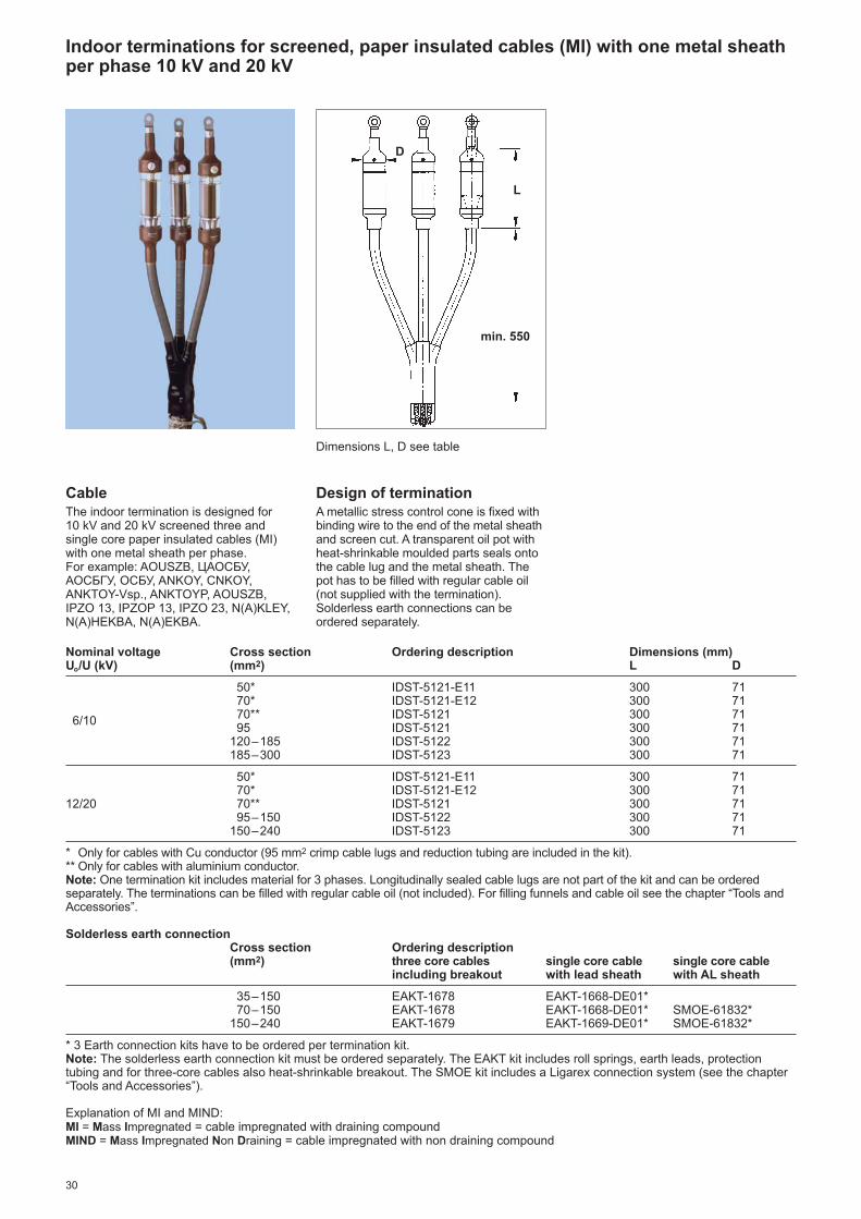
Indoor terminations for screened, paper insulated cables (MI) with one metal sheathper phase 10 kV and 20 kV
CableThe indoor termination is designed for10 kV and 20 kV screened three andsingle core paper insulated cables (MI)with one metal sheath per phase.For example: AOUSZB, ЦАОСБУ,АОСБГУ, ОСБУ, ANKOY, CNKOY,ANKTOY-Vsp., ANKTOYP, AOUSZB,IPZO 13, IPZOP 13, IPZO 23, N(A)KLEY,N(A)HEKBA, N(A)EKBA.
Design of terminationA metallic stress control cone is fixed withbinding wire to the end of the metal sheathand screen cut. A transparent oil pot withheat-shrinkable moulded parts seals ontothe cable lug and the metal sheath. Thepot has to be filled with regular cable oil(not supplied with the termination).Solderless earth connections can beordered separately.
Dimensions L, D see table
Nominal voltage Cross section Ordering description Dimensions (mm)Uo/U (kV) (mm2) L D
50* IDST-5121-E11 300 7170* IDST-5121-E12 300 7170** IDST-5121 300 716/1095 IDST-5121 300 71
120–185 IDST-5122 300 71185–300 IDST-5123 300 71
50* IDST-5121-E11 300 7170* IDST-5121-E12 300 71
12/20 70** IDST-5121 300 7195–150 IDST-5122 300 71
150–240 IDST-5123 300 71
* Only for cables with Cu conductor (95 mm2 crimp cable lugs and reduction tubing are included in the kit).** Only for cables with aluminium conductor.Note: One termination kit includes material for 3 phases. Longitudinally sealed cable lugs are not part of the kit and can be orderedseparately. The terminations can be filled with regular cable oil (not included). For filling funnels and cable oil see the chapter “Tools andAccessories”.
Solderless earth connectionCross section Ordering description(mm2) three core cables single core cable single core cable
including breakout with lead sheath with AL sheath
35–150 EAKT-1678 EAKT-1668-DE01*70–150 EAKT-1678 EAKT-1668-DE01* SMOE-61832*
150–240 EAKT-1679 EAKT-1669-DE01* SMOE-61832*
* 3 Earth connection kits have to be ordered per termination kit.Note: The solderless earth connection kit must be ordered separately. The EAKT kit includes roll springs, earth leads, protectiontubing and for three-core cables also heat-shrinkable breakout. The SMOE kit includes a Ligarex connection system (see the chapter“Tools and Accessories”).
Explanation of MI and MIND:MI = Mass Impregnated = cable impregnated with draining compoundMIND = Mass Impregnated Non Draining = cable impregnated with non draining compound
L
D
min. 550

3132
Long term testing of 10 kV paper cablesaccessories type GUSJ and GUST atRaychem products developmentlaboratories

32
Indoor terminations for flexible, screened, rubber insulated cables 6 kV
CableThe termination is designed for 6 kVscreened, flexible, rubber insulated cableswith one or three earth cores.For example: NTSC, КГЭ, КГЭТ, Ogb,Ogc-G, CHCU, CBVU, EpN 64i65,EpN (BN) 64i74, EpN (BN) 76i78,EpN (BN) 78/53.
Dimension L see table
For cables with 1 or up to 3 earth cores
Nominal voltage Cross section Ordering description by lengthUo/U (kV) (mm2) adjustable* L = 450 mm** L = 1200 mm**
Cables with 1 earth core10/10– 70/ 70 EMKT-7A4IH2 EMKT-7A4IH595/95–185/185 EMKT-7B4IH2 EMKT-7B4IH5
3,5/6Cables with up to 2 earth core50–95 EMKT-6I/50-95
Cables with 3 earth cores25/10– 70/16 EMKT-7E6IH2 EMKT-7E6IH595/16–185/35 EMKT-7F6IH2 EMKT-7F6IH5
* The core lengths L can be selected between 500 mm each or staggered with minimum core length 300 mm.** The core lengths can be reduced to the requirements at the place of installation, the minimum core length is 300 mm.Note: One termination kit includes material for 3 phases. Longitudinally sealed cable lugs are not part of the kit and can be orderedseparately.
Terminations for other voltages or core lengths are available on request.
Design of terminationFor cables with up to 2 earth cores and adjustable core lengths.
Stress grading mastic is wrapped aroundthe area of the screen cut. All phase coresare covered with non-tracking insulatingtubing, which is supplied within the kit inone piece of total length 1500 mm. Thusthe length of phase cores can be selectedbetween 500 mm each or staggered withindividual minimum core length 300 mmup to total sum of 1500 mm. The earthcores are covered by insulating tubing and sealed by mastic. The area betweenthe end of the oversheath and the cores issealed and protected by a 4-finger blackbreakout. The cores remain flexible andcan be bent like the cable.
For cables with 1 or up to 3 earth cores.Stress grading mastic is wrapped aroundthe area of the screen cut. All cores arecovered with non-tracking insulatingtubing. The area between the end of theoversheath and the cores is sealed andprotected by a 6- or 4-finger red breakout.The cores remain flexible and can be bentlike the cable.
L

33
CableThe termination is designed for 6 kVscreened, flexible, rubber insulated cableswith one or three earth cores.For example: NTSC, КГЭ, КГЭТ, Ogb,Ogc-G, CHCU, CBVU, EpN 64i65,EpN (BN) 64i74, EpN (BN) 76i78,EpN (BN) 78/53.
Design of terminationFor cables with up to 2 earth cores and adjustable core lengths.Stress grading mastic is wrapped aroundthe area of the screen cut. All phase coresare covered with non-tracking insulatingtubing, which is supplied within the kit inone piece of total length 1500 mm. Thusthe length of phase cores can be selectedbetween 500 mm each or staggered withindividual minimum core length 450 mm upto total sum of 1500 mm. The earth coresare covered by insulating tubing and sealedby mastic. The area between the end of theoversheath and the cores is sealed andprotected by a 4-finger black breakout.Outdoor terminations include in addition 2 sheds per phase. The cores remainflexible and can be bent like the cable.
Outdoor terminations for flexible, screened, rubber insulated cables 6 kV
Nominal voltage Cross section Ordering description by length D No. of Uo/U (kV) (mm2) adjustable* L = 450 mm L = 1200 mm** (mm) skirts
Cables with 1 earth core10/10– 70/ 70 EMKT-7A4OH2 EMKT-7A4OH5 76 3 x 295/95–185/185 EMKT-7B4OH2 EMKT-7B4OH5 85 3 x 2
3,5/6Cables with up to 2 earth core50–95 EMKT-6O/50-95 76 3 x 2
Cables with 3 earth cores25/10– 70/16 EMKT-7E6OH2 EMKT-7E6OH5 76 3 x 295/16–185/35 EMKT-7F6OH2 EMKT-7F6OH5 85 3 x 2
* The core lengths can be selected between 500 mm each or staggered with minimum core length 450 mm.** The core lengths can be reduced to the requirements at the place of installation, the minimum core length is 450 mm.Note: One termination kit includes material for 3 phases. Longitudinally sealed cable lugs are not part of the kit and can be orderedseparately.
Terminations for other voltages or core lengths are available on request.
D
L
Dimensions L, D see table
For cables with 1 or up to 3 earth cores.Stress grading mastic is wrapped aroundthe area of the screen cut. All cores arecovered with non-tracking insulating tubing.The area between the end of theoversheath and the cores is sealed andprotected by a 6- or 4-finger red breakout.Outdoor terminations include in addition2 sheds per phase. The cores remainflexible and can be bent like the cable.

34
Indoor terminations for unscreened, 3-core polymeric insulated cables
6 kV and 10 kV
CableThe indoor termination is designed for 6 kVand 10 kV unscreened three core polymericinsulated cables with armour or copperearth shield.For example: АПВГ, YAKYFtly, YKYFoY,YAKYFpy, AYKCY, CYKCY, CHKCE-R,NAYFGY, PP 41-(A), PP 44-(A), PP45-(A),N(A)YFGY.
Dimension L see table
Nominal voltage Cross section Ordering description Dimension (mm)Uo/U (kV) (mm2) L
EPKT-2041 450
16– 50EPKT-2042 650EPKT-2043 800EPKT-2044 1200
EPKT-2051 4503,5/670–120
EPKT-2052 650andEPKT-2053 8006/10EPKT-2054 1200
EPKT-2061 450
150–240EPKT-2062 650EPKT-2063 800EPKT-2064 1200
Note: One termination kit includes material for 3 phases. Longitudinally sealed cable lugs are not part of the kit and can be orderedseparately. The core lengths can be reduced to the requirements at the place of installation, the minimum core length is 250 mm (450 mm for 10 kV).
Solderless earth connection for cables with armour or copper tape shield
Nominal voltage Cross section Ordering descriptionUo/U (kV) (mm2)
3,5/616– 95 SMOE-60805
120–300 SMOE-60873
16 SMOE-608056/10 25– 95 SMOE-60873
120–300 SMOE-62176
Note: The solderless earth connection kit must be ordered separately. It includes a roll spring and an earth lead.
Terminations for motor connection boxes are available on request.
Design of terminationThe cores are covered with non-trackinginsulating tubing. The area between theend of the oversheath and the cores issealed and protected by a non-trackinginsulating breakout.Solderless earth connections can beordered separately.
L

35
Outdoor terminations for unscreened, 3-core polymeric insulated cables 6 kV and 10 kV
CableThe outdoor termination is designed for6 kV and 10 kV unscreened three corepolymeric insulated cables with armouror copper earth shield.For example: АПВГ , YAKYFtly, YKYFoy,YKYFtly, AYKCY, CYKCY, CHKCE-R,NAYFGY, PP 41-(A), PP 44-(A), PP45-(A),N(A)YFGY.
Dimensions L, D see table
Nominal voltage Cross section Ordering description Dimensions (mm) No. ofUo/U (kV) (mm2) L D skirts
16– 50EPKT-2292 650 76 3 x 1EPKT-2294 1200 76 3 x 1
3,5/670–120
EPKT-2302 650 95 3 x 1and EPKT-2304 1200 95 3 x 16/10
150–240EPKT-2312 650 95 3 x 1EPKT-2314 1200 95 3 x 1
Note: One termination kit includes material for 3 phases. Longitudinally sealed cable lugs are not part of the kit and can be orderedseparately. The core lengths can be reduced to the requirements at the place of installation, the minimum core length is 450 mm.
Solderless earth connection for cables with armour or copper tape shield
Nominal voltage Cross section Ordering descriptionUo/U (kV) (mm2)
3,5/616– 95 SMOE-60805
120–300 SMOE-60873
16 SMOE-608056/10 25– 95 SMOE-60873
120–300 SMOE-62176
Note: The solderless earth connection kit must be ordered separately. It includes a roll spring and an earth lead.
Design of terminationThe cores are covered with non-trackinginsulating tubing. The area between theend of the oversheath and the cores issealed and protected by a non-trackinginsulating breakout. Additional skirts areinstalled onto the tubing (see table).Solderless earth connections can beordered separately.
L
D

36
Nominal Terminations with mechanical lugs Terminations without lugs**voltage Cross Ordering description by length Cross Ordering description by length
section sectionUo/U (kV) (mm2) L = 450 mm L = 1200 mm (mm2) L = 450 mm L = 1200 mm
25– 35 POLT-12B/3XIH1-ML-1-13 POLT-12B/3XIH4-ML-1-13 16– 35 POLT-12B/3XIH1 POLT-12B/3XIH425– 70 POLT-12C/3XIH1-ML-1-13 POLT-12C/3XIH4-ML-1-13 25– 70 POLT-12C/3XIH1 POLT-12C/3XIH4
6/10 70–150 POLT-12D/3XIH1-ML-2-13 POLT-12D/3XIH4-ML-2-13 95–240 POLT-12D/3XIH1 POLT-12D/3XIH495–240 POLT-12D/3XIH1-ML-4-13 POLT-12D/3XIH4-ML-4-13
240–300 POLT-12E/3XIH1-ML-5-13 POLT-12E/3XIH4-ML-5-13 240–500 POLT-12E/3XIH1 POLT-12E/3XIH4
25 POLT-24B/3XIH1-ML-1-13 POLT-24B/3XIH4-ML-1-13 10– 25 POLT-24B/3XIH1 POLT-24B/3XIH425– 70 POLT-24C/3XIH1-ML-1-13 POLT-24C/3XIH4-ML-1-13 25– 50 POLT-24C/3XIH1 POLT-24C/3XIH4
12/20 70–150 POLT-24D/3XIH1-ML-2-13 POLT-24D/3XIH4-ML-2-13 70–185 POLT-24D/3XIH1 POLT-24D/3XIH495–185 POLT-24D/3XIH1-ML-4-13 POLT-24D/3XIH4-ML-4-13
185–300 POLT-24E/3XIH1-ML-5-13 POLT-24E/3XIH4-ML-5-13 185–400 POLT-24E/3XIH1 POLT-24E/3XIH4
50–120 – POLT-42D/3XIH4-ML-2-13 50–120 – POLT-42D/3XIH420/35 150–300 – POLT-42E/3XIH4-ML-5-13 150–300 – POLT-42E/3XIH4
400 – POLT-42F/3XIH4-ML-6-13* 400–500 – POLT-42F/3XIH4
* The termination is also available with mechanical lugs for busbar connection by M20 bolts (modification code -21).** Longitudinally sealed cable lugs are not part of the kit and can be ordered separately.Note: The core lengths can be reduced to the requirements at the place of installation, the minimum core length is 320 mm for Uo/U = 6/10 kV, 360 mm for Uo/U = 12/20 kV and 600 mm for Uo/U = 20/35 kV.For terminations with mechanical lugs for M16 bolts use modification code -17.Solderless earth connections for cables with tape shield have to be ordered separately.
Solderless earth connection for copper tape shielded cables with or without armour
Nominal voltage Cross section Ordering description for cables with tape shield Uo/U (kV) (mm2) without armour with tape armour with wire armour
10– 50 EAKT-1655 – –
6/1035–120 EAKT-1656 EAKT-1675-CEE01 EAKT-1656 + EAKT-164295–240 EAKT-1657 EAKT-1676-CEE01 EAKT-1657 + EAKT-1643
240–500 EAKT-1658 EAKT-1677-CEE01 EAKT-1658 + EAKT-1645
25– 70 EAKT-1656 EAKT-1675-CEE01 –12/20 50–150 EAKT-1657 EAKT-1676-CEE01 EAKT-1657 + EAKT-1643
120–400 EAKT-1658 EAKT-1677-CEE01 EAKT-1658 + EAKT-1645
50–150 EAKT-1658 EAKT-1677-CEE01 EAKT-1658 + EAKT-164420/35 50–300 EAKT-1658 EAKT-1677-CEE01 EAKT-1658 + EAKT-1645
300–500 EAKT-1659 – –
Note: The solderless earth connection kit must be ordered separately. It includes 3 roll springs and 3 earth leads, for cables with tapearmour in addition one larger roll spring. For cables with wire armour, the kit includes clamping rings, an earth lead and a sealing tubing.
Indoor terminations for screened, 3-core polymeric insulated cables 10 kV, 20 kV and 35 kV
Design of terminationThe cable is transformed to quasi 3 singlecore cables which allow crossing thecores even in confined connectionspaces. The cores are covered withconductive tubing from the crutch areaclose to the screen end. The crutch areais sealed and protected with an adhesivelined, conductive breakout which isinstalled over the cores and the end of theoversheath.Yellow stress grading mastic is laid aroundthe end of the screen cut. A non-trackinginsulating tubing coated with stresscontrol and sealing mastic is installedbetween the end of the conductive tubingand the cable lug.Solderless earth connections for cableswith tape shield or armour have to beordered separately. Kits with the modification code -13 includemechanical lugs with a busbar connectionhole for M12 connection bolts, with code -17 for M16 bolts.
CableThe indoor termination is designed for10 kV, 20 kV and 35 kV screened threecore polymeric insulated cables with orwithout armour or copper tape shield.For example: N(A)YSEY, NA2XSY,N2XSEY, NA2XS2Y, АпвБ, АпвБШв,AXEKVCY, AXEKVCEY, N(A)2XSY,XHP 81, EpHP 81, PHP 48,PHP 84,XHP 48.

37
Outdoor terminations for screened, 3-core polymeric insulated cables 10 kV, 20 kV and 35 kV
Design of terminationThe design and installation is the same asfor indoor terminations. In addition skirtsare installed onto the tubing (see table).Solderless earth connections for cableswith tape shield or armour have to beordered separately.Kits with the modification code -13 includemechanical lugs with a busbar connectionhole for M12 connection bolts, with code -17 for M16 bolts.
Dimensions L, D see table
Terminations including mechanical lugs
Nominal voltage Cross section Ordering description by length D No. of Uo/U (kV) (mm2) L = 450 mm L = 1200 mm (mm) skirts
25– 70 POLT-12C/3XOH1-ML-1-13 POLT-12C/3XOH4-ML-1-13 85 3 x 1
6/1070–150 POLT-12D/3XOH1-ML-2-13 POLT-12D/3XOH4-ML-2-13 95 3 x 195–240 POLT-12D/3XOH1-ML-4-13 POLT-12D/3XOH4-ML-4-13 95 3 x 1
240–300 – POLT-12E/3XOH4-ML-5-13 115 3 x 1
25– 70 POLT-24C/3XOH1-ML-1-13 POLT-24C/3XOH4-ML-1-13 85 3 x 3
12/2070–150 POLT-24D/3XOH1-ML-2-13 POLT-24D/3XOH4-ML-2-13 95 3 x 395–185 POLT-24D/3XOH1-ML-4-13 POLT-24D/3XOH4-ML-4-13 95 3 x 3
185–300 – POLT-24E/3XOH4-ML-5-13 115 3 x 3
50–120 – POLT-42D/3XOH4-ML-2-13 95 3 x 420/35 150–300 – POLT-42E/3XOH4-ML-5-13 115 3 x 4
400 POLT-42F/3XOH4-ML-6-13* 135 3 x 4
* The termination is also available with mechanical lugs for busbar connection by M20 bolts (modification code -21).Note: The core lengths can be reduced to the requirements at the place of installation, the minimum core length is 320 mm for Uo/U = 6/10 kV and 460 mm for Uo/U = 12/20 kV and 800 mm for Uo/U = 20/35 kV.For terminations with mechanical lugs for M16 bolts use modification code -17.Solderless earth connections for cables with tape shield have to be ordered separately, see table on the previous page.
Terminations without lugs
Nominal voltage Cross section Ordering description by length D No. of Uo/U (kV) (mm2) L = 450 mm L = 1200 mm (mm) skirts
10– 16 POLT-12A/3XOH1 POLT-12A/3XOH4 76 3 x 1
6/1025– 70 POLT-12C/3XOH1 POLT-12C/3XOH4 85 3 x 195–240 POLT-12D/3XOH1 POLT-12D/3XOH4 95 3 x 1
240–500 – POLT-12E/3XOH4 115 3 x 1
10– 25 POLT-24B/3XOH1 POLT-24B/3XOH4 76 3 x 3
12/2025– 50 POLT-24C/3XOH1 POLT-24C/3XOH4 85 3 x 370–185 POLT-24D/3XOH1 POLT-24D/3XOH4 95 3 x 3
185–400 – POLT-24E/3XOH4 115 3 x 3
50–120 – POLT-42D/3XOH4 95 3 x 420/35 150–300 – POLT-42E/3XOH4 115 3 x 4
400–500 – POLT-42F/3XOH4 135 3 x 4
Note: The core lengths can be reduced to the requirements at the place of installation, the minimum core length is 320 mm for Uo/U = 6/10 kV, 460 mm for Uo/U = 12/20 kV and 800 mm for Uo/U = 20/35 kV.Longitudinally sealed cable lugs are not part of the kit and can be ordered separately.Solderless earth connections for cables with tape shield have to be ordered separately, see table on the previous page.
D
L
38
Indoor terminations for screened, 1-core polymeric insulated cables 10 kV, 20 kV and 35 kV
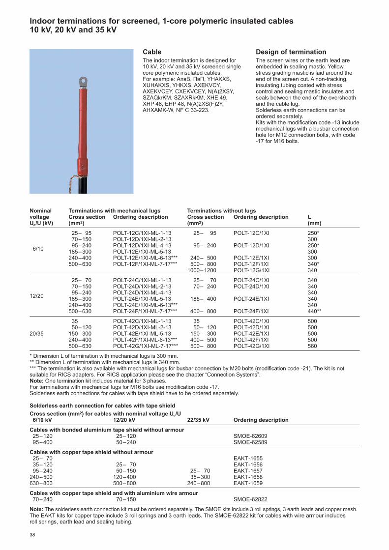
CableThe indoor termination is designed for10 kV, 20 kV and 35 kV screened singlecore polymeric insulated cables.For example: АпвВ, ПвП, YHAKXS,XUHAKXS, YHKXS, AXEKVCY,AXEKVCEY, CXEKVCEY, N(A)2XSY,SZAQkrKM, SZAXRkKM, XHE 49,XHP 48, EHP 48, N(A)2XS(F)2Y,AHXAMK-W, NF C 33-223.
Nominal Terminations with mechanical lugs Terminations without lugsvoltage Cross section Ordering description Cross section Ordering description L Uo/U (kV) (mm2) (mm2) (mm)
25– 95 POLT-12C/1XI-ML-1-13 25– 95 POLT-12C/1XI 250*70–150 POLT-12D/1XI-ML-2-13 300
6/1095–240 POLT-12D/1XI-ML-4-13 95– 240 POLT-12D/1XI 250*
185–300 POLT-12E/1XI-ML-5-13 300240–400 POLT-12E/1XI-ML-6-13*** 240– 500 POLT-12E/1XI 300500–630 POLT-12F/1XI-ML-7-17*** 500– 800 POLT-12F/1XI 340*
1000–1200 POLT-12G/1XI 340
25– 70 POLT-24C/1XI-ML-1-13 25– 70 POLT-24C/1XI 34070–150 POLT-24D/1XI-ML-2-13 70– 240 POLT-24D/1XI 340
12/2095–240 POLT-24D/1XI-ML-4-13 340
185–300 POLT-24E/1XI-ML-5-13 185– 400 POLT-24E/1XI 340240–400 POLT-24E/1XI-ML-6-13*** 340500–630 POLT-24F/1XI-ML-7-17*** 400– 800 POLT-24F/1XI 440**
35 POLT-42C/1XI-ML-1-13 35 POLT-42C/1XI 50050–120 POLT-42D/1XI-ML-2-13 50– 120 POLT-42D/1XI 500
20/35 150–300 POLT-42E/1XI-ML-5-13 150– 300 POLT-42E/1XI 500240–400 POLT-42F/1XI-ML-6-13*** 400– 500 POLT-42F/1XI 500500–630 POLT-42G/1XI-ML-7-17*** 500– 800 POLT-42G/1XI 560
* Dimension L of termination with mechanical lugs is 300 mm.** Dimension L of termination with mechanical lugs is 340 mm.*** The termination is also available with mechanical lugs for busbar connection by M20 bolts (modification code -21). The kit is notsuitable for RICS adapters. For RICS application please see the chapter “Connection Systems”.Note: One termination kit includes material for 3 phases.For terminations with mechanical lugs for M16 bolts use modification code -17.Solderless earth connections for cables with tape shield have to be ordered separately.
Solderless earth connection for cables with tape shield
Cross section (mm2) for cables with nominal voltage Uo/U6/10 kV 12/20 kV 22/35 kV Ordering description
Cables with bonded aluminium tape shield without armour25–120 25–120 SMOE-6260995–400 50–240 SMOE-62589
Cables with copper tape shield without armour25– 70 EAKT-165535–120 25– 70 EAKT-165695–240 50–150 25– 70 EAKT-1657
240–500 120–400 35–300 EAKT-1658630–800 500–800 240–800 EAKT-1659
Cables with copper tape shield and with aluminium wire armour70–240 70–150 SMOE-62822
Note: The solderless earth connection kit must be ordered separately. The SMOE kits include 3 roll springs, 3 earth leads and copper mesh.The EAKT kits for copper tape include 3 roll springs and 3 earth leads. The SMOE-62822 kit for cables with wire armour includes roll springs, earth lead and sealing tubing.
Design of terminationThe screen wires or the earth lead areembedded in sealing mastic. Yellowstress grading mastic is laid around theend of the screen cut. A non-tracking,insulating tubing coated with stresscontrol and sealing mastic insulates andseals between the end of the oversheathand the cable lug.Solderless earth connections can beordered separately.Kits with the modification code -13 includemechanical lugs with a busbar connectionhole for M12 connection bolts, with code -17 for M16 bolts.

39
Outdoor terminations for screened, 1-core polymeric insulated cables 10 kV, 20 kV and 35 kV
Design of terminationThe design and installation is the same asfor indoor terminations. In addition skirtsare installed onto the tubing (see table).Solderless earth connections can beordered separately. Kits with the modifi ca -tion code -13 include mechanicallugs with a busbar connection hole forM12 connection bolts, with code -17for M16 bolts.
Dimensions L, D see table
Nominal Terminations with mechanical lugs Terminations without lugsvoltage Cross section Ordering description Cross section Ordering description Dimensions (mm) No. ofUo/U (kV) (mm2) (mm2) L D skirts
25– 95 POLT-12C/1XO-ML-1-13 25– 95 POLT-12C/1XO 250* 85 3 x 170–150 POLT-12D/1XO-ML-2-13 300 95 3 x 1
6/1095–240 POLT-12D/1XO-ML-4-13 95– 240 POLT-12D/1XO 250* 95 3 x 1
240–400 POLT-12E/1XO-ML-6-13*** 240– 500 POLT-12E/1XO 300 115 3 x 1500–630 POLT-12F/1XO-ML-7-17*** 500– 800 POLT-12F/1XO 340* 135 3 x 1
1000–1200 POLT-12G/1XO 340 135 3 x 1
25– 70 POLT-24C/1XO-ML-1-13 25– 70 POLT-24C/1XO 440 85 3 x 370–150 POLT-24D/1XO-ML-2-13 70– 240 POLT-24D/1XO 440 95 3 x 3
12/2095–240 POLT-24D/1XO-ML-4-13 440 95 3 x 3
185–400 POLT-24E/1XO-ML-6-13*** 185– 400 POLT-24E/1XO 440 115 3 x 3500–630 POLT-24F/1XO-ML-7-17*** 400– 800 POLT-24F/1XO 500** 135 3 x 3
35 POLT-42C/1XO-ML-1-13 35 POLT-42C/1XO 560 85 3 x 450–120 POLT-42D/1XO-ML-2-13 50– 120 POLT-42D/1XO 560 95 3 x 4
20/35 150–300 POLT-42E/1XO-ML-5-13 150– 300 POLT-42E/1XO 560 115 3 x 4240–400 POLT-42F/1XO-ML-6-13*** 400– 500 POLT-42F/1XO 560 135 3 x 4500–630 POLT-42G/1XO-ML-7-17*** 500– 800 POLT-42G/1XO 560 135 3 x 4
* Dimension L of termination with mechanical lugs is 300 mm.** Dimension L of termination with mechanical lugs is 440 mm.*** The termination is also available with mechanical lugs for busbar connection by M20 bolts (modification code -21).Note: One termination kit includes material for 3 phases.For terminations with mechanical lugs for M16 bolts use modification code -17.Solderless earth connections for cables with tape shield have to be ordered separately.
Solderless earth connection for cables with tape shield
Cross section (mm2) for cables with nominal voltage Uo/U6/10 kV 12/20 kV 22/35 kV Ordering description
Cables with bonded aluminium tape shield without armour25–120 25–120 SMOE-6260995–400 50–240 SMOE-62589
Cables with copper tape shield without armour25– 70 EAKT-165535–120 25– 70 EAKT-165695–240 50–150 25– 70 EAKT-1657
240–500 120–400 35–300 EAKT-1658630–800 500–800 240–800 EAKT-1659
Cables with copper tape shield and with aluminium wire armour70–240 70–150 SMOE-62822
Note: The solderless earth connection kit must be ordered separately.The SMOE kits include 3 roll springs and 3 earth leads and copper mesh.The EAKT kits for copper tape include 3 roll springs and 3 earth leads. The SMOE-62822 kit for cables with wire armour includes roll springs, earth lead and sealing tubing.
L
D
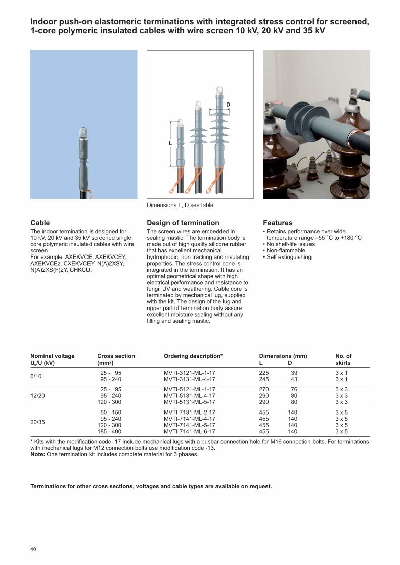
40
CableThe indoor termination is designed for 10 kV, 20 kV and 35 kV screened singlecore polymeric insulated cables with wirescreen.For example: AXEKVCE, AXEKVCEY,AXEKVCEz, CXEKVCEY, N(A)2XSY,N(A)2XS(F)2Y, CHKCU.
Design of terminationThe screen wires are embedded insealing mastic. The termination body ismade out of high quality silicone rubberthat has excellent mechanical,hydrophobic, non tracking and insulatingproperties. The stress control cone isintegrated in the termination. It has anoptimal geometrical shape with highelectrical performance and resistance tofungi, UV and weathering. Cable core isterminated by mechanical lug, suppliedwith the kit. The design of the lug andupper part of termination body assureexcellent moisture sealing without anyfilling and sealing mastic.
Indoor push-on elastomeric terminations with integrated stress control for screened,1-core polymeric insulated cables with wire screen 10 kV, 20 kV and 35 kV
Dimensions L, D see table
Nominal voltage Cross section Ordering description* Dimensions (mm) No. ofUo/U (kV) (mm2) L D skirts
6/1025 - 95 MVTI-3121-ML-1-17 225 39 3 x 195 - 240 MVTI-3131-ML-4-17 245 43 3 x 1
25 - 95 MVTI-5121-ML-1-17 270 76 3 x 312/20 95 - 240 MVTI-5131-ML-4-17 290 80 3 x 3
120 - 300 MVTI-5131-ML-5-17 290 80 3 x 3
50 - 150 MVTI-7131-ML-2-17 455 140 3 x 5
20/3595 - 240 MVTI-7141-ML-4-17 455 140 3 x 5
120 - 300 MVTI-7141-ML-5-17 455 140 3 x 5185 - 400 MVTI-7141-ML-6-17 455 140 3 x 5
* Kits with the modification code -17 include mechanical lugs with a busbar connection hole for M16 connection bolts. For terminationswith mechanical lugs for M12 connection bolts use modification code -13.Note: One termination kit includes complete material for 3 phases.
Terminations for other cross sections, voltages and cable types are available on request.
D
L
Features• Retains performance over wide
temperature range –55 °C to +180 °C• No shelf-life issues• Non-flammable• Self extinguishing

41
Nominal voltage Cross section Ordering description* Dimensions (mm) No. ofUo/U (kV) (mm2) L D skirts
6/1025 - 95 MVTO-3121-ML-1-17 270 61 3 x 395 - 240 MVTO-3131-ML-4-17 290 76 3 x 3
25 - 95 MVTO-5121-ML-1-17 350 97 3 x 512/20 95 - 240 MVTO-5131-ML-4-17 370 101 3 x 5
120 - 300 MVTO-5131-ML-5-17 370 101 3 x 5
50 - 150 MVTO-7131-ML-2-17 655 140 3 x 8
20/3595 - 240 MVTO-7141-ML-4-17 660 140 3 x 8
120 - 300 MVTO-7141-ML-5-17 660 140 3 x 8185 - 400 MVTO-7141-ML-6-17 660 140 3 x 8
* Kits with the modification code -17 include mechanical lugs with a busbar connection hole for M16 connection bolts. For terminationswith mechanical lugs for M12 connection bolts use modification code -13.Note: One termination kit includes complete material for 3 phases.
Terminations for other cross sections, voltages and cable types are available on request.
CableThe outdoor termination is designed for10 kV, 20 kV and 35 kV screened singlecore polymeric insulated cables with wirescreen.For example: AXEKVCE, AXEKVCEY,AXEKVCEz, CXEKVCEY, N(A)2XSY,N(A)2XS(F)2Y, CHKCU.
Design of terminationThe screen wires are embedded insealing mastic. The termination body is made out of high quality silicone rubberthat has excellent mechanical,hydrophobic, non tracking and insulatingproperties. The stress control cone isintegrated in the termination. It has an optimal geometrical shape with highelectrical performance and resistance to fungi, UV and weathering. Cable coreis terminated by mechanical lug, suppliedwith the kit. The design of the lug andupper part of termination body assureexcellent moisture sealing without anyfilling and sealing mastic.
Outdoor push-on elastomeric terminations with integrated stress control forscreened, 1-core polymeric insulated cables with wire screen 10 kV, 20 kV and 35 kV
Dimensions L, D see table
D
Features• Retains performance over wide
temperature range –55 °C to +180 °C• No shelf-life issues• Non-flammable• Self extinguishing
L

42
CableThe termination is designed for screenedsingle core polymeric insulated cableswith wire shield or metal sheath, crosssection from 35 mm2 to 240 mm2 anddiameter over insulation between 26 mmand 52 mm. Cables designed for D.C.voltages 111 kV or 150 kV usually meetthe dimensional requirements.
Ordering Description Cable dimensions Termination dimensionsCross Diameter of Diameter over Max. diameter L D Numbersection conductor dielectric of cable of sheds(mm2) (mm) (mm) (mm) (mm) (mm)
FCEV-111 35– 95 6–11,5 26–38 53 500 165 1
FCEV-150 35– 95 6–11,5 26–38 53 700 165 2
FCEV-150-1 95–240 10,5–21,5 38–52 73 700 165 2
Note: The termination FCEV is supplied as a single phase termination. Terminations for other cable types or dimensions are available on request.
Terminations for screened, polymeric insulated Filter Cables up to 150 kV D.C.
Dimensions L, D see table
D
L
Overview of qualification tests:
Type of test Passed requirementsFCEV 111 FCEV 150
Partial discharge test < 3 pC at 42 kV AC < 3 pC at 60 kV AC
DC withstand test > 8 hours at -200 kV > 8 hours at -275 kV> 8 hours at +200 kV > 8 hours at +275 kV
Impulse test > 1000 times at -240 kV > 1000 times at -320 kV(wave shape 1,2/50 µs, chopped) > 1000 times at +240 kV > 1000 times at +320 kV
AC withstand test > 10 minutes at 60 kV > 10 minutes at 85 kV
Detailed test reports are available on request.
Design of terminationThe cable is prepared in the same simpleand easy way as for Raychem mediumvoltage terminations without sanding or penciling. Based on the design ofRaychem high voltage terminations,the filter cable termination consists of a staggered layer of stress control tubingand patches.
A heat-shrinkable non-tracking insulationtubing and shed are shrunk over thestress control system and ensure a reliable seal to the lug and theoversheath. A mechanical lug cove ringcross sections from 35 mm2 to 95 mm2
or 95 mm2 to 240 mm2 is supplied withthe kit. The mechanical lug has a M10thread on the top for easy connection to connecting busbars. The termination is supplied as a singlephase termination. A solderless earthconnection for cables with metal sheath is included in the termination kit.
Testing and performanceNeither national nor international secifi -cations exist for filter cable terminations.By understanding the specific operationrequirements of a filter cable termination,Raychem developed a test specificationand qualified the filter cable terminationFCEV to these requirements. The over -view of qualification tests is summarizedin a table below.
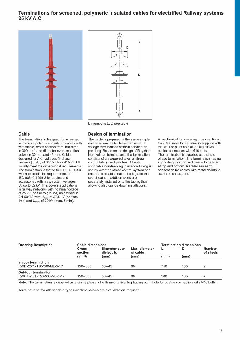
43
CableThe termination is designed for screenedsingle core polymeric insulated cables withwire shield, cross section from 150 mm2
to 300 mm2 and diameter over insulationbetween 30 mm and 45 mm. Cablesdesigned for A.C. voltages (3 phasesystems) Uo/Um of 30/52 kV or 41/72,5 kVusually meet the dimensional requirements.The termination is tested to IEEE-48-1990which exceeds the requirements of IEC-60840-1999-2 for cables andaccessories with max. system voltages Um up to 52 kV. This covers applications in railway net works with nominal voltage of 25 kV (phase to ground) as defined inEN-50163 with Umax1 of 27,5 kV (no timelimit) and Umax2 of 29 kV (max. 5 min).
Ordering Description Cable dimensions Termination dimensionsCross Diameter over Max. diameter L D Numbersection dielectric of cable of sheds(mm2) (mm) (mm) (mm) (mm)
Indoor terminationRWIT-25/1x150-300-ML-5-17 150–300 30–45 60 750 165 2
Outdoor terminationRWOT-25/1x150-300-ML-5-17 150–300 30–45 60 900 165 4
Note: The termination is supplied as a single phase kit with mechanical lug having palm hole for busbar connection with M16 bolts.
Terminations for other cable types or dimensions are available on request.
Terminations for screened, polymeric insulated cables for electrified Railway systems25 kV A.C.
Dimensions L, D see table
Design of terminationThe cable is prepared in the same simpleand easy way as for Raychem mediumvoltage terminations without sanding orpenciling. Based on the design of Raychemhigh voltage terminations, the terminationconsists of a staggered layer of stresscontrol tubing and patches. A heat-shrinkable non-tracking insulation tubing isshrunk over the stress control system andensures a reliable seal to the lug and theoversheath. In addition skirts areseparately installed onto the tubing thusallowing also upside down installations.
A mechanical lug covering cross sectionsfrom 150 mm2 to 300 mm2 is supplied withthe kit. The palm hole of the lug allowsbusbar connection with M16 bolts. The termination is supplied as a singlephase termination. The termination has nosupporting function and needs to be fixedat top and bottom. A solderless earthconnection for cables with metal sheath isavailable on request.
L
D

44
Con
nect
ion
Sys
tem
s

45
Connection Systems for MV gas-insulated switchgear
Connection systems for bushings according to EN 50181 type C1 (630 A) and type C2 (1250 A)
Insulated T-adapter and straight adapter system for polymeric and paper insulated cables 10 kV, 15 kV and 20 kV 46
Screened, separable T-connection system for polymeric insulated cables 10 kV, 15 kV, 20 kV and 35 kV 48
Connection systems for bushings according to EN 50181 type B (400 A)
Screened, separable elbow connection system for polymeric insulated cables 20 kV and 35 kV 50
Connection systems for bushings according to EN 50181 type A (250 A)
Screened, separable elbow and straight connection system for polymeric insulated cables 10 kV, 15 kV and 20 kV 52

46
1 Bushing cone2 RICS - adapter3 RCAB - adapter4 Raychem termination5 Backplug
1
4
3
4
1
2
The insulated adapter system providesperfect sealing, electrical insulation andan electrical connection betweenRaychem terminations and gas-insulatedswitchgear up to 24 kV. It is designed to fitbushing profiles according to EN 50181type C. The insulating adapters arecompatible with all heat-shrink Raychemterminations.
RICS, RCAB - Insulated T-adapter and straight adapter system for gas-insulatedswitchgears with bushings according to EN 50181 type C1 (630 A) and C2 (1250 A), 10 kV, 15 kV and 20 kV
Test plug for cable testing:Cables can be tested while the T-adapterand the cable are connected to theswitchgear. The backplug of the RICSadapter is removed and the test plug isscrewed in instead of the backplug. Forphase to phase testing, test plugs ofdifferent lengths must be used.
Standard version, Length = 290 mmRICS-5002-50-24Long version, Length = 390 mmRICS-5002-50-25
RICS - T-adapterThick walled insulating body made of highquality elastomer with sealing face overthe termination, bushing cone and plug.The electrical connection is made with a terminal stud and the cable lug of thetermination. A special plug which allowscable testing without disconnecting theadapter is also offered. The design of the adapter for connectingthe surge arrester is basically identical.The elastomer insulating body has an additional lead-in duct for the surgearrester type RDA. Adapters for two cableconnections are also available.For double T-connections, the secondadapter is of special design and includesconnection plug, insulating body, fixingnuts, terminal stud and backplug. It can be combined with first adapters of type RICS 57x3-CU, but not withadapter for surge arresters type RICS-51x9.
RCAB - Straight adapterA highly flexible insulating body made ofhigh quality elastomer provides a hermeticseal over the cone of the bushing and thetermination. The cable lug of thetermination is simply connected to a terminal stud with a bolt and nut. Evenin confined spaces the adapter can beeasily pulled down from the bushing givingaccess for e.g. cable testing. RCAB is supplied in a 3-phase setcomplete with installation instruction.Fixing bolts and nuts, terminal stud andcable lugs are not included.Terminal studs with a M16 thread can beordered separately as EXRM-1366. Theadapter is to be used in combination withRaychem terminations:Up to 12 kV35-300 mm2 RCAB-4120Up to 24 kV50-300 mm2 RCAB-5120
5
Accessories for RICS adapter
Surge arrester type RDA for T-Adapters type RICS-51x9:The surge arrester type RDA is speciallydeveloped for applications in gas-insulated switchgear. They are availablefor voltages from 6 kV to 26 kV. Detailinformation and technical data areavailable from your local Raychemproducts representative.Blind Plugs type RICS-5009-50-22 can betemporarily installed instead of RDA surgearresters.
Double T-adapters for connections to630 A and 1250 A rated bushings withprofile according to EN 505181 type C:Each RICS adapter is rated for max. 630 A.For double T-connections, a special firstadapter with M16 stud of type RICS-5733-Cu or RICS 5743-Cu must be used. Application ranges are the sameas for types RICS 51x3 shown in table.
L
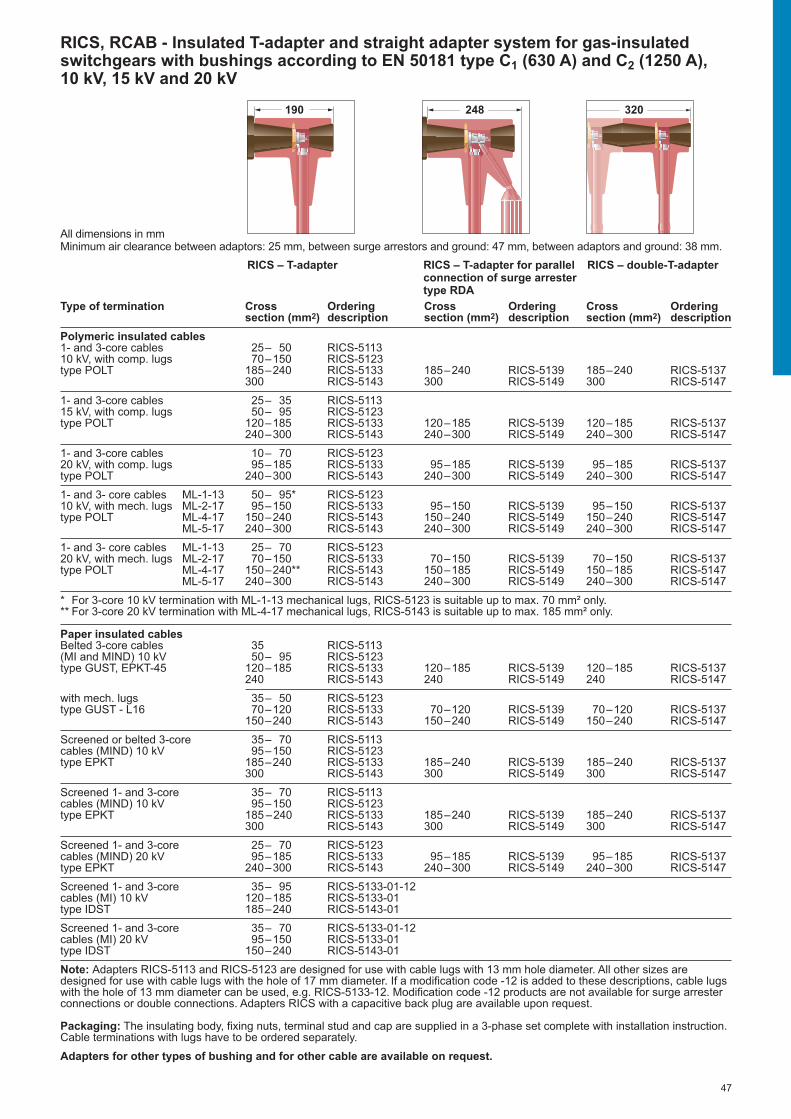
47
Type of termination Cross Ordering Cross Ordering Cross Orderingsection (mm2) description section (mm2) description section (mm2) description
Polymeric insulated cables1- and 3-core cables 25– 50 RICS-511310 kV, with comp. lugs 70–150 RICS-5123type POLT 185–240 RICS-5133 185–240 RICS-5139 185–240 RICS-5137
300 RICS-5143 300 RICS-5149 300 RICS-5147
1- and 3-core cables 25– 35 RICS-511315 kV, with comp. lugs 50– 95 RICS-5123type POLT 120–185 RICS-5133 120–185 RICS-5139 120–185 RICS-5137
240–300 RICS-5143 240–300 RICS-5149 240–300 RICS-5147
1- and 3-core cables 10– 70 RICS-512320 kV, with comp. lugs 95–185 RICS-5133 95–185 RICS-5139 95–185 RICS-5137type POLT 240–300 RICS-5143 240–300 RICS-5149 240–300 RICS-5147
1- and 3- core cables ML-1-13 50– 95* RICS-512310 kV, with mech. lugs ML-2-17 95–150 RICS-5133 95–150 RICS-5139 95–150 RICS-5137type POLT ML-4-17 150–240 RICS-5143 150–240 RICS-5149 150–240 RICS-5147
ML-5-17 240–300 RICS-5143 240–300 RICS-5149 240–300 RICS-5147
1- and 3- core cables ML-1-13 25– 70 RICS-512320 kV, with mech. lugs ML-2-17 70–150 RICS-5133 70–150 RICS-5139 70–150 RICS-5137type POLT ML-4-17 150–240** RICS-5143 150–185 RICS-5149 150–185 RICS-5147
ML-5-17 240–300 RICS-5143 240–300 RICS-5149 240–300 RICS-5147
* For 3-core 10 kV termination with ML-1-13 mechanical lugs, RICS-5123 is suitable up to max. 70 mm² only.** For 3-core 20 kV termination with ML-4-17 mechanical lugs, RICS-5143 is suitable up to max. 185 mm² only.
Paper insulated cablesBelted 3-core cables 35 RICS-5113(MI and MIND) 10 kV 50– 95 RICS-5123type GUST, EPKT-45 120–185 RICS-5133 120–185 RICS-5139 120–185 RICS-5137
240 RICS-5143 240 RICS-5149 240 RICS-5147
with mech. lugs 35– 50 RICS-5123type GUST - L16 70–120 RICS-5133 70–120 RICS-5139 70–120 RICS-5137
150–240 RICS-5143 150–240 RICS-5149 150–240 RICS-5147
Screened or belted 3-core 35– 70 RICS-5113cables (MIND) 10 kV 95–150 RICS-5123type EPKT 185–240 RICS-5133 185–240 RICS-5139 185–240 RICS-5137
300 RICS-5143 300 RICS-5149 300 RICS-5147
Screened 1- and 3-core 35– 70 RICS-5113cables (MIND) 10 kV 95–150 RICS-5123type EPKT 185 –240 RICS-5133 185–240 RICS-5139 185–240 RICS-5137
300 RICS-5143 300 RICS-5149 300 RICS-5147
Screened 1- and 3-core 25– 70 RICS-5123cables (MIND) 20 kV 95–185 RICS-5133 95–185 RICS-5139 95–185 RICS-5137type EPKT 240–300 RICS-5143 240–300 RICS-5149 240–300 RICS-5147
Screened 1- and 3-core 35– 95 RICS-5133-01-12cables (MI) 10 kV 120–185 RICS-5133-01type IDST 185–240 RICS-5143-01
Screened 1- and 3-core 35– 70 RICS-5133-01-12cables (MI) 20 kV 95–150 RICS-5133-01type IDST 150–240 RICS-5143-01
Note: Adapters RICS-5113 and RICS-5123 are designed for use with cable lugs with 13 mm hole diameter. All other sizes aredesigned for use with cable lugs with the hole of 17 mm diameter. If a modification code -12 is added to these descriptions, cable lugswith the hole of 13 mm diameter can be used, e.g. RICS-5133-12. Modification code -12 products are not available for surge arresterconnections or double connections. Adapters RICS with a capacitive back plug are available upon request.
Packaging: The insulating body, fixing nuts, terminal stud and cap are supplied in a 3-phase set complete with installation instruction.Cable terminations with lugs have to be ordered separately.
Adapters for other types of bushing and for other cable are available on request.
RICS, RCAB - Insulated T-adapter and straight adapter system for gas-insulatedswitchgears with bushings according to EN 50181 type C1 (630 A) and C2 (1250 A), 10 kV, 15 kV and 20 kV
RICS – double-T-adapterRICS – T-adapter RICS – T-adapter for parallelconnection of surge arrestertype RDA
All dimensions in mmMinimum air clearance between adaptors: 25 mm, between surge arrestors and ground: 47 mm, between adaptors and ground: 38 mm.
190 248 320

48
Raychem screened separable T-connectionsystem is designed to connect single-coreor three-core (with installed trifurcation kit)polymeric insulated cables to gas-insulated switchgear or other equipmentwith bushings type C in accordance withEN 50181, specified up to 42 kV.Connections can be made in a right-angleconfiguration, also for 2 or 3 cables inparallel. All cables connected in theswitchgear in parallel configuration mustbe individually mechanically fixed. Parallelconnections to 630 A or 1250 A ratedbushings with profile type C1 or C2according to EN 505181 are possible witheach RSTI. Maximum continuous currentrating for T-connection system seriesRSTI-x8xx is 800 A. Parallel connectionsof RSTI-x8xx and RSTI-CC-x8xx cancarry out 1250 A as well as single cableequipped with RSTI-x9xx.
Made of a highly modified silicone rubberand protected with an outer conductiveshield connected to earth, Raychem RSTIscreened T-connection system is thussuitable for both indoor and outdoorinstallations. Oversheath testing can beperformed without removal of the RSTIsystem.
The modern design and material selectionin combination with the Raychemdesigned high performance mechanicallug allows a large application range,covering most common cable sizes withjust one kit.The overall and cut back dimensions aredesigned for use of minimum spacerequired in the termination box, evendouble connections fit within moststandard boxes.Raychem RSTI screened T-connectionsystem is equipped with a capacitive testpoint to determine if the circuit isenergized. The capacitive test point isprotected by a conductive cap.
Surge arrester RSTI-SA for screened,separable T-connection systemThe screened gapless surge arrester isdesigned either for a direct connectiononto outer cone bushings in accordanceto EN50181 with interface type C or forparallel connection mating to the rearentry of the base RSTI screened T-connection system designed for systemvoltage up to 35 kV. Detailed informationand technical data are available onrequest.
The combination of screened T-connection system and surge arresterexceeds the requirements of CENELECHD 629.1.S2 which includes BS, VDEand other international specifications.
RSTI - Screened, separable T-connection system for gas-insulated switchgears withbushings according to EN 50181 type C1 (630 A) and C2 (1250 A), 10 kV, 15 kV, 20 kVand 35 kV
InstallationThe design of T-connection system allowsthe use of all common cable core screenremoval tools with a minimum cutback upto 40 mm. After cable preparation, thelubricated stress control adapter is simplyslid into place. The high performancemulti range mechanical lugs are quicklyinstalled by shearing off the bolts. Whenlubricated, the screened connector bodycan be easily slid onto the cable end and fixed to the bushing by a threaded pin and nut. The open end is sealed by a rear plug or by a connection plug, whichallows parallel connection of cables.
Double connections Only T-connector and coupling connectormust be ordered for parallel connection of cables.
The required installation dimensionsD/d/H are as follows:- 285/101/299 for connection of RSTI-58- 295/101/339 for connection of RSTI-68- 315/120/411 for connection of RSTI-x9
Configuration of RSTI-58 as double T-connection
Cut-away drawing of RSTI-58xx:1 Screened body 2 Inner screen3 Mechanical lug4 Stress cone adapter5 Earthing eye and ground lead6 Threaded pin7 Rear plug with test point8 Test point9 Conductive end cap
1
2
4
3
7
6
8
9
5
d
H
D

49
RSTI - Screened, separable T-connection system for gas-insulated switchgears withbushings according to EN 50181 type C1 (630 A) and C2 (1250 A), 10 kV, 15 kV, 20 kVand 35 kV
RSTI - T-connection system
Nominal voltage Cross section Ordering description Diameter over Uo/U (kV) (mm2) T-connector Coupling connector core insulation (mm)
35 - 95 RSTI-5851 RSTI-CC-5851 12,7 – 25,095 - 240 RSTI-5853 RSTI-CC-5853 17,0 – 32,6
6/10185 - 300 RSTI-5855 RSTI-CC-5855 21,3 – 34,6400 RSTI-3951 RSTI-CC-3951 28,9 – 36,4500 RSTI-3952 RSTI-CC-3952 28,9 – 36,4630 RSTI-3953 RSTI-CC-3953 34,0 – 45,4
35 - 70 RSTI-5851 RSTI-CC-5851 12,7 – 25,095 - 240 RSTI-5854 RSTI-CC-5854 21,3 – 34,6
8,7/15 185 - 300 RSTI-5855 RSTI-CC-5855 21,3 – 34,6and 400 RSTI-5951 RSTI-CC-5951 34,0 – 45,412/20 500 RSTI-5952 RSTI-CC-5952 34,0 – 45,4
630 RSTI-5953 RSTI-CC-5953 39,1 – 59,0800 RSTI-5954 RSTI-CC-5954 39,1 – 59,0
35 - 95 RSTI-6851 RSTI-CC-6851 22,4 – 35,595 - 150 RSTI-6852 RSTI-CC-6852 22,4 – 35,5
120 - 240 RSTI-6853 RSTI-CC-6853 28,9 – 42,020/35 180 - 300 RSTI-6855 RSTI-CC-6855 28,9 – 42,0
400 RSTI-6951 RSTI-CC-6951 34,0 – 45,4500 - 630 RSTI-6952 RSTI-CC-6952 39,1 – 59,0800 RSTI-6953 RSTI-CC-6953 39,1 – 59,0
Scope of supply: Screened connector body, stress control adapter, mechanical lug (suitable for aluminium and copper conductors),fixing nuts, terminal stud, backplug and lubricant supplied in a 3-phase set complete with installation instruction.
Solderless earth connection for cables with aluminium or copper tape shield
Cross section (mm2) for cables with nominal voltage Uo/U6/10 kV 8,7/15 kV 12/20 kV Ordering description
35 - 120 35 - 120 35 - 120 SMOE-6287195 - 400 70 - 300 50 - 240 SMOE-62872
Note: The solderless earth connection kit must be ordered separately. The SMOE kits include 3 roll springs, 3 earth leads, 3 heatshrinkable insulating tubing and copper mesh.
Trifurcation kit for screened, 3-core polymeric insulated cables with wire shield and without armour
Dia. over core insulation (mm) Dia. over cable (mm) Max. tail length* (mm) Ordering description
13,7 - 25,0 46,0 - 67,0 600 RSTI-TRF0117,6 - 35,6 50,0 - 90,0 600 RSTI-TRF0225,6 - 43,0 85,0 - 140,0 600 RSTI-TRF03
* Trifurcation kits with longer tail length are available on request.Note: Trifurcation kits must be ordered separately.
RSTI system accessories
Test rodsCables can be tested while the RSTIconnector and the cables are connectedto the switchgear.
Earthing plug for cable earthingCables can be earthed while the RSTIconnector and the cable are connected tothe switchgear.
Termination plug as live end sealAllows termination and sealing of theRSTI connectors in case that they are notinstalled on a switchgear bushing. Thetermination plug must be installed beforeapplying any voltage (e.g. cable systemtest).
Insulated end coverInsulated dead end for switchboardbushing according to EN 50181 types C.
Set of 3 test rods with threading reducerM16 / M12RSTI-68TRA2x length of 310 mm, 1x length of 460 mm.RSTI-68TR3x length of 310 mm.RSTI-68TRL3x length of 460 mm.
RSTI-68EA25Set of 3 pieces with ball diameter 25 mm.
RSTI-68EA20Set of 3 pieces with ball diameter 20 mm.
RSTI-68TPSet of 3 pieces.
RSTI-N66RCSet of 3 pieces.

50
Raychem RSES-64xx screened,separable elbow connection system isdesigned to connect single- and three-core polymeric cables to medium voltagegas-insulated switchgear and otherequipment using bushings type Bspecified for 400 A up to 35 kV inaccordance with EN 50181.
Made of a highly modified silicone rubberand protected by a thin-walled outerconductive screen connected to earth,elbow connection system is equally suitedfor indoor and outdoor installation.
Supporting a wide application range, thedesign incorporates one body and twostress cone adapters to cover all cross-sections from 50 to 300 mm2. Mechanicallugs, included in the kit, accept bothaluminium and copper conductors.The overall and cut back dimensions are designed to take up minimum spacein the terminal box. RSES-64xx elbowconnection system is equipped with a capacitive test point for determiningwhether the circuit is energized. A conductive cap protects this test point.
RSES-64xx - Screened, separable elbow connection system for gas-insulatedswitchgears with bushings according to EN 50181 type B (400 A), 20 kV and 35 kV
Cut-away drawing of RSES-64xx:1 Screened body 2 Inner screen3 Mechanical lug4 Stress cone adapter5 Earthing eye and ground lead6 Contact pin7 Test point8 Conductive covering cap9 Stainless steel bail
InstallationAfter a cable preparation and lubrication,the stress control adapter is simply slidinto place and cable core terminated bymechanical lug with shear bolts. Followedby pushing the screened elbow body ontostress cone. The installation is finished by fixing the connection system on theequipment bushing with the bail.Main kit components, the stress cone and screened body of connection system,can be virtually installed under anyconditions.
1
2
4
5
3
7
6
8
9

51
RSES-64xx - Screened, separable elbow connection system for gas-insulatedswitchgears with bushings according to EN 50181 type B (400 A), 20 kV and 35 kV
Screened separable elbow connection system with shear bolts mechanical lugs
Nominal voltage Cross section Ordering description Diameter over Uo/U (kV) (mm²) core insulation (mm)
70 – 95 RSES-6451 22,4 – 35,512/20 95 – 240 RSES-6452 22,4 – 35,5
185 – 300 RSES-6454 22,4 – 35,5
50 – 95 RSES-6451 22,4 – 35,5
20/3595 – 150 RSES-6452 22,4 – 35,5
120 – 240 RSES-6453 28,9 – 42,0185 – 300 RSES-6455 28,9 – 42,0
Applications
Single connectionMaterial requested for 3 phases:1 x RSES-64xx (kit)
Dimensions in mmNote:*Plastic insulated cable, 36 kV, 300 mm2
215
130
285
79
max. Ø 86*
Trifurcation kit for screened, 3-core polymeric insulated cables with wire shield and without armour
Dia. over core insulation (mm) Dia. over cable (mm) Max. tail length* (mm) Ordering description
13,7 - 25,0 46,0 - 67,0 600 RSTI-TRF0117,6 - 35,6 50,0 - 90,0 600 RSTI-TRF0225,6 - 43,0 85,0 - 140,0 600 RSTI-TRF03
* Trifurcation kits with longer tail length are available on request.Note: Trifurcation kits must be ordered separately.

52
1 Screened body2 Capacitive test point3 Stress cone4 Conductive Cable Entrance5 Earthing eye6 Inner Screen7 Retaining Shoulder8 Compression pin-connector9 Lifting Eye
10 Pin11 Compression Connector
Raychem screened separable elbowRSES-52xx and straight RSSS-52xxconnection systems are designed toconnect single-core polymeric cables togas-insulated switchgears or transformersup to 24 kV. The adapter seals onbushings according to EN 50181 type A(250 A).
DesignThe thick walled separable connectionsystem with an integrated stress controlprovides sealing and electrical connectionto the cone of the bushing and the cable.Made of crosslinked EPDM and protectedwith a minimum 3 mm mouldedconductive shield connected to the earth,the connection system is suitable for bothindoor and outdoor installations. Thespecial design and material selection ofthe connection system allow its use on a wide range of cable dimensions. Thusthe connection system is independent of cable tolerances and special cableadapters are not required. The cablepreparation and cut-back dimensions arethe same for both straight and elbowconnection system.
The connection system is equipped with a capacitive test point to ensure that thecircuit is not energized beforedisconnection. The capacitive test point is protected by a conductive cap.
High strength bimetallic DIN-compressionconnectors tested to VDE 0220 aresupplied within the kit to connect bothaluminium and copper conductor cables.
RSES, RSSS - Screened, separable elbow and straight connection system for gasinsulated switchgears and transformers with bushings according to EN 50181 type A (250 A), 10 kV, 15 kV and 20 kV
InstallationAfter a cable preparation and crimping ofthe connector, the connection system canbe simply slid into place virtually under allconditions. For elbow connection system,the connection pin is screwed into theconnector, a hexagon wrench is providedwith the kit. A separable mounting systemallows an easy installation of the Raychemconnection system to the bushing. Toprovide a reliable environmental sealbetween the connection system and theoversheath a cold-applied Rayvolvetubing or a heat-shrinkable phasemarking tubing is offered.
Screened elbow connection system Screened straight connection system
8
6
5
3
4
1
2
7
5
3
4
9
10
1
2
11
6

53
Superior environmental sealThe roll-on Rayvolve sleeve is used inconjunction with pressure sensitive masticand is simply rolled into place to provide a reliable moisture seal. Kits with modification code -R include the Rayvolve sealing system.
The heat-shrinkable phase markingtubing provides a moisture seal andadditional phase marking. Kits withmodification code -P include thephase marking tubing.
RSES, RSSS - Screened, separable elbow and straight connection system for gasinsulated switchgears and transformers with bushings according to EN 50181 type A (250 A), 10 kV, 15 kV and 20 kV
RSES- Elbow connection systemThe screened body, compressionconnector (for aluminium and copperconductors), pin, hexagonal wrench,retaining clamp and lubricant supplied in a 3-phase set complete with installationinstruction. Kits with modification code -Rinclude in addition the Rayvolve sealingsystem, kits with modification code -P theheat-shrinkable phase marking tubing.
RSSS - Straight connection systemThe screened body, pin connector (foraluminium and copper conductors),retaining collar and lubricant supplied in a 3-phase set complete with installationinstruction. Kits with modification code -Rinclude in addition the Rayvolve sealingsystem, kits with modification code -P theheat-shrinkable phase marking tubing.
Scope of supply
Nominal voltage Cross section Diameter over core insulation Ordering description of connection systemUo/U (kV) (mm2) (mm) Elbow Straight
25 13,5–17,4 RSES-5202 RSSS-520235 13,5–17,4 RSES-5203 RSSS-5203
6/1050 13,5–17,4 RSES-5205 RSSS-520570 16,3–20,8 RSES-5217 RSSS-521795 16,3–20,8 RSES-5219 RSSS-5219
120 19,6–24,1 RSES-5224
25 13,5–17,4 RSES-5202 RSSS-520235 16,3–20,8 RSES-5213 RSSS-5213
8,7/1550 16,3–20,8 RSES-5215 RSSS-521570 19,6–24,1 RSES-5227 RSSS-522795 19,6–24,1 RSES-5229 RSSS-5229
120 23,1–28,7 RSES-5234
25 16,3–20,8 RSES-5212 RSSS-521235 16,3–20,8 RSES-5213 RSSS-5213
12/2050 19,6–24,1 RSES-5225 RSSS-522570 19,6–24,1 RSES-5227 RSSS-522795 23,1–28,7 RSES-5239
120 23,1–28,7 RSES-5234
Add modification code -P for connection system with heat shrinkable phase marking tubing. For example: RSES-5225-P Add modification code -R for connection system with Rayvolve sealing tubing. For example: RSES-5225-R Note: Connection systems including mechanical connectors are available on request.
54
Low
Vol
tage
Joi
nts

55
Heat-shrinkable Low Voltage Joints
Joints for polymeric and rubber insulated cables 56
Transition joints for polymeric insulated cablesto paper insulated cables 58
Live end seals for polymeric and paper insulated cables 60
Joints for flexible, rubber insulated cables 61
Joints for polymeric insulated control cables 62
Pre-insulated connectors and terminals type DuraSeal 63
Branch joints for polymeric and paper insulated cables 64
PowerGel filled Low Voltage Joints
Inline and branch joints for polymeric insulated cables – RayGel, GelBox 66
Repair sleeves and inline joints for polymeric insulatedsingle core cables – GelWrap 66
GUROFLEX filled Low Voltage Joints
Joints up to 240 mm2 for polymeric insulated cables 68
Branch joints up to 25 mm2 for polymeric insulated cables 69
Branch joints 35 to 240 mm2 for polymeric insulated cables 70
GUROFLEX – two-component environmental friendly filler material 71
Mantle clamps and ring connectors 72

56
Joints for polymeric and rubber insulated cables
CableThe joints are designed for 3-, 3,5-, 4- and 5-core polymeric and rubberinsulated cables.For example: SZAMtKAtM, KAtM,N(A)YY, N(A)YBY, VVG, AVVG, ВВГ,АВВГ, YAKY, YKY, YKYFty, AYKY, CYKY,PP 00, XP 00, PP 41, N(A)YC(W)Y
Dimensions L, D see table
Design of joints withmechanical connectors For cables without armourThe joints consist of four or fivemechanical shear bolt connectors andrelevant quantity of inner and the oneouter heat-shrinkable tubing. Theconnectors are insulated and sealed bythick-wall tubing which is pre-coated witha hot-melt adhesive. The outer protectionand sealing is performed by thick-wallheat-shrinkable tubing. All joints aredesigned to allow crossing of cable cores.
For cables without armour and for live workingThe difference to the standard kits is onlythe longer length of the inner insulationand the outer rejacketing tubing and theincreased cutback, according to therequirements of DIN47640.For live-working installations pleaseconsider the special installation procedureof working under life lines given by localregulation.
D
L
Design of joints withoutmechanical connectors For cables with armourThe joints consist of four or five inner andof the one outer heat-shrinkable tubing as well as tinned cupper mesh and rollsprings. The crimp or mechanicalconnectors are not part of the supplied kitand their dimensions must not exceed themaximum values given in the tables at thenext page. The connectors are insulatedand sealed by thick-wall tubing which ispre-coated with a hot-melt adhesive. Themesh is wrapped around the jointing areaand mechanically secured and electricallyconnected to the steel tape by the rollsprings. The outer protection and sealingis performed by thick-wall heat-shrinkabletubing. All joints are designed to allowcrossing of cable cores.
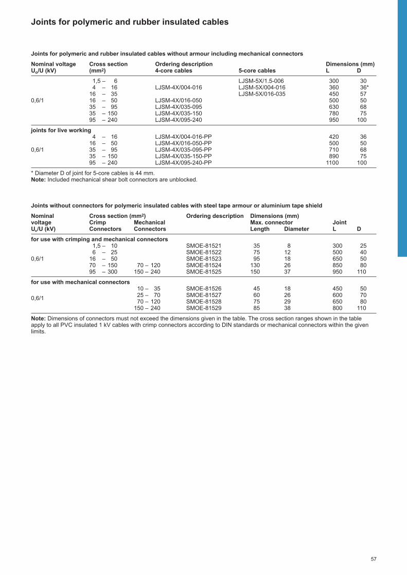
57
Joints for polymeric and rubber insulated cables
Joints for polymeric and rubber insulated cables without armour including mechanical connectors
Nominal voltage Cross section Ordering description Dimensions (mm)Uo/U (kV) (mm2) 4-core cables 5-core cables L D
1,5 – 6 LJSM-5X/1.5-006 300 304 – 16 LJSM-4X/004-016 LJSM-5X/004-016 360 36*
16 – 35 LJSM-5X/016-035 450 570,6/1 16 – 50 LJSM-4X/016-050 500 50
35 – 95 LJSM-4X/035-095 630 6835 – 150 LJSM-4X/035-150 780 7595 – 240 LJSM-4X/095-240 950 100
joints for live working4 – 16 LJSM-4X/004-016-PP 420 36
16 – 50 LJSM-4X/016-050-PP 500 500,6/1 35 – 95 LJSM-4X/035-095-PP 710 68
35 – 150 LJSM-4X/035-150-PP 890 7595 – 240 LJSM-4X/095-240-PP 1100 100
* Diameter D of joint for 5-core cables is 44 mm.Note: Included mechanical shear bolt connectors are unblocked.
Joints without connectors for polymeric insulated cables with steel tape armour or aluminium tape shield
Nominal Cross section (mm2) Ordering description Dimensions (mm)voltage Crimp Mechanical Max. connector JointUo/U (kV) Connectors Connectors Length Diameter L D
for use with crimping and mechanical connectors1,5 – 10 SMOE-81521 35 8 300 256 – 25 SMOE-81522 75 12 500 40
0,6/1 16 – 50 SMOE-81523 95 18 650 5070 – 150 70 – 120 SMOE-81524 130 26 850 8095 – 300 150 – 240 SMOE-81525 150 37 950 110
for use with mechanical connectors10 – 35 SMOE-81526 45 18 450 5025 – 70 SMOE-81527 60 26 600 700,6/170 – 120 SMOE-81528 75 29 650 80
150 – 240 SMOE-81529 85 38 800 110
Note: Dimensions of connectors must not exceed the dimensions given in the table. The cross section ranges shown in the tableapply to all PVC insulated 1 kV cables with crimp connectors according to DIN standards or mechanical connectors within the givenlimits.

58
Dimensions L, D see table
Transition joints for polymeric insulated cables to paper insulated cables
CableThe joints are designed for 4-core paperand polymeric insulated cables with or without armour.For example: N(A)YY, SZAPKOVB,IPO 13, NPO 13, ACHPAbI, АСБУ-АВВГ,YAKY, YKY, YKYFtly, ANKOY, AYKY, PP 00, PP 41, N(A)YBY, IPO 14, NPO 14,N(A)KBA.
Design of jointsThe paper cable is transformed to a quasipolymeric insulated cable with heat-shrinkable oil resistive tubing and a breakout. The connectors are insulatedand sealed with adhesive coated heatshrinkable tubing. The outer protectionand sealing is performed by heat-shrinkable tubing.
�
�
Joints including connectorsThe kit includes a solderless earth and neutral connection system for lead or aluminium sheaths.
Joints without connectors In case of 3-core cables, a separate earthlead has to be soldered to the metalsheath (not provided within the kit).
L
D
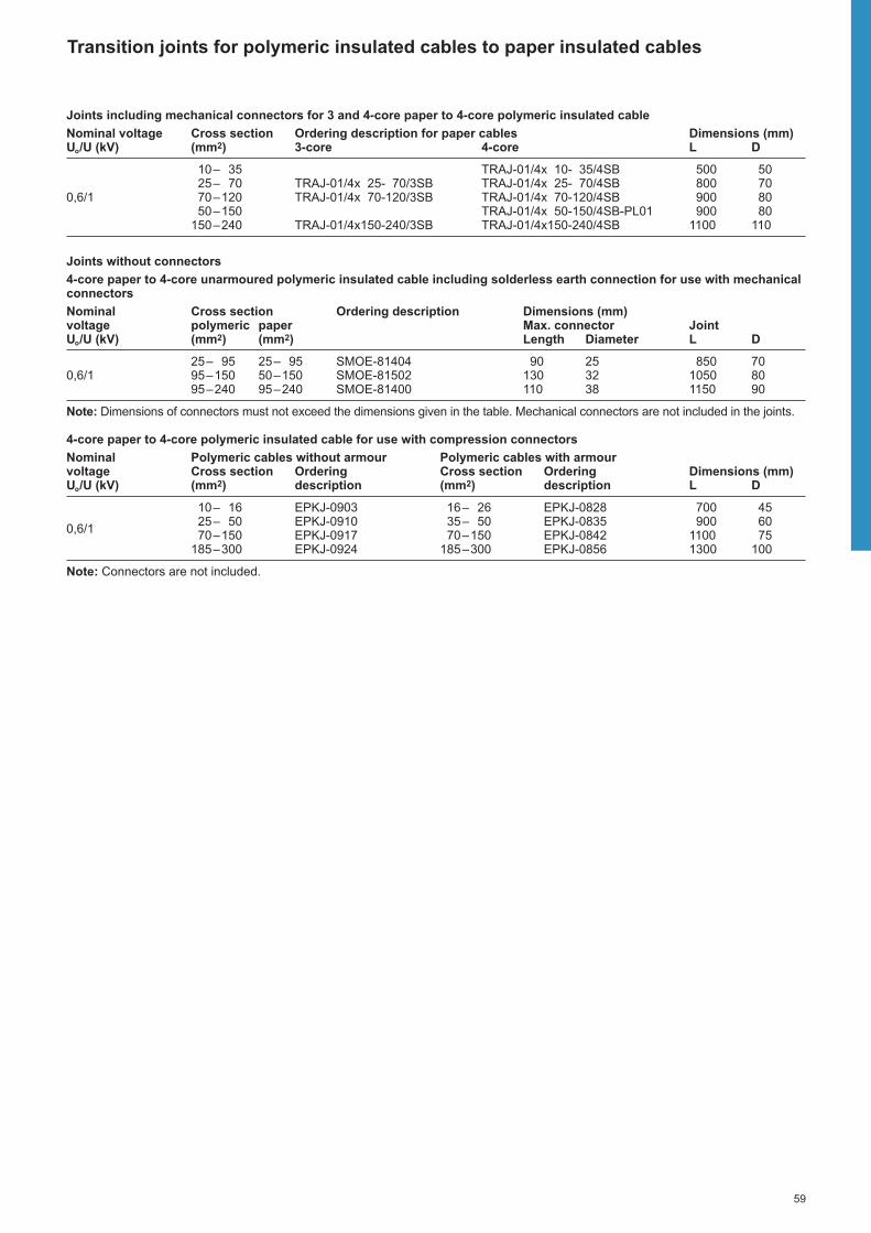
59
Joints including mechanical connectors for 3 and 4-core paper to 4-core polymeric insulated cable
Nominal voltage Cross section Ordering description for paper cables Dimensions (mm)Uo/U (kV) (mm2) 3-core 4-core L D
10– 35 TRAJ-01/4x 10- 35/4SB 500 5025– 70 TRAJ-01/4x 25- 70/3SB TRAJ-01/4x 25- 70/4SB 800 70
0,6/1 70–120 TRAJ-01/4x 70-120/3SB TRAJ-01/4x 70-120/4SB 900 8050–150 TRAJ-01/4x 50-150/4SB-PL01 900 80
150–240 TRAJ-01/4x150-240/3SB TRAJ-01/4x150-240/4SB 1100 110
Joints without connectors
4-core paper to 4-core unarmoured polymeric insulated cable including solderless earth connection for use with mechanicalconnectors
Nominal Cross section Ordering description Dimensions (mm)voltage polymeric paper Max. connector JointUo/U (kV) (mm2) (mm2) Length Diameter L D
25– 95 25– 95 SMOE-81404 90 25 850 700,6/1 95–150 50–150 SMOE-81502 130 32 1050 80
95–240 95–240 SMOE-81400 110 38 1150 90
Note: Dimensions of connectors must not exceed the dimensions given in the table. Mechanical connectors are not included in the joints.
4-core paper to 4-core polymeric insulated cable for use with compression connectors
Nominal Polymeric cables without armour Polymeric cables with armourvoltage Cross section Ordering Cross section Ordering Dimensions (mm)Uo/U (kV) (mm2) description (mm2) description L D
10– 16 EPKJ-0903 16– 26 EPKJ-0828 700 45
0,6/125– 50 EPKJ-0910 35– 50 EPKJ-0835 900 6070–150 EPKJ-0917 70–150 EPKJ-0842 1100 75
185–300 EPKJ-0924 185–300 EPKJ-0856 1300 100
Note: Connectors are not included.
Transition joints for polymeric insulated cables to paper insulated cables

60
Live end seals for polymeric and paper insulated cables
CableThe live end seals are designed forpolymeric or paper insulated cables.For example: SZAMtKAtM, N(A)YY,CYAbY, IPO 13, VVG, AVVG, ААБвУ,АСБУ, AYKY, CYKY, ANKOY, ANKOP,PP 00, XP 00, PP 41, N(A)YBY, IPO 14.
Dimensions L, D see table
Nominal voltage Cross section Ordering description Dimension (mm)Uo/U (kV) (mm2) L D
10– 16 EPKE-0024 90 32
0,6/125– 50 EPKE-0044 90 4270–120 EPKE-0064 143 56
150–300 EPKE-0084 163 67
Design of live end sealThe ends of the cores are sealed andinsulated with heat-shrinkable end caps. A larger end cap protects the cores andseals to the oversheath. For cables with armour an additionalmetallic shielding is available on request.
�
�L
D

61
Joints for flexible, rubber insulated cables
CableThe joints are designed for flexible,rubber insulated cables with or withoutshield. The maximum number of cores isfive.For example: GTB, GTBa, MCCG,H07RN-F, H07RN-FF, KГ, KГН, KПГ,OnG, Ogek, OnGbekz…, CGSG, CGTU,CGGU, CGDU, EpN 53, EpN 55, EpN 61,EpN 62, EpN (BN)76, GN 50.
Dimensions L, D see table
Unshielded flexible cables
Nominal voltage Cross section Ordering description Dimension (mm)Uo/U (kV) (mm2) L D
1,5– 2,5 EMKJ-0002 300 204– 6 EMKJ-0004 350 28
0,6/1 10– 16 EMKJ-0017 510 3425– 50 EMKJ-0027 560 5570–120 EMKJ-0037 740 78
Note: Connectors are not included.
Shielded flexible cables
Nominal voltage Cross section Ordering description Dimension (mm)Uo/U (kV) (mm2) L D
1,5– 2,5 EMKJ-0102 300 204– 6 EMKJ-0104 350 25
0,6/1 10– 16 EMKJ-0117 510 3625– 50 EMKJ-0127 560 6070–120 EMKJ-0137 740 84
Note: Connectors are not included.
Design of jointsThe connectors are insulated and sealedby flexible tubing which is pre-coated witha hot-melt adhesive. The outer protectionand sealing is also performed by flexible,thick-wall heat-shrinkable tubing. Thevoids between the cores and the outertubing are filled by flexible mastic. In caseof shielded cables a copper mesh iswrapped around the mastic.
L
D

62
Joints for polymeric insulated control cables with DuraSeal connectors
CableThe joints are designed for polymericinsulated control cables with or withoutarmour.For example: NYY, KВВГ, KПсВГ, YKSY,YKSYy, YeKSY, CYKY, PP 00.
Dimension L see table
DuraSeal – connector with pre-installedadhesive coated heat shrinkable tubing
Joints for polymeric insulated cables without armour
Nominal voltage Number of Cross section Cable diameter (mm) Ordering description DimensionUo/U (kV) conductors (mm2) min. max. L (mm)
4– 7 1,5–2,5 8 19 SMOE-81140 3008–14 1,5–2,5 12 22 SMOE-81141 300
0,6/1 15–21 1,5–2,5 15 27 SMOE-81142 35022–40 1,5–2,5 20 35 SMOE-81143 35041–75 1,5–2,5 28 44 SMOE-81144 400
Joints for polymeric insulated cables with steel tape armour
Nominal voltage Number of Cross section Cable diameter (mm) Ordering description DimensionUo/U (kV) conductors (mm2) min. max. L (mm)
4– 7 1,5–2,5 17,5 21 SMOE-81140-T 4508–14 1,5–2,5 17,5 26 SMOE-81141-T 450
0,6/1 15–21 1,5–2,5 22 30 SMOE-81142-T 55022–40 1,5–2,5 22 39 SMOE-81143-T 55041–75 1,5–2,5 27 47 SMOE-81144-T 650
Joints for other cable types are available on request.
Design of jointsFor cables without armour The cores are connected and sealed withDuraSeal connectors. A cardboard linerensures a round shape over which theouter protection and sealing is performedby a thick-wall heat-shrinkable tubing.
For cables with steel tape armourThe inner jointing is performed as forcables without armour. In addition, a tinned grid is wrapped around thejointing area and mechanically securedand electrically connected to the steeltape by roll springs. The outer protectionand sealing is performed by a thick-wall,heat-shrinkable tubing.
L

63
Pre-insulated connectors and terminals type DuraSeal
ApplicationProvides an environmentally sealed coreconnection for installation cables. To beused in joints or as a sealed terminal.
ConstructionThe connector consists of a crimp barreland a pre-installed adhesive coated heatshrinkable tubing.
The terminal consists of a crimping lugand a pre-installed adhesive coated heatshrinkable tubing.
InstallationSelect the correct connection element.Remove the core insulation on a length of 7,5 mm. With the adhesive not beingsticky at room temperature, the cores canbe easily inserted into the connector.
Crimp the connector with a suitablecrimping tool, for example AD-1522-1.
Heat the crimped connection area with a hot air tool until the tubing recovers andthe adhesive flows. The heating toolHL2010E-230V-EURO and the reflectorHL1802E-070519 are recommended.
Insulated connectors
Cross section (mm2) Ordering description Colour Lengthmin. max. (mm)
0,5 1 D-406-0001 red 321,5 2,5 D-406-0002 blue 324 6 D-406-0003 yellow 32
Note: To be ordered in boxes, a box contains 100 pcs or 50 pcs (only size 4-6 mm2).
Insulated terminals
Cross section (mm2) Ordering description ColourFork Ring
min. max. d = 4 mm d = 4 mm d = 6 mm d = 8 mm
0,5 1 B-106-2401 B-106-1401 B-106-1601 B-106-1801 red1,5 2,5 B-106-2402 B-106-1402 B-106-1602 B-106-1802 blue4 6 B-106-2403 B-106-1403 B-106-1603 B-106-1803 yellow
Note: d = hole diameter

64
Branch joints for polymeric and paper insulated cables
CableThe joints are designed for 4-core paperand polymeric insulated cables with orwithout armour up to 240 mm2.For example: N(A)YY, SZAPKOVB,IPO 13, NPO 13, ACHPAbI, ВВГ, АВВГ,YAKY, YKY, AKFtA, AYKY, CYKY, ANKOY,ANKOP, PP 00-(A), PP 41-(A), N(A)YBY,IPO 14.
Design of jointsThe joint is designed to be installed liveby using compact ring connectors. Masticaround the cores and the connectorseals and insulates. A fibre reinforcedwraparound seals to the oversheath andprovides mechanical protection. Joints for armoured cables include in additionsolderless earth connections. Papercables are sealed with additional oil-resistive mastic and a breakout for thebranch cable.
Dimensions L, D see table
�
�
Conductors types:sm: Sector strandedse: Sector solidrm: Round strandedre: Round solid
L
D

65
Branch joints for polymeric and paper insulated cables
Heat shrinkable branch joint for 4-core polymeric insulated cables including compact ring connector
Nominal Main conductor Branch conductor Ordering description Dimensionsvoltage rm/sm re/se rm/sm re/se L DUo/U (kV) (mm2) (mm2) (mm2) (mm2) (mm) (mm)
5x 2,5–10 5x 2,5–10 SMOE-81601* 250 504– 16 4– 16 SMOE-81426* 380 55
35– 70 50– 95 6– 50 6– 70 BMHM-1001-4B1-4874 500 13570–120 95–150 6– 50 6– 70 BMHM-1001-4B1-6875 500 135
0,6/1 150 185se 6– 70 6– 70 BMHM-1001-4C1-6878 500 135185 240se 6– 70 6– 70 BMHM-1001-4D1-6879 500 155240sm – 6– 70 6– 70 BMHM-1001-4D1-6880 500 155
95–120 120–15010– 95/ 16–120/
BMHM-1001-4D2-6877 560 15535–120 50–150
* Insulated single core connectors are included.Note: Additional sealing kits for double branches are available on request.
Heat shrinkable branch joint for 3 1/2-core polymeric insulated cables including compact ring connector
Nominal Main cable Branch Ordering description Dimensionsvoltage phase conductor neutral conductor conductor L D
rm/sm re/se rm/sm re/se rm/sm re/seUo/U (kV) (mm2) (mm2) (mm2) (mm2) (mm2) (mm2) (mm) (mm)
70–120 95–150 35–70 50–95 6–50 6–70 BMHM-1001-4B1-4875.3 500 135150sm – 70sm 70 6–50* 6–50 BMHM-1001-4C1-6878.3 500 135
0,6/1 185sm – – 95re 6–50* 6–50 BMHM-1001-4D1-6879.3 500 155240sm – – 120re 6–50* 6–50 BMHM-1001-4D1-6880.3-RE 500 155240sm – 120sm – 6–50* 6–50 BMHM-1001-4D1-6880.3-SM 500 155
* Needs to be rounded for 50 mm2 sm.Note: Additional sealing kits for double branches are available on request.
Heat shrinkable branch joint without connector
Nominal Cross section Ordering description Connector Dimensionsvoltage Main cable Branch cable diameter L DUo/U (kV) (mm2) (mm2) (mm) (mm) (mm)
Branch joints for polymeric insulated cables without armour16–185 6– 95 BMHM-1001-4B1 115 500 135
0,6/1 95–185 6– 95 BMHM-1001-4C1 115 500 13595–240 6– 70 BMHM-1001-4D1 135 500 15595–240 6–150 BMHM-1001-4D2 135 560 155
Branch joints for polymeric insulated cables with steel tape armour or aluminium tape shield16–185 16– 95 BMHM-1031-4C1-CEE01 115 560 135
+ EPPA 206-4-250*0,6/195–185 16– 95 BMHM-1031-4C1-CEE01 115 560 13595–240 50–120 BMHM-1031-4D1-CEE01 135 560 155
Branch joints for paper insulated main cables and polymeric insulated branch cables35– 95 35–95 SMOE-81551 115 560 135
0,6/1 120–185 35–95 SMOE-81503 115 560 135120–240 35–95 SMOE-81740 135 650 155
* EPPA-206-4-250 filler mastic must be used if the cross section is less than 95 mm2.
Compact ring connectors for cross sections up to 240 mm2 are also available separately, see page 73.

66
PowerGel filled joints and repair sleeves for polymeric insulated cables
PowerGel sealing technology products• Quick, easy and clean installation.• Reliable protection against humidity and water.• Suitable for outdoor and direct-buried applications.• Qualified to the international joint standard CENELEC EN50393.• Halogen-free and UV-resistant.• Unlimited shelf life.• Environment friendly and no subject to labeling requirements.
Force
Gel
Surface
Moisture
RayGel Plus: Inline and branch jointsGelBox: Inline joint GelWrap: Inline joint and repair sleeve
CableThe joints are designed for single andmulti-core polymeric insulated cableswithout armour.For example: SZAMtKAtM, KAtM,N(A)YY, N(A)YBY, VVG, AVVG, ÂÂÃ,ÀÂÂÃ, YAKY, YKY, YKYFty, AYKY, CYKY,PP 00, XP 00, PP 41, N(A)YC(W)Y
ApplicationIndoor and outdoor use - to install cableconnections in underground, direct buriedand overhead applications.
Performance testsJoints are qualified to CENELEC EN 50393, the European specification for direct buried applications. This includes a three week heat cycling test with thejoint immersed in 1 meter depth of water.
Design of joints RayGel Plus – inline and branch jointsCable connections are easily establishedby using the universal connector blockwith sliding nuts and insertion tool,included in RayGel Plus 2 and RayGelPlus 3 delivery, or using the connectorsselected according to the max.dimensions given in the tables for RayGelPlus 1 and RayGel Plus 0. The uniqueuniversal connector block provides fullbranch capabilities without cutting of maincables. Installation is very straight forwardas the block snaps into the bottom side of the PowerGel filled enclosure. Theenclosure can be snap-closed by hand,due to its flexible gel barriers. A strainrelief is integrated within the enclosureand quickly installed with the two cableties. No special tools are needed andjoints can be put into service immediately.For branch configurations, the branchcable and cores are positioned in parallelto the main cable and cores.
GelBox – inline joints The cables are connected with a suppliedpiercing shear bolt mechanical connectorblock. Based on the piercing technologyno stripping of the primary insulation isrequired. The connector block will bepositioned in the middle of the PowerGelfilled half shells. Both shells are easilysnapped in to each other. Accidentally re-opening is prevented by the snap in mechanism.
GelWrap - inline joints GelWrap sleeves are simply wrappedaround and snapped on any cable in thegiven application range and completelyencapsulate the connection withoutentering of moisture into a splice.GelWrap sleeves can be used also for insulation and cable jacket repair.
“Hydrophobic” action of PowerGelsealant.

67
PowerGel filled joints and repair sleeves for polymeric insulated cables
GelBox inline joints with insulation piercing mechanical shear bolt connectors for cables with up to 5 cores
Nominal Cross section Ordering description Dimensions Voltage Length x Width x HeightUo/U (kV) (mm2) (mm)
4 x 6 – 25 (35*) GelBox-25 270 x 100 x 450,6/1 5 x 6 – 16** GelBox-25-5 270 x 100 x 45
5 x 10 – 25** GelBox-25-5/25 270 x 100 x 45
* 35 mm2 with cable insulation removed (non-piercing application).** Includes a single mantle clamp for the earthing wire.
RayGel Plus inline and branch joints with universal connector block for cables with up to 5 cores
Nominal Cross section Ordering description Dimensions Voltage Main Branch Length x Width x HeightUo/U (kV) (mm2) (mm2) (mm)
0,6/13 – 5 x 1,5 – 6 3 – 5 x 1,5 – 6 RayGel Plus 2 233 x 78 x 403 – 5 x 6 – 16 3 – 5 x 6 – 16 RayGel Plus 3 313 x 90 x 47
RayGel Plus inline and branch joints without connector for cables with up to 5 cores
Nominal Cross section Ordering description Dimensions (mm)voltage Main Branch Length x Width x HeightUo/U (kV) (mm2) (mm2) Connectors, max. Joint
0,6/12 – 3 x 1,5 – 2,5* 2 – 3 x 1,5* RayGel Plus 0 26 x 24 x 16 100 x 37 x 243 – 5 x 1,5 – 2,5* 3 – 5 x 1,5* RayGel Plus 1 26 x 38 x 16 139 x 51 x 24
* Cross section for 1-core cables: main 1 x 10 – 50 mm2, branch 1 x 10 – 16 mm2.
GelWrap inline joints without connector for single-core cables and repair sleeve for cable cores and cable oversheaths
Nominal Cable diameter Ordering description Max. length voltage Connector or oversheath repairUo/U (kV) (mm) (mm)
4 – 18 GELWRAP-18/4-150 744 – 18 GELWRAP-18/4-200 1244 – 18 GELWRAP-18/4-250 174
0,6/110 – 33 GELWRAP-33/10-150 4810 – 33 GELWRAP-33/10-200 9810 – 33 GELWRAP-33/10-250 14820 – 50 GELWRAP-50/20-250 10020 – 50 GELWRAP-50/20-300 150

68
GUROFLEX filled joints up to 240 mm2 for polymeric insulated cables
CableThe joints are designed for 3-, 3,5-, 4-and 5-core polymeric insulated cableswithout armour up to 240 mm2.For example: SZAMtKAtM, KAtM,N(A)YY, N(A)YBY, VVG, AVVG, ВВГ,АВВГ, YAKY, YKY, YKYFty, AYKY, CYKY,PP 00, XP 00, PP 41, N(A)YC(W)Y.
GUROFLEX filled inline joints including connector block
Nominal voltage Cable diameter Cross section Ordering description Joint (mm)*Uo/U (kV) (mm) (mm2) L H
13 – 20 5 x 1,5 – 6 BV-0-GD-KS0 220 730,6/1 16 – 25 5 x 6 – 16 BV-1-GD-KS1 230 80
21 – 30 4 x 16 – 25 BV-2-GD-KS2 270 90
* L = Overall length of the housing; H = Overall height of the housing.Note: Cross sections are selected according to dimensions given in CENELEC HD 603.
The BV joints without connector block are available on request.
GUROFLEX filled inline joints without connector
Nominal voltage Cable diameter Cross section Ordering description Joint (mm)*Uo/U (kV) (mm) (mm2) L H
6 – 19 4 x 1,5 – 6 PXE-SU1-GD 160 366 – 27 4 x 1,5 – 10 PXE-SU2-GD 190 48
14 – 34 4 x 2,5 – 5 x 16 PXE-SU3-GD 240 500,6/1 16 – 37 4 x 4 – 25 PXE-SU4-GD 270 65
20 – 44 4 x 10 – 50 PXE-SU5-GD 360 8026 – 52 4 x 25 – 95 PXE-SU6-GD 430 9535 – 67 4 x 70 – 150** PXE-SU7-GD 530 120
* L = Overall length of the housing; H = Overall height of the housing.** For crimp connectors up to 240 mm².Note: Cross sections are selected according to dimensions given in CENELEC HD 603.
GUROFLEX filled joints for other cable types and cross sections are available on request.
Kit content of PXE-SUx-GDPXE joint without connectorBV joint including connector block
Design of joints Including connector blockThe joints consist of a shock-resistant,transparent polycarbonate snap-to-closedesign housing and integrated polymerfoams for sealing. The robust housing iseasy and quickly to assemble, cutting to the cable diameter is not needed. TheGUROFLEX filler material is delivered in a double chamber bag. For details on GUROFLEX filler see page 71. Theinline connector block with integratedspacing and insulation allows a quick and easy connection. A cable diameterrange from 13 - 30 mm can be covered.The cable can be energized immediatelyafter joint installation.
Without connectorsThe joints include joint shells, two-partGUROFLEX filler material in a doublechamber bag, core separator, abrasivecloth tape and sealant tape.The clear, robust, snap to close jointshells ensure an easy positioning andfilling.During an installation the joint shells aretrimmed to suit the cable size andconductors jointed by connectors (not partof the kit). The core separator is placedbetween the connectors, the joint shellsare snapped closed and their ends sealedby the included tape. The final step of theinstallation is mixing and pouringGUROFLEX filler material. For details on GUROFLEX filler see page 71.The cable can be energized immediatelyafter joint installation.
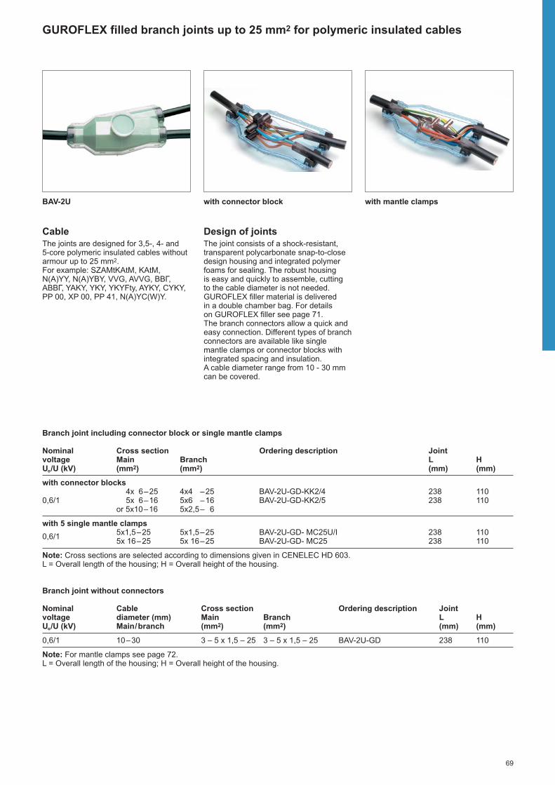
69
GUROFLEX filled branch joints up to 25 mm2 for polymeric insulated cables
BAV-2U with connector block with mantle clamps
CableThe joints are designed for 3,5-, 4- and 5-core polymeric insulated cables withoutarmour up to 25 mm2.For example: SZAMtKAtM, KAtM,N(A)YY, N(A)YBY, VVG, AVVG, ВВГ,АВВГ, YAKY, YKY, YKYFty, AYKY, CYKY,PP 00, XP 00, PP 41, N(A)YC(W)Y.
Design of joints The joint consists of a shock-resistant,transparent polycarbonate snap-to-closedesign housing and integrated polymerfoams for sealing. The robust housing is easy and quickly to assemble, cuttingto the cable diameter is not needed.GUROFLEX filler material is delivered in a double chamber bag. For details on GUROFLEX filler see page 71.The branch connectors allow a quick andeasy connection. Different types of branchconnectors are available like singlemantle clamps or connector blocks withintegrated spacing and insulation. A cable diameter range from 10 - 30 mmcan be covered.
Branch joint including connector block or single mantle clamps
Nominal Cross section Ordering description Jointvoltage Main Branch L HUo/U (kV) (mm2) (mm2) (mm) (mm)
with connector blocks4x 6–25 4x4 –25 BAV-2U-GD-KK2/4 238 110
0,6/1 5x 6–16 5x6 –16 BAV-2U-GD-KK2/5 238 110or 5x10–16 5x2,5– 6
with 5 single mantle clamps5x1,5–25 5x1,5–25 BAV-2U-GD- MC25U/I 238 1100,6/15x 16–25 5x 16–25 BAV-2U-GD- MC25 238 110
Note: Cross sections are selected according to dimensions given in CENELEC HD 603.L = Overall length of the housing; H = Overall height of the housing.
Branch joint without connectors
Nominal Cable Cross section Ordering description Jointvoltage diameter (mm) Main Branch L HUo/U (kV) Main/branch (mm2) (mm2) (mm) (mm)
0,6/1 10–30 3 – 5 x 1,5 – 25 3 – 5 x 1,5 – 25 BAV-2U-GD 238 110
Note: For mantle clamps see page 72.L = Overall length of the housing; H = Overall height of the housing.

70
GUROFLEX filled branch joints 35 mm2 to 240 mm2 for polymeric insulated cables
MM 5, MM 7 BAV-C5, BAV-C7 Compact ring connector
CableThe joints are designed for 4-corepolymeric insulated cables without armourup to 240 mm2.For example: SZAMtKAtM, KAtM,N(A)YY, N(A)YBY, VVG, AVVG, ВВГ,АВВГ, YAKY, YKY, YKYFty, AYKY, CYKY,PP 00, XP 00, PP 41, N(A)YC(W)Y.
Design of joints The joints consist of impact-resistant,transparent polypropylene snap-to-closedesign (MM 5, MM 7) or impact-resistant,transparent polycarbonate snap-to-closedesign (BAV) housings and polymerfoams for sealing. The housings are easyand quick to assemble, no adjustment to the cable diameter needed. Joints areavailable with compact ring connectors.The GUROFLEX filler materialis delivered in double chamber bag (D)or in cans (C). The joints allow filling in different positions. A cable diameterrange from 27–65 mm can be covered.
Conductors types:sm: Sector strandedse: Sector solidrm: Round strandedre: Round solid
Branch joints including compact ring connector
Nominal Cross section (mm2) Ordering description Jointvoltage Main Branch Length HeightUo/U (kV) rm, sm / re, se rm, sm / re, se (mm) (mm)
35– 70/ 50– 95 6– 50 / 6– 70 MM-5-GD170-4874 295 17570–120/ 95–150 6– 50 / 6– 70 MM-5-GD170-6875 295 175
0,6/1 240sm/ – 6– 70 / 6– 70 MM-7-GC490-6880 480 23095–120/ 120–150 10– 95rm/ 16–120re MM-7-GC490-6877 480 230
35–120sm/ 50–150se
Branch joints without connectors
Nominal Cable Connector Cross section Ordering description Jointvoltage diameter (mm) diameter Main Branch Length HeightUo/U (kV) Main / branch max. (mm) (mm2) (mm2) (mm) (mm)
27 – 55 / 16 – 36 105 4x 35 – 150 4x6 – 70 MM-5-GD170 295 175
0,6/127 – 55 / 16 – 36 140 4x 35 – 150 4x6 – 70 BAV-C5-GD375 440 20537 – 60 / 16 – 57 140 4x120 – 240 4x6 – 150 MM-7-GC490 480 23045 – 65 / 16 – 50 140 4x120 – 240 4x6 – 150 BAV-C7-GC570 484 212
Note: Selecting criteria are cable diameters and connector sizes. Cross sections are selected for cables according to CENELEC HD 603 used with compact ring connectors. For compact ring connectors see page 73.
GUROFLEX filled joints for other cable types and cross sections are available on request.

71
GUROFLEX - two-component environmental friendly filler material
Two-component GUROFLEX in doublechamber bag
Two-component GUROFLEX in cans Joint filled with “green” GUROFLEX
PropertiesGUROFLEX is an environmental friendly,easy to handle, two-component, coldcasting material based on hydrocarbonresins. GUROFLEX can be used for allself-supporting underground cable jointsystems up to 1kV. GUROFLEX issuitable for XLPE, PE, PVC and paperinsulated cables. GUROFLEX hasexcellent insulating properties, ishydrophobic and gives excellent corrosionprotection. GUROFLEX filler can behandled without any special safetyprecautions and allows installation at low temperatures.
HandlingThe resin is available either in doublechamber bags or in cans. Preparation of GUROFLEX system takes placeimmediately before casting. The twocomponents are mixed either in a doublechamber bag or in the larger of twocomponent cans to start the cross-linkingprocess. Mixing takes about 3 minutesand can be aided by the use of a powerdriven stirrer. No ‘topping-up’ is neededand the equipment can be energizedimmediately after filling. The joint trenchcan be backfilled immediately after filling.
Technical data• Dielectric strength: Ud > 10 kV/mm• Spec. Dielectric Constant: εr ~ 4• Specific Vol. Resistance: QD > 1013 Ωcm• Relative Density: ρ = 1,22 g/cm3
• Min. Storage temperature: –20 °C• Min. Installation temperature: –10 °C• Hardness Shore A: ~ 20• Shelf life: 2 years @ 23 °C• Color: Green
Ordering description for supply in Volume Weight Quantities suitable Double chamber bags Cans (~ l ) (~ kg) for joints
GUROFLEX-D035 – 0,35 0,43 BV-0, BV-1GUROFLEX-D055 – 0,55 0,67 BV-2GUROFLEX-D080 – 0,8 0,98 BAV-2GUROFLEX-D140 – 1,4 1,71 MM-5GUROFLEX-D160 GUROFLEX-C160 1,6 1,95 VMY-405, MM-5GUROFLEX-D170 GUROFLEX-C170 1,7 2,07 MM-5GUROFLEX-D215 GUROFLEX-C215 2,15 2,75 BAV-5GUROFLEX-D245 GUROFLEX-C245 2,45 2,99 –– GUROFLEX-C385 3,85 4,84 BAV-C5– GUROFLEX-C490 4,9 5,98 VMP-600, MM-7– GUROFLEX-C570 5,7 6,95 BAV-C7, MM-7
Note: Volume and weight are absolute value of both components together. Other quantities available on request.

72
Mantle Clamps
Universal mantle clamp with individualbranch connection and insulation cap
Mantle clamp with insulation cap Mantle clamp without insulation cap
Universal mantle clamp with individual branch connection and insulation cap
Cross section (mm2) Ordering description Quantity in setMain Branch (pcs)
GURO-MC25U-I-3 3
2,5 – 25 1,5 – 25 GURO-MC25U-I-4 4
GURO-MC25U-I-5 5
Mantle clamps with common connection with insulation cap
Combinations of cross sections (mm2) Ordering description Quantity in setMain Branch (pcs)
4 – 6 1,5 – 6 GURO-MC06-I-4 4
2,5 – 6 2,5 – 6 GURO-MC06-I-5 5
16 1,5 – 16 GURO-MC16-I-4 4 10 – 16 2,5 – 10
GURO-MC16-I-5 56 – 16 4 – 6
25 2,5 – 25 GURO-MC25-I-4 4 16 – 25 6 – 16
GURO-MC25-I-5 510 – 25 10
Mantle clamps with common connection without insulation cap
Combinations of cross sections (mm2) Ordering description Quantity in setMain Branch (pcs)
25 2,5 – 25 GURO-MC25-5 5 16 – 25 6 – 16
GURO-MC25-20-INT 2010 – 25 10
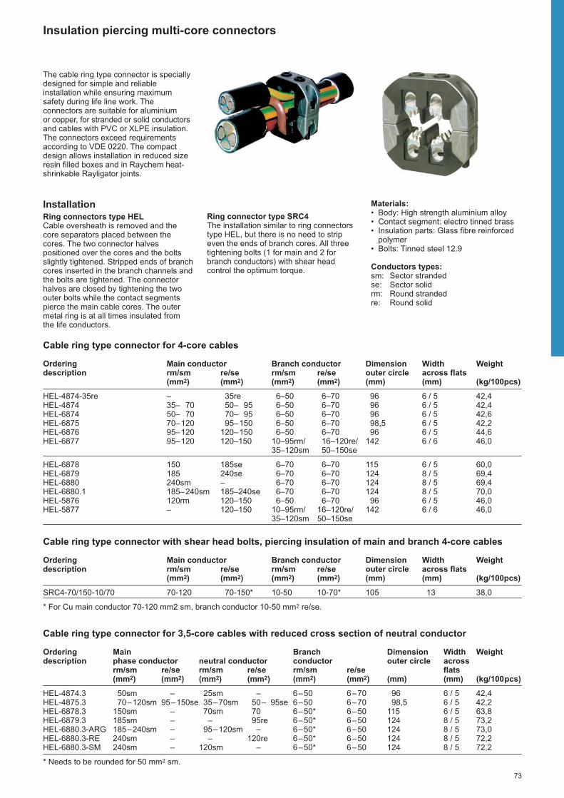
73
Insulation piercing multi-core connectors
The cable ring type connector is speciallydesigned for simple and reliableinstallation while ensuring maximumsafety during life line work. Theconnectors are suitable for aluminium or copper, for stranded or solid conductorsand cables with PVC or XLPE insulation.The connectors exceed requirementsaccording to VDE 0220. The compactdesign allows installation in reduced sizeresin filled boxes and in Raychem heat-shrinkable Rayligator joints.
InstallationRing connectors type HEL Cable oversheath is removed and thecore separators placed between thecores. The two connector halvespositioned over the cores and the boltsslightly tightened. Stripped ends of branchcores inserted in the branch channels andthe bolts are tightened. The connectorhalves are closed by tightening the twoouter bolts while the contact segmentspierce the main cable cores. The outermetal ring is at all times insulated from the life conductors.
Materials:• Body: High strength aluminium alloy• Contact segment: electro tinned brass• Insulation parts: Glass fibre reinforced
polymer• Bolts: Tinned steel 12.9
Conductors types:sm: Sector strandedse: Sector solidrm: Round strandedre: Round solid
Ring connector type SRC4The installation similar to ring connectorstype HEL, but there is no need to stripeven the ends of branch cores. All threetightening bolts (1 for main and 2 forbranch conductors) with shear headcontrol the optimum torque.
Cable ring type connector for 4-core cables
Ordering Main conductor Branch conductor Dimension Width Weightdescription rm/sm re/se rm/sm re/se outer circle across flats
(mm2) (mm2) (mm2) (mm2) (mm) (mm) (kg/100pcs)
HEL-4874-35re – 35re 6–50 6–70 96 6 / 5 42,4HEL-4874 35– 70 50– 95 6–50 6–70 96 6 / 5 42,4HEL-6874 50– 70 70– 95 6–50 6–70 96 6 / 5 42,6HEL-6875 70–120 95–150 6–50 6–70 98,5 6 / 5 42,2HEL-6876 95–120 120–150 6–50 6–70 96 6 / 5 44,6HEL-6877 95–120 120–150 10–95rm/ 16–120re/ 142 6 / 6 46,0
35–120sm 50–150se
HEL-6878 150 185se 6–70 6–70 115 6 / 5 60,0HEL-6879 185 240se 6–70 6–70 124 8 / 5 69,4HEL-6880 240sm – 6–70 6–70 124 8 / 5 69,4HEL-6880.1 185–240sm 185–240se 6–70 6–70 124 8 / 5 70,0HEL-5876 120rm 120–150 6–50 6–70 96 6 / 5 46,0HEL-5877 – 120–150 10–95rm/ 16–120re/ 142 6 / 6 46,0
35–120sm 50–150se
Cable ring type connector with shear head bolts, piercing insulation of main and branch 4-core cables
Ordering Main conductor Branch conductor Dimension Width Weightdescription rm/sm re/se rm/sm re/se outer circle across flats
(mm2) (mm2) (mm2) (mm2) (mm) (mm) (kg/100pcs)
SRC4-70/150-10/70 70-120 70-150* 10-50 10-70* 105 13 38,0
* For Cu main conductor 70-120 mm2 sm, branch conductor 10-50 mm2 re/se.
Cable ring type connector for 3,5-core cables with reduced cross section of neutral conductor
Ordering Main Branch Dimension Width Weightdescription phase conductor neutral conductor conductor outer circle across
rm/sm re/se rm/sm re/se rm/sm re/se flats(mm2) (mm2) (mm2) (mm2) (mm2) (mm2) (mm) (mm) (kg/100pcs)
HEL-4874.3 50sm – 25sm – 6–50 6–70 96 6 / 5 42,4HEL-4875.3 70–120sm 95–150se 35–70sm 50– 95se 6–50 6–70 98,5 6 / 5 42,2HEL-6878.3 150sm – 70sm 70 6–50* 6–50 115 6 / 5 63,8HEL-6879.3 185sm – – 95re 6–50* 6–50 124 8 / 5 73,2HEL-6880.3-ARG 185–240sm – 95–120sm – 6–50* 6–50 124 8 / 5 73,0HEL-6880.3-RE 240sm – – 120re 6–50* 6–50 124 8 / 5 72,2HEL-6880.3-SM 240sm – 120sm – 6–50* 6–50 124 8 / 5 72,2
* Needs to be rounded for 50 mm2 sm.

74
Med
ium
Vol
tage
Joi
nts

75
Joints – Medium Voltage
Joints for belted or screened, 3-core paper insulatedcables with one common metal sheath 6 kV, 10 kV, 15 kV, 20 kV and 35 kV 76
Joints for screened, paper insulated cables with one metal sheath per phase 10 kV, 15 kV, 20 kV and 35 kV 78
Repair joints for paper insulated cables 6 kV, 10 kV, 15 kV and 20 kV 80
Joints for unscreened, 3-core polymeric insulated cables 6 kV and 10 kV 82
Joints for screened flexible, rubber insulated cables and transition joints to 3-core unscreened polymeric insulated cables 6 kV 83
Joints and repair joints for screened, 3-core polymericinsulated cables 10 kV, 15 kV, 20 kV and 35 kV 84
Joints and repair joints for screened, 1-core polymeric insulated cables 10 kV, 15 kV, 20 kV and 35 kV 86
Pre-expanded elastomeric inline joints for screened, 1 core polymeric insulated cables10 kV, 15 kV, 20 kV and 35 kV 88
Branch joints for screened, 1-core polymeric insulated cables 10 kV, 15 kV and 20 kV 90
Live end seals for screened, 1-core polymeric insulatedcables 10 kV, 15 kV, 20 kV and 35 kV 91
Transition joints for polymeric insulated cables to 3-core belted or screened, paper insulated cableswith one common metal sheath 6 kV, 10 kV, 15 kV,20 kV and 35 kV 92
Transition joints for screened polymeric insulated cables to screened, paper insulated cables with one metal sheath per phase 10 kV, 15 kV, 20 kV and 35 kV 94

76
Joints for belted or screened, 3-core paper insulated cables with one common metalsheath 6 kV, 10 kV, 15 kV, 20 kV and 35 kV
CableThe joints are designed for 3-core beltedor screened paper insulated (MI, MIND)cables 6 kV, 10 kV, 15 kV, 20 kV and 35 kVwith a common metal sheath.For example: ACHPAbI, N(A)KBA, SB,ASB, SAAB, AABY, ASBY, СБ, АСБУ,ААБУ, ААШв, АСБ-В, KftA, Akny,HAKnFtA, HknFty, Hkny, CMKOPV,CMKOY, AMKOY, ANKOPY, IPO 13,NPO 13, IPHO 13, NPHO 13, N(A)HKBA.
Design of jointsFor belted cablesThe paper cores are covered with oilbarrier tubing. The crutch is filled with a stress grading, oil resistive yellow mastic.The mechanical connectors, supplied withthe joint, are covered with a stress controlpatch. The primary insulation over theconnectors is provided with provenadhesive coated, heat-shrinkable tubing.The area between and around the coresis filled with a cold applied mastic which is
Belted or screened cable
Belted cable
�
�
fully compatible with the materials used toimpregnate paper cables. Heat-shrinkabletubing seals to the metal sheath andensures during installation that the masticflows and fills any void. Solderless earthconnection and metal tape replace themetal sheath and armour in the joint. Anouter heat-shrinkable tubing provides theouter sealing and protection.
For belted or screened cablesThe paper cores are completely coveredwith oil barrier tubing and from the crutcharea to the screen end with conductivetubing. The crutch area is filled with a stress grading, oil resistive yellowmastic and sealed with an adhesive lined,conductive breakout which is installedover the cores and the end of the metalsheath. Thus the paper cable is transformed to a quasi polymeric cable construction andthe cables jointed similarly. At the end ofthe conductive tubing and over the
Dimensions L, D see table
connectors stress grading mastic isapplied. The jointing area of each cablecore is covered with heat-shrinkablestress control tubing. Heat-shrinkabletriple-extruded elastomeric joint bodyprovides the correct thickness ofinsulation and the screening over theinsulation. Copper mesh wrapped aroundthe joint area rebuilds the metallic screen. The metal sheath and armour are jointedwith solderless connections. The armouris replaced by a metal case or a metaltape. The outer sealing and protection isperformed by adhesive coated, thick-wallheat-shrinkable tubing.The joints are designed to allow crossingof cable cores. Joints types GUSJ aresupplied with mechanical connectors,joints type EPKJ are supplied withoutconnectors.
L
D
3SB 3SB
3SB 3SB

77
Joints including mechanical connectors
Joints for belted paper insulated cables 6 kV, 10 kV and 20 kV
Nominal voltage Cross section Ordering description Dimensions (mm)Uo/U (kV) (mm2) L D
25– 50 GUSJ-12/ 35- 50 1050 903,5/6 70–120 GUSJ-12/ 70-120 1250 120
150–240 GUSJ-12/150-240 1250 140
25– 50 GUSJ-12/ 35- 50 1050 906/10 70–120 GUSJ-12/ 70-120 1250 120
150–240 GUSJ-12/150-240 1250 140
8,7/1570–150 GUSJ-24/ 70-150-3SB 1800 130
120–240 GUSJ-24/120-240-3SB 1800 150
12/2070–150 GUSJ-24/ 70-150-3SB 1800 130
120–240 GUSJ-24/120-240-3SB 1800 150
Joints without connectors
Joints for screened or belted paper insulated cables 10 kV, 20 kV and 35 kV
Nominal voltage Cross section Ordering description Dimensions (mm)Uo/U (kV) (mm2) L D
35– 70 EPKJ-17A/3SB-3SB-T 2500 1106/10 95–185 EPKJ-17B/3SB-3SB-T 2500 130
240–400 EPKJ-17C/3SB-3SB-T 2500 160
25– 50 EPKJ-17A/3SB-3SB-T 2500 1108,7/15 70–150 EPKJ-17B/3SB-3SB-T 2500 130
185–300 EPKJ-17C/3SB-3SB-T 2500 160
35– 70 EPKJ-24B/3SB-3SB-T 2500 11012/20 95–240 EPKJ-24C/3SB-3SB-T 2500 130
300–400 EPKJ-24D/3SB-3SB-T 2500 160
50– 70 EPKJ-36A/3SB-3SB-T 2500 11020/35 95–150 EPKJ-36B/3SB-3SB-T 2500 130
185–400 EPKJ-36C/3SB-3SB-T 2500 160
Note: The joints are designed for crimp connectors. Connectors are not included in the joints.
Joints for belted or screened, 3-core paper insulated cables with one common metalsheath 6 kV, 10 kV, 20 kV and 35 kV

78
Joints for screened, paper insulated cables with one metal sheath per phase 10 kV, 15 kV, 20 kV and 35 kV
CableThe joints are designed for single or 3-core, screened, paper insulated (MI,MIND) cables 10 kV, 15 kV, 20 kV and35 kV with one metal sheath per phase.For example: ACHPAbI, NAHKBA, AOSB,OSB-V, AOSB, OSB, AVVB, AVVG,APVG, ОСБ-В, АОСБ, ОСБ, Hkny,HAKny, CNKOY, ANKOY, ANKTOYPV,AMKTOYPV, IPZO 13, NPZO 13,N(A)EKBA, N(A)KLEY.
Dimensions L, D see table
3-core paper insulated cable
�
�
Design of jointsFor three-core cables a solderless earthconnection provides the connectionbetween the armour and the metalsheaths. Heat-shrinkable breakouts andtubing seal and protect the metal sheaths.A stress grading, oil resistive yellowmastic is laid around the end of the metalsheath and the paper cores are completelycovered with oil barrier tubing. A shortconductive tubing rebuilds the screenfrom the metal sheath to the coveredpaper core.Thus the paper cable is transformed to a quasi polymeric cable construction andthe cables are jointed similarly. At the endof the conductive tubing and over theconnectors stress grading mastic isapplied. The jointing area of each cablecore is covered with heat-shrinkablestress control tubing. Heat-shrinkabletriple-extruded elastomeric joint bodyprovides the correct thickness of insula -tion and the screening over the insulation.Copper mesh wrapped around the jointarea rebuilds the metallic screen. The metal sheaths are jointed with solder-less connections. For three core cablesthe armour is replaced by a metal tape.The outer sealing and protection isperformed by adhesive coated, thick-wallheat-shrinkable tubing for single corecables and by a fibre-reinforced wrap -around for 3-core cables.Joints type GUSJ are supplied withmechanical connectors, joints type RPKJand EPKJ are supplied withoutconnectors.
L
D
3HL 3HL

79
Joints for screened, paper insulated cables with one metal sheath per phase 10 kV, 15 kV, 20 kV and 35 kV
Joints including mechanical connectors
Joints for three core cables with steel tape armour
Nominal voltage Cross section Ordering description Dimensions (mm)Uo/U (kV) (mm2) L D
25– 70 GUSJ-24/ 25- 70-3HL 1600 906/10 70–150 GUSJ-24/ 70-150-3HL 1600 120
120–240 GUSJ-24/120-240-3HL 1600 140
25– 70 GUSJ-24/ 25- 70-3HL 1600 908,7/15 70–150 GUSJ-24/ 70-150-3HL 1600 120
120–240 GUSJ-24/120-240-3HL 1600 140
25– 70 GUSJ-24/ 25- 70-3HL 1600 9012/20 70–150 GUSJ-24/ 70-150-3HL 1600 120
120–240 GUSJ-24/120-240-3HL 1600 140
35– 50 GUSJ-42/ 35- 50-3HL 2000 12020/35 70–120 GUSJ-42/ 70-120-3HL 2000 130
120–240 GUSJ-42/120-240-3HL 2000 150
Joints for single core cables without armour
Nominal voltage Cross section Ordering description Dimensions (mm)Uo/U (kV) (mm2) L D
25– 70 GUSJ-24/ 25- 70-1HL 700 6012/20 70–150 GUSJ-24/ 70-150-1HL 700 70
120–240 GUSJ-24/120-240-1HL 700 80
35– 50 GUSJ-42/ 35- 50-1HL 1000 7020/35 70–120 GUSJ-42/ 70-120-1HL 1000 80
120–240 GUSJ-42/120-240-1HL 1000 90
Joints without connectors
Joints for three core cables with steel tape armour
Nominal voltage Cross section Ordering description Dimensions (mm)Uo/U (kV) (mm2) L D
35– 70 RPKJ-24A/3HL-3HL-T-CEE01 1900 906/10 95–185 RPKJ-24B/3HL-3HL-T-CEE01 1900 130
185–300 RPKJ-24C/3HL-3HL-T-CEE01 1900 160
25– 50 RPKJ-24A/3HL-3HL-T-CEE01 1900 908,7/15 70–150 RPKJ-24B/3HL-3HL-T-CEE01 1900 130
150–300 RPKJ-24C/3HL-3HL-T-CEE01 1900 160
25– 95 RPKJ-24B/3HL-3HL-T-CEE01 1900 9012/20 95–240 RPKJ-24C/3HL-3HL-T-CEE01 1900 130
240–400 RPKJ-24D/3HL-3HL-T-CEE01 1900 160
50– 70 EPKJ-36A/3HL-3HL-T 2250 9020/35 95–150 EPKJ-36B/3HL-3HL-T 2250 130
185–400 EPKJ-36C/3HL-3HL-T 2250 160
Note: The joints are designed for crimp connectors. Connectors are not included in the joints.
Joints for single core cables without armour
Nominal voltage Cross section Ordering description Dimensions (mm)Uo/U (kV) (mm2) L D
35– 70 EPKJ-17A/1HL-1HL 850 606/10 95–185 EPKJ-17B/1HL-1HL 950 70
240–400 EPKJ-17C/1HL-1HL 950 80
35– 70 EPKJ-24B/1HL-1HL 850 7012/20 95–240 EPKJ-24C/1HL-1HL 950 80
300–400 EPKJ-24D/1HL-1HL 950 90
50– 70 EPKJ-36A/1HL-1HL 1050 7020/35 95–150 EPKJ-36B/1HL-1HL 1050 80
185–400 EPKJ-36C/1HL-1HL 1050 90
Note: The joints are designed for crimp connectors. Connectors are not included in the joints.
Joints for other cable types, cross sections and voltage classes are available on request.

80
Repair joints for paper insulated cables 6 kV, 10 kV and 20 kV
CableThe repair joints are designed for singleor 3-core belted or screened, paperinsulated (MI, MIND) cables 6 kV, 10 kV,15 kV and 20 kV.For example:ACHPAbI, N(A)KBA, SB, ASB, SAAB,AABY, ASBY, СБ, АСБУ, ААБУ, ААШв,АСБ-В, KftA, Akny, HAKnFtA, HknFty,Hkny, CMKOPV, CMKOY, AMKOY,ANKOPY, IPO 13, NPO 13, IPHO 13,NPHO 13, N(A)HKBA
ACHPAbI, NAHKBA, AOSB, OSB-V,AOSB, OSB, AVVB, AVVG, APVG, ОСБ-В, АОСБ, ОСБ, Hkny, HAKny, CNKOY,ANKOY, ANKTOYPV, AMKTOYPV, IPZO13, NPZO 13, N(A)EKBA, N(A)KLEY
Belted or screened, 3-core paperinsulated cable with one common metalsheath
3SB 3SB
Design of jointsThe design and components of the repairjoint is very similar to the relevant inlinejoint. The longer length of the repair jointallows cut the damaged part out of thecable and replace it by includedmechanical repair connector. This allowsrepairing the cable for a length of up to320 mm.
Max. length of repair
Mechanical repair connector• a tin plated aluminium alloy body• torque-controlled shear head bolts• inserts for small conductor sizes
Screened, 3-core paper insulated cablewith one metal sheath per phase
3HL 3HL
Screened, single core paper insulatedcable without armour
1HL 1HL
max. 320 mm
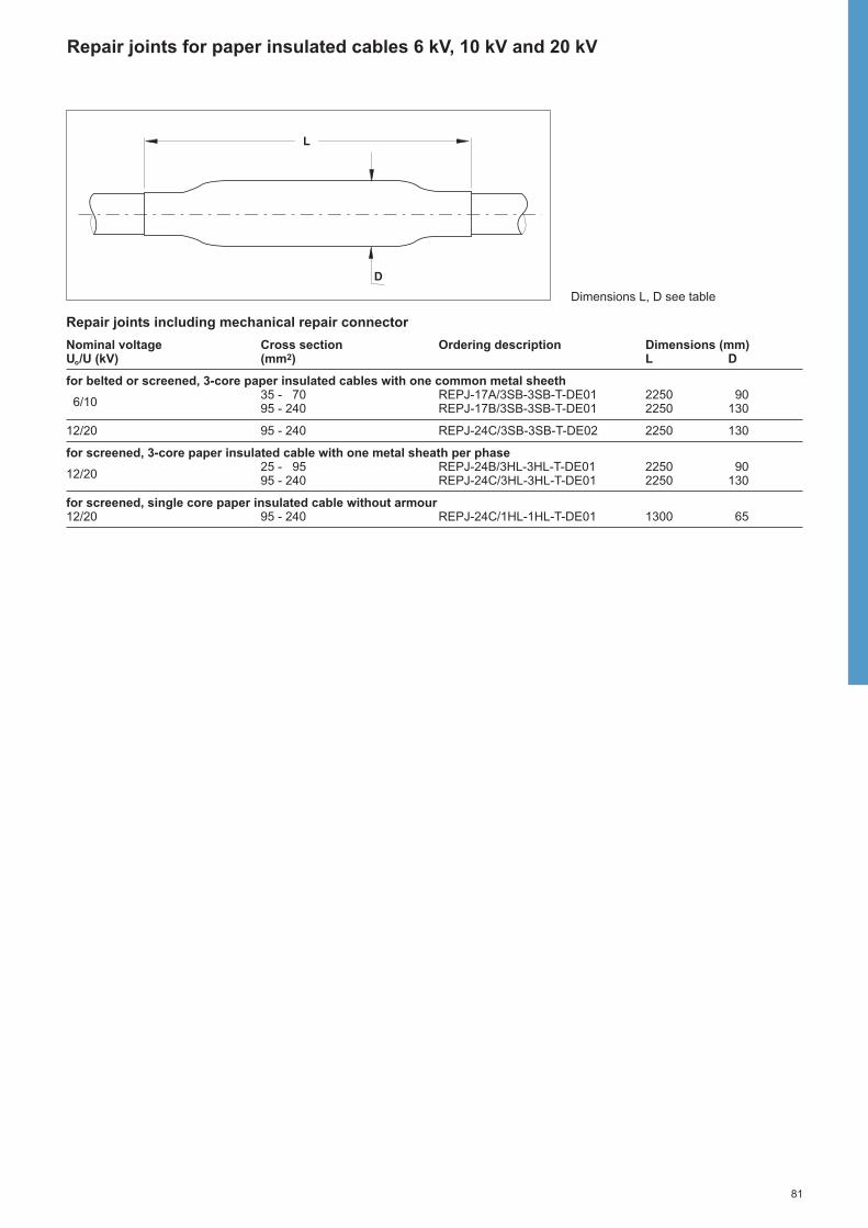
81
Repair joints for paper insulated cables 6 kV, 10 kV and 20 kV
Repair joints including mechanical repair connector
Nominal voltage Cross section Ordering description Dimensions (mm)Uo/U (kV) (mm2) L D
for belted or screened, 3-core paper insulated cables with one common metal sheeth
6/1035 - 70 REPJ-17A/3SB-3SB-T-DE01 2250 9095 - 240 REPJ-17B/3SB-3SB-T-DE01 2250 130
12/20 95 - 240 REPJ-24C/3SB-3SB-T-DE02 2250 130
for screened, 3-core paper insulated cable with one metal sheath per phase
12/2025 - 95 REPJ-24B/3HL-3HL-T-DE01 2250 9095 - 240 REPJ-24C/3HL-3HL-T-DE01 2250 130
for screened, single core paper insulated cable without armour12/20 95 - 240 REPJ-24C/1HL-1HL-T-DE01 1300 65
Dimensions L, D see table
�
�L
D

82
Joints for unscreened, 3-core polymeric insulated cables 6 kV and 10 kV
Joints type POLJ are supplied withmechanical connectors, joints type EPKJand SMOE are supplied without connectors.
Design of transition joints to 1-core screened polymericinsulated cablesThe cores of the screened cable arecovered with yellow void filling mastic andheat-shrinkable stress control tubing. Theconductors are jointed with a mechanicalconnector supplied with the joint. Theconnection area is covered with a stresscontrol patch. Heat-shrinkable triple-extruded elastomeric joint body providesthe correct thickness of insulation and thescreening over the insulation. Theshielding is rebuilt with copper mesh anda solderless earth connection systemprovides the electrical connection. Theouter sealing and protection is performedby adhesive coated, thick-wall heat-shrinkable tubing.
CableThe joints are designed for 3-coreunscreened, polymeric insulated cables 6 kV and 10 kV with common copper tapeor wire shield or with steel tape armour.For example: PP 41(A), PP 44(A), PP45(A), NAYFGY, AВВБ, AВВГ, AПВГ,YKYFtly, YKYFoy, YAKY, YKYFtly,YKYFoy, YAKY, YKY…, AYKCYDY,AYKCY, N(A)YBY, N(A)YGY
Joints including mechanical connectors
Joints for cables with common copper tape or wire shield or with steel tape armour
Nominal voltage Cross section Ordering description Dimensions (mm)Uo/U (kV) (mm2) L D
25– 50 POLJ-06/3x 25- 50 1200 703,5/6 70–120 POLJ-06/3x 70-120 1200 90
150–240 POLJ-06/3x150-240 1200 100
25– 50 POLJ-06/3x 25- 50 1200 706/10 70–150 POLJ-06/3x 70-120 1200 90
120–240 POLJ-06/3x150-240 1200 100
Transition joints for 3-core unscreened cables to 1-core screened cables including mechanical connectors
Nominal voltage Cross section (mm2) Ordering description Dimensions (mm)Cable type
Uo/U (kV) 3-core 1-core* L D
25– 70 25– 70 POLJ-12/1x 25- 70-3U 800 903,5/6 70–120 70–150 POLJ-12/1x 70-150-3U 800 90
150–240 150–240 POLJ-12/1x150-240-3U 800 100
25– 70 25– 70 POLJ-12/1x 25- 70-3U 800 906/10 70–120 70–150 POLJ-12/1x 70-150-3U 800 90
120 –240 150–240 POLJ-12/1x150-240-3U 800 100
* Application ranges apply for 10 kV and 20 kV cables
Joints without connectors
Cables with armour
Nominal voltage Cross section Ordering description for cables Dimensions (mm)Uo/U (kV) (mm2) with tape armour with wire armour L D
3,5/6 16– 70 EPKJ-2079-J41 EPKJ-2079 800 75and 95–150 EPKJ-2080-J42 EPKJ-2080 1000 1056/10 185–300 EPKJ-2081-J43 EPKJ-2081 1200 135
Cables with common copper tape shield and without armour
Nominal voltage Cross section Ordering description Dimensions (mm)Uo/U (kV) (mm2) L D
25– 70 SMOE-62096 800 703,5/6 95– 185 SMOE-62095 1000 90
240 SMOE-61302 1200 100
Design of jointsThe connectors are insulated and sealedwith thick-wall, heat-shrinkable tubing andmastic. The armour or copper tapeshielding is rebuilt with a wraparoundmetal case or with copper mesh. A solderless earth connection providesthe electrical connection to the armour or copper shielding. The outer protectionand sealing is performed by adhesivecoated heat-shrinkable tubing.

83
Joints for screened, flexible, rubber insulated cables and transition joints to 3-coreunscreened polymeric insulated cables 6 kV
CableThe joints are designed for screened,flexible, rubber insulated cables 6 kVwith one or three earth cores.For example: EpN 64 i 65, EPN (BN) 64 i 74, NTSCE, NTSCGEWÖU, КГЭ, КГЭT, Ogb, Ogc z YKY, YKY…, CBVU, CHCU,EpN(BN) 76 i 78, EpN(BN) 78/53.
Dimensions L, D see table
Joints for flexible rubber insulated cables without connectors
Cables with 3 earth cores Cables with 1 earth coreNominal voltage Cross section Ordering Cross section Ordering Dimensions (mm)Uo/U (kV) (mm2) description (mm2) description L D
10/ 10 EMKJ-2001 750 553,5/6 25/10– 95/16 EMKJ-2201-CEE01 16/ 16– 95/ 95 EMKJ-2011 750 100
120/16–185/35 EMKJ-2211-CEE01 120/120–185/185 EMKJ-2021 950 130
Note: The joints are designed for crimp connectors of maximal length 60 mm.
Transition joints for flexible rubber insulated cables to unscreened polymeric insulated cables 6 kV without connectors
Nominal voltage Cross section Ordering description Dimensions (mm)Uo/U (kV) (mm2) L D
3,5/6 70–185 SMOE-62453 1000 130
Design of joints for flexiblecablesThe connector areas are stress-graded,sealed and insulated with a void filler tapeand thick-wall heat-shrinkable tubing. A semiconductive tape rebuilds the screenover the insulating tubing. The outersealing and protection is performed byflexible, abrasive resistant, thick-walltubing. The voids between the cores andthe outer tubing are filled by flexiblemastic.
��������������������������������
L
D
Design of transition joints forflexible cables to unscreenedpolymeric insulated cablesThe cores of the flexible cable are stressgraded at the end of the screen with a mastic tape. The connectors areinsulated and sealed with thick-wall,adhesive coated, heat-shrinkable tubing.The shielding is rebuilt with copper meshand a solderless earth connectionprovides the electrical connection to theshielding. The outer protection andsealing is performed by adhesive coated,heat-shrinkable tubing.

84
Joints and repair joints for screened, 3-core polymeric insulated cables 10 kV, 15 kV, 20 kV and 35 kV
CableThe joints are designed for 10 kV, 15 kV,20 kV and 35 kV screened, three corepolymeric insulated cables with or withoutarmour.For example: SzAQkrKVM, XHP 81,CEYSEAbY, ACYSEAbY, CYSEY, ACYSEY, ВВГ, АВБвШв, АВВГ, YHAKXS,XUHAKXS..., AXEKVCY, CXEKVCY,AXEKVCEY, CXEKVCY, N(A)2XSY,EpHP 81, PHP 48, PHP 84, XHP 48,N(A)YSEY.
Dimensions L, D see table
Design of joints withmechanical connectorsFor cables with wire or tape screenAt the screen end yellow void fillingmastic is applied and the cable end iscovered with a heat-shrinkable stresscontrol tubing. The conductors are jointedwith a mechanical connector suppliedwith the joint. The connection area iscovered with a stress control patch. Heat-shrinkable triple-extruded elasto mericjoint body provides the correct thicknessof insulation and the screening over theinsulation. Copper mesh wrapped aroundthe joint area rebuilds the metallic screen.For cables with wire screen a mechanicalconnector is supplied with the kit. Forcables with tape screen the joint includesa solderless earth connec tion system. For cables with armour a metal case or a metal tape provides additionalmechanical protection. The outer sealingand protection is performed by adhesivecoated, thick-wall heat-shrinkable tubing.
Additional sealing kit for transitionjoints of 3-core to 1-core cablesThe transition joint is built the same wayas an inline joint for 3-core cables. A heat-shrinkable breakout ensures the sealingof the outer tubing to the 1-core cables. A solderless earth connection systemallows the connection of all typicalcombinations of shied constructions.
Design of joints withoutconnectorsFor cables with wire or tape screen At the screen end and over theconnectors yellow void filling mastic isapplied. The jointing area of each cablecore is covered with heat-shrinkablestress control tubing. Heat-shrinkableelastomeric tubing provides the correctthickness of insulation and the screeningover the insulation. Copper meshwrapped around the joint area rebuildsthe metallic screen. For cables with tapescreen the joint includes a solderlessearth connection. For cables with armoura metal case or a metal tape providesadditional mechanical protection. Theouter sealing and protection is performedby adhesive coated, thick-wall heat-shrinkable tubing.
Design of repair jointsThe design and components of the repairjoint and the inline joint are similar. Thelonger length of the repair joint allows cutthe damaged part out of the cable andreplace it by a piece of cable core andtwo connectors. This allows repairing thecable for a length of up to 520 mm (seealso drawing page 86).
Design of transition joints for 3-core to1-core cables
The transition joint is built the same wayas an inline joint for 3-core cables.Special sealing clips ensure the sealingof the outer tubing to the 1-core cables.
L
D

85
Joints and repair joints for screened 3-core polymeric insulated cables 10 kV, 15 kV, 20 kV and 35 kV
Joints including mechanical connectors
For cables with wire or metal tape screenNominal Cross Ordering description Dimensions (mm)voltage section Cable without Cable withUo/U (kV) (mm2) armour steel tape armour steel wire armour L D
25– 70 POLJ-12/3x 25- 70 POLJ-12/3x 25- 70-T POLJ-12/3x 25- 70-W 1100 806/10 70–150 POLJ-12/3x 70-150 POLJ-12/3x 70-150-T POLJ-12/3x 70-150-W 1100 90
120–240 POLJ-12/3x120-240 POLJ-12/3x120-240-T POLJ-12/3x120-240-W 1100 100
8,7/15 25– 70 POLJ-24/3x 25- 70 POLJ-24/3x 25- 70-T 1250 90and 70–150 POLJ-24/3x 70-150 POLJ-24/3x 70-150-T 1250 100
12/20 120–240 POLJ-24/3x120-240 POLJ-24/3x120-240-T 1250 110
20/3570–120 POLJ-42/3x 70-120 POLJ-42/3x 70-120-T POLJ-42/3x 70-120-W 2200 150
120–240 POLJ-42/3x120-240 POLJ-42/3x120-240-T POLJ-42/3x120-240-W 2200 180
Note: The application ranges are defined for cables with round, stranded conductors; for cables with sector shaped or solidconductors contact your TE Energy products’ representative.
Additional sealing kit for transition joints of 3-core to 1-core cablesNominal voltage Cross section Ordering descriptionUo/U (kV) (mm2)
6/10, 8,7/15, 12/20 25–240 SMOE-62800
Note: For joints to cables with aluminium laminate (e.g. type AHXAMK-W) the solderless ground wire connection kit SMOE-62600must be ordered separately (details see page 93).
Joints without connectors
Joints for three core cables without armourNominal voltage Cross section Ordering description for cables Dimensions (mm)Uo/U (kV) (mm2) with wire shield with metal tape shield L D
10– 25 SXSU-4302-CEE04 1450 90 25– 35 SXSU-4302 SXSU-4302-CEE01 1450 90
6/10 50– 70 SXSU-4312 SXSU-4312-CEE01 1450 90 95–185 SXSU-4322 SXSU-4322-CEE01 1450 100
240–300 SXSU-4332 SXSU-4332-CEE01 1500 110
35– 50 SXSU-4312 SXSU-4312-CEE01 1450 90 8,7/15 70–150 SXSU-4322 SXSU-4322-CEE01 1450 100
185–300 SXSU-4332 SXSU-4332-CEE01 1500 110
10– 70 SXSU-5312 1450 90 35– 95 SXSU-5322 1500 10012/2095–240 SXSU-5332 1500 110
300 SXSU-5342 1500 110
Repair joints for three core cables without armour Nominal voltage Cross section Ordering description for cables Dimension (mm)Uo/U (kV) (mm2) with wire shield with metal tape shield L D
35– 95 REPJ-12A/3XU REPJ-12A/3XU-CEE01 2000 906/10 120–185 REPJ-12B/3XU REPJ-12B/3XU-CEE01 2000 100
240–400 REPJ-12C/3XU REPJ-12C/3XU-CEE01 2100 110
25– 50 REPJ-24A/3XU 2000 9012/20 70–120 REPJ-24B/3XU 2000 100
150–240 REPJ-24C/3XU 2100 110
Joints for three core cables with armourNominal voltage Cross section Ordering description for cables Dimension (mm)Uo/U (kV) (mm2) with wire armour with tape armour L D
25– 35 SXSW-4304 SXST-4303-CEE01 1450 100
6/10 50– 70 SXSW-4314 SXST-4313-CEE01 1500 10095–185 SXSW-4324 SXST-4323-CEE01 1600 150
240–300 SXSW-4334 SXST-4333-CEE01 1600 180
Transition joints for three core to one core polymeric insulated cableNominal voltage Cross section Ordering description Dimension (mm)Uo/U (kV) (mm2) L D
35– 70 EPKJ-17A/1XU-3XU 1000 906/10 95–185 EPKJ-17B/1XU-3XU 1100 130
240–400 EPKJ-17C/1XU-3XU 1100 160
35– 70 EPKJ-24B/1XU-3XU 1100 9012/20 95–240 EPKJ-24C/1XU-3XU 1100 130
300–400 EPKJ-24D/1XU-3XU 1100 160
Joints for other cable types, cross sections or voltage classes are available on request.

86
Joints and repair joints for screened, 1-core polymeric insulated cables 10 kV, 15 kV, 20 kV and 35 kV
CableThe joints are designed 10 kV, 15 kV,20 kV and 35 kV screened one corepolymeric insulated cables.For example: A2YSb(r)Y, A2YSY, ПвП,АПвП, ВПвП, YHAKXS, XUHAKXS,XUHKXS, AXEKVCEY, CXEKVCEY,N(A)2XSY, SAXKA, DISTRI, XHE 49(A),XHP 48(A), EHP 48(A), N(A)2XS(F)2Y,AHXAMK-W, NFC 33-223.
Design of joints withmechanical connectorsFor cables with wire or tape screenAt the screen end yellow void fillingmastic is applied and the cable end iscovered with a heat-shrinkable stresscontrol tubing. The conductors are jointedwith a mechanical connector suppliedwith the joint. The connection area iscovered with a stress control patch. Heat-shrinkable triple-extruded elastomericjoint body provides the correct thickness
of insulation and the screening over theinsulation. Copper mesh wrapped aroundthe joint area rebuilds the metallic screen.For cables with wire screen an earthconnection system is supplied with the kit.For cables with tape screen the jointincludes a solderless earth connectionsystem which is also suitable for cableswith alu minium laminate (e.g. typeAHXAMK-W). The outer sealing andprotection is performed by an adhesivecoated, thick-wall, heat-shrinkable tubing.
For cables with aluminium wire screenThe inner components of the cable upto the bedding are rebuilt as for cableswith wire or tape screen. The aluminiumwires are connected with mechanicalconnectors and covered with metal tape.The outer sealing and protection isperformed by an adhesive coated, thick-wall, heat-shrinkable tubing.
Design of joints withoutconnectorsFor cables with wire or tape screenAt the screen end and over the connectoryellow, void filling mastic is applied. Theentire joint area is covered with heat-shrinkable stress control tubing. Heat-shrinkable triple-extruded elastomericjoint body provides the correct thicknessof insulation and the screening over theinsulation. Copper mesh wrapped aroundthe joint area rebuilds the metallic screen.For cables with tape screen the jointincludes a solderless earth connectionsystem which is also suitable for cableswith aluminium laminate (e.g. typeAHXAMK-W). The outer sealing andprotection is performed by adhesivecoated, thick-wall heat-shrinkable tubing.
Design of repair joints
The design and components of the repairjoint and the inline joint are similar. Thelonger length of the repair joint allows cutthe damaged part out of the cable andreplace it by a piece of cable core and twoconnectors. This allows repairing the cablefor a length of up to 520 mm (10 kV and20 kV) or 420 mm (35 kV).
Repair joint
Joint
Dimensions L, D see table
L
D
520

87
Joints and repair joints for screened, 1-core polymeric insulated cables 10 kV, 15 kV, 20 kV and 35 kV
Joints including mechanical connectors
For cables with wire or metal tape screen
Nominal voltage Cross section Ordering description for cables Dimensions (mm)Uo/U (kV) (mm2) with wire shield with tape or wire shield * L D
25– 70 POLJ-12/1x 25- 70 POLJ-12/1x 25- 70-CEE01 550 4570–150 POLJ-12/1x 70-150 POLJ-12/1x 70-150-CEE01 550 55
120–240 POLJ-12/1x120-240 POLJ-12/1x120-240-CEE01 550 656/10 240–400 POLJ-12/1x240-400 – 650 75
500 POLJ-12/1x500 – 700 85630 POLJ-12/1x630 – 700 85800 POLJ-12/1x800 – 700 90
25– 70 POLJ-24/1x 25- 70 POLJ-24/1x 25- 70-CEE01 550 55
8,7/1570–150 POLJ-24/1x 70-150 POLJ-24/1x 70-150-CEE01 600 65
and120–240 POLJ-24/1x120-240 POLJ-24/1x120-240-CEE01 600 70
12/20240–400 POLJ-24/1x240-400 – 650 80500 POLJ-24/1x500 – 800 90630 POLJ-24/1x630 – 800 90
35– 70 POLJ-42/1x 35- 70 POLJ-42/1x 35- 70-CEE01 750 6570–120 POLJ-42/1x 70-120 POLJ-42/1x 70-120-CEE01 750 70
20/35120–240 POLJ-42/1x120-240 POLJ-42/1x120-240-CEE01 750 75300–400 POLJ-42/1x300-400 – 800 85500 POLJ-42/1x500 – 900 95630 POLJ-42/1x630 – 900 95
* The joints are designed for cables with copper tape shield or with aluminium laminate (e.g. type AHXAMK-W) and can also be usedfor cables with wire shields. For transitions of cables with wire shield to cables with Al-laminate use joints for cables with wire shield.
For cables with aluminium wire armour and wire or tape screen
Nominal voltage Cross section Ordering description Dimensions (mm)Uo/U (kV) (mm2) L D
25– 70 POLJ-12/1x 25- 70-AW 850 506/10 70–150 POLJ-12/1x 70-150-AW 850 60
120–240 POLJ-12/1x120-240-AW 900 70
8,7/15 25– 70 POLJ-24/1x 25- 70-AW 900 60and 70–150 POLJ-24/1x 70-150-AW 900 7012/20 120–240 POLJ-24/1x120-240-AW 900 75
20/3570–120 POLJ-42/1x 70-120-AW 1250 75
120–240 POLJ-42/1x120-240-AW 1250 80
Repair Joint for cables with wire or tape screen
Nominal voltage Cross section Ordering description Max. repair length Dimensions (mm)Uo/U (kV) (mm2) (mm2) (mm2) (mm) L D
6/10 kV 8,7/15 kV 12/20 kV6/10, 8,7/1525– 70 25– 70 25– 70 REPJ-24/1x 25- 70 520 1200 50and95–150 70–150 70–120 REPJ-24/1x 70-150 520 1200 5512/20
150–240 120–240 120–240 REPJ-24/1x120-240 520 1200 70
20/3570–120 REPJ-42/1x 70-120 420 1200 55
120–240 REPJ-42/1x120-240 420 1200 70
Joints without connectors for cables with wire or tape screen
Nominal voltage Cross section Ordering description for cables with Dimensions (mm)Uo/U (kV) (mm2) (mm2) wire shield metal tape shield * L D
6/10 kV 8,7/15 kV50– 70 35– 50 SXSU-4111 SXSU-4111-CEE01 550 456/1095– 185 70–120 SXSU-4121 SXSU-4121-CEE01 600 55and
185– 300 150–240 SXSU-4131 SXSU-4131-CEE01 650 658,7/15400– 630 300–500 SXSU-4141 SXSU-4141-CEE01 750 75800–1200 630–800 SXSU-4151 750 85
25– 95 SXSU-5121 SXSU-5121-CEE01 600 60
12/2095– 240 SXSU-5131 SXSU-5131-CEE01 650 70
240– 500 SXSU-5141 750 80630– 800 SXSU-5151 750 85
35– 150 SXSU-6122 850 6520/35 150– 300 SXSU-6132 850 70
400– 630 SXSU-6142 950 80
* The joints are designed for cables with copper tape shield or with aluminium laminate (e.g. type AHXAMK-W).
Joints for other cable types, cross sections or voltage classes are available on request. Joints for 1-core cables include material for 1 phase.

88
Pre-expanded elastomeric inline joints for screened, 1-core polymeric insulatedcables 10 kV, 15 kV, 20 kV and 35 kV
CableThe joints are designed for 10 kV, 15 kV,20 kV and 35 kV screened single corepolymeric insulated cables.For example: AXEKVCE(Y), AXEKVCEz,CXEKVCE(Y), (A)2XS(F)2Y, SAXKA,DISTRI, AHXAMK-W, XHE 49, XHP 48,EHP 48.
Joints with pre-installed metallic screeningand oversheath tubing
Dimensions L, D see table
L
D
Design of jointwith pre-installed metallic screeningand oversheath tubing All key components (joint body, thecopper braid and outer tubing) are pre-expanded on one spiral holdout, whichresults in a very short parking lengthduring cable preparation and offers a fast and easy-to-install system.The conductors are jointed by a mechanical connector supplied with the joint. Electrical stress control over the screencut area is provided by conductive conesintegrated in the silicone joint body withan exactly defined geometrical design.The electrical stress control of theconnector area is made with an integratedconductive shield performing as a faradaycage. Screening over the insulation is partof the joint body as well.The silicone rubber joint body shrinksonto the insulation upon removal of thespiral holdout. The copper braid coverscable metallic screen with cross sectionsup to 70 mm2 and it is flipped back to thecable shield and connected by rollsprings. This solderless earth connectionsystem is suitable for cables with wire ortape screen and for aluminium laminatecables as well (e.g. type AHXAMK-W).The flipped backs of the pre-installedouter tubing are rolled out on the cablejacket wrapped up with the mastic. Theouter tubing builds up a reliable moistureseal and corrosion protection.
with separate metallic screening andouter heat-shrinkable, thick-wall re-jacketing tubingThe conductors are jointed by a mechanical connector supplied with the joint. Electrical stress control over the screencut area is provided by conductive conesintegrated in the silicone joint body withan exactly defined geometrical design.The joint body is pre-expanded anddelivered on a spiral holdout system. Thejoint body recovers onto the insulationupon removal of the spiral holdout. The electrical stress control of theconnector area is made with an integratedconductive shield performing as a faradaycage. Screening over the insulation is partof the joint body as well. Copper mesh wrapped around the jointarea rebuilds the metallic screen.An earth connection system, for cableswith wire screen, is supplied with the kit.For cables with tape screen the jointincludes a solderless earth connectionsystem which is also suitable for cableswith aluminium laminate (e.g. typeAHXAMK-W).The outer sealing and protection isperformed by heat-shrinkable, thick-wallre-jacketing tubing with adhesive.
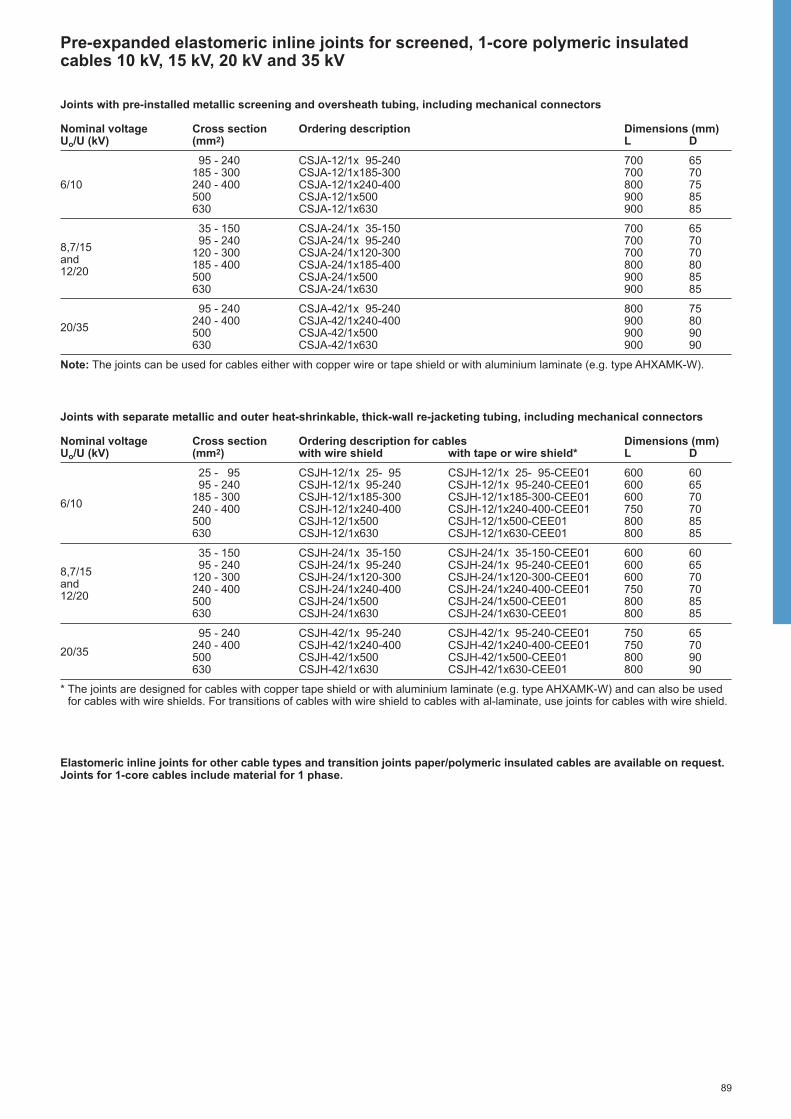
89
Pre-expanded elastomeric inline joints for screened, 1-core polymeric insulatedcables 10 kV, 15 kV, 20 kV and 35 kV
Joints with pre-installed metallic screening and oversheath tubing, including mechanical connectors
Nominal voltage Cross section Ordering description Dimensions (mm)Uo/U (kV) (mm2) L D
95 - 240 CSJA-12/1x 95-240 700 65185 - 300 CSJA-12/1x185-300 700 70
6/10 240 - 400 CSJA-12/1x240-400 800 75500 CSJA-12/1x500 900 85630 CSJA-12/1x630 900 85
35 - 150 CSJA-24/1x 35-150 700 65
8,7/1595 - 240 CSJA-24/1x 95-240 700 70
and120 - 300 CSJA-24/1x120-300 700 70
12/20185 - 400 CSJA-24/1x185-400 800 80500 CSJA-24/1x500 900 85630 CSJA-24/1x630 900 85
95 - 240 CSJA-42/1x 95-240 800 75
20/35240 - 400 CSJA-42/1x240-400 900 80500 CSJA-42/1x500 900 90630 CSJA-42/1x630 900 90
Note: The joints can be used for cables either with copper wire or tape shield or with aluminium laminate (e.g. type AHXAMK-W).
Joints with separate metallic and outer heat-shrinkable, thick-wall re-jacketing tubing, including mechanical connectors
Nominal voltage Cross section Ordering description for cables Dimensions (mm)Uo/U (kV) (mm2) with wire shield with tape or wire shield* L D
25 - 95 CSJH-12/1x 25- 95 CSJH-12/1x 25- 95-CEE01 600 6095 - 240 CSJH-12/1x 95-240 CSJH-12/1x 95-240-CEE01 600 65
6/10185 - 300 CSJH-12/1x185-300 CSJH-12/1x185-300-CEE01 600 70240 - 400 CSJH-12/1x240-400 CSJH-12/1x240-400-CEE01 750 70500 CSJH-12/1x500 CSJH-12/1x500-CEE01 800 85630 CSJH-12/1x630 CSJH-12/1x630-CEE01 800 85
35 - 150 CSJH-24/1x 35-150 CSJH-24/1x 35-150-CEE01 600 60
8,7/1595 - 240 CSJH-24/1x 95-240 CSJH-24/1x 95-240-CEE01 600 65
and120 - 300 CSJH-24/1x120-300 CSJH-24/1x120-300-CEE01 600 70
12/20240 - 400 CSJH-24/1x240-400 CSJH-24/1x240-400-CEE01 750 70500 CSJH-24/1x500 CSJH-24/1x500-CEE01 800 85630 CSJH-24/1x630 CSJH-24/1x630-CEE01 800 85
95 - 240 CSJH-42/1x 95-240 CSJH-42/1x 95-240-CEE01 750 65
20/35240 - 400 CSJH-42/1x240-400 CSJH-42/1x240-400-CEE01 750 70500 CSJH-42/1x500 CSJH-42/1x500-CEE01 800 90630 CSJH-42/1x630 CSJH-42/1x630-CEE01 800 90
* The joints are designed for cables with copper tape shield or with aluminium laminate (e.g. type AHXAMK-W) and can also be usedfor cables with wire shields. For transitions of cables with wire shield to cables with al-laminate, use joints for cables with wire shield.
Elastomeric inline joints for other cable types and transition joints paper/polymeric insulated cables are available on request. Joints for 1-core cables include material for 1 phase.

90
Branch joints for screened, 1-core polymeric insulated cables 10 kV, 15 kV and 20 kV
Based on the well proven technology ofmedium voltage joints, Raychem offers a technically and commercially interestingsolution to realise branch joints for singlecore polymeric insulated cables. A newlydeveloped, mechanical connectorintegrated in the joint design allows a quick, simple and reliable installation.The branch joint is fully qualified to theRaychem test norm PPS 3013.
CableThe branch joint is designed for screened,single core polymeric insulated cables 10 kV and 20 kV.For example: NAYSY, NA2XS2Y, ПвП,АПвП, YHKXS, YHAKXS, XUHAKXS,AXEKVCY, CXEKVCEY, N(A)2XSY,XHE 49(A), XHP 48(A), EHP 48,N(A)2XS(F)2Y.
Design of branch jointsThe cables are prepared as for inlinejoints. Before connecting the cables, thescreen cut is covered with the yellowstress grading filler and stress controltubing. The three cable ends areconnected with a Raychem designedmechanical connector with shear-headbolts. Special moulded parts ensure thefilling and sealing between the branchcables. Following, similar parts as forinline joints are used: Yellow, void fillerover the connector, stress control tubingand a triple-extruded elastomeric jointbody. Copper mesh and a mechanicalconnector for the screen wires re-establish the metallic screen. The outersealing is provided by heat-shrinkable,thick-wall tubing and a 2-finger breakout.All connectors are supplied with the kit.
Dimensions L, D see table
Branch joint for cables with wire screen, including mechanical connectors
Nominal voltage Cross section Ordering description Dimension (mm)Uo/U (kV) (mm2) L D
35– 95 EPKB-12A/1XU-2XU 550 806/10 95–150 EPKB-12B/1XU-2XU 600 90
185–300 EPKB-12C/1XU-2XU 650 95
35– 95 EPKB-24A/1XU-2XU 550 808,7/15 95–150 EPKB-24B/1XU-2XU 600 90
185–300 EPKB-24C/1XU-2XU 650 95
35– 95 EPKB-24A/1XU-2XU 550 80
12/2095–150 EPKB-24B/1XU-2XU 600 90
120–240* EPKB-24C/1XU-2XU-BR02 650 95185–300 EPKB-24C/1XU-2XU 650 95
* for 240 mm2 main cables to branch cable 120 mm2
Branch joints for other cable types and cross sections are available on request. Joints for 1-core cables include material for 1 phase.
L
D

91
Live end seals for screened, 1-core polymeric insulated cables 10 kV, 15 kV, 20 kVand 35 kV
CableThe live end seals are designed for 10 kV,15 kV, 20 kV and 35 kV screened singlecore plastic insulated cables with wire ortape shield.For example: AXEKVCE(Y), AXEKVCEz,CXEKVCE(Y), N(A)2XSY, N(A)2XS(F)2Y,SAXKA, DISTRI, AHXAMK-W.
Design of end sealThe cable is prepared the same way as forjoints including mechanical connector. A polypropylene insulation rod is insertedinto one connector entry instead of a core of the second cable in case of jointing. Thearea over the screen cut and between theend of the core insulation and the rod arewrapped with yellow, stress grading filler.Similar to medium voltage joints, heat-shrinkable stress control tubing and triple-extruded elastomeric joint body are shrunkover the cable end and the insulating rod.The copper mesh is applied around the jointarea to re-establish the metallic screen. Theouter sealing and protection is achieved bythick-wall, adhesive coated heat-shrinkabletubing.
Dimensions L, D see table
Live end seal for single core polymeric insulated cables with wire or tape screen, including mechanical connector
Nominal voltage Cross section Ordering description Diameter over core Dimensions (mm)Uo/U (kV) (mm2) insulation (mm) L D
95 - 240 MXSE-3131 17,6 – 29,4 600 556/10 240 - 400 MXSE-3141 25,7 – 32,6 650 65
500 MXSE-3151 33,8 – 37,2 650 70
95 - 240 MXSE-5131 21,9 – 33,6 600 6012/20 240 - 400 MXSE-5141 29,9 – 38,8 700 70
500 MXSE-5151 37,2 – 41,6 700 75
95 - 240 MXSE-6131 27,8 – 37,6 700 7520/35 240 - 400 MXSE-6141 36,2 – 42,8 750 80
500 MXSE-6151 40,1 – 46,6 800 90
End seals for other cross sections, voltages and cable types are available on request.
L
D

92
Transition joints for polymeric insulated cables to 3-core belted or screened, paperinsulated cables with one common metal sheath 6 kV, 10 kV, 15 kV, 20 kV and 35 kV
CableThe joints are designed for 3-core beltedor screened paper insulated (MI, MIND)cables with a common metal sheath toscreened one or three core polymericinsulated cables 6 kV, 10 kV, 15 kV, 20 kVand 35 kV.For example: ACHPAbI, N(A)KBA, SB,ASB, SAAB, ASBY, A2YSb(r)Y, A2YSY,АСБ, ААБУ, ПвПГ, АпвПГ, ANKOY-XEKVC(E)Y, ANKOPV-AYKCY, ANKOY-N(A)2XSY, HATPS, IPO 13, NPO 13,IPHO 13, N(A)HKBA-XHE 49, XHP48,XHP 81, N(A)2XS(F)2Y, N(A)YSEY, EpHP 81.
Design of joints withmechanical connectorsFor belted paper cables to one corepolymeric cablesThe paper cores are completely coveredwith oil barrier tubing and from the crutcharea to the screen end with conductivetubing. The crutch area is filled with stressgrading, oil resistive yellow mastic andsealed with an adhesive lined, conductivebreakout and conductive tubing which areinstalled over the cores and the end of themetal sheath. Thus the paper cable istransformed to a quasi polymeric cableconstruction and the cables jointedsimilarly. Yellow void filling mastic is laid around thescreen end of the polymeric cables andthe end of the conductive tubing of thepaper cable cores. The cores of thepolymeric cables are covered with stress
Design of joints withoutconnectorsFor screened or belted paper cablesto polymeric cablesThe paper cores are completely coveredwith oil barrier tubing and from the crutcharea to the screen end with conductivetubing. The crutch area is filled with a stress grading, oil resistive yellowmastic and sealed with an adhesive lined,conductive breakout and conductivetubing which are installed over the coresand the end of the metal sheath. Thusthe paper cable is transformed to a quasipolymeric cable construction and thecables jointed similarly. At the end of the conductive tubing, overthe connectors and at the end of thescreen of the polymeric cable yellow, voidfilling mastic is applied. The jointing areaof each cable core is covered with heat-shrinkable, stress control tubing. Heat-shrinkable triple-extruded elastomericjoint body provides the correct thicknessof insulation and the screening over theinsulation. Copper mesh wrapped aroundthe joint area rebuilds the metallic screen. The metal sheath, armour and the metalscreen of the polymeric cable are jointedwith solderless connections. The outersealing and protection is performed byan adhesive coated, thick-wall, heat-shrinkable tubing. Joints for single core polymeric cablesinclude special sealing clips which ensurethe sealing of the outer tubing to the 1-core cables.The joints are supplied without connectors.
Belted or screened paper insulated cableto 1-core polymeric insulated cable
Belted or screened paper insulated cableto 3-core polymeric insulated cable
control tubing. The conductors are jointedwith mechanical connectors supplied withthe joint. The connection area is coveredwith a stress control patch. Heat-shrinkable triple-extruded elastomericjoint body provides the correct thicknessof insulation and the screening over theinsulation.The metal sheath, armour and the metalscreen of the polymeric cable are jointedwith solderless connections. A metal tapeis wrapped around the joint area toprovide a metal screen and additionalprotection. The outer sealing andprotection is performed by adhesivecoated, thick-wall heat-shrinkable tubingand a breakout. For cables with aluminiumtape shield (e.g. type AHXAMK-W) a connection kit for the ground wire has to be ordered separately.
For belted paper cables to three corepolymeric cablesThe joint is designed for unscreened andscreened polymeric cables. Theinstallation and design is similar to jointsfor single core cables. The kit includes inaddition solderless earth connections fordifferent types of shielding and armouring.
3SB 1XU
3SB 3XU
1XU 1XU

93
Transition joints for polymeric insulated cables to 3-core belted or screened, paperinsulated cables with one common metal sheath 6 kV, 10 kV, 15 kV, 20 kV and 35 kV
Transition Joints including mechanical connectors
For 1-core screened polymeric insulated cables to 3-core belted or screened paper insulated cables with common metal sheath 6 kV, 10 kV and to 3-core screened paper insulated cables with common metal sheath 15 kV, 20 kV
Nominal Cross section (mm2) Ordering description Dimension (mm)voltage Cable Insulation for polymeric cables with Uo/U (kV) Polymeric Paper wire shield metal tape shield * L D
3,5/6 35– 50 35– 50 TRAJ-12/1x 35- 50 TRAJ-12/1x 35- 50-CEE01 950 90and 70–150 70–120 TRAJ-12/1x 70-120 TRAJ-12/1x 70-120-CEE01 950 1206/10 150–240 150–240 TRAJ-12/1x150-240 TRAJ-12/1x150-240-CEE01 950 140
8,7/15 and 70 - 150 70 - 150 TRAJ-24/1x 70-150-3SB 1200 12012/20 120 - 240 120 - 240 TRAJ-24/1x120-240-3SB 1200 140
* The joints are designed for cables with copper tape shield or with aluminium laminate (e.g. type AHXAMK-W).
For 3-core screened or unscreened polymeric insulated cables to 3-core belted paper insulated cables with common metal sheath 6 kV, 10 kV
Nominal voltage Cross section Ordering description for polymeric cable Dimension (mm)Uo/U (kV) (mm2) without armour with wire armour L D
35– 50 TRAJ-12/3x 35- 50 TRAJ-12/3x 35- 50-W 1050 903,5/6 and 6/10 70–120 TRAJ-12/3x 70-120 TRAJ-12/3x 70-120-W 1250 120
150–240 TRAJ-12/3x150-240 TRAJ-12/3x150-240-W 1250 140
Transition Joints without connectors
For 1-core screened polymeric insulated cables to 3-core screened or belted paper insulated cables with common metal sheath 10 kV, 15 kV, 20 kV and 35 kV
Nominal voltage Cable cross section (mm2) Ordering description Dimension (mm)Uo/U (kV) Polymeric Paper Polymeric Paper L D
Uo/U (kV) = 6/10 kV Uo/U (kV) = 8,7/15 kV35– 70 35– 70 25– 50 25– 50 EPKJ-17A/1XU-3SB 1450 906/1095–185 95–185 70–150 70–150 EPKJ-17B/1XU-3SB 1450 130and
240–400 240–400 185–300 185–300 EPKJ-17C/1XU-3SB 1450 1608,7/1595–185 35– 95 70–150 35– 70 SMOE-61200 1450 130
185–300 95–185 185–240 70–150 SMOE-61303 1450 140
35– 70 35– 70 EPKJ-24B/1XU-3SB 1450 90
12/2095–240 95–240 EPKJ-24C/1XU-3SB 1450 130
300–400 300–400 EPKJ-24D/1XU-3SB 1450 16095–240 35– 95 SMOE-61733 1450 135
50– 70 50– 70 EPKJ-36A/1XU-3SB 1450 10020/35 95–150 95–150 EPKJ-36B/1XU-3SB 1450 140
185–400 185–400 EPKJ-36C/1XU-3SB 1450 160
For 3-core screened polymeric insulated cables to 3-core screened or belted paper insulated cables with common metal sheath 10 kV
Nominal voltage Cable cross section (mm2) Or ring description Dimension (mm)Uo/U (kV) Polymeric Paper Polymeric Paper L D
Uo/U (kV) = 6/10 kV Uo/U (kV) = 8,7/15 kV6/10 35– 70 35– 70 25– 50 25– 50 EPKJ-17A/3XU-3SB 1450 90
and 95–185 95–185 70–150 70–150 EPKJ-17B/3XU-3SB 1450 1308,7/15 240–400 240–400 185–300 185–300 EPKJ-17C/3XU-3SB 1450 160
95–185 35– 95 70–150 25– 70 SMOE-61600 1450 150
Connection kit for transition joints type TRAJ-CEE01 to the ground wire of 1-core polymeric cables with aluminium laminate(e.g. type AHXAMK-W)
Ordering description Earth lead dimensionsLength (mm) Cross section (mm2)
SMOE-62600 800 35
Note: The solderless ground wire connection kit must be ordered separately. It includes a screw connector, an insulated earth leadand insulation tubing.
Transition joints for other cross sections or cable types are available on request. Contact the local Raychem productsrepresentative for transitions of 6 kV or 10 kV paper insulated to 20 kV polymeric insulated cables.

94
Transition joints for screened polymeric insulated cables to screened, paperinsulated cables with one metal sheath per phase 10 kV, 15 kV, 20 kV and 35 kV
CableThe joints are designed for single or 3-core, screened, paper insulated (MI,MIND) cables with one metal sheath perphase to screened, single or three corepolymeric insulated cables 10 kV, 15 kV,20 kV and 35 kV.For example: ACHPAbI, NAHKBA, AOSB,A2YSb(r)Y, A2YSY, АОСБ-АПвП, ОСБ-ПпП, HAKnX-YHAKXS, 3HK-XUHAKXS, ANKOY-AXEKVC(E)Y,ANKTOYPV-AXEKVC(E)Y, ANKTOYPV-N(A)2XSY, HATPS, IZPO 13, NPZO 13,NPHO 13, NPZOP 13, N(A)HKBA-XHE 49,XHP 48, N(A)2XS(F)2Y, XHP 81,N(A)YSEY
Design of joints withmechanical connectorsFor three-core paper cables a solderlessearth connection provides the connectionbetween the armour and the metalsheaths. A heat shrinkable breakout andtubing seal and protect the metal sheaths.A stress grading, oil resistive yellowmastic is laid around the end of themetal sheath and the paper cores arecompletely covered with oil barrier tubing.Thus the paper cable is transformed to a quasi polymeric cable construction andthe cable jointed similarly. Yellow, void filling mastic is laid aroundthe screen end of the polymeric cables.The cores of the polymeric cables and ofthe paper cables are covered with heat-shrinkable stress control tubing. Theconductors are jointed with mechanicalconnectors supplied with the joint. Yellowvoid filling mastic seals the end of thepaper cores and the connection area iscovered with a stress control patch. Heat-shrinkable triple-extruded elastomericjoint body provides the correct thicknessof insulation and the screening over theinsulation. Copper mesh wrapped aroundthe joint area rebuilds the metallic screen. The metal sheath and the metal screenof the plastic cable are jointed withsolderless connections. The outer sealingand protection is performed by adhesivecoated, thick-wall heat-shrinkable tubingover each cable core.
Screened, 3-core paper insulated cable toone core polymeric insulated cable
�
�
Dimensions L, D see table
Design of joints withoutconnectorsFor three-core paper cables a solderlessearth connection provides the connectionbetween the armour and the metalsheaths. A heat shrinkable breakout andtubing seal and protect the metal sheaths.A stress grading, oil resistive yellowmastic is laid around the end of themetal sheath and the paper cores arecompletely covered with oil barrier tubing.A short conductive tubing rebuilds thescreen from the metal sheath to thecovered paper core. Thus the paper cableis transformed to a quasi polymeric cableconstruction and the cable jointedsimilarly. At the end of the conductive tubing, thescreen cut of the polymeric cable andover the connectors yellow void fillingmastic is applied. The jointing area ofeach cable core is covered with heat-shrinkable stress control tubing. Heat-shrinkable triple-extruded elastomericjoint body provides the correct thicknessof insulation and the screening over theinsulation. Copper mesh wrapped aroundthe joint area rebuilds the metallic screen. The metal sheath and the metal screenof the plastic cable are jointed with solder-less connections. The outer sealing andprotection is performed by an adhesivecoated, thick-wall, heat-shrinkable tubingover each cable core. For three corepolymeric insulated cables one tubingreplaces the oversheath.
L
D
3HL 1XU 1XU 1XU

95
Transition joints for screened polymeric insulated cables to screened, paperinsulated cables with one metal sheath per phase 10 kV, 15 kV, 20 kV and 35 kV
Transition Joints including mechanical connectorsFor 1-core screened, polymeric insulated cables to 3-core screened, paper insulated cables with one metal sheath per phase 10 kV, 15 kV, 20 kV and 35 kV
Nominal voltage Cross sections Ordering description Dimension (mm)Uo/U (kV) (mm2) (mm2) (mm2) L D
6/10, 6/10 kV 8,7/15 kV 12/20 kV8,7/15 35– 70 25– 70 25– 70 TRAJ-24/1x 25- 70-3HL 1000 90and 95–150 70–150 70–150 TRAJ-24/1x 70-150-3HL 1000 12012/20 120–240 120–240 120–240 TRAJ-24/1x120-240-3HL 1000 140
35– 50 TRAJ-42/1x 35- 50-3HL 1250 10020/35 70–120 TRAJ-42/1x 70-120-3HL 1250 130
120–240 TRAJ-42/1x120-240-3HL 1250 150
Note: The joints are designed for polymeric insulated cables with wire shield, copper tape shield or with aluminium laminate (e.g. type AHXAMK-W).
For 1-core screened, polymeric insulated cables to 1-core screened, paper insulated cables 20 kV and 35 kV
Nominal voltage Cross section Ordering description Dimension (mm)Uo/U (kV) (mm2) L D
25– 70 TRAJ-24/1x 25– 70-1HL 850 6012/20 70–150 TRAJ-24/1x 70–150-1HL 850 65
120–240 TRAJ-24/1x120–240-1HL 950 70
35– 50 TRAJ-42/1x 35– 50-1HL 1050 6520/35 70–120 TRAJ-42/1x 70–120-1HL 1050 70
120–240 TRAJ-42/1x120–240-1HL 1050 80
Transition Joints without connectorsFor 1-core screened, polymeric insulated cables to 3-core screened, paper insulated cables with one metal sheath per phase 10 kV, 15 kV, 20 kV and 35 kV
Nominal voltage Cross sections Ordering description Dimension (mm)Uo/U (kV) (mm2) (mm2) (mm2) L D
6/10 kV 8,7/15 kV 12/20 kV6/10,35– 70 25– 50 RPKJ-24A/1XU-3HL-CEE01 1200 908,7/1595–185 70–150 25– 95 RPKJ-24B/1XU-3HL-CEE01 1200 130and
185–300 150–300 95–240 RPKJ-24C/1XU-3HL-CEE01 1200 15012/20240–400 RPKJ-24D/1XU-3HL-CEE01 1200 160
50– 70 EPKJ-36A/1XU-3HL 1450 9020/35 95–150 EPKJ-36B/1XU-3HL 1450 130
185–400 EPKJ-36C/1XU-3HL 1450 160
Note: The joints are designed for polymeric insulated cables with wire shield, copper tape shield or with aluminium laminate (e.g. type AHXAMK-W).
For 3-core screened, polymeric insulated cables to 3-core screened, paper insulated cables with one metal sheath per phase 20 kV
Nominal voltage Cross section Ordering description Dimension (mm)Uo/U (kV) (mm2) L D
35– 70 EPKJ-24B/3XU-3HL 1700 9012/20 95–240 EPKJ-24C/3XU-3HL 1700 130
300–400 EPKJ-24D/3XU-3HL 1700 160
For 1-core screened, polymeric insulated cables to 1-core screened, paper insulated cables 20 kV and 35 kV
Nominal voltage Cross section Ordering description Dimension (mm)Uo/U (kV) (mm2) L D
12/2035– 70 EPKJ-24B/1XU-1HL 850 5095–240 EPKJ-24C/1XU-1HL 950 65
20/3595–150 EPKJ-36B/1XU-1HL 1050 70
185–400 EPKJ-36C/1XU-1HL 1050 80
Connection kit for transition joints type TRAJ and RPKJ to the ground wire of 1-core polymeric cables with aluminiumlaminate (e.g. type AHXAMK-W)
Ordering description Earth lead dimensionsLength (mm) Cross section (mm2)
SMOE-62651 800 3 x 10
Note: The solderless ground wire connection kit must be ordered separately. It includes a screw connector, 3 insulated earth leads,a cable breakout and insulation tubing.
Transition joints for other cross sections or cable types are available on request.
96
Sea
ling
Sys
tem
s
97
Sealing Systems
Wall Feed-through EPAF 98
Inflatable Duct Sealing System RDSS 99
Sealing Breakouts with 2 to 5 Fingers 102
Sealing End Caps 103
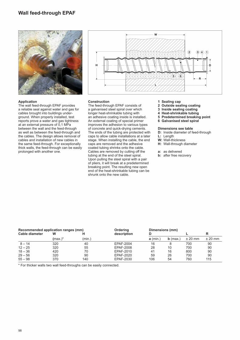
98
Wall feed-through EPAF
ApplicationThe wall feed-through EPAF provides a reliable seal against water and gas forcables brought into buildings under -ground. When properly installed, testreports prove a water and gas tightnessat an external pressure of 0,1 MPabetween the wall and the feed-throughas well as between the feed-through andthe cables. The design allows removal ofcables and installation of new cables inthe same feed-through. For exceptionallythick walls, the feed-through can be easilyprolonged with another one.
ConstructionThe feed-through EPAF consists of a galvanised steel spiral over whichlonger heat-shrinkable tubing with an adhesive coating inside is installed.An external coating of special primerimproves the adhesion to various typesof concrete and quick-drying cements.The ends of the tubing are protected withcaps to allow cable installations at a laterstage. When installing the cable, the endcaps are removed and the adhesivecoated tubing shrinks onto the cable.Cables are removed by cutting off thetubing at the end of the steel spiral.Upon pulling the steel spiral with a pairof pliers, it will break at a predeterminedbreaking point. The resulting new openend of the heat-shrinkable tubing can beshrunk onto the new cable.
1 Sealing cap2 Outside sealing coating3 Inside sealing coating4 Heat-shrinkable tubing5 Predetermined breaking point 6 Galvanised steel spiral
Dimensions see tableD: Inside diameter of feed-throughL: Length W: Wall-thicknessH: Wall-through diameter
a: as deliveredb: after free recovery
Recommended application ranges (mm) Ordering Dimensions (mm)Cable diameter W H description D L R
(max.)* (min.) a (min.) b (max.) ± 20 mm ± 20 mm
8 – 14 320 40 EPAF-2004 16 8 700 9012 – 25 320 55 EPAF-2008 28 10 700 9018 – 36 420 70 EPAF-2010 41 16 800 9029 – 56 320 90 EPAF-2020 59 26 700 9055 – 98 370 140 EPAF-2030 106 54 760 115
* For thicker walls two wall feed-throughs can be easily connected.
R
L
W
DH
2 3 4 1
5 6

99
Unsealed cable pipes and ducts need nolonger cause dampness and flooding insubstation basements, cable vaults andaccess manholes. In these environmentsrust, corrosion and a humid environmentinevitably result in damage to supportstructures, metal work and electricalequipment. The most common route forwater to enter into such installations cannow be blocked simply and effectively bya new technique developed by Raychem.The Rayflate Duct Sealing System(RDSS) has been designed for use onpower cables to provide a watertight sealwhen used with plastic, concrete or steelducting systems.
Clean, fast, easy sealing methodThe Rayflate seal consists of an inflatablebladder of flexible, metallic laminate,coated on both sides with a sealant strip.With the sealant strips lubricated, theproduct is simply wrapped around thecable and easily slides into the duct.The bladder is then inflated with a gaspressure tool which presses the sealantcoating against the duct wall and thecable. Upon removal of the filling tube,an automatic gel valve system reliablyretains the gas pressure in the Rayflateduct seal.The entire installation is performed withina few minutes – even in congestedenclosures.
Versatility and easy removalThe RDSS system adapts itself to anyconfiguration and is independent of ductovality. Each RDSS seal covers a largerange of cable and duct diameters.The versatility of the wraparound conceptenables use not only for new cable instal -lations, but also for existing applica tions.Unlike other methods that require dryducts, the Rayflate seals can be installedwhen water is still flowing out of the duct.The duct seals can be quickly and easilyremoved from a duct or pipe by deflation.This allows cables to be replaced in anupgrade or repair. Since ducts are notdamaged by the RDSS system, they caneasily be sealed again.
100 mm
Performance testedTests at room temperature showed waterand air tightness at static pressures ofmore than 0,3 bar, even in conjunctionwith cable bending, vibration, torsion andaxial pull.Resistance to common chemicals hasbeen proven by immersion tests. TheRayflate system was tested with cablesload-cycled at conductor temperaturesof 90 °C, similar to specifications requiredfor cable accessories. The sealing testsshowed water and air tightness withinternal duct pressures of 0,3 bar.Measurements and calculations of thediffusion rate indicate that a typicalRayflate duct seal will withstand a 3 mwaterhead for 30 years after installation.The sealing performance after 30 yearsof life was confirmed by sealing tests withreduced internal bladder pressures.The test methodologies and parametersare set out in a detailed test reportavailable from your local TE Energyproducts representative.
Duct sealing system RDSS

100
Duct Product descriptioninside Ø RDSS-45 RDSS-60 RDSS-75 RDSS-100 RDSS-125 RDSS-150
cable Ø cable Ø cable Ø cable Ø cable Ø cable Ø
32,5 0–14
35 0–18
40 0–27
45 0–32 0–18
50 0–30
55 0–38 0–28
60 0–45 0–30
65 0–40
70 0–46
75 0–56 0– 45
80 0– 52
85 0– 60
90 0– 66
95 0– 74
100 0– 80 0– 65
105 0– 85 0– 75
110 0– 90 0– 83
115 55– 95* 0– 91
120 60–100* 0– 95
125 0–103 60–100
130 70–110* 60–107
135 75–115* 60–112
140 80–120* 60–118
145 85–125* 60–123
150 90–130* 60–129
155 60–134*
160 60–139*
165 105–145*
170 110–150*
175 115–155*
180 120–160*
clip RDSS- RDSS- RDSS- RDSS- RDSS- RDSS-selection Clip-45 Clip-75 Clip-75 Clip-100 Clip-125 Clip-150
If three or more cables have to be sealed,a RDSS-Clip is used in combination withthe RDSS duct seal. The sealing clip hasto be ordered separately. For each clip used, subtract 5 mm fromthe maximum cable diameter shown inthe table to determine the maximum cablebundle diameter. One RDSS-clip seals up to 4 cables.If more cables are to be sealed, use oneextra clip as shown above.
Suitable for empty ductsWith cables only
* RDSS-clips must also be used for 2 or more cable configurations.
Each RDSS seals empty ducts (except for size 150) and ducts containing up to2 cables. The table below shows the minimum and maximum diameter of the cable or of the sum of 2 cables depending on the duct size. All dimensions in mm.
Diameter of cable or cable bundles
D D
Tools for easy and quick inflationRayflate duct seals can be installed usinga wide variety of inflation tools, whichhave the capability to inflate the bag to3,0 ±0,2 bar pressure. For recommended installation tools seethe chapter “Tools and Accessories”:- inflation tool RDSS-IT-16,- gas cylinders E7512-0160.
RDSS – Selection table for duct seals and sealing clips

101
For sealing of cable bundles select the appropriate RDSS-clip according to the selectiontable on the previous page
Suitable for empty ductsWith cables only
* Empty ducts only
The RDSS-AD-210 adapter is designed to be installed together with RDSS-125 andRDSS-150 duct seals for ducts up to 210 mm in diameter.
After the sealant tape has been lubricated the RDSS-AD-210 adapter is coiled aroundthe cable to fit the duct. The coiled adapter slides easily into the duct and when releasedsnaps into position against the inner wall of the duct. Then the RDSS is insertedbetween the cable and the pre-positioned adapter and inflated in the usual way. Certainconfigurations may require two adapters, details are given in the selection table.The RDSS adapter performance was tested together with RDSS duct seals includingwatertightness even when the cables were subjected to loadcycling, vibration orbending. A detailed test report is available on request.
The table below shows the minimum and maximum diameter of the cable or cablebundle that can be accommodated in a cable duct for a specific combination of RDSSseals and RDSS-AD-210 adapter. All dimensions in mm.
RDSS – Adapter for large duct sizes
Duct Product combination inside Ø 1xRDSS-AD-210 2xRDSS-AD-210 1xRDSS-AD-210 2xRDSS-AD-210
+ RDSS-125 + RDSS-125 + RDSS-150 + RDSS-150cable Ø cable Ø cable Ø cable Ø
130 0*
135 0*
140 0– 40
145 0– 50
150 0– 65
155 0– 83
160 0– 91
165 0–103
170 70–110 0* 60–107
175 75–115 0– 40 60–112
180 80–120 0– 50 60–118
185 90–130 0– 65 60–129
190 0– 83 60–135
195 0– 95 60–139
200 0–103 105–145 60–100
205 75–115 115–155 60–112
210 80–120 120–160 60–118

102
Sealing Breakouts for 2 to 5 core cables and ducts
ApplicationFor sealing of LV multi-core cablescrutches and cable entries into ducts. To seal onto all common plastics andmetals, all outlets are coated withhot-melt adhesive. The breakouts areresistant to UV-light and weathering.
The breakouts are available for 2-, 3-, 4-and 5-core cables, in a variety of sizes.For dimensional details see table below.
a: as deliveredb: after free recovery
Dimensions see tableH: Diameter of large outletJ: Diameter of small outletsK: Diameter of the smallest outletP: Length of breakoutR: Length of large outletS: Length of small outletsHW: Wall-thickness of large outletJW: Wall-thickness of small outletsKW: Wall thickness of the smallest outlet
Recommended Ordering Dimensions (mm)cross section description H J K P R S HW JW/KWof polymeric cables a b a b a b b b b b b(mm2) min. max. min. max. min. max. ±10% ±10% ±10% ±20% ±20%
for 2-core cables4 – 25 302K333/S 28 9,2 15 4,1 - - 90 20 25 3,2 1,6
35 – 150 302K224/S 48 32 22 7 - - 172 - 70 2,0 2,0150 – 400 302K466/S 86 42 40 17 - - 200 - 75 2,5 2,5
for 3-core cables4 – 35 402W533/S 38 13 16 4,2 - - 103 45 28 2,7 1,5
50 – 150 402W516/S 63 22 26 9 - - 180 85 40 3,5 1,595 – 500 402W526/S 95 28 44 13 - - 205 90 45 3,5 2,5
– 402W248/S 115 45 52 22 - - 240 100 60 4,0 2,5– 402W439/S 170 60 60 30 - - 252 90 66 4,2 2,6
for 4-core cables1,5 – 10 502S013/S 23 9,5 7 2 - - 60 - 17 2,0 1,2
4 – 35 502K033/S 45 16,5 14 3,4 - - 97 73 25 2,5 1,925 – 95 502K046/S 45 19 20 7 - - 165 75 40 3,5 2,050 – 150 502K016/S 75 25 25 9 - - 217 100 44 3,5 2,0
120 – 400 502K026/S 100 31 40 13,5 - - 223 103 51 3,5 2,5– 502R810/S 170 60 50 23 43 19 255 90 65 4,0 3,5
for 4+1 core cables25 – 120* 603W035/S 68 26 30 7 20 6 182 75 40 3,2 2,225 – 240 603W040/S 85 26 33 7 27 6 182 75 40 3,2 2,2
* For smaller cross sections use 502K033/S with 2 cores inside of one outlet.
JW S RHW
H
J
adhesive
P
KW
K
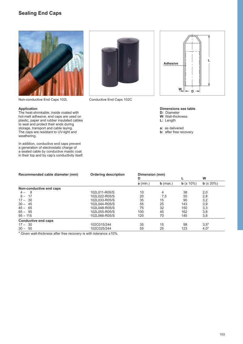
103
Sealing End Caps
ApplicationThe heat-shrinkable, inside coated withhot-melt adhesive, end caps are used onplastic, paper and rubber insulated cablesto seal and protect their ends duringstorage, transport and cable laying.The caps are resistant to UV-light andweathering.
In addition, conductive end caps preventa generation of electrostatic charge of a sealed cable by conductive mastic coatin their top and by cap’s conductivity itself.
Dimensions see tableD: DiameterW: Wall-thicknessL: Length
a: as deliveredb: after free recovery
Recommended cable diameter (mm) Ordering description Dimension (mm)D L W
a (min.) b (max.) b (± 10%) b (± 20%)
Non-conductive end caps4 – 8 102L011-R05/S 10 4 38 2,08 – 17 102L022-R05/S 20 7,5 55 2,8
17 – 30 102L033-R05/S 35 15 90 3,230 – 45 102L044-R05/S 55 25 143 3,945 – 65 102L048-R05/S 75 32 150 3,365 – 95 102L055-R05/S 100 45 162 3,895 – 115 102L066-R05/S 120 70 145 3,8
Conductive end caps17 – 30 102C015/244 35 15 98 3,5*30 – 50 102C025/244 55 25 123 4,0*
* Given wall-thickness after free recovery is with tolerance ±10%.
L
DW
Non-conductive End Caps 102L Conductive End Caps 102C
Adhesive

104
Insu
latio
n T
ubin
g an
d R
epai
r Ta
pe a
nd W
rapa
roun
ds

105
Heat-shrinkable insulation tubing
General purpose
Thin-wall, adhesive coated tubing EN-CGAT 106
Halogen-free
Thick-wall, general purpose tubing WCSM 106
Medium-wall, general purpose tubing MWTM 107
Flame retardant
Thick-wall, flexible tubing FCSM 108
Medium-wall, flexible tubing LVIT 108
Thin-wall, flexible tubing EN-CGPT 109
Thin-wall, dual-colour (green-yellow) tubing EN-DCPT 109
Halogen-free and flame retardant
Thick-wall, general purpose tubing ZCSM 110
Repair tape and wraparounds
Flame retardant, flexible tape CRPS 111
General purpose, fibre-reinforced wraparound CNSM 112
Thick-wall, fibre-reinforced wraparound RFSM 113

106
Recommended application Ordering description Dimension (mm)diameter (mm) D Wmin. max. a (min.) b (max.) b (min.)
1,1 2,0 EN-CGAT- 3/ 1-0-SP 3 1 1,002,2 4,0 EN-CGAT- 6/ 2-0-SP 6 2 1,003,3 7,0 EN-CGAT- 9/ 3-0-SP 9 3 1,354,5 9,0 EN-CGAT-12/ 4-0-SP 12 4 1,507,0 16,0 EN-CGAT-18/ 6-0-SP 18 6 1,709,0 21,0 EN-CGAT-24/ 8-0-SP 24 8 1,95
14,5 36,0 EN-CGAT-39/13-0-SP 39 13 2,10
General purpose heat-shrinkable polyolefin insulation tubing
EN-CGATThin-wall, heat-shrinkable tubing
ApplicationGeneral electrical insulation, sealing andcorrosion protection purposes. The tubing is coated with an inner sealantwall and it is weathering and UV-resistant.
FeaturesShrink-ratio: 3:1Temperature range: - 40 °C to +80 °CColour: blackDelivery form: on spools, adhesive coated
Recommended application Ordering description Dimension (mm)diameter (mm) D Wmin. max. a (min.) b (max.) a (min.) b (min.)
3,5 10 WCSM- 12/ 3-1000/S 12 3 0,8 2,04,5 14 WCSM- 16/ 4-1000/S 16 4 0,9 2,46,5 22 WCSM- 24/ 6-1000/S 24 6 1,0 2,79 31 WCSM- 34/ 8-1000/S 33 8 1,3 4,0
13 44 WCSM- 48/ 12-1000/S 48 12 1,5 4,517,5 50 WCSM- 56/ 16-1000/S 56 16 1,5 4,422 63 WCSM- 70/ 20-1000/S 70 20 1,4 4,427 81 WCSM- 90/ 25-1000/S 90 25 1,3 4,333 100 WCSM-110/ 30-1000/S 110 30 1,2 4,338 118 WCSM-130/ 35-1000/S 130 35 1,2 4,355 144 WCSM-160/ 50-1000/S 160 50 1,0 4,355 162 WCSM-180/ 50-1000/S 180 50 1,0 4,355 180 WCSM-200/ 50-1000/S 200 50 n.a. 4,370 225 WCSM-250/ 65-1000/S 250 65 n.a. 4,3
105 295 WCSM-320/ 95-1000/S 320 95 n.a. 4,3125 350 WCSM-390/110-1000/S 390 110 n.a. 4,3
Note: Maximal longitudinal change after free recovery (+5 %; -10 %)
WCSMThick-wall, halogen-free heat-shrinkable tubing
ApplicationGeneral electrical insulation and sealingpurposes. The tubing is coated with aninner sealant wall. The sealant exhibitsexcellent bonding and sealingcharacteristics to all materials commonlyused in the various cable insulation andsheath constructions, such as plastic,rubber, lead and aluminium.The tubing is weathering and UV-resistant.
FeaturesTemperature range: - 50 °C to +90 °CDielectric strength: 170 kV/cm (1 mm wall)
120 kV/cm (2 mm wall) Colour: blackDelivery form: 1 m cut lengths, adhesive coated
Halogen-free, heat-shrinkable polyolefin insulation tubing

107
Halogen-free, heat-shrinkable polyolefin insulation tubing
MWTMMedium-wall, halogen-free heat-shrinkable tubing
ApplicationGeneral electrical insulation, sealing andcorrosion protection purposes. The tubingis available either with or without an inner sealant wall. The sealant exhibitsexcellent bonding and sealing charac -teristics to all materials commonly used inthe various cable insulation and sheathconstructions, such as plastic, rubber,lead and aluminium.The tubing is weathering and UV-resistant.
Recommended application Ordering description Dimension (mm)diameter (mm) uncoated tubing* adhesive coated tubing D Wmin. max. a (min.) b (max.) a (min.) b (min.)
3,5 9 MWTM- 10/ 3-1000/U MWTM- 10/ 3-1000/S 10 3 0,3 1,05,5 14,5 MWTM- 16/ 5-1000/U MWTM- 16/ 5-1000/S 16 5 0,3 1,49 22,5 MWTM- 25/ 8-1000/U MWTM- 25/ 8-1000/S 25 8 0,4 2,0
13 31,5 MWTM- 35/ 12-1000/U MWTM- 35/12-1000/S 35 12 0,4 2,018 45 MWTM- 50/ 16-1000/U MWTM- 50/16-1000/S 50 16 0,5 2,021 57 MWTM- 63/ 19-1000/U MWTM- 63/19-1000/S 63 19 0,6 2,424 68 MWTM- 75/ 22-1000/U MWTM- 75/22-1000/S 75 22 0,6 2,728 77 MWTM- 85/ 25-1000/U MWTM- 85/25-1000/S 85 25 0,6 2,832 86 MWTM- 95/ 29-1000/U MWTM- 95/29-1000/S 95 29 0,7 3,137 104 MWTM-115/ 34-1000/U MWTM-115/34-1000/S 115 34 0,7 3,146 126 MWTM-140/ 42-1000/U MWTM-140/42-1000/S 140 42 0,7 3,155 144 MWTM-160/ 50-1000/U MWTM-160/50-1000/S 160 50 0,7 3,266 162 MWTM-180/ 60-1000/U MWTM-180/60-1000/S 180 60 0,7 3,288 220 MWTM-245/ 80-1000/U - 245 80 n.a. 2,4
149 255 MWTM-285/135-1000/U - 285 135 n.a. 1,4
* Uncoated tubing is also available on spool (please use modification code –A/U instead of -1000/U in relevant ordering description).Note: Maximal longitudinal change after free recovery (+5 %; -10 %).
FeaturesTemperature range: - 40 °C to +120 °C (uncoated)
- 40 °C to + 90 °C (coated)Dielectric strength: 200 kV/cm (1 mm wall)Colour: blackDelivery form: 1 m cut lengths, uncoated = 1000/U
1 m cut lengths, adhesive coated = 1000/Son spools, uncoated only = A/U
Dimensions:D: DiameterDa: Diameter as deliveredDb: Diameter after free recoveryW: Wall-thickness Wa: Wall-thickness as deliveredWb: Wall-thickness after free recovery
Wb
Da Db
WaWa
Wb
DbDa
adhesive

108
Flame retardant, heat-shrinkable polyolefin insulation tubing
FCSMThick-wall, flexible and flame-retardedheat-shrinkable tubing
ApplicationElectrical insulation and sealing purposesin the mining, construction and transporta-tion industries and for similar applications,where flame retardation and flexibility arerequired.The tubing is coated with an inner sealantwall and it is weathering and UV-resistant.
FeaturesTemperature range: - 50 °C to +90 °CDielectric strength: 130 kV/cmFlammability (IEC 60684-2 method A): self-extinguishing 60 sec. max.Colour: blackDelivery form: 1 m cut lengths, adhesive coated
Recommended application Ordering description Dimension (mm)diameter (mm) D Wmin. max. a (min.) b (max.) a (min.) b (min.)
3,5 8 FCSM- 9/ 3-1000/S 9 3 0,6 2,06,5 17 FCSM- 19/ 6-1000/S 19 6 0,7 2,4
10 25 FCSM- 28/ 9-1000/S 28 9 0,8 3,213 34 FCSM- 38/12-1000/S 38 12 1,0 4,117,5 46 FCSM- 51/16-1000/S 51 16 1,0 4,124 61 FCSM- 68/22-1000/S 68 22 1,0 4,133 81 FCSM- 90/30-1000/S 90 30 1,0 4,144 108 FCSM-120/40-1000/S 120 40 1,0 4,169 159 FCSM-177/63-1000/S 177 63 1,0 4,1
Note: Maximal longitudinal change after free recovery (+5 %; -10 %)
LVITMedium-wall, flexible and flame-retarded heat-shrinkable tubing
ApplicationElectrical insulation, protection andsealing of flexible cables, joints,accessories, connections and variety ofcurved and bent busbars of both circularand rectangular cross-section.The tubing is weathering and UV-resistant.
FeaturesTemperature range: - 50 °C to +105 °CDielectric strength: 130 kV/cm (2,5 mm wall) Flammability (IEC 60684-2 method A): self-extinguishing 60 sec. max.Colour: blackDelivery form: on spools, uncoated only = A/U
Recommended application (mm) Ordering description Dimensions (mm)Rectangular Roundbusbars, L+T busbars, B D Wmin. max. min. max. a (min.) b (max.) a (min.) b (min.)
17 39 11 25 LVIT- 30/ 10-A/U 30 10 0,5 1,5 39 86 25 55 LVIT- 75/ 25-A/U 75 25 0,5 1,565 140 40 90 LVIT- 100/ 35-A/U 100 35 0,5 1,586 157 55 100 LVIT- 150/ 50-A/U 150 50 0,5 1,5
190 280 120 180 LVIT- 235/105-A/U 235 105 0,5 1,5
L
T or T
r = min. 0,8 mm
B

109
Flame retardant, heat-shrinkable polyolefin insulation tubing
Recommended application Ordering description Dimension (mm)diameter (mm) D Wmin. max. a (min.) b (max.) b (min.)
0,6 1,3 EN-CGPT- 1,5/0,5-0-SP 1,5 0,5 0,451,1 2,5 EN-CGPT- 3/ 1-0-SP 3 1 0,552,2 5,0 EN-CGPT- 6/ 2-0-SP 6 2 0,653,3 8,0 EN-CGPT- 9/ 3-0-SP 9 3 0,754,5 10,5 EN-CGPT-12/ 4-0-SP 12 4 0,757,0 16,0 EN-CGPT-18/ 6-0-SP 18 6 0,859,0 21,5 EN-CGPT-24/ 8-0-SP 24 8 1,00
14,5 35,0 EN-CGPT-39/13-0-SP 39 13 1,15
Note: Tubing in other colours is available on request.
Recommended application Ordering description Dimension (mm)diameter (mm) D Wmin. max. a (min.) b (max.) b (min.)
1,7 2,8 EN-DCPT- 3/ 1,5-45-SP 3 1,5 0,513,2 5,6 EN-DCPT- 6/ 3-45-SP 6 3 0,584,5 7,6 EN-DCPT- 8/ 4-45-SP 8 4 0,645,5 9,5 EN-DCPT-10/ 5-45-SP 10 5 0,646,5 11,5 EN-DCPT-12/ 6-45-SP 12 6 0,64
10,0 18,0 EN-DCPT-19/ 9-45-SP 19 9 0,7614,0 25,0 EN-DCPT-26/13-45-SP 26 13 0,8923,0 35,0 EN-DCPT-38/19-45-SP 38 19 1,00
EN-CGPTThin-wall, flexible and flame-retardedheat-shrinkable tubing
ApplicationUniversal electrical insulation, corrosionprotection and marking purposes.The tubing is weathering and UV-resistant.
FeaturesShrink-ratio: 3:1Temperature range: - 40 °C to +135 °CFlammability (IEC 60684-2 method A): self-extinguishing 60 sec. max.Colour: blackDelivery form: on spools, uncoated
EN-DCPTThin-wall, flame-retarded heat-shrinkable tubing
ApplicationMarking and protection of groundingwires, cables and busbars.The tubing is weathering and UV-resistant.
FeaturesShrink-ratio: 2:1Temperature range: - 40 °C to +135 °CFlammability (IEC 60684-2 method A): self-extinguishing 60 sec. max.Colour: green/yellowDelivery form: on spools, uncoated
Dimensions:D: DiameterDa: Diameter as deliveredDb: Diameter after free recoveryW: Wall-thickness Wa: Wall-thickness as deliveredWb: Wall-thickness after free recovery
Wa
Wb
DbDa

110
Recommended application Ordering description Dimension (mm)diameter (mm) D Wmin. max. a (min.) b (max.) a (min.) b (min.)
3,5 7 ZCSM- 8/ 3-1000/U 8 3 0,6 2,05,5 14,5 ZCSM- 16/ 5-1000/U 16 5 0,7 2,49 21,5 ZCSM- 24/ 8-1000/U 24 8 0,9 2,9
13 29 ZCSM- 32/12-1000/U 32 12 1,0 4,017,5 40,5 ZCSM- 45/16-1000/U 45 16 1,0 4,024 54 ZCSM- 60/22-1000/U 60 22 1,0 4,027,5 63 ZCSM- 70/25-1000/U 70 25 1,0 4,039,5 76,5 ZCSM- 85/36-1000/U 85 36 1,0 4,055 108 ZCSM-120/50-1000/U 120 50 1,0 4,282,5 162 ZCSM-180/75-1000/U 180 75 1,0 5,6
Halogen-free and flame retardant, heat-shrinkable polyolefin insulation tubing
ZCSMThick-wall, halogen-free and flame-retarded heat-shrinkable tubing
ApplicationGeneral electrical insulation purposesespecially in low fire hazard areas.The tubing is weathering and UV-resistant.
FeaturesTemperature range: - 40 °C to +140 °CFlame propagation (IEC 60332-1): passLimited oxygen index (ISO 4589): 29 min.Temperature index (ISO 4589): 250 °C min.Smoke index (NES 711): 20 max.Smoke density (3 m3) (IEC 61034): passToxicity Index (NES 713): 3 per 100 g max.Acid gas generation (IEC 60754): 1,5 % max.Dielectric strength: 120 kV/cm (2 mm wall)Colour: blackDelivery form: 1 m cut lengths, uncoated
Dimensions:D: DiameterDa: Diameter as deliveredDb: Diameter after free recoveryW: Wall-thickness Wa: Wall-thickness as deliveredWb: Wall-thickness after free recovery
Wa
Wb
DbDa

111
Flame retardant, elastomeric repair tape
CRPSFlexible, flame-retardant cold appliedrepair tape
ApplicationJacket repair on mining and other flexiblecables. The tape has excellent resistanceto abrasion, tearing, and cutting and it isprecoated with a thermoplastic sealantthat provides a superb seal againstmoisture and corrosive elements.
Cable Ordering Tape Tape Max. coverage diameter description length width length(mm) (mm) (mm) (mm)
13 185519 124525 91532 71038 CRPS-2120 3050 50 61044 51051 48064 33076 305
Note: Max. coverage length includes 150 mm on either side of damaged area.For larger damaged areas, multiple strips may be used to provide continuouscoverage.
damaged area
coverage length
150 mm 150 mm

112
Fibre-reinforced, heat-shrinkable repair wraparound
CNSMGeneral purpose, fibre-reinforced, heat shrinkable wraparound
ApplicationFast and reliable repair of polymeric orpaper cable sheaths to re-establish theelectrical and mechanical integrity of thecable.The wraparound is supplied with anadhesive coating and it is weathering and UV-resistant.
FeaturesTemperature range: - 40 °C to +120 °CDielectric strength: 120 kV/cm (1 mm wall).Colour: blackDelivery form: adhesive coated wraparound with stainless steel channel Temperature indicating system: Outer surface of wraparound is treated with a temperature sensitive indicating system
to facilitate uniform heating during installation. In addition, white lines are painted on theflat side of the rails, which become visible through the channel openings as installationis completed.
Recommended Ordering description Dimensions (mm) application D W Ldiameter (mm)min. max. a (nom.) b (max.) a (min.) b (min.) a (±5 mm)
8 43 CNSM- 43/ 8-1000/AC 53 8 1,1 3 100012 55 CNSM- 55/12-1000/AC 66 12 1,1 3 100015 75 CNSM- 75/15-1000/AC 84 15 1,1 3 100020 84 CNSM- 84/20-1000/AC 92 20 1,1 3 100025 100 CNSM-100/25-1000/AC 115 25 1,1 3 100030 125 CNSM-125/30-1000/AC 136 30 1,1 3 100038 146 CNSM-146/38-1000/AC 162 38 1,1 3 100042 164 CNSM-164/42-1000/AC 176 42 1,1 3 100050 200 CNSM-200/50-1000/AC 216 50 1,1 3 1000
Note: Maximal longitudinal change after free recovery ±5 %.The repair wraparound and the channel can be cut to the length as required at the place of installation.Other lengths are available on request.
D
W
L
Dimensions:D: DiameterDa: Diameter as deliveredDb: Diameter after free recoveryL: LengthW: Wall-thickness Wa: Wall-thickness as deliveredWb: Wall-thickness after free recovery
adhesive

113
Recommended Ordering description Dimensions (mm) application D W Ldiameter (mm)min. max. a (min.) b (max.) a (min.) b (min.) a (±15 mm)
16 41RFSM- 45/15- 500/123
50 13 1,5 4,5500
RFSM- 45/15- 750/123 750
22 59RFSM- 65/20- 500/123
71 18 1,5 4,5500
RFSM- 65/20-1000/123 1000
RFSM- 95/30- 750/123 75033 86 RFSM- 95/30-1000/123 103 27 1,5 4,5 1000
RFSM- 95/30-1500/123 1500
RFSM-125/40- 750/123 75044 113 RFSM-125/40-1100/123 135 36 1,5 4,5 1100
RFSM-125/40-1500/123 1500
61 149RFSM-165/55- 750/123
178 50 1,5 4,5750
RFSM-165/55-1500/123 1500
71 185RFSM-205/65- 750/123
222 59 1,5 4,5750
RFSM-205/65-1500/123 1500
Note: Maximal longitudinal change after free recovery ±10 %.
RFSMThick-wall, fibre-reinforced, heat shrinkable wraparound
ApplicationFast and reliable cable repairs inapplications where high mechanicalresistance is required and as an outersheath for low and medium voltage joints.The wraparound is supplied with anadhesive coating and it is weathering andUV-resistant.
FeaturesTemperature range: - 40 °C to +120 °CDielectric strength: 120 kV/cm (1 mm wall)Colour: blackDelivery form: adhesive coated wraparound with stainless steel channel Temperature indicating system: Outer surface of wraparound is treated with a temperature sensitive indicating system
to facilitate uniform heating during installation. In addition, white lines are painted on theflat side of the rails, which become visible through the channel openings as installationis completed.
Fiber-reinforced, heat-shrinkable repair wraparound
D
W
L
Dimensions:D: DiameterDa: Diameter as deliveredDb: Diameter after free recoveryL: LengthW: Wall-thickness Wa: Wall-thickness as deliveredWb: Wall-thickness after free recovery
adhesive

114
Hig
h V
olta
ge C
able
Acc
esso
ries

115
High Voltage Cable Accessories
General 116
Outdoor Composite Terminationfor 72 kV up to 245 kV 118
Dry Self-Supporting Outdoor Terminationfor 145 kV 120
Dry Compact Switchgear and TransformerTermination for 72 kV up to 245 kV 122
One-piece Joint up to 245 kV 124
Tree-piece Joint up to 170 kV 126

116
General
TE Energy is focused on development, manufacturing of cable accessories and execution of projects providing reliable operation of electric power systems. Manyof the world’s leading enterprises apply our cable accessories which are developed for the long-term operation in the most severe conditions of indoor and outdoormaintenance in any climatic zones and high pollution locations. Our products have a very high reliability index which warrants saving of customers capital outlays. We use experience accumulated from more than 40 years in materials science,development of new technologies, and intensive study of customers needs. Weconstantly improve our production technology and the quality of our products whilepaying attention to customers increasing requirements. Our products passed all relevant tests in independent test labs in order to comply with quality requests of International Standards like IEC, IEEE. TE Energy has technical support centerswhere customers can get professional assistance. Our specialists are always ready to find solutions for any specific issue of any enterprise.
Technology
Pre-Moulded main insulationPush-on stress cone made of silicone rubber offers:- wide application range- easy installation, no pulling device required- no holdout system required
Solderless connection technologyTop bolts and connectors with shear-head bolts offer:- no crimping tools required- reproducible high electrical contact quality by preset shear-off torque- suitable for all conductor material and design
Roll-spring or hose clips connection of cable sheath / screen offers:- no risk of cable damage- fast installation- easy adaptation to cable with two or more shield layers
Heat-shrink outer sealing systemMolecular crosslinked polymer with hot-melt and mastic coating offers:- reliable sealing against moisture ingress- mechanical protection of the joint body- easy and well know installation
Basic project information
Minimum preliminary technical data and information must be collected to prepare a quotation.
For all applications:- system voltage- drawing of cable- all cable parameters like conductor and screen material, conductor and screen cross
section, conductor diameter etc.
In addition for:Outdoor Composite and Dry Terminations- accessories material, bus-bar or conductor
Switchgear and Transformer Terminations- connection details, standard and type
Inline and Shield-break joints- length of cable line

117
Strategy, service and installation
TE Energy is an independent supplier of HV cable accessories offering its productsworldwide to:
- utilities with their own installation crews- contractors providing installation services to utilities and industrial customers- cable manufacturers
An engineering team provides support during the planning phase of a project.Field experienced TE Energy employees and representatives support customers fromthe planning to the finalization of projects.
InstallationsTE Energy has well-trained and experienced jointers who are able to carry outinstallation at construction sites. Usually they are supported by local assistanceprovided by the contractor or the local utility. If there are no trained jointers availablelocally, ordering installation services from us is the first choice.
TrainingJointers with longtime experience in HV cable preparation may be trained on-site duringan installation. Less experience jointers should be first trained in our labs. In both cases,well experienced supervisors demonstrate how to install our products to ensure the highperformance expected is maintained over the whole life time of our products. At the endof the training the jointers will be able to carry out installations without or at least with a minimum of help provided by our supervisors.
SupervisionJointers, who have been trained by TE Energy supervisors prior to an installation buthaven’t yet had sufficient on-site experience in installing of TE Energy accessories, mayneed the help of a supervisor on-site. We recommend ordering this service for the firstinstallations. This ensures that all accessories are installed according to the instructionsprovided with the accessories.
TE Energy high voltage products
Wide range of reliable and cost-effective solutions is continuously expanding throughthe field knowledge, customer’s feedback and research-driven product development.
TE Energy transmission line and substation competence
- cable terminations and joints- link boxes- insulation enhancement system- surge arresters and surge counters- connectors up to 800 kV- hollow core polymeric and porcelain insulators- spacer and dampers- hardware and fittings- suspension clamps- mechanical dead ends- earthing and grounding systems- fibre reinforced components

118
ApplicationThe termination is designed for voltageclasses up to 245 kV and to operate under severe environmental conditions.Polymeric insulated cables of variousdesigns can be adopted with respect to shielding and metal sheath.Composite housings with differentcreepage lengths up to 50 mm/kV areavailable covering the most common and also extreme pollution levels.
Features• Designed in accordance to IEC-60071-1,
IEC-60071-2 and IEEE-1313.1• Pressure-tight and light weight
composite housing• Pre-fabricated and factory tested
silicone rubber stress cone• Torque-controlled conductor bolt• Heat-shrink components used for
sealing• No special tools required to install the
termination• Si-oil filling without preheating (filling
from the top)• Isolated base plate for sectionalization• Fittings made of corrosion resistant alloy• Type tested according to IEC-60840 and
IEEE-48 standards
Outdoor Composite Termination OHVT-C for 72 kV up to 245 kV
2
1
Model variations System Add ons
CreepageVariations according to individualrequirements• pollution class• normal sheds• alternating sheds
AdapterVariations to customize thetermination contact bolt
Cable lugDifferent types of cable lugs available• mechanical with defined torque• crimp octant or hexagonal
Arcing hornTo adjust the arcing distance
3
4
5
6
7
8
9
Cut-away drawing of OHVT-C1 Connector (mechanical or crimp)2 Sealing system3 Upper metal fitting4 Composite housing5 Oil-filling6 Stress cone7 Base plate8 Support insulators9 Gland and sealing

119
Outdoor Composite Termination OHVT-C for 72 kV up to 245 kV
F
E
G
B
4x M12
B
D
A
C
Type of termination OHVT-72C OHVT-145C OHVT-170C OHVT-245C
Technical dataMax. operating voltage Um (kV) 72,5 145 170 245Standards IEC-60840 IEC-60840 IEC-60840 IEC-62067
IEC-60815 IEC-60815 IEC-60815 IEC-60815Rated voltage U (kV) 60 – 69 132 – 138 150 – 161 220 – 230Rated lightning impulse 1,2/50 µswithstand voltage (BIL) (kV)
325 650 750 1050
Min. creepage distance (mm) 2164 – 2383 3392 – 8047 3829 – 9436 5161 – 10171Partial discharge measurement (pC) < 5 < 5 < 5 < 5Max. continuous operating temperature (°C) 90 90 90 90Max. conductor emergency temperature (°C) 150 150 150 150Conductor short circuit temperature (°C) 250 250 250 250Short circuit current (sheath) (kA/s) 40 40 40 40Withstand voltage supportinsulators (AC/DC) (kV)
10/20 10/20 10/20 10/20
Application RangeConductor cross section Cu/Al (mm2) 95 – 2500 95 – 2500 95 – 2500 300 – 2500Diameter over cable insulation (mm) 34 – 97 34 – 97 43 – 108 77 – 119Max. diameter over cable sheath (mm) 110 110 135 170
DimensionsA (mm) 345 345 345 345B M16 M16 M16 M16C (mm) 350 350 350 350D (mm) 1072 – 1276 1771 – 2608 2028 – 2854 2523 – 3227E (mm) 100/130 100/130 100/130 110/130F (mm) 30/40/50 30/40/50 30/40/50 50/60G (mm) 294/304 294/304 345/355 402/410
Note: All listed dimensions are standard size to serve the common application of these terminations.Special applications, bigger cable sizes and more detailed information are available on request.

120
ApplicationThe dry self-supporting termination isdesigned for voltage class 145 kV andoperation under severe environmentalconditions. It is free from any insulatingliquid or gel. Polymeric insulated cables of various designs can be adopted withrespect to shielding and metal sheath. The termination is easily separable andconsists of a plug-in part and an epoxyresin insulator protected with a directlymoulded silicone shed housing. Due to the short cable cut-back dimensions of the plug-in the time required to install thetermination is very short and can befurther reduced by pre-installing the plug-in on the shop floor. The plug-in is similar to the plug-in used with our dry switchgear/transformer termination.
Features• Dry interface, no oil-filling• Self-supporting• Pre-fabricated and factory tested
silicone rubber stress cone• Torque-controlled multi-contact
conductor bolt• Fast and simple installation combining
gas-insulated switchgear plug-intechnology with polymeric insulators
• No special tools required to install thetermination
• Isolated cable gland for sectionalization• Type tested according to IEC-60840
Dry Self-Supporting Outdoor Termination OHVT-D for 145 kV
2
1
3
4
5
6
7
8
Cut-away drawing of OHVT-D1 Upper metal fitting2 Mechanical connector3 Resin body with silicone shed housing4 Stress cone5 Spring-loaded compression ring6 Base plate7 Support insulators8 Gland and sealing
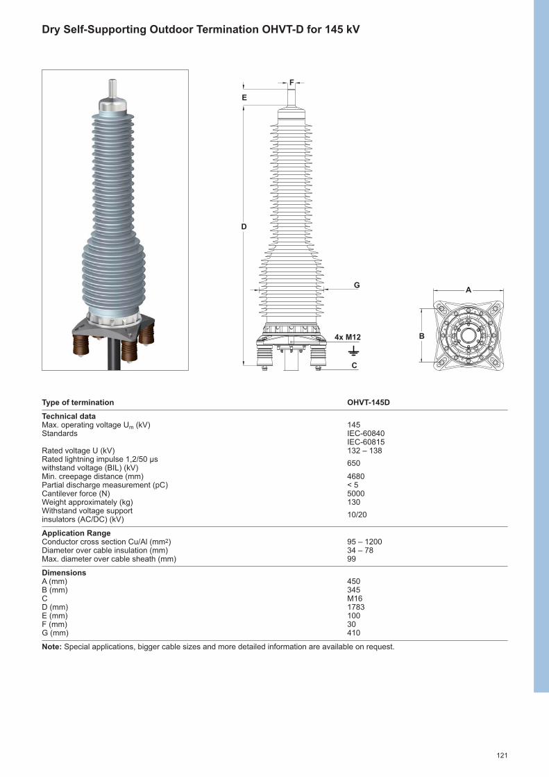
121
Dry Self-Supporting Outdoor Termination OHVT-D for 145 kV
Type of termination OHVT-145D
Technical dataMax. operating voltage Um (kV) 145Standards IEC-60840
IEC-60815Rated voltage U (kV) 132 – 138Rated lightning impulse 1,2/50 µswithstand voltage (BIL) (kV)
650
Min. creepage distance (mm) 4680Partial discharge measurement (pC) < 5Cantilever force (N) 5000Weight approximately (kg) 130Withstand voltage supportinsulators (AC/DC) (kV)
10/20
Application RangeConductor cross section Cu/Al (mm2) 95 – 1200Diameter over cable insulation (mm) 34 – 78Max. diameter over cable sheath (mm) 99
DimensionsA (mm) 450B (mm) 345C M16D (mm) 1783E (mm) 100F (mm) 30G (mm) 410
Note: Special applications, bigger cable sizes and more detailed information are available on request.
F
E
G
C
D
A
B4x M12

122
ApplicationThe dry compact switchgear terminationfor voltage classes up to 245 kV isdesigned to be installed in cable entryhousings of gas-insulated switchgear(GIS). It complies with IEC-62271-209standard, which essentially specifies theinterfaces between the termination andthe switch gear. Therefore the terminationwill fit into all GIS complying with IEC-62271-209. Adapters are available to match the dimensions of wet (oil-filled)type termi nations and older designsspecified in IEC-60859.
The termination operates in SF6 but alsoin insulating liquids like transformer oil. A corona shield at the top of the terminationthen provides the necessary shielding of the terminal.The termination is easily separable andconsists of a plug-in part and an epoxyresin insulator. The insulator can beinstalled by the GIS or transformermanufacturer already at the factorysaving installation time onsite andreducing the risk of contamination of thecable entry housing. In case of shortcable links and due to the short lengthand light weight of the plug-in part it canbe also preinstalled by the cablemanufacturer further reducing the timerequired to install a substation.
Features• Dry interfaces, no oil-filling• Dimensions comply with IEC-62271-209• Pressure-tight resin housing• Operates in SF6 and insulating liquids• Pre-fabricated and factory tested
silicone rubber stress cone• Multi-contact mechanical connector with
shear-head bolts with predeterminedshear torque
• No special tools required to install thetermination
• Isolated cable gland for sectionalization• Type tested according to IEC-60840,
IEC-62067 and IEC-62271-209standards
Dry Compact Switchgear and Transformer Termination PHVS and PHVT for 72 kV up to 245 kV
2
1
3
4
5
6
7
8
Cut-away drawing of PHVS and PHVT1 Corona shield (PHVT only)2 Adapter (optional)3 Mechanical connector4 Resin housing5 Stress cone6 Spring-loaded compression ring7 Fixing ring8 Gland and sealing
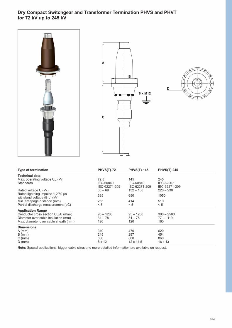
123
Dry Compact Switchgear and Transformer Termination PHVS and PHVT for 72 kV up to 245 kV
Type of termination PHVS(T)-72 PHVS(T)-145 PHVS(T)-245
Technical dataMax. operating voltage Um (kV) 72,5 145 245Standards IEC-60840 IEC-60840 IEC-62067
IEC-62271-209 IEC-62271-209 IEC-62271-209Rated voltage U (kV) 60 – 69 132 – 138 220 – 230Rated lightning impulse 1,2/50 µswithstand voltage (BIL) (kV)
325 650 1050
Min. creepage distance (mm) 255 414 519Partial discharge measurement (pC) < 5 < 5 < 5
Application RangeConductor cross section Cu/Al (mm2) 95 – 1200 95 – 1200 300 – 2500Diameter over cable insulation (mm) 34 – 78 34 – 78 77 – 119Max. diameter over cable sheath (mm) 120 120 160
DimensionsA (mm) 310 470 620B (mm) 245 297 454C (mm) 800 800 860D (mm) 8 x 12 12 x 14,5 16 x 13
Note: Special applications, bigger cable sizes and more detailed information are available on request.
D
C
A
B
6 x M12

124
ApplicationThe joint is a pre-fabricated one-piecedesign for voltage classes up to 245 kV.Polymeric insulated cables of variousdesigns can be adapted with respect to shielding and metal sheath. Thesilicone rubber joint body with integratedgeometrical stress control providesproven electrical function. The jointcomponents combine electricalperformance, stress control and moisturesealing to provide the important functionsrequired for all high voltage products.
Features• Premoulded one-piece joint body• Mechanical connector with shear-head
bolts with predetermined shear torque• Choice of outer sealing and protection
systems• Joint fits on all polymeric cable
constructions• Proven shield continuity concept• Factory-tested silicone rubber body• Special silicone rubber provides perfect
compression force for optimisiedelectrical performance
• Simple assembly• No tension set of push on joint body• Moulded thick outer conductive screen• Geometrical electrical stress control
by moulded conductive deflectors• Type tested according to IEC-60840,
IEC-62067, IEEE-404 and GB-11017Standards
One-piece Joint EHVS-S up to 245 kV
Cut-away drawing of EHVS-S1 Mechanical connector2 Silicone rubber body3 Inner electrode4 Deflector5 Outer electrode6 Copper mesh7 Solderless shield connection8 Sealant/mastic9 Insulating tubes
10 Outer protection with integratedmoisture barrier
Joint shield conductivity• Solderless grounding connection• Typical shield wire cross sections can
be easily connected by eithermechanical or compression connectors
7 8 4 5 2 3 1 6 9 10
Shield break connection
Grounded connection
Straight through connection

125
One-piece Joint EHVS-S up to 245 kV
Type of joint EHVS-145S EHVS-245S
Technical dataMax. operating voltage Um (kV) 145 245Standards IEC-60840 IEC-62067Rated voltage U (kV) 132 – 138 220 – 230Rated lightning impulse 1,2/50 µswithstand voltage (BIL) (kV)
650 1050
Partial discharge measurement (pC) < 5 < 5
Application RangeConductor cross section Cu/Al (mm2) 500 – 1200 300 – 2500Diameter over cable insulation (mm) 56 – 78 77 – 119Max. diameter over cable sheath (mm) 110 140
DimensionsLength (mm) 2400 2600Diameter (mm) 220 280
Screen TreatmentInline √ √Shield break √ √Grounded √ ---
Note: All listed dimensions are standard size to serve the common application of these joints.Special applications, bigger cable sizes and more detailed information are available on request.
Inline joint
Shield break joint

126
ApplicationThe joint is a pre-fabricated three piecedesign for voltage classes up to 170 kV.Polymeric insulated cables of variousdesigns can be adapted with respect to shielding and metal sheath. The siliconerubber joint parts with integratedgeometrical stress control provide provenelectrical function. The joint componentscombine electrical performance, stresscontrol and moisture sealing to providethe important functions required for allhigh voltage products.
Features• Premoulded three piece joint design• Mechanical connector with shear-head
bolts with predetermined shear torque• Joint fits on all polymeric cable
constructions• Proven shield continuity concept• Factory-tested silicone rubber bodies• Special silicone rubber provides perfect
compression force for optimiziedelectrical performance
• Short cut-back dimensions• No special tools required to install the
joint• Cable size transition possible• No tension set of push on joint body• Moulded outer conductive screen• Geometrical electrical stress control
by moulded conductive deflectors• Type tested according to IEC-60840
and IEEE-404 Standards
Tree-piece Joint EHVS-T up to 170 kV
Cut-away drawing of EHVS-T1 Mechanical connector2 Silicone rubber adapter body3 Silicone rubber main body4 Inner electrode5 Deflector6 Outer screen7 Copper mesh8 Solderless shield connection9 Sealant/mastic
10 Insulating tubes11 Outer protection with integrated
moisture barrier
Joint shield conductivity• Solderless grounding connection• Typical shield wire cross sections can
be easily connected by eithermechanical or compression connectors
Grounded connection
Straight through connection
Main joint components• Mechanical connector• Silicone rubber adapter body• Silicone rubber main body
89 65 2 3 1 7 10 114

127
Tree-piece Joint EHVS-T up to 170 kV
Type of joint EHVS-145T EHVS-170T
Technical dataMax. operating voltage Um (kV) 145 245Standards IEC-60840 IEC-60840Rated voltage U (kV) 132 – 138 150 – 161Rated lightning impulse 1,2/50 µswithstand voltage (BIL) (kV)
650 750
Partial discharge measurement (pC) < 5 < 5
Application RangeConductor cross section Cu/Al (mm2) 185 – 1600 240 – 2500Diameter over cable insulation (mm) 43 – 83 60 – 110Max. diameter over cable sheath (mm) 105 112
DimensionsLength (mm) 2000 2000Diameter (mm) 200 250
Screen TreatmentInline √ √Shield break √ √Grounded √ √
Note: All listed dimensions are standard size to serve the common application of these joints.Special applications, bigger cable sizes and more detailed information are available on request.
Inline joint
Shield break joint

128
Tool
s an
d A
cces
sorie
s

129
Tools and Accessories
Gas torch assembly 130
Tool sets 132
Cable preparation tools 133
Miscellaneous tools and accessories 135
Accessories for solderless earth connections 137
Sealing and filler tapes 137

130
Gas torch assembly FH-1630
Nozzles for FH-1630-S Flame Gas SternDiameter consumption length(mm) (kg/h) (mm)
FH-1630-S-BN 28 28 0,46 195FH-1630-S-BN 38 38 0,90 195FH-1630-S-BN 50 50 2,00 195
For PlumbingFH-1630-S-PN 17 17 0,24 195
Torch handleFH-1630-S-HNZFH-1630-S-HSZ
Torch handle with holder and shut-off valvefor use on all FH-1630-S nozzles. HandleHSZ has in addition a pilot/full flame lever.Nozzle connection thread: R 3/8“, rightHose connection thread: R 3/8“, left
Torch handle with piezo ignition, gassupply only while handle is pressed. Nozzle connection: bayonet socking.Hose connection thread: R 3/8“, left
Nozzles for FH-1630-PIE Flame Gas SternDiameter consumption length(mm) (kg/h) (mm)
FH-1630-PIE-BN 28 28 0,46 195FH-1630-PIE-BN 38 38 0,90 195FH-1630-PIE-BN 50 50 2,00 195
For PlumbingFH-1630-PIE-PN 18 18 0,24 210
Torch handle with piezo ignitionFH-1630-PIE
Torch box with nozzles BN28, BN38 andPN17, torch handle HSZ, constantpressure regulator R1, automatic cut-offvalve CV, 4 m long high pressurehose SW4.Weight: 4,8 kgDimensions: 470 x 210 x 74 mm
Torch box with contentsFH-1630-S-MC10
Torch box with nozzles BN28, BN38,BN50 and PN18, torch handle FH-1630-PIE with piezo ignition,safety regulator LGS, 4 m long highpressure hose SW4.Weight: 4,8 kgDimensions: 450 x 210 x 74 mm
Torch box with contentsFH-1630-PIE-MC10
The FH-1630 torch assembly for rapid installation of heat-shrinkable materialsoffers maximum burning efficiency and the best available balance of surfacepreheat. All system components are fully compatible.

131
High pressure hoses Fitted with screw connections for FH-1630 constant pressure regulatorand torch handle.Connection threads: R 3/8“, leftInternal diameter: 4 mmColour: orange
FH-1630-PIE-SW 4 (length: 4 m)FH-1630-PIE-SW 5 (length: 5 m)FH-1630-PIE-SW 10 (length: 10 m)
Torch assemblyFH-1630-S-TS1
Torch assembly of nozzle BN38, torchhandle FH-1630-S-HNZ and 5 m longpressure hose SW5.
Accessories for gas torch assembly FH-1630
Constant pressure regulatorFH-1630-PIE-R1
Applicable on propane gas tanks witha capacity of 5 kg or 11 kg. Threadconnection fits to all FH-1630 highpressure hoses. Gas flow: max. 6 kg/hConstant pressure: 2 bar Hose connection thread: R 3/8“, leftGas bottle connection thread: W 21,8 x 1/14“, left (DIN-Kombi)
Safety regulatorFH-1630-PIE-LGS
The safety regulator with integratedconstant pressure regulator (2 bar, 2 kg/h)and automatic cut-off valve is fittedbetween the hose and the gas bottle.Hose connection thread: R 3/8“, leftGas bottle connection thread: W 21,8 x 1/14“, left (DIN-Kombi)
The automatic cut-off valve is fittedbetween the hoses SW4, SW5 or SW10and the constant pressure regulator andcuts off the gas supply in the event ofdamage to the hose or torch handle.Connection threads: R 3/8“, left
Automatic cut-off valveFH-1630-PIE-CV

132
Tool Sets
Complete tool kitIT-1000-001-CEE02
The tool kit contains all basic tools usually required for the cable preparation andthe installation of accessories. Following tool sets are assembled in a leather case:
Ordering description Contents
IT-1000-003 1 x Wedge positioner for spreading cable cores
1 x Hammer, 300 g1 x Screwdriver, 3,5 mm
IT-1000-005 1 x Screwdriver, 6,5 mm1 x Hacksaw1 x Hacksaw junior
1 x Pipe wrench, 250 mm1 x Side cutter, 160 mm
IT-1000-006 1 x Pincers, 180 mm1 x Blunt nose pliers, 180 mm1 x Scissors, 200 mm
1 x Folding ruler, 2 m1 x Wire brush
IT-1000-0071 x Hook knife 1 x Cable knife 1 x Sharpening stone, 125x100 mm1 x File set, medium size
1 x Control mirror, 100x100 mm1 x Spreader 3 way
IT-1000-008 2 x Core separator 6 x Cleaning tissues1 x Refillable solvent bottle (empty), 0,4 litre
IT-1000-010 1 x Diameter tape, 2 m
IT-1000-011 1 x Scoring tool for easy-strip screens
IT-1000-012 1 x Leather tool case, 400x125x280 mm
1 x Tee-handle spinner wrench, 300 mm1 x Hexagon insert socket for wrenches, 13 mm
IT-1000-015 1 x Hexagon insert socket for wrenches, 17 mm1 x Hexagon insert socket for wrenches, 19 mm1 x Hexagon insert socket for wrenches, 22 mm
The individual tool sets can be also ordered separately.
Cordless impact wrenchIT-1000-033
The ergonomic cordless impact wrench allows safe, fast and convenient installation of mechanical connectors and lugs using shear-head bolts. The wrench can be used forshear-head bolts up to 100 Nm. It is equipped with belt hook with integrated LED worklight and delivered in stable compartmented carrying case.
The content of the case:1 x Cordless impact wrench1 x Battery charger2 x Li-ion battery 3,0 Ah (14,4 V)8 x ½“ hexagonal socket: 10; 13; 16; 17; 19; 22; 24; 27 mm1 x Adapter to ¼” hexagonal drive4 x Allen key insert: H5x65, H6x38, H6x65 and H8x65 mm1 x Installation instruction
Spare parts:IT-1000-033-BAT-LI-ION - battery Li-ion 3,0 Ah (14,4 V) IT-1000-033-CHRG-220V - charger for battery

133
Cable Preparation Tools
Cable knifeEXRM-0607
Cable knife with fixed bladeLength: 175 mm
Ratchet type cutterKR 600
Ratchet type cable cutter for aluminiumand copper conductors, stranded or solidup to 400 mm2.Application range: Ø max. 52 mm
Insulation stripping pliersEXRM-1004
Insulation stripping tool for paper insulated cables.Length: 190 mmApplication range: Ø 15–50 mm
Insulation stripping stringEXRM-0764
Insulation stripping string for plasticinsulated cables.Length: 2000 mm
Hook knifeEXRM-0947
Cable knife for oversheath stripping for cables with an outer diameter > 20 mm.Hook form of the blade ensures an easyand safe dismantling.
Scoring tool for easy strip screensIT-1000-011
Fixed blade scoring tool for easy stripconduct layer.
Ordering description Scriber depth(mm)
IT-1000-011 0,4IT-1000-011-0.6 0,6

134
Designed for insulation removing and oversheath stripping of plastic insulated cables,ranging from 35 mm2 10 kV to 500 mm2 35 kV.The automatic feed (2 steps) and the 0 position, for a radial cut, allow a quick, safe andexact cutting of the cable oversheath and insulation. The special shape of the knife liftsthe sheath at the cutting point and thus prevents damage to any componentsunderneath. Tool is supplied completely with an operating manual in a box.
Application range: Ø 15 - 50 mm, thickness up to 10 mmSpare blade: IT-1000-024-01 (set of 5 pieces)
Designed for screen removing of round plastic insulated conductors with coextrudedand bonded semi-conductive screen. It is continuously adjustable to the core diameterswithin given range. Cutting depth easily changed with a knurled head screw. Deliveredcompletely with operating manual, hexagonal allen key and a spare blade in a tool box.
Application ranges Ordering descriptionIT-1000-017-1 IT-1000-017-2 IT-1000-017-3
Over semi-conductive layer Ø 16-34 mm Ø 19-45 mm Ø 26-48 mmRated Voltages Uo/U (Um) (kV) Cable Cross Section (mm2) according to IEC 502
6 / 10 (12) 25 - 300 70 - 630 120 - 8008,7 / 15 (17,5) 25 - 240 50 - 630 70 - 80012 / 20 (24) 25 - 185 25 - 500 50 - 63018 / 30 (36) 35 - 120 35 - 400 35 - 50020 / 35 (42) 35 - 95 35 - 300 35 - 400
Spare blade: EXRM-1606
Stripping tool for coextruded and bonded cable screens and primary insulation for HV cables. Completely delivered in a heavy-duty plastic case, with operating manualand one set of coated blades.
Ordering description Cable Diameter (mm)min. max.
HVIA-STRIPPER-35/ 90 35 90HVIA-STRIPPER-75/150 75 150
Insulation and oversheath stripping toolIT-1000-024
Screen removal toolIT-1000-017
Stripping toolHVIA-STRIPPER

135
Miscellaneous Tools and Accessories
Cleaning tissuesEPPA-004
Tissues impregnated with water-solublecleaning solution. For cleaning anddegreasing of metal and plastic surfaces.Size: 145 x 140 mm folded to 80 x 60 mmPackaging: 50 pieces in a box
Installation toolIT-1000-019
Tool for holding mechanical connectors in position while tightening the bolts. Length of handle: 205 mmApplication range: Ø 15 - 60 mm
Hexagon insert socketEXRM-1228
Extra long hexagon insert socket wrenchis used for the installation of RICSadapters.Insert socket size: 24 mmLength: 90 mm
Core separatorB 6340B 7060
Wedge core separator made of an impactresistant plastic material. The LV cablecores’ separating with the B 7060 is donein two very simple steps: wedge in andtwist.
Cable Ordering cross section (mm2) description
25–150 B 634050–185 B 7060
Refillable bottle for solventEXRM-0945-0,4
Refillable aluminium bottle with yellow capfor degreasing solution (empty), 0,4 litre.
Core bend-out toolEXRM-2014-CBT-16
Wedge side of the tool used for quickand easy spreading of LV cable cores and integrated claw on the other tool’sside designed for bending out and properpositioning of cable cores for branchjoints.
Application range: 4 -16 mm²Material: highly impact resistantreinforced plastic
Channel pulling toolIT-1000-014
Tool used for installation and securingof closing channels on heat-shrinkablewraparounds such as CRSM, MRSM and RFSM.

136
Fluorosilicone grease EXRM-0956-45
Fluorosilicone grease for installationof RICS insulated T-adapter and RCABstraight adapter system for gas-insulatedswitchgears.
Content: 4,5 ml (6,6 g) in a bagDimensions: 40 x 85 mm
FunnelEPPA-017
Funnel to fill draining oil (MI) cableterminations with insulating oils, i.e. EPPA 016-1-10.
Insulating oilEPPA-016
Insulating oil is used to fill the crutch ofdraining oil cable terminations, e.g. typeIDST and EPKT.
Description Content
EPPA-016-1-10 1,0 literEPPA-016-1-17 1,7 liter
Inflation toolRDSS-IT-16
Inflation tool for RDSS duct seals complete with ON/OFF switch and anautomatic pressure monitoring system.The required CO2 gas cylinders (E7512-0160) must be orderedseparately.
CO2 gas cylinderE7512-0160
Gas cylinder for inflation of RDSSduct seals by installation tool RDSS-IT-16.Each gas cylinder inflates about 5 piecesof RDSS-100.
Content: 16 g of CO2Packaging: 10 cylinders in a box
Assembly lubricantEPPA-064-60
Lubricant for installation of RSTIscreened T-connection system for gas-insulated switchgears.
Content: 60 g in a plastic tube withsponge top and cap closure

137
Roll Springs Constant force roll springs used forsolderless shield and armourconnections.
Ordering Application Diameter (mm) WidthDescription min. max. (mm)
EPPA-034-E 17 29 25EPPA-034-F 30 39 25EPPA-034-G 40 60 25EPPA-034-H 50 75 30
Ligarex pliersIT-1000-004
These special pliers are used fortightening the Ligarex ties. The Ligarexties are used in earth connections ofpaper cables with metal sheaths.
Ligarex ties Ordering LengthDescription (mm)
EXRM-0302-500 500 EXRM-0302-800 800
Sealing and filler tapes
Ordering description Width Thickness Length(mm) (mm) (mm)
S1052-1-500 35 1,0 500
Sealing tape S1052 S1052 is a black; heat activated highflow sealant used for sealing, corrosionprotection and large void filling.
Ordering description Width Thickness Length(mm) (mm) (mm)
EPPA-206-2-1500 50 2,0 1500EPPA-206-4- 250 50 4,0 250
Filler tape EPPA-206 EPPA-206 is a black mastic and mainlyused as filling and shimming tape.
Accessories for solderless earth connections

138

1

Tyco Electronics Raychem GmbHa TE Connectivity Ltd. Company TE Energy Finsinger Feld 185521 Ottobrunn/Munich, Germany
Phone: +49-89-6089-0 Fax: +49-89-6096345
energy.te.com
While TE Connectivity (TE) has made every reasonable effort to ensure the accuracy of the information in this catalog, TE does not guarantee that it is error-free, nor does TE make any other representation, warranty or guarantee that the information is accurate, correct, reliable or current.TE reserves the right to make any adjustments to the information contained herein at any time without notice. TE expressly disclaims all impliedwarranties regarding the information contained herein, including, but not limited to, any implied warranties of merchantability or fitness for a particular purpose. The dimensions in this catalog are for reference purposes only and are subject to change without notice. Specifications aresubject to change without notice. Consult TE for the latest dimensions and design specifications.Raychem, TE Connectivity and TE connectivity (logo) are trademarks.
TE Energy – innovative and economical solutions for the electrical power industry: cable accessories, connectors & fittings, insulators & insulation,surge arresters, switching equipment, street lighting, power measurement and control.
ABOUT TE CONNECTIVITY
TE Connectivity is a global, $14 billion company that designsand manufactures approximately 500,000 products thatconnect and protect the flow of power and data inside theproducts that touch every aspect of our lives. Our nearly100,000 employees partner with customers in virtuallyevery industry—from consumer electronics, energy andhealthcare, to automotive, aerospace and communicationnetworks—enabling smarter, faster, better technologies toconnect products to possibilities.More information on TE Connectivity can be found athttp://www.te.com.
© 2
013
Tyco
Ele
ctr
on
ics
Raych
em
Gm
bH
EP
P 0
50
0 S
EE
2/1
3


