
Siemens Industry, Inc. 5300 Triangle Parkway, Norcross, GA 30092 A5E31166504A-001
Reduced Voltage Controllers Wye-Delta, Part-Winding And Autotransformer Installation, Operation And Maintenance Instructions
E87010-A0117-T004-A4 August, 2012

2 Siemens Industry, Inc. 5300 Triangle Parkway, Norcross, GA 30092 A5E31166504A-001
Hazardous voltage. Will cause death or serious injury. Always de-energize and ground the equip- ment before maintenance. Read and understand this manual before installing, operating or maintaining the equipment. Maintenance should be performed only by qualified personnel. The use of unau- thorized parts in the repair of the equip- ment or tampering by unqualified person- nel may result in dangerous conditions which may cause death or serious injury, or equipment or property damage. Follow all safety instructions contained herein.
SIGNAL WORDS
The signal words “Danger”, “Warning” and “Caution” used in this manual indicate the degree of hazard that may be encountered by the user. These words are defined as:
Danger - Indicates an imminently hazardous situation which, if not avoided, will result in death or serious injury.
Warning - Indicates a potentially hazardous situation which, if not avoided, could result in death, serious injury or property damage.
Caution - Indicates a potentially hazardous situation which, if not avoided, may result in minor or moderate injury. It may also be used to alert against unsafe practices.
QUALIFIED PERSON For the purposes of this manual and product labels, a qualified person is one who is familiar with the installation, construction, operation or maintenance of the equipment and the haz- ards involved. In addition this person has the following qualifications: (a) is trained and authorized to energize,
de-energize. clear, ground and tag cir- cuits and equipment in accordance with established safety practices.
(b) is trained in the proper care and use of
protective equipment such as rubber gloves, hard hat, safety glasses or face shields, flash clothing, etc., in accor- dance with established safety practices.
(c) is trained in rendering first aid.
IMPORTANT
These instructions do not purport to cover all details or variations in equipment, nor to provide for every possible contingency to be met in connection with installation, operation or maintenance. Should further information be desired or should particular problems arise which are not covered sufficiently for the purchaser’s purposes, the matter should be referred to the local Siemens sales office. The contents of this instruction manual shall not become part of or modify any prior or existing agree- ment, commitment or relationship. The sales contract contains the entire obligation of Siemens. The warranty contained in the contract between the parties is the sole warranty of Siemens. Any statements contained herein do not create new warranties or modify the existing warranty.

Siemens Industry, Inc. 5300 Triangle Parkway, Norcross, GA 30092 A5E31166504A-001 3
Table of Contents
1 General Information . . . . . . . . . . . . . . . . . . . . . . . . . . . . . . . . . . . . . . . . . . . . . . . . . . . . . . . . . . . . .4
2 Handling And Installation . . . . . . . . . . . . . . . . . . . . . . . . . . . . . . . . . . . . . . . . . . . . . . . . . . . . . . . . .5
3 Parts And Service . . . . . . . . . . . . . . . . . . . . . . . . . . . . . . . . . . . . . . . . . . . . . . . . . . . . . . . . . . . . . . .6
4 Introduction To Reduced Voltage Controllers . . . . . . . . . . . . . . . . . . . . . . . . . . . . . . . . . . . . . . . . . .7
5 Autotransformer Controllers . . . . . . . . . . . . . . . . . . . . . . . . . . . . . . . . . . . . . . . . . . . . . . . . . . . .8 - 9
6 Wye Delta Controllers . . . . . . . . . . . . . . . . . . . . . . . . . . . . . . . . . . . . . . . . . . . . . . . . . . . . . . .10 - 12
7 Part Winding Controllers . . . . . . . . . . . . . . . . . . . . . . . . . . . . . . . . . . . . . . . . . . . . . . . . . . . . . .13-14
8 Protective Devices . . . . . . . . . . . . . . . . . . . . . . . . . . . . . . . . . . . . . . . . . . . . . . . . . . . . . . . . . . . . .15
9 Maintenance / Start-Up . . . . . . . . . . . . . . . . . . . . . . . . . . . . . . . . . . . . . . . . . . . . . . . . . . . . . .16 - 17
10 Maintenance / Troubleshooting . . . . . . . . . . . . . . . . . . . . . . . . . . . . . . . . . . . . . . . . . . . . . . . . . . .18
11 Preventative Maintenance Checklist . . . . . . . . . . . . . . . . . . . . . . . . . . . . . . . . . . . . . . . . . . . . . . .19

4 Siemens Industry, Inc. 5300 Triangle Parkway, Norcross, GA 30092 A5E31166504A-001
1 General Information
Hazardous voltage. Will cause death or serious injury. To avoid electrical shock or burn, turn off main and control voltages before perform- ing installation or maintenance.
This product contains hazardous voltages. Severe personal injury, death or property damage can result if safety instructions are not followed. Only qualified personnel should work on or around this equipment after becoming thoroughly familiar with all warnings, safety notices, and maintenance procedures con- tained herein. Turn off power supplying this equipment before any adjust- ments, servicing, wiring, parts replacement, or before any act requiring physical contact with electrical working components of this equipment is performed. The successful and safe operation of electrical equipment is dependent upon proper handling, installation, operation and maintenance, as well as upon proper design and manufacture. Failure to follow these installation and maintenance instructions may also lead to the failure and loss of control equipment, as well as damage to other property.
Siemens Reduced Voltage Controllers are built in accordance with applicable provisions of NEMA and ANSI Standards, and the National Electrical Safety Code. These publications and this instruction manual should be thoroughly read and understood prior to beginning any work on this equipment. Qualified Person For the purpose of this manual and product labels, a qualified person is one who is familiar with the installation, construction and operation of the equipment, and the hazards involved. In addition, he has the following qualifications: (a) Is trained and authorized to energize, de-energize, clear,
ground and tag circuits and equipment in accordance with established safety practices.
(b) Is trained in the proper care and use of protective equipment such as rubber gloves, hard hat, safety glasses or face shields, flash clothing, etc., in accordance with established safety practices.
(c) Is trained in rendering first aid. Danger For the purpose of this manual and product labels, DANGER indicates an imminently hazardous situation which, if not avoid- ed, will result in death or serious injury. Warning For the purpose of this manual and product labels, WARNING indicates a potentially hazardous situation which if not avoided, could result in death, serious injury or property damage. Caution For the purpose of this manual and product labels, CAUTION indicates a potentially hazardous situation which, if not avoided, may result in minor or moderate injury. It may also be used to alert against unsafe practices.

Siemens Industry, Inc. 5300 Triangle Parkway, Norcross, GA 30092 A5E31166504A-001 5
2 Handling And Installation
General
Although no special mountings or foundations are normally required, the controller should be mounted in a reasonably level position and adequately secured to prevent shifting. Carefully remove any temporary packing, bracing, or blocking from each device. Operate each movable contact device manu- ally to assure free movement. Remove all traces of foreign mat- ter from all contact surfaces. Check to see that there are no loose connections and that ade- quate clearances are maintained for the installation. All external wiring from the controller must be made in strict accordance with the main connection diagram supplied with the unit and the National Electrical Code. If supplied, the entire current transformer secondary circuit should be checked for continuity of connections, as an open cir- cuit could cause extremely high secondary voltages to be gen- erated. Siemens field service technicians are available for installation and start-up supervision if desired. The cost of this supervisory service is usually offset by a considerable saving in installation time. For details, contact your nearest Siemens Sales Office.
Handling And Lifting
Shipment from the factory is usually accomplished by lag bolt- ing the controller to a wooden skid. These controllers can be moved with a fork lift truck providing the load is balanced and steadied to prevent tipping. Lifting eyebolts or angles are supplied as standard on larger units for use with crane or hoist. Spreader bars should be used when lifting eyebolts are provided. The skid and lifting means should not be removed before instal- lation.
Hazardous voltage. Will cause death or serious injury. To avoid electrical shock or burn, turn off main and control voltages before perform- ing installation or maintenance.
If these instructions are ignored and controller is energized with- out arc chutes in place, the warranty on this equipment is auto- matically voided. Severe damage to controller components or possible injury to personnel may result if contactors and starters are operated without arc chutes in place.
Inspection The controller and all accessory devices are normally shipped in a single package. As soon as it is received, carefully inspect for shortage or damage. If accessory items are a part of the ship- ment thoroughly check each for damage. Recheck entire ship- ment against the shipping manifest. If any shortage or damage is found, immediately notify the local freight agent handling the shipment. Proper notation should be made by the agent on the freight bill to prevent any controversy or delay when a claim is made. Storage The controller should be stored in a dry location at a uniform temperature to prevent condensation. Controllers designed for indoor applications do not have suffi- cient packaging for outdoor storage. Additional packaging for protection from the outside elements and temporary heat to prevent condensation should be installed. Controllers designed for outdoor applications should have space heaters installed with a temporary electrical hookup to prevent condensation.
Do not apply power to the Controller until the Operation and Maintenance Start-Up sections have been studied.

6 Siemens Industry, Inc. 5300 Triangle Parkway, Norcross, GA 30092 A5E31166504A-001
3 Parts And Service
Hazardous voltage. Will cause death or serious injury. To avoid electrical shock or burn, turn off main and control voltages before perform- ing installation or maintenance.
This product contains hazardous voltages. Severe personal injury, death or property damage can result if safety instructions are not followed. Only qualified personnel should work on or around this equipment after becoming thoroughly familiar with all warnings, safety notices, and maintenance procedures con- tained herein. Disconnect and lock-out incoming power and control voltage sources before beginning work on this or any other electrical equipment. Check all control circuit terminals with a voltmeter to make cer- tain that the equipment is totally de-energized. Use only approved high voltage test equipment to check power termi- nals. Do not attempt to measure high voltage with a volt-ohm meter. It is recommended that a safety ground be connected to the power bus after the system has been de-energized, and prior to working on the equipment. Follow the procedure outlined in the pre-energization check section of this manual before power is restored.
For the safety of maintenance personnel as well as others who might be exposed to hazards associated with maintenance activities, the safety related work practices of NFPA 70E, part 11, should always be followed when working on electrical equip- ment. Maintenance personnel should be trained in the safety practices, procedures, and requirements that pertain to their respective job assignments. The customer must establish a periodic maintenance program to ensure trouble-free and safe operation. The frequency of inspection, periodic cleaning and preventive maintenance schedule will depend upon the operating conditions. NFPA Publication 70B “Electrical Equipment Maintenance” may be used as a guide to establish such a program. A preventive main- tenance program is not intended to cover reconditioning or major repair, but should be designed to reveal, if possible the need for such actions in time to prevent malfunctions during operation. The items shown on the preventive maintenance checklist on page 19 should be included in the preventive maintenance program. Parts And Service When ordering parts, always give description and catalog number of part desired and the following information for the controller. Catalog Number Siemens Sales Order Number Item Number Customer Identification Number The above information can be found on the inside of the starter door. If possible, use the part number shown on each compo- nent when requesting repair parts information from your Siemens Sales Office or distributor. To insure that Siemens quality standards are maintained, be sure that genuine Siemens renewal parts are used when refur- bishing the controller. Using non-Siemens replacement parts may affect product warranty. In case of major breakdown, contact the Siemens Sales Office nearest you. Experienced field service personnel are available.
Siemens Industry, Inc. 5300 Triangle Parkway, Norcross, GA 30092 A5E31166504A-001 7
4 Introduction To Reduced Voltage Controllers
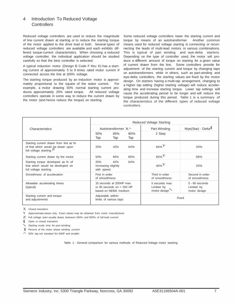
Reduced voltage controllers are used to reduce the magnitude of line current drawn at starting or to reduce the starting torque of the motor applied to the drive load or both. Several types of reduced voltage controllers are available and each exhibits dif- ferent torque-current characteristics. When choosing a reduced voltage controller, the individual application should be studied carefully so that the best controller is selected. A typical induction motor (Design B Code F thru K) has a start- ing current of approximately 5 to 9 times rated motor current if connected across the line at 100% voltage. The starting torque produced by an induction motor is approxi- mately proportional to the square of the stator current. For example, a motor drawing 50% normal starting current pro- duces approximately 25% rated torque. All reduced voltage controllers operate in some way to reduce the current drawn by the motor (and hence reduce the torque) on starting.
Some reduced voltage controllers lower the starting current and torque by means of an autotransformer. Another common means used for reduced voltage starting is connecting or recon- necting the leads of multi-lead motors in various combinations. This is typical of part winding and wye-delta starters. Depending on the type of controller used, the motor will pro- duce a different amount of torque on starting for a given value of current drawn from the line. Some controllers provide for adjustment of the starting current and torque by changing taps on autotransformers while in others, such as part-winding and wye-delta controllers, the starting values are fixed by the motor design. On starters having a multi-tap arrangement, changing to a higher tap setting (higher starting voltage) will reduce acceler- ating time and increase starting torque. Lower tap settings will cause the accelerating period to be longer and will reduce the torque produced during this period. Table 1 is a summary of the characteristics of the different types of reduced voltage controllers.
Characteristics
Reduced Voltage Starting
Autotransformer X^
Part-Winding Wye(Star) - Delta[ 50% 65% 80% Tap Tap Tap
2 Step
Starting current drawn from line as % of that which would be drawn upon full voltage starting.Z
25% 42% 64%
65%Y
33%
Starting current drawn by the motor
50% 65% 80% 65%Y
58%
Starting torque developed as % of that which would be developed on full voltage starting.
25% 42% 64% Increasing slightly with speed.
40%Y
33%
Smoothness of acceleration First in order of smoothness
Third in order of smoothness
Second in order of smoothness
Allowable accelerating times (typical)
15 seconds at 200HP max or 30 seconds on > 200 HP based on NEMA medium
5 seconds max Limited by motor design\
5 - 60 seconds Limited by motor design
Starting current and torque and adjustments
Adjustable within limits of various taps
Fixed
X Closed transition Y Approximate values only. Exact values may be obtained from motor manufacturer Z Full voltage start usually draws between 500% and 900% of full-load current [ Open or closed transition \ Starting mode time for part winding ] Percent of the motor phase winding current ^ 50% tap not standard for 50HP and smaller
Table 1 - General comparison for various methods of Reduced Voltage motor starting

8 Siemens Industry, Inc. 5300 Triangle Parkway, Norcross, GA 30092 A5E31166504A-001
JUM
PE
R
5 Autotransformer Controllers
Reduced Voltage Autotransformer - Size 1 To 7
Refer to the typical schematic diagram for NEMA Size 1 to 7 controllers shown in Figure 1. If 3-wire control is used, connect the momentary start pushbut- ton between terminals 2 and 3; stop pushbutton between 1 and 2. If 2-wire control is used, jumper terminals 2 and 3 and con- nect the remote control contact between terminals 1 and 2.
Sequence Of Operations
The (TR) and (MR) coils are energized by pressing the Start but- ton. As (TR) is energized the timing sequence begins. When relay (MR) is energized, the normally open contacts of (MR) close energizing contactor coil (1S). As soon as (1S) contactor is energized the (2S) contactor coil is energized. Voltage is now being
applied through (2S), the autotransformer, and the (1S) contac- tor to the motor stator windings. The motor accelerates on reduced line voltage determined by the percentage tap used on the autotransformer. After a preset time the timing relay (TR) times out and energizes the (CR1) relay. As (CR1) is energized the (1S) coil is de-energized which in turn energizes the (R) contactor. When the (R) contactor is energized the (2S) contactor is de-energized. This leaves only the (R) contactor energized which puts the motor on full line voltage.
OPTIONAL DISCONNECT
or CIRCUIT BREAKER
Notes: A. Class 36-branch circuit protection, fused disconnect or circuit breaker must be provided by installer since circuit
breaker or fusible disconnect is not factory installed. B. Unwired auxiliary interlocks supplied in control relay (CR2) as specified by customer. C. Unwired auxiliary interlocks are not shown on diagram for the “R” starter. D. For protection of internal control circuit conductors in accordance with the N.E.C., use fuse kit 49MAFB4. E. Remove jumper if thermal protective switch is provided. F. 1, 2, 3CT may be located on line side of contactor depending on circuit design. G. For separate source control connect separate source between TB points 12 and X2.
OL
OL CONNECTIONS FOR OPTIONAL DEVICES
OL
1CT
OL
OL
2CT
OL
3CT
FOR STARTER SIZES 1-4, ICT-3CT
ARE NOT USED
FOR MOTOR
HP SEE CONTROLLER NAMEPLATE
ETM
1LT
(A1) (A2)
4LT
5LT
(A1) (A2)
OPTIONAL DEVICES ARE FURNISHED PER CONTRACT DOCUMENTS
CONNECT VOLTAGE
AS SPECIFIED PER NAMEPLATE
(A1) (A2) (A1)
(A1)
(A2) (95) OL (96)
(A2)
Legend: (Components supplied as required) R - Run Starter 1S - No. 1 Start Contactor 2S - No. 2 Start Contactor CR1 - Time Delayed Relay CR2 - Relay TR - Starting Timer TAS - Auto Transformer Over
Temperature Switch MR - Master Control Relay Ø - Customer Connection Point # - Device Termination Point
Figure 1
Siemens Industry, Inc. 5300 Triangle Parkway, Norcross, GA 30092 A5E31166504A-001 9
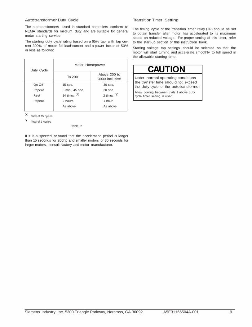
Duty Cycle
Motor Horsepower
To 200
Above 200 to 3000 inclusive
On Off
Repeat
Rest
Repeat
15 sec.
3 min., 45 sec.
14 times X 2 hours
As above
30 sec.
30 sec.
2 times Y 1 hour
As above
Autotransformer Duty Cycle
The autotransformers used in standard controllers conform to NEMA standards for medium duty and are suitable for general motor starting service. The starting duty cycle rating based on a 65% tap, with tap cur- rent 300% of motor full-load current and a power factor of 50% or less as follows:
Transition Timer Setting The timing cycle of the transition timer relay (TR) should be set to obtain transfer after motor has accelerated to its maximum speed on reduced voltage. For proper setting of this timer, refer to the start-up section of this instruction book. Starting voltage tap settings should be selected so that the motor will start turning and accelerate smoothly to full speed in the allowable starting time.
Under normal operating conditions the transfer time should not exceed the duty cycle of the autotransformer. Allow cooling between trials if above duty cycle timer setting is used.
X Total of 15 cycles Y Total of 3 cycles
Table 2
If it is suspected or found that the acceleration period is longer than 15 seconds for 200hp and smaller motors or 30 seconds for larger motors, consult factory and motor manufacturer.

1
Siemens Industry, Inc. 5300 Triangle Parkway, Norcross, GA 30092 A5E31166504A-001
6 Wye Delta Controllers
Reduced Voltage Wye-Delta Open And Closed Transition
These controllers are applicable only to motors wound for wye- delta starting and with all six leads brought out into the motor junction box. Motors should be suitable for starting with wind- ings in wye connection and normal running with windings in delta connection. Such motors would normally be marked with locked rotor KVA Code A.
Open Transition
Refer to the typical schematic diagram shown in Figure 2. If 3-wire control is used, connect the momentary start pushbut- ton between terminals 2 and 3; stop pushbutton between 1 and 2. If 2-wire control is used, jumper terminals 2 and 3 and con- nect a remote control contact between terminals 1 and 2.
Sequence Of Operation - Open Transition Wye Delta (Sizes 1 - 7) Pressing the start button energizes the (CR1) relay, (TR) timer, and (MR) relay. As soon as (CR1) and (MR) are energized the normally open contacts close energizing the (S) contactor. With (S) contactor energized the (1M) contactor energizes. The (S) and (1M) contactors remain energized while timer (TR) times out. When the timing sequence ends (CR1) is de-energized which opens the (CR1) contact, de-energizing the (S) contactors. As soon as the (S) contactors is de-energized the (2M) contac- tor is energized which connects the circuit to the motor in Delta. Pressing stop, or overload relay trip, will de-energize all contac- tors and remove the motor from the line. The wye-delta starter overload relays are connected in the motor phase circuits in series with the (1M) contactor. Therefore, the overload relay current is 58% of the motor line current. See page 15 for setting instructions.

Siemens Industry, Inc. 5300 Triangle Parkway, Norcross, GA 30092 A5E31166504A-001 11
OPTIONAL
DISCONNECT OR
CIRCUIT BREAKER
(A1) (A2)
CONNECTIONS FOR OPTIONAL DEVICES
(A1) (A2)
(A1) (A2)
H3 H2 CONNECT VOLTAGE
ETM
AS SPECIFIED PER NAMEPLATE
1LT
4LT
(A1) (A2) (95) (96) 5LT
(A1) (A2)
OPTIONAL DEVICES ARE FURNISHED PER CONTRACT DOCUMENTS
Legend Ø - Customer Connection Point 1M - First Main Contactor 2M - Second Main Contactor S - Shorting Contactor MR - Master Control Relay CR1 - Time Delayed Relay CR2 - Relay TR - Timer OL - Main Starter O/L Relay (#) - Device Termination Point
Notes: A. Class 36-branch circuit protection, fused disconnect or circuit breaker
must be provided by installer since circuit breaker or fusible disconnect is not factory installed.
B. For protection of internal control circuit conductors in accordance with the N.E.C., use fuse kit 49MAFB4.
C. Set TR for transition time required.
D. For separate control voltage connect source to terminals 1 and X2.
E. 2CT may be located on line side of contactor depending on circuit design.
F. Unwired auxiliary interlocks are not shown on diagram for the 1M starter.
Figure 2

1
Siemens Industry, Inc. 5300 Triangle Parkway, Norcross, GA 30092 A5E31166504A-001
Closed Transition - Wye Delta Refer to the typical schematic diagram shown in Figure 3. If 3-wire control is used, connect the momentary start pushbut- ton between terminals 2 and 3; stop pushbutton between 1 and 2. If 2-wire control is used, jumper terminals 2 and 3 and con- nect a remote control contact between 1 and 2. Closed transition wye-delta controllers contain all the compo- nents used in open-transition plus a 3-pole transition contactor (1A) a set of resistors (RES) to maintain continuity of the motor connection to the line during transition. As in open-transition starting, pressing the start button energizes the (MR) relay, and (TR) timer. Relay (CR1) is energized as soon a power is applied to the control circuit. As soon as (MR) relay is energized (S) contactor is energized and in turn (1M) contactor is energized. At the point of transition the timed contact (TR) opens, de-energizing relay (CR1). When (CR1) is de-energized
OPTIONAL DISCONNECT
OR CIRCUIT BREAKER
contactor (1A) is energized which in turn de-energizes the (S) con- tactor. With (1A) contactor energized the transition resistors are connected in wye (parallel) with the motor windings. A normally closed auxiliary contact of (S) closes and energizes contactor (2M). As soon as (2M) is energized a normally closed auxiliary contact opens removing power from contactors (1A) and (S). With (2M) energized the resistors are bypassed forming the final delta connection of the motor to the line. Note: Transition Timer Setting
The timing cycle of the transition timing relay (TR) should be set to obtain transfer after the motor has accelerated to its maximum speed on reduced voltage. For proper setting of this timer, refer to the start-up section of this instruction book.
Legend Ø - Customer Connection Point 1M - First Main Contactor 2M - Second Main Contactor S - Shorting Contactor 1A - Resistor Contactor MR - Master Control Relay CR1 - Time Delayed Relay CR2 - Relay TR - Timer OL - Main Starter OL Relay (#) - Device Termination Point
(A1) (A2)
(A1) (A2)
(A1) (A2)
(A1) (A2)
H3 H2 CONNECT VOLTAGE
AS SPECIFIED PER NAMEPLATE
(A1) (A2)
(A1) (A2)
Notes: A. Class 36-branch circuit protection, fused dis-
connect or circuit breaker must be provided by installer since circuit breaker or fusible dis- connect is not factory installed.
B. For protection of internal control circuit con- ductors in accordance with the N.E.C., use fuse kit 49MAFB4.
C. Set TR for transition time required.
D. For separate control voltage connect source to terminals 1 and X2.
E. 2CT may be located on line side of contactor depending on circuit design.
F. Unwired auxiliary interlocks are not shown on diagram for the 1M starter.
CONNECTIONS FOR OPTIONAL DEVICES
ETM
1LT
4LT
5LT
Figure 3
OPTIONAL DEVICES ARE FURNISHED PER CONTRACT DOCUMENTS

Siemens Industry, Inc. 5300 Triangle Parkway, Norcross, GA 30092 A5E31166504A-001 13
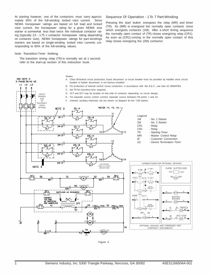
7 Part Winding Controllers
Reduced Voltage Part-Winding
Part-winding controllers are applicable only to induction motors having stator windings divided into two or more equal parts with the terminals of each part available for external connection. Since every two-winding motor is not necessarily suitable for part-winding starting, the applicability to a particular motor should be checked with the motor manufacturer. Refer to the typical schematic diagram shown Figure 4. Upon starting, contactor (1M) closes, connecting one winding, or one half of the motor to the incoming line. The current drawn is approximately 65% of that which would be drawn if the whole motor were connected to the incoming line. (Actual current drawn is a function of motor design). Correspondingly, less than half of the motor starting torque is pro- duced. After a short time delay of approximately 1-5 seconds, con-
tactor (2M) closes, thus connecting the full motor to the incoming line. Part winding controllers are inherently closed transition. Part-winding controllers are generally of the increment type in that the motor may not begin to accelerate on the first step. The current drawn from the incoming line of a part-winding motor at the first step is typically 65% of the full winding locked rotor cur- rent. When the transition to the second step occurs the current will rise to a value equal to or slightly less than the full--winding locked rotor current, depending on whether or not the motor has started to rotate. However, the maximum value is reached in two increments separated by a short time interval which is suf- ficient to meet some power company requirements. During the running condition, each contactor is carrying one-half of the motor full load current. See page 15 for the overload relay setting instructions.
1
Siemens Industry, Inc. 5300 Triangle Parkway, Norcross, GA 30092 A5E31166504A-001
At starting however, one of the contactors must carry approxi- mately 65% of the full-winding locked rotor current. Since NEMA horsepower ratings are based on full load and locked rotor current, the horsepower rating for a given NEMA size starter is somewhat less than twice the individual contactor rat- ing (typically 1.5 - 1.75 x contactor horsepower rating depending on contactor size). NEMA horsepower ratings for part-windings starters are based on single-winding locked rotor currents cor- responding to 65% of the full-winding values.
Note: Transition Timer Setting
The transition timing relay (TR) is normally set at 1 second; refer to the start-up section of this instruction book.
Sequence Of Operation - 1 To 7 Part Winding Pressing the start button energizes the relay (MR) and timer (TR). As (MR) is energized the normally open contacts close which energizes contactor (1M). After a short timing sequence the normally open contact of (TR) closes energizing relay (CR1). As soon as (CR1) coming in the normally open contact of this relay closes energizing the (2M) contactor.
CIRCUIT BREAKER
(1CB) OR
DISCONNECT (1DISC)
OPTIONAL
Notes: A. Class 36-branch circuit protection, fused disconnect or circuit breaker must be provided by installer since circuit
breaker or fusible disconnect is not factory installed. B. For protection of internal control circuit conductors in accordance with the N.E.C., use fuse kit 49MAFB4. C. Set TR for transition time required. D. 2CT and 5CT may be located on line side of contactor depending on circuit design. E. For separate source control connect separate source between TB points 1 and X2. F. Unwired auxiliary interlocks are not shown on diagram for the “1M starter.
Legend 1M - No. 1 Starter 2M - No. 2 Starter CR1 - Relay CR2 - Relay TR - Starting Timer MR - Master Control Relay Ø - Customer Connection (#) - Device Termination Point
FOR STARTER SIZES 1-4, 1CT-6CT
ARE NOT USED
CONNECTIONS FOR OPTIONAL DEVICES
(A1) (A2)
(A1) (A2)
H1 H3 H2 H4 1LT
X1 X2
(A1) (A2)
4LT
5LT
(A1) (A2)
OPTIONAL DEVICES ARE FURNISHED PER
CONTRACT DOCUMENTS
Figure 4
Siemens Industry, Inc. 5300 Triangle Parkway, Norcross, GA 30092 A5E31166504A-001 15
8 Protective Devices
Overload Protection
Protection from motor overload during the starting and running period is provided by the overload relay (OL). It provides pro- tection against overloads and momentary surges but does not protect against short circuit fault currents. For protection against the latter, high interrupting capacity fuses or circuits breakers should be installed ahead of the controller, per N.E.C. requirements.
Overload protection consists of three-pole overload relay(s). The 3 phase overload relay provides outstanding motor protection including single phase protection and an adjustable setting with- out changing of heaters. The adjustment dial should be set from actual motor full load current in accordance with the overload relay adjustment instructions using the overload factors of 58% for wye-delta or 50% for part winding. For size 5 through 7 starters, three separately mounted current transformers are provided and the overload relay is indirectly powered from these CT secondaries. Set the overload relay dial setting to the FLA of the motor for solid state overload. Self-powered solid-state overload relays generate their own run- ning power and do not need a separate source of 120V to power the circuit board. The overload also provides phase loss protec- tion for the motor by tripping within three seconds when there is a complete loss of one phase of the three phase motor branch
circuit. Each overload has a current adjustment range with the adjustment dial reading out in motor full load amps (FLA). In addition to the markings on the dial, there are audible clicks which allow for extremely fine tuning. Note that while thermal overloads require a heater selection based on a relatively wide range, these overloads have many clicks covering the same ampere range. For overload relays other than solid state overloads, divide the motor full load amps by the current transformer ratio. For exam- ple, the ratio of a 300/5 ct is 60/1. Divide the FLA by 60 to get the current value that the overload will actually see. Note: The overload relay is a NEMA Class 10, 20 design and will trip within 10 to 20 seconds at a current of 600% of dial setting. See overload relay instructions for motor service factor require- ments before setting the overload relays. Mechanical Sequence Interlock A mechanical sequence interlock is provided on all autotrans- formers and wye-delta controllers to prevent the simultaneous closing of both starting and running contactors. Optional Protective Devices Power monitor relays, ground fault relays, over-under current relays, etc., may require adjustments prior to start-up. Refer to the instruction sheets provided with each device for proper set- ting/resetting.
1
Siemens Industry, Inc. 5300 Triangle Parkway, Norcross, GA 30092 A5E31166504A-001
9 Maintenance / Start-Up
Controller Start-Up
Complete the installation section of this instruction book prior to beginning the start-up procedures below.
Starting Limitations
With full-voltage starting, a squirrel-cage motor can at the instant of energization draw from four to thirteen times normal running current, depending on the design characteristics of the motor. Many public utilities place current surge limitations on electrical equipment connected to their system networks. These system limitations, which are based on network stability and capacity, can take the form of: 1. A maximum allowable horsepower that can be started direct-
ly across the line; above this horsepower, a limit in percent of full-load current may be set for reduced-voltage starting.
2. A maximum rate of change of line current or a maximum ampere increase per starting step may be specified.
3. A maximum amperage per motor or per horsepower may be set.
In all questionable applications, the user should check with the local utility for line limitations. Checking these limitations often helps to determine the best method of reduced-voltage starting for a specific application. Also, the user should analyze his own distribution system to determine the effects of current and voltage fluctuations from starting of a large motor. Light flicker, malfunction of voltage sensitive equipment, and actuation of protective devices on other equipment, which might throw the system out of service, are considerations. Installation site feeder, branch circuit length, conductor size, types and starting voltage drop may also be an application limi- tation. Minimum equipment operating voltage must be main- tained for motor(s) and controllers. Motor starter type selections and the installation adjustments of reduced voltage types affect starting inrush currents and result- ing voltage drop. In some applications, full-voltage starting torques might damage belt or gear drives, couplings, or the driven loads. The above considerations can dictate the use of reduced-volt- age controllers. The term “reduced-voltage controllers” is applied to all controllers other than those of the across-the-line type. Thus the term includes part-winding controllers, even though full voltage is actually applied to half of the motor termi- nals. As developed above, the real purpose of reduced-voltage controllers is to reduce the current applied to or the torque developed by a motor upon starting. An important fact to keep in mind when applying reduced-volt- age starters is that when the voltage applied to motor terminals is reduced, the current drawn by the motor and the torque developed by the motor are also reduced. The torque of an induction motor is proportional to the square of the rotor current and therefore, approximately proportional to the square of the stator current.
Regardless of whether reduced current or reduced torque is more important in a given application, the two cannot be sepa- rated. One follows the other. The utility supply must be capable of maintaining the line volt- age during both the reduced voltage starting period and while the controller is in the run status. The minimum supply trans- former KVA size should be at least 2 times the motor horse- power. Incoming motor feeder or motor branch circuit conduc- tors must be properly sized per applicable NEC and local code requirements. Power feed should have a disconnect means and be protected against overcurrent, ground and short circuit faults per NEC. The line voltage must not drop below the operating coil voltage range of the controller’s contactors and control circuit devices. Contactors and control circuit devices operating at line voltage must not be allowed to drop below 85% of the coil’s rated volt- age. Supply line voltage for contactors and control power trans- formers must not drop below 90% of the transformer primary rated voltage. Voltage drops below these limits may cause con- tactor chatter and could result in contactor burnout and damage to the controller. Another source for possible contactor chatter is a faulty remote input control signal(s). The line voltage should also not exceed the upper coil voltage limit of 110% of the coil’s rated voltage.
Multiple Voltage Sources Can cause death or serious injury or property damage. Turn off and lock out all power to this equipment before servicing.
Perform the following steps to start wye-delta and autotrans- former controllers: 1. Disconnect and lockout all source voltages applied to the
controller. 2. Continuity check controller load circuit for shorts to ground
and between phases. 3. Check motor leads for correct connections per motor and
controller diagrams. Note: For wye-delta starters requiring motor rotation reversal,
interchange two lines at the input to the controller. 4. When applicable, set the circuit breaker instantaneous trip
dial(s) in accordance with the instructions provided on the breaker trip setting label located on the controller door. The initial setting should start at 700% of full load amperes and may be increased per label instructions.
5. Calculate and set the overload dial setting per the instruc- tions contained in the overload relay label located on the controller door next to the overload relay reset button. For autotransformer starters, refer to overload instruction sheet.
6. If motor acceleration time has been provided, set the tran- sition timer (TR) to two (2) times this value. This value can be used as a starting point. Do not exceed 30 seconds for autotransformer controllers and 60 seconds for wye-delta controllers.
Siemens Industry, Inc. 5300 Triangle Parkway, Norcross, GA 30092 A5E31166504A-001 17
7. Ensure all personnel are clear of the motor and its associat- ed machinery.
8. Ensure the controller power disconnect device is in the “Off” position. Apply feeder power to the controller disconnect and measure the incoming line voltages, note the reading. Verify that the control power transformer (CPT) voltage con- nections and the coil voltage rating for the contactors and control circuit devices are of the correct voltage per the schematic diagram. Note: The motor should be started under minimal loading conditions. Ensure dampers are closed and unloading valves are open, etc.
9. Connect a voltmeter to the load side of the disconnect device. This will allow monitoring of the line voltage for any drop during start. This value must not fall below the voltage limits described previously.
10. Connect a clamp on ammeter to a motor lead or use a tachometer to monitor motor speed. This will allow detec- tion of the motor speed.
11. Apply power to the controller by turning on the controller disconnect device.
Hazardous voltage. Will cause death or serious injury. To avoid electrical shock or burn, turn off main and control voltages before perform- ing installation or maintenance.
12. Apply the start signal to the controller while observing the
line voltage and the ammeter (or tachometer). Check motor for correct rotation. Record the time from start until the motor current falls off rapidly. If this occurs, the transition timer (TR) is set too short. Stop the motor and set the (TR) timer to a longer time. Restart the motor and note the time until the motor reaches full speed. If the transition timer is set too long, reset the timer (TR) to a value 20% longer than the time required to reach full motor speed. Continue this procedure until the desired results are obtained. The line voltage must not drop below the 85% as mentioned previ- ously. If this occurs, the utilities must be consulted to increase power sources. Note: For autotransformer controllers, the required time to reach operating speed can be reduced by changing the auto- transformer taps to a higher percentage of the line voltage. The capability of the utility to maintain the voltage at the higher tap setting must be evaluated.
13. Upon completion of proper start-up, record the time setting, remove test equipment and secure door.
Perform the following steps to start part-winding controller:
1. Disconnect and lockout all source voltages applied to the controller.
2. Continuity check controller load circuit for shorts to ground and between phases.
3. Check motor leads for correct connections per motor and controller diagrams.
4. When applicable, set the circuit breaker instantaneous trip dial(s) in accordance with the instructions provided on the breaker trip setting label located on the controller door. The initial setting should start at 700% of full load amperes and may be increased per label instructions.
5. Calculate and set the overload dial setting per the instruc- tions contained in the overload relay label located on the controller door next to the overload relay reset button or refer to overload instruction sheet.
6. Set the time (TR) to 1 second. Note: Part-winding starters divide the starting inrush current into two increments. Part-winding motors do not normally reach full speed in the starting mode. Timer settings greater than 2 to 3 seconds may result in overload relay tripping on start-up.
7. Ensure all personnel are clear of the motor and its associat- ed machinery.
8. Ensure the controller power disconnect device is in the “Off” position. Apply feeder power to the controller disconnect and measure the incoming line voltage, note the reading. Verify that the control power transformer (CPT) voltage con- nections and the coil voltage rating for the contactors and control circuit devices are of the correct voltage per the schematic diagram. Note: The motor should be started under minimal loading conditions. Ensure dampers are closed and unloading valves are open, etc.
9. Connect a voltmeter to the load side of the disconnect device. This will allow monitoring of the line voltage for any drop during start. This value must not fall below the voltage limits described previously.
10. Apply power to the controller by turning on the controller dis- connect device.
11. Apply the start signal to the controller while observing the line voltage. Check motor for correct rotation. The line volt- age must not fall below 85% as mentioned previously. If this occurs, the utilities must be consulted to increase the power source.
12. Upon completion of proper start-up, remove the test equip- ment and secure door.
Hazardous voltage. Can cause death or serious injury. To avoid electrical shock or burn, turn off main and control voltages before perform- ing installation or maintenance.

1
Siemens Industry, Inc. 5300 Triangle Parkway, Norcross, GA 30092 A5E31166504A-001
10 Maintenance/Troubleshooting
Hazardous voltage. Will cause death or serious injury. To avoid electrical shock or burn, turn off main and control voltages before perform- ing installation or maintenance.
Whenever assistance is desired from Siemens personnel, please contact the nearest Siemens Sales Office. All informa- tion required under the “Maintenance, Parts and Service”, sec- tion of this instruction must be given.
Listed below are possible trouble areas with possible causes.
Control Fuses Opened Î Check for shorted wires (frayed or bare wires shorted to
ground or together) or shorted coils Î Check for jammed or binding contactor/relay contact carriers
Motor Fails To Accelerate Î Check for low voltage or single phasing Î Check for proper operating sequence of starter Î Check for motor loading that is too high Î Check motor leads for proper connections
Starter Fails To Operate Î Check protective devices and settings. Some devices must
be reset manually, and also may require time delay. Î Check for proper operation/wiring of local remote pilot
devices Î Check for loose or open control wiring Î Check for open coils Î Check for presence of proper line and control voltages
Noisy Or Chattering Magnets Î Check for low voltage Î Check for dirty contactor magnet face Î Check for worn parts Î Check device signal controlling the coil for chatter.
Welded Contacts Î Check for abnormal currents or short circuits Î Check for repeated jogging or inching Î Check for weak contact springs Î Check for low voltage during starting Î Check for momentary power interruptions Î Check for chattering of local/remote control signals Overload/Breaker Tripping, Main Fuses Opening Î Check for short circuits and loose power connections Î Check for single phasing or phase unbalance
Î Check starting current, running current, and motor acceler- ating time against overload settings
Î Check for high ambient temperature within enclosure Î Check for proper fuse type/sizing and circuit breaker trip unit
selection and adjustment Abnormal Heat Î Check for loose connections/proper terminations and wire
size Î Check for excessive recycling of starter Î Check for abnormal currents and low voltage
Resistor Failure Î Check for proper sequence and timing
Î Check for proper mechanical and electrical interlock opera- tion
Î Check for excessive recycling of starter Î Check for loose power and control connections

Siemens Industry, Inc. 5300 Triangle Parkway, Norcross, GA 30092 A5E31166504A-001 19
11 Maintenance Preventative Checklist
Failure to properly maintain the equipment can result in severe personal injury and product failure. The instructions contained herein should be carefully reviewed, understood and followed. The following maintenance procedures must be performed regularly:
This checklist does not represent an exhaustive survey of main- tenance steps necessary to insure safe operation of the equip- ment. Particular applications may require further procedures. Should further information be desired or should particular prob- lems arise which are not covered sufficiently for the purchaser’s purposes, the matter should be referred to the local Siemens Sales Office.
Check
Item
Operation
Dust
Clean
Rust and corrosion
Clean - report if excessive
Connections
Tighten electrical connections, look for discoloration of any copper current carrying parts.
Nuts and bolts
Check mechanical connections.
Fuse clips, bolt connection clamps
Check for spring clip pressure, tightness of clamps.
Fuse ferrules
If copper, polish; check for loose ferrules and proper fuse size.
Coils
Check for any signs of overheating or mechanical injury.
Magnets
Clean faces, check for mechanical binding.
Overload relays
Check settings in accordance with overload instructions.
Arc chutes
Check for breaks and excessive burning. Make sure arc chutes are set firmly in place.
Relays
Clean and check for mechanical binding and sticking Check contacts.
Resistors
Check for signs of overheating. If equipped with sliders, tighten.
Contacts
Check for wear. Replace if excessive. Do not file or dress.
Hazardous voltage. Will cause death or serious injury. To avoid electrical shock or burn, turn off main and control voltages before perform- ing installation or maintenance.
Dangerous voltages are present in the equipment which can cause severe personal injury and product failure. Always de- energize and ground the equipment before maintenance. Maintenance should be performed only by qualified personnel. The use of unauthorized parts in the repair of the equipment or tampering by unqualified personnel will result in dangerous con- ditions which can cause severe personal injury or equipment damage. Follow all safety instructions contained herein.

2
Siemens Industry, Inc. 5300 Triangle Parkway, Norcross, GA 30092 A5E31166504A-001
Notes

Siemens Industry, Inc. 5300 Triangle Parkway, Norcross, GA 30092 A5E31166504A-001 21
Notes

Siemens Industry, Inc. 5300 Triangle Parkway, Norcross, GA 30092 A5E31166504A-001
Siemens Industry, Inc. 5300 Triangle Parkway Norcross, GA 30092 Toll Free: 1-800-333-7421 Internet:www.usa.siemens.com/controls © Siemens Industry Inc. 2010 Siemens Industry Inc. , U.S.A.
E87010-A0117-T004-A4 Subject to change without prior notice
Printed in the U.S.A.


