
Rural Sustainable Drainage Systems A Practical Design and Build Guide for Scotland’s Farmers and Landowners
Helping to protect Scotland’s most valuable resource

Published by CREW – Scotland’s Centre of Expertise for Waters. CREW connects research and policy,
delivering objective and robust research and expert opinion to support the development and implementation
of water policy in Scotland. CREW is a partnership between the James Hutton Institute and all Scottish Higher
Education Institutes supported by MASTS. The Centre is funded by the Scottish Government.
This document was produced by:
Alison Duffy1, Stewart Moir2, Neil Berwick1, John Shabashow 1, Brian D’Arcy1, Rebecca Wade1
1Abertay University,
Bell Street, Dundee
DD1 1HG
2Moir Environmental Ltd,
7 Alloway Place, Ayr
KA7 2AA
Please reference this document as follows: Duffy, A. Moir, S. Berwick, N. Shabashow, J. D’Arcy, B. Wade R.
(2016). Rural Sustainable Drainage Systems: A Practical Design and Build Guide for Scotland’s Farmers and
Landowners. CRW2015/2.2. Available online at: crew.ac.uk/publications
Dissemination status: Unrestricted
All rights reserved. No part of this publication may be reproduced, modified or stored in a retrieval system
without the prior written permission of CREW management. While every effort is made to ensure that the
information given here is accurate, no legal responsibility is accepted for any errors, omissions or misleading
statements. All statements, views and opinions expressed in this paper are attributable to the author(s) who
contribute to the activities of CREW and do not necessarily represent those of the host institutions or funders.
Cover photographs courtesy of: Alison Duffy, UWTC, Abertay University and Stewart Moir, Moir
Environmental Ltd.

Contents PART 1 - INTRODUCTION
WHAT ARE RURAL SUSTAINABLE DRAINAGE SYSTEMS (RURAL SUDS)? ............................................................................................................1
HOW WILL RURAL SUDS HELP MY BUSINESS? ..............................................................................................................................................2
PART 2 - RURAL SUDS EXPLAINED
RURAL SUDS - FUNDING OPPORTUNITIES FOR SCOTTISH FARMERS ..................................................................................................................4
RURAL SUDS – FUNDED MEASURES THAT REDUCE DIFFUSE POLLUTION ............................................................................................................5
RURAL SUDS - WHEN TO USE THEM ..........................................................................................................................................................6
RURAL SUDS – JARGON .........................................................................................................................................................................7
RURAL SUDS – TREATMENT TRAIN ...........................................................................................................................................................7
PART 3 - ASSESSMENT SELECTION DESIGN
RURAL SUDS – HOW TO ASSESS, SELECT AND DESIGN ..................................................................................................................................9
PART 4 - STEADING
WHERE TO USE RURAL SUDS AT THE STEADING .........................................................................................................................................10
STEADING - SELECTION TABLE ................................................................................................................................................................12
STEADING DIAGRAM - SOURCES OF POLLUTION AND MANAGEMENT SOLUTIONS ...............................................................................................13
STEADING - SELECTION CHART A ............................................................................................................................................................14
STEADING - SELECTION CHART B.............................................................................................................................................................15
STEADING - SIZING CRITERIA ..................................................................................................................................................................16
PART 5 - FIELD
WHERE TO USE RURAL SUDS IN THE FIELD ................................................................................................................................................18
FIELD DIAGRAM - SOURCES OF POLLUTION AND MANAGEMENT SOLUTIONS .....................................................................................................19
FIELD SELECTION CHART .......................................................................................................................................................................20
FIELD SIZING CRITERIA ..........................................................................................................................................................................21
PART 6 - GENERAL DESIGN GUIDANCE
COLLECTION AND TRANSFER OF RUNOFF ..................................................................................................................................................22
LANDSCAPING, HABITAT AND BIODIVERSITY ENHANCEMENT..........................................................................................................................23
PART 7 - SPECIFICATION SHEETS
SWALE ..............................................................................................................................................................................................25
SEDIMENT TRAP ..................................................................................................................................................................................29
POND ...............................................................................................................................................................................................33
WETLAND .........................................................................................................................................................................................37
SEDIMENT TRAP BUND .........................................................................................................................................................................42
PART 8 - MAXIMISING THE BENEFITS OF RURAL SUDS ................................................................................................ 46
PART 9 - OTHER MANAGEMENT OPTIONS .................................................................................................................. 47
PART 10 - CASE STUDIES
FIELD SEDIMENT TRAP BUND IN FIFE (1) ..................................................................................................................................................49
FIELD SEDIMENT TRAP BUND IN FIFE (2) ..................................................................................................................................................50
STEADING SWALE AND CONSCTRUCTED FARM WETLAND NEAR DUMFRIES .......................................................................................................51
FIELD SEDIMENT TRAP BUND AND POND IN ANGUS ....................................................................................................................................52
PART 11 - USEFUL INFORMATION ............................................................................................................................... 53
PART 12 - ACKNOWLEDGEMENTS ..........................................................................................................................54

PART 1 – INTRODUCTION
Page | 1
What are Rural Sustainable Drainage Systems (Rural SuDS)? Soil cultivation, manure / fertiliser applications and chemical spraying can all contribute to diffuse
pollution from agricultural land. Rainfall runoff from farm roads, tracks, yards and dusty roofs are
also potential sources of diffuse pollution. Whilst many changes in farming practice have dealt with
these sources of pollution there still remains instances where small amounts escape from a
farmyard into a nearby ditch or where sediment laden overland field flows make their way into a
ditch or burn, river or natural wetland and finally the sea. This not only has cost implications for a
farmer but these incidents across a catchment have a huge impact on our water environment.
Rural Sustainable Drainage Systems (Rural SuDS) will reduce agricultural diffuse pollution impacts
as they are physical barriers that treat rainfall runoff. They are low cost, aboveground drainage
structures that capture soil particles, organic matter, nutrients and pesticides before they enter our
water environment. Rural SuDS for steadings prevent blockages in drains and ditches. They
contribute to good environmental practice and farm assurance schemes. In fields they can be used
for returning fertile soil back to farmland and will help your business become more resilient to the
impacts of climate change. Trapping soils, organic matter and nutrients means that valuable assets
can be reclaimed – recent studies indicate savings of £88 per hectare per year!
This Design and Build guide can be used by farmers and land managers who wish to apply for an
Agri-Environmental Climate Scheme (AECS) grant or not. You may have a diffuse pollution issue
outwith AECS objectives but you should still consider using Rural SuDS to reduce diffuse pollution.
A Rural SuDS Pond in South East Scotland
This guide will help you select, design and build the most suitable Rural SuDS for your farm and
explains how to look after the systems. It also promotes the wider benefits such as coping with
extreme weather related to climate change, localised flood prevention and enhancing biodiversity.
Other sustainable land management options that you can consider are provided in Part 9. Case
studies in Part 10 illustrate how these practices have been successfully applied around Scotland.
Imag
e ©
Alis
on
Du
ffy

PART 1 – INTRODUCTION
Page | 2
How will Rural SuDS help my Business? Where rainfall runoff enters slurry storage
systems unnecessarily, then Rural SuDS can
be used to collect and treat the runoff from
roofs and general yards. Diverting roof and
general yard runoff away from your slurry
store means that not only will you increase
slurry storage capacity but the slurry will have
a higher dry matter content thereby
increasing nutrient concentration and
fertiliser value per volume spread on land.
Soil erosion by water is a natural process. Recent
changes in weather patterns have seen more rain
falling over shorter periods, meaning that this is
becoming more of an issue. More rainfall means
that more soil is washed away, increasing the risk
of diffuse pollution including the loss of valuable
nutrients and organic matter. Rural SuDS slow
down the flow and treat polluted runoff whilst
helping to reduce the loss of soil, nutrients and
organic matter. They can also help reduce local
floods and provide valuable habitats for birds,
plants and insects. Keeping soil on the land is not only beneficial for farming; it is more cost effective
than managing soil build up in water bodies. Nutrient rich sediment can be recovered and returned
to farmland. Rural SuDS can be installed without taking a large area of farmland out of production.
There are also benefits for land owners as they will help you achieve Good Agricultural and
Environmental Condition (GAEC), a stipulation for the single farm payment.
Rural SuDS should be the last stage in the defence against diffuse pollution and erosion if all other
land management practices are in place
upstream such as buffer zones, nutrient
management and managing tramlines. They
should be placed where they will naturally trap
polluted and / or soil laden runoff before it
enters a ditch or burn as these quickly transport
runoff downstream which can make diffuse
pollution problems worse in rivers. By capturing
runoff, soil, nutrients and organic matter are
held back and clean water can flow into rivers.
Rural SuDS in fields trap pollutants and
Imag
e ©
Jo
nat
han
Mit
che
ll
Imag
e ©
Ste
war
t M
oir

PART 1 – INTRODUCTION
Page | 3
encourage groundwater recharge. Rural SuDS can also be beneficial during flash floods in the
summer months’ where polluted runoff can flow straight to a watercourse (due to compacted soil)
or a road which may cause flooding of the local road and or flooding of a rural town or village.
Several studies have calculated what the savings may be to your farm business by reclaiming soil
washed off land due to erosion. Two examples below show potential savings to a farmer in Fife who
has installed a sediment trap bund.
Defra Study
In the publication ‘Safeguarding our
Soils’, Defra estimates that 2.2 million
tonnes of soil are eroded annually at a
cost of £45 million (including £9 million
for production loss) with the estimated
value of soil being about £20 per tonne.
If we apply this soil value to a farm in Fife
that regularly traps and recovers soil
using a sediment trap bund we can
calculate what the annual savings are to
this farm business. The farmer recovered
200 tonnes following the first crop of
potatoes (see image below) and has
recovered approximately 800 tonnes
during seven years of operation. This means that the savings to the farmer are in the region of
£4,000 for the year that potatoes were grown with a total saving of £16,000 over seven years. This
farm business therefore has an estimated saving of £2,286 per year by reclaiming and putting this
nutrient rich soil back on the land.
Durham University Study
This study looked at the cost of
agricultural diffuse pollution to a farm
business. The cost per hectare of the
loss of nitrates is estimated as £63.84,
the loss of phosphorous as £2.81, the
loss of potassium as £1.04 and the loss
of soil as £20.50 – a total cost of £88.19
per hectare per year (2014 costs). If we
again apply this to the same farm in Fife
where the sediment trap bund serves a
13-hectare field, then we can estimate
that the farmer saves an average of
£1,146 for the 13-hectare field per year.
Imag
e ©
Bri
an D
’Arc
y

PART 2 – RURAL SuDS EXPLAINED
Page | 4
Rural SuDS - Funding Opportunities for Scottish Farmers
Agri-Environment-Climate Scheme (AECS)
Current details and eligibility can be found on the Management options and capital items section of
the Agri-Environment Climate Scheme website. 100% funding is potentially available through this
scheme if your land is within a target area for the following Rural SuDS options: Swale, Sediment
Trap / Sediment Trap Bund, Pond and Wetland. As
part of your AECS application you will need to
undertake a Farm Environment Assessment. This will
include a Diffuse Pollution Risk Assessment. If you
intend to apply for the Rural SuDS capital items, then
you need to carry out a steading assessment as well
as an assessment of diffuse pollution risks in fields.
Guidance for a steading assessment can be found at
Supporting Guidance for Managing Steading
Drainage.
Environmental Co-operation Action Fund (ECAF)
The Environmental Co-operation Action Fund (ECAF) promotes the delivery of landscape-scale
environmental projects between groups of farmers, foresters and other land managers. ECAF
supports the costs of planning and facilitating co-operative projects but will not fund building Rural
SuDS. Applications to fund the build of a Rural SuDS may subsequently be made to AECS, the
Forestry Grant Scheme and / or other public funding incentives such as Scottish Water’s Land
Management Incentive described below that also supports the delivery of Rural SuDS projects.
Sustainable Land Management Incentive (SLM)
Scottish Water’s SLM team is working with land managers to protect drinking
water sources from diffuse pollution within priority areas. Farming practices
can affect source water quality which increases the use of energy and
chemicals for water treatment. Land managers can apply to the SLM
Incentive Scheme to cover up to 100% of costs for swales and in ditch
measures (see page 49 of this guide) that protect drinking water sources
where the action required to do so is above pre-existing legal requirements
(e.g. General Binding Rules (GBRs), cross compliance, Nitrate Vulnerable Zone
(NVZ) rules). The SLM incentive booklet describes the scheme and Rural SuDS
that can be funded including how to apply.
For other potential funding opportunities see Chapter 8 of the SEPA Natural Flood Management
Handbook.

PART 2 – RURAL SuDS EXPLAINED
Page | 5
Rural SuDS – Funded Measures that reduce Diffuse Pollution This design and build guide supplements the information provided in the Managing Water Quality
and Flood Risk Options section of the Scottish Government Rural Payments AECS website. Rural
SuDS that can be 100% AECS grant funded on a standard cost basis include:
Swale (see pages 25-28)
A dry shallow, vegetated channel that collects, treats
and transfers runoff from a steading or field to a
downstream Rural SuDS or discharges directly to a
watercourse if appropriate (e.g. roof runoff).
Sediment Trap (steading, see pages 29-32)
Sediment Trap Bund (field, see pages 42-45)
A dry, vegetated basin that temporarily fills up during
a rainfall event and traps sediments and pollutants.
A sediment trap / bund helps reduce sediment
loading in ponds and wetlands when constructed
directly upstream.
Pond (see pages 33 to 36)
A basin with a permanent pool of water that stores
runoff providing high level treatment including
nutrient removal before discharge to a watercourse.
A pond can also provide flood storage and valuable
wildlife habitats.
Wetland (see pages 37 to 41)
Constructed Farm Wetland (CFW)
Wetlands operate in a similar manner as ponds but
have additional shallow marshy areas. They provide
enhanced treatment and wildlife habitat potential.
Note: Wetlands and Constructed Farm Wetlands (CFW)
have different designs. CFWs collect lightly
contaminated runoff from outdoor FYM (Farm Yard
Manure) middens all year or outdoor silage clamps in
winter months (see Part 4 - Steading).
Imag
e ©
Far
min
g an
d W
ate
r Sc
otl
and
Im
age
© S
tew
art
Mo
ir
Imag
e ©
Ste
war
t M
oir
Im
age
© M
ich
ael M
cDai
d

PART 2 – RURAL SuDS EXPLAINED
Page | 6
Rural SuDS - When to use them The main purpose of Rural SuDS is to improve water quality by reducing the impacts of diffuse
agricultural pollution from rainfall runoff that currently discharge direct to a watercourse. Rural
SuDS help to achieve this by:
collecting and treating steading rainfall runoff from roofs, clean yards and general yards
collecting and treating lightly contaminated runoff from outdoor FYM middens and outdoor
silage clamps (in a Constructed Farm Wetland only, see below)
intercepting and treating field rainfall runoff laden with sediment and nutrients
The table below illustrates what type of Rural SuDS to use on either a steading or in a field.
Steading Runoff Field Runoff
Swale [1]
Sediment Trap [1] Pond Wetland Constructed Farm Wetland (CFW) [2]
Sediment Trap Bund Pond Wetland Swale [3]
[1] To protect animal health, where swales and sediment traps are installed nearby to pig and poultry buildings, the design should ensure that they do not hold water for longer than a day. [2] To be used for ‘lightly contaminated runoff’ as specified in the Steading Selection Table (see page 12). [3] For the transfer of runoff between sediment trap bunds, ponds and wetlands.
It is important to note that guidance has previously been
published for Constructed Farm Wetlands (CFW) to be used to
collect and treat steading runoff. If you wish to collect and treat
lightly contaminated runoff from an outdoor FYM midden (all
year) and/or an outdoor silage clamp (during winter months
only) a Constructed Farm Wetland must be used. A Wetland
should be used to collect and treat the rainfall runoff from roofs,
clean yards and general yards that contain much lower levels of
pollution (see Part 4 Steading). Therefore, reference must be
made to the Scotland and Northern Ireland CFW Design Manual
if after carrying out your Diffuse Pollution Steading Assessment
you wish to build a Constructed Farm Wetland.
To assist assessment, selection and design of Rural SuDS this guide is split into: Steading (Part 4,
pages 10-17) and Field (Part 5, pages 18-21).

PART 2 – RURAL SuDS EXPLAINED
Page | 7
Rural SuDS – Jargon Four terms that you will regularly see in the specification sheets and example drawings in Parts 4,
5 and 7 of this guide are: attenuation, sheet flow, pipe flow and emergency overflow.
Attenuation - the temporary storage of runoff to reduce the risk of pollution and flooding.
Pipe flow - runoff collected from a roof or yard that is discharged from a single point via a pipe.
Sheet Flow - runoff that flows freely over the yard or field into a Rural SuDS.
Emergency Overflow / Spillway - an open grassed lowered section in the bank or rock armoured weir and channel that directs excess flow away from farm buildings, roads / tracks, or other areas of risk during heavy storms to a watercourse or other area that will not cause a problem.
Sheet flow into a sediment trap bund Piped flow into a pond
Rural SuDS – Treatment Train
It is a requirement for AECS funding to use a Treatment Train approach.
To get the best benefits from your Rural SuDS, you should consider the Treatment Train approach
– using a combination of Rural SuDS. The treatment train approach will help reduce the impacts of
diffuse pollution in stages before reaching the watercourse. As a rule, for your steading, Rural SuDS
that collect rainfall at source (where the rain falls) using sheet flow into a swale or sediment trap
followed by a pond or wetland provides the most pollutant removal benefits. The lifespan of each
connecting system depends on the treatment train functioning correctly. This involves following the
basic maintenance schedules outlined in this guide such as checking that inlet and outlet pipes are
not blocked and managing vegetation to ensure storage volumes are retained particularly if you
intend to use your Rural SuDS to manage a localised flood risk.
Treatment Train – Rural SuDS measures arranged in series to reduce pollutants by controlling
runoff flow rates and volumes in at least two stages.
Imag
e ©
Alis
on
Du
ffy
Imag
e ©
Ste
war
t M
oir
PART 2 – RURAL SuDS EXPLAINED
Page | 8
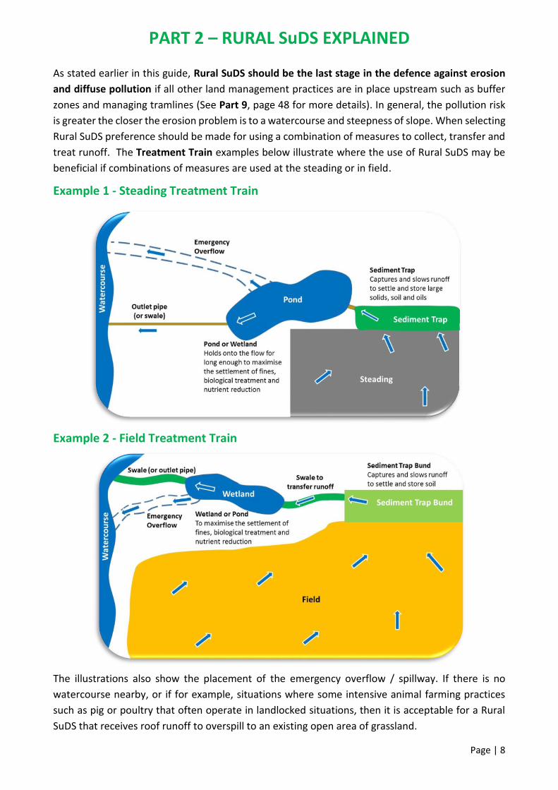
As stated earlier in this guide, Rural SuDS should be the last stage in the defence against erosion
and diffuse pollution if all other land management practices are in place upstream such as buffer
zones and managing tramlines (See Part 9, page 48 for more details). In general, the pollution risk
is greater the closer the erosion problem is to a watercourse and steepness of slope. When selecting
Rural SuDS preference should be made for using a combination of measures to collect, transfer and
treat runoff. The Treatment Train examples below illustrate where the use of Rural SuDS may be
beneficial if combinations of measures are used at the steading or in field.
Example 1 - Steading Treatment Train
Example 2 - Field Treatment Train
The illustrations also show the placement of the emergency overflow / spillway. If there is no
watercourse nearby, or if for example, situations where some intensive animal farming practices
such as pig or poultry that often operate in landlocked situations, then it is acceptable for a Rural
SuDS that receives roof runoff to overspill to an existing open area of grassland.

PART 3 – ASSESSMENT SELECTION DESIGN
Page | 9
Rural SuDS – How to Assess, Select and Design Farmers and advisors should follow the steps below to assess, select and design Rural SuDS.
Farm Environment Assessment and Identification of Issues
1) Carry out a holistic farm assessment of both steading and field areas to identify problem areas
such as field erosion, dirty water running off a yard or roof runoff entering a slurry store.
2) Prepare reports along with steading drainage drawings and field maps highlighting locations of
diffuse pollution. These reports are typically called:
Diffuse Pollution Steading Assessment
Diffuse Pollution Field Assessment
Identification of Solutions
3) Use the Steading Diagram (page 13) and Field Diagram (page 19) to determine sources and
solutions to the problems reported. Note, it may not always be a Rural SuDS that is the best
course of action (See Part 9 - Other Management Options).
Selection of Rural SuDS
4) Use the Steading (Part 4, pages 14-15) and Field (Part 5, page 20) Selection Charts to determine
the Rural SuDS best suited to the diffuse pollution issue on your farm.
Design and build of Rural SuDS
5) Use the Sizing Criteria provided in this guide (pages 16-17 for steading and page 21 for field) to
determine the volume of runoff to be captured in each Rural SuDS.
6) Use the Specification sheets and example drawings provided in Part 7 of this guide to help you
design and build your Rural SuDS.
Note if you are applying for AECS grant funding some Rural SuDS combinations are compulsory
such as a pond or wetland must be combined with a sediment trap. A pond must have a perimeter
stock fence. For other current Agri-Environment Climate Scheme (AECS) eligible funding
requirements, please see the Scottish Government Rural Payments and Services Website

PART 4 – STEADING
Page | 10
Where to use Rural SuDS at the Steading Steadings can present a wide range of pollution risks to the water environment that will vary
depending on farm use such as arable, livestock or mixed, rainfall and the health or sensitivity of the
receiving watercourse. Runoff can range from relatively clean roof water to lightly contaminated
runoff to highly polluting slurry.
It is accepted that clean and general yards will build up some contamination over time from passing
machinery and occasional livestock movements. In the majority of cases this runoff will be suitable
for treatment via a Rural SuDS or alternatively could discharge to an existing local grassed area if
available.
The images below provide some examples of steading areas that can be drained into a Rural SuDS
and steading areas that must be collected and stored and therefore not suitable for Rural SuDS.
Allowed Not Allowed
Roof runoff Livestock standing yards
Clean yard runoff Yards with regular livestock access
Imag
e ©
Ste
war
t M
oir
Im
age
© S
tew
art
Mo
ir
Imag
e ©
Ste
war
t M
oir
Im
age
© S
tew
art
Mo
ir

PART 4 – STEADING
Page | 11
Allowed Not Allowed
General yard runoff Dairy and parlour washings
Outdoor FYM midden runoff (CFW only) Outdoor feeding area runoff
Outdoor silage clamp winter runoff
(CFW only) Silage effluent
Imag
e ©
Ste
war
t M
oir
Imag
e ©
Ste
war
t M
oir
Imag
e ©
Ste
war
t M
oir
Imag
e ©
Ste
war
t M
oir
Imag
e ©
Ste
war
t M
oir
Im
age
© S
tew
art
Mo
ir

PART 4 – STEADING
Page | 12
Steading - Selection Table
It is important to recognise that different Rural SuDS measures should be used to collect and treat
different types of runoff. The table below shows when and where Rural SuDS measures can be used
within a steading storage and management hierarchy to prevent pollution incidents.
Source of Pollution Definition Rural SuDS Option?
Rural SuDS Measures or other Management Options
Runoff from roofs [1] Relatively clean water with a low level of pollution
Swale Sediment Trap Pond Wetland Soakaway Rainwater Harvesting
Runoff from roofs [1] on intensive pig and poultry units
Runoff with a low to moderate level of pollution primarily caused by dust
Swale Sediment Trap Pond / Wetland (if there is space and only when appropriately sited)
Runoff from clean and general yards [1]
Runoff with a low to moderate level of pollution caused by vehicles and occasional livestock movements
Swale Sediment Trap Pond Wetland
Runoff from lightly contaminated areas
Runoff with a higher level of pollution from outdoor FYM middens (all year round) and outdoor silage clamps (winter months only)
Constructed Farm Wetland [2] Effluent Tank
Slurry, Manures and Effluents
Slurry Above Ground Ring / Lagoon / Underground Tank
Dairy & parlour washings Slurry storage
Silage effluent (summer months) Effluent Tank
Sheep dip effluent Application to land [3]
Chemical sprayer runoff Biobeds and biofilters
Veg & fruit processing wastewater Bespoke treatment facilities
(1) It is a statutory requirement that all farm buildings and yards constructed since 1st April 2007 have appropriately
designed sustainable drainage systems installed.
(2) Constructed Farm Wetlands (CFW’s) can be used for runoff from all areas as well as unroofed FYM middens and
silage clamps (winter months only). Roofed structures must drain to an effluent tank at all times.
(3) Subject to land assessment and SEPA authorisation.
High risk sources of pollution (in red above) are not suitable for Rural SuDS and should be managed
by other measures in accordance with existing guidance and legislation. See Farming & Water
Scotland, General Binding Rules 10, 11, 18-24, PEPFAA Code, 4 Point Plan, Farm Soils Plan, SSAFO
Regulations, PPC (Scotland) Regulations.

PART 4 – STEADING
Page | 13
Steading Diagram - Sources of Pollution and Management Solutions Use this diagram to identify best practice for steading waste, effluent and runoff problems.

PART 4 – STEADING
Page | 14
Steading - Selection Chart A Use this chart to determine the suitability of Rural SuDS.

PART 4 – STEADING
Page | 15
Steading - Selection Chart B Use this chart to determine the Rural SuDS best suited for the type of runoff.

PART 4 – STEADING
Page | 16
Steading - Sizing Criteria
Important Note: If you wish to collect and treat runoff from an outdoor FYM midden or outdoor
silage clamp please refer to the CFW Design Manual for guidance on how to size a Constructed
Farm Wetland.
How do I calculate the Treatment Volume for runoff draining to my Rural SuDS?
Treatment Volume (Vt) is the amount of runoff draining from the yard that needs to be cleaned
(or treated) during a design rainfall event.
1. Complete your Steading Drainage Assessment and identify the area(s) suitable for draining to
Rural SuDS.
2. Calculate the surface area(s) to be drained. You should at this stage decide if different areas are
to be treated separately or if they are to be combined.
3. Establish the rainfall value for your location (see What is my Rainfall Value? map, page 17).
4. Determine the Treatment Volume for each surface area using the following design equation.
Steading Design Equation Area Drained (A) x Rainfall (R) = Treatment Volume (Vt)
Where:
(A) = Area Drained is measured in square metres (m2) and is obtained from your Steading Drainage
Assessment.
(R) = Rainfall Depth is measured in metres (m) and is obtained from your location within Scotland
(see the What is my Rainfall Value? map, page 17).
(Vt) = The calculated Treatment Volume (Vt) is measured in cubic metres (m3) and determines the
size of your Rural SuDS
If you have two or more Rural SuDS draining different areas of your steading then calculate the
Vt for each Rural SuDS.
If you have doubt about any aspect of Rural SuDS design seek specialist advice.

PART 4 – STEADING
Page | 17
What is my Rainfall Value?
Farms in Area A have a rainfall value of 0.02 m (20 mm) Farms in Area B have a rainfall value of 0.015 m (15 mm) NOTE: These values are approximations only. Data more specific to your location may be available from your local agricultural consultant.
Average annual rainfall for Scotland. Adapted from CIRIA C753 The SuDS Manual.
How do I know what size and volume my Rural SuDS should be?
Different Rural SuDS measures require different multiples of treatment volume to be stored.
The minimum volume to be stored by each Rural SuDS is:
A Swale or Sediment Trap should hold 1 x Treatment Volume
A Wetland should hold 3 x Treatment Volume
A Pond should hold 4 x Treatment Volume
Worked Example 1:
The general yard area to be drained is 1,500 m2. The farm is located in Ayrshire with a rainfall
value of 0.02 m. The calculated Treatment Volume (1Vt) is 30 m3 (1,500 m2 x 0.02 m). The Rural
SuDS chosen based on the pollution risk from the general yard and sensitivity of the local burn is
a Pond that should be 4 x Treatment Volume (4Vt). The Pond should be designed to hold a
minimum volume of 120 m3 (30 m3 x 4Vt). To receive AECS funding, you must apply the treatment
train approach so the pond must have a sediment trap upstream. A sediment trap Treatment
Volume is 1Vt, therefore the Sediment Trap volume is 30 m3.
Now refer to Part 6 General Design Guidance and Part 7 Specification Sheets to design the shape
and size of your Rural SuDS.

PART 5 – FIELD
Page | 18
Where to use Rural SuDS in the Field Fields can present a wide range of pollution risks to the water environment that will vary depending
on farm use, soil type, field slope, rainfall and health or sensitivity of the receiving watercourse. In
fields, Rural SuDS should be the last option. Best Management Practices (BMP) such as riparian
buffer strips, properly located feed sites and good practice spreading of slurry should always be
implemented first. Farmers and landowners should ensure that they comply with General Binding
Rules 18-24 before considering Rural SUDS.
The images below provide some examples of field issues that can be directed through a Rural SuDS
and those issues that should be solved by other management options.
Rural SuDS may be used Use Other Management Options
Runoff from arable fields Overland runoff from grass fields
Runoff from farm tracks and gateways Runoff from poorly sited feed sites
Runoff onto rural public roads Erosion of watercourse banks
Imag
e ©
Alis
on
Du
ffy
Im
age
© S
tew
art
Mo
ir
Imag
e ©
Alis
on
Du
ffy
Imag
e ©
Ste
war
t M
oir
Imag
e ©
Ste
war
t M
oir
Imag
e ©
Ste
war
t M
oir

PART 5 – FIELD
Page | 19
Field Diagram - Sources of Pollution and Management Solutions Use this diagram to identify best practice for field runoff problems.

PART 5 – FIELD
Page | 20
Field Selection Chart Use this selection chart to determine the Rural SuDS best suited for the type of field runoff.
PART 5 – FIELD
Page | 21
Field Sizing Criteria
Sizing for field Rural SuDS differs from steading areas. They should be sized according to the
following guidelines based on experience gained to date in Scotland and the UK. Please refer to the
design tables in the relevant Rural SuDS specification sheets in Part 7 of this guide for more detailed
information and specific dimensions such as length, width, depth and side slopes.
Field runoff must be captured in a Sediment Trap Bund as a minimum. Where additional treatment
is required, then a swale or pipe should be used to transfer runoff from a sediment trap bund into
a pond or wetland. Ponds and Wetlands are recommended to capture and treat very high nutrient
loads. It is also recommended that if you have doubt about any design aspect of in-field Ponds and
Wetlands then you should seek specialist advice.
Each field measure has a separate design equation as listed below.
Sediment Trap Bund Design Equation
Base Area of a Sediment Trap Bund = 0.25% of field area
Wetland Design Equation
Total Wet Area of a Wetland = minimum 0.50% of field area
Pond Design Equation
Total Wet Area of a Pond = minimum 0.25% of field area
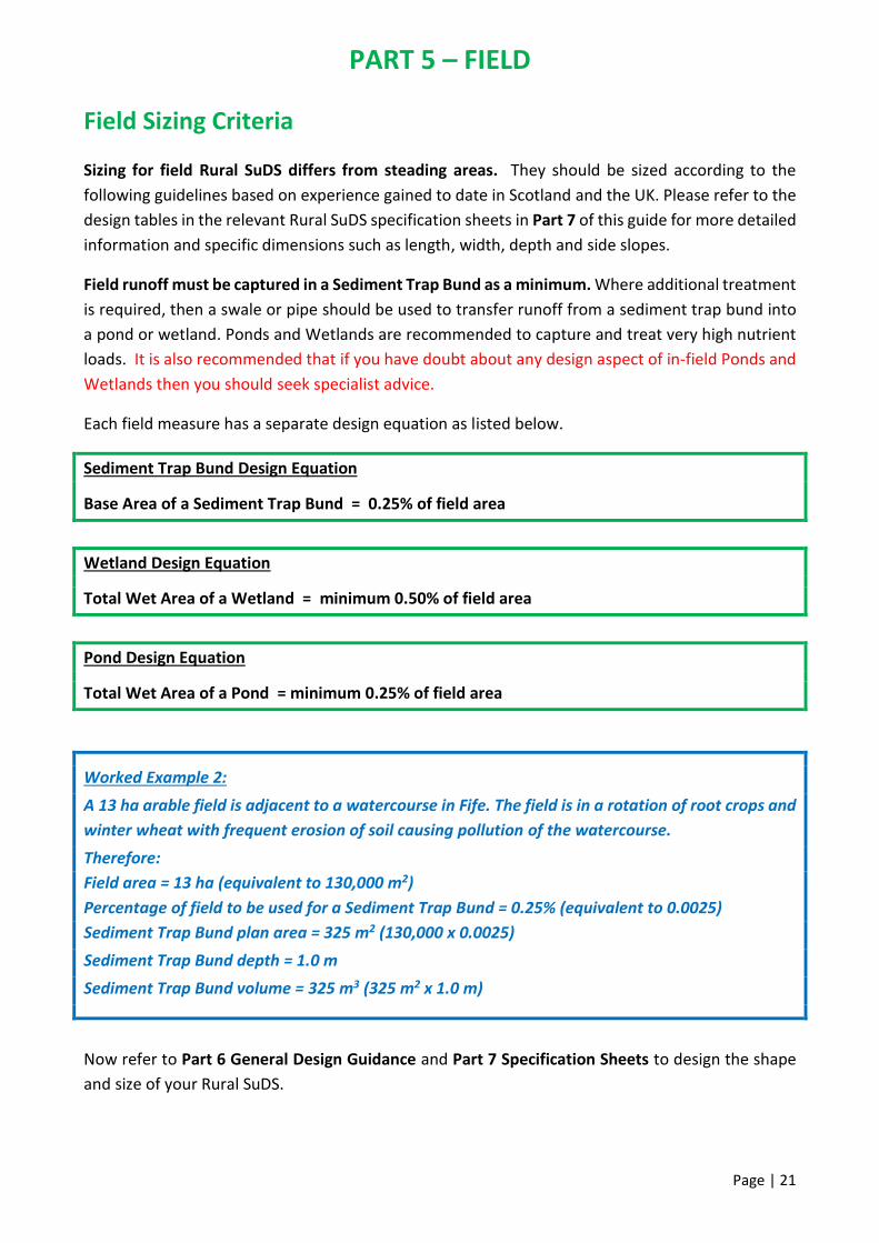
Worked Example 2:
A 13 ha arable field is adjacent to a watercourse in Fife. The field is in a rotation of root crops and
winter wheat with frequent erosion of soil causing pollution of the watercourse.
Therefore:
Field area = 13 ha (equivalent to 130,000 m2)
Percentage of field to be used for a Sediment Trap Bund = 0.25% (equivalent to 0.0025)
Sediment Trap Bund plan area = 325 m2 (130,000 x 0.0025)
Sediment Trap Bund depth = 1.0 m
Sediment Trap Bund volume = 325 m3 (325 m2 x 1.0 m)
Now refer to Part 6 General Design Guidance and Part 7 Specification Sheets to design the shape
and size of your Rural SuDS.

PART 6 – GENERAL DESIGN GUIDANCE
Page | 22
Collection and Transfer of Runoff
For current Agri-Environment Climate Scheme (AECS) eligible funding requirements, please see
the Scottish Government Rural Payments and Services Website.
The design guidance below contains important principles for the construction of all Rural SuDS
whether you wish to apply for an AECS grant or not.
1. If there is insufficient area at the edge of the steading to transfer runoff into a swale, to a
sediment trap, pond or wetland then pipes and manholes can be used. Silt trap manholes should
be used in the pipe routes to trap sediment close to
the source of the pollution.
Note 1. Pipes and silt trap manholes require regular
sediment removal to remain effective.
Note 2. Silt trap manholes have a sump beneath the
outlet pipe to catch sediments. Whilst silt trap
manholes are reasonably effective they do not
provide the same level of treatment as a swale or a
sediment trap.
Note 3. Silt trap manholes cannot be funded through AECS.
2. Piped inlets and outlets are detailed in this guidance with large stones under the pipe. This slows
and reduces runoff energy at the inlet and limits erosion on the base of the Rural SuDS. The
stones also prevent re-suspension of settled sediments. Stones at the outlet also reduce plant
overgrowth that can cause blockage and limit visibility for inspections.
3. Diameter of pipes used for inlets and outlets are a function of area and rainfall. They should be
sized in accordance with the tables provided below.
INLET PIPES OUTLET PIPES
Area Drained (m2) Pipe Diameter (mm) Pipe Diameter (mm) Pipe Gradient Discharge Rate (litres/second)
Up to 400 100 100 1 in 150 5
500 150 100 1 in 100 6
1,000 150 100 1 in 60 8
2,000 225 150 1 in 150 15
3,000 225 150 1 in 100 18
4,000 300 150 1 in 60 23
5,000 300 Note 1 Inlet and outlet pipes should be plastic pipes with a smooth inner wall.
Note 2 Inlet pipes should be laid no shallower than 1 in 100 fall.
Note 3 Outlet pipes should never be laid shallower than 1 in 150 fall.
Imag
e ©
Ste
war
t M
oir

PART 6 – GENERAL DESIGN GUIDANCE
Page | 23
4. Situations where Rural SuDS should be surrounded by a fence include:
To protect people and the structure from livestock poaching or vehicle over-run.
To protect livestock from the risk of diseases such as Liver-fluke and
Cryptosporidium.
5. Grass buffer strips should be used prior to all field Rural SuDS to slow the flow and remove a
proportion of coarse solids prior to entering the structure.
6. Emergency overflows or spillways should be included in the design of all Rural SuDS to manage
exceedance flows. Emergency overflows prevent overtopping during extreme rainfall events
that can cause embankment erosion and prevent outlet failure (See page 8 for more information
about emergency overflows).
Landscaping, Habitat and Biodiversity Enhancement
7. When implementing Rural SuDS Ponds or Wetlands,
these should be new structures and not existing
wildlife ponds or natural wetlands. This is because
existing habitats (plants and wildlife) could be
damaged if used to treat potentially polluted water
from a steading or field. Whilst Rural SuDS are
designed to mimic natural processes and may create
habitats, they are primarily designed for the
treatment of rainfall or lightly contaminated runoff.
8. Ways that you can maximise biodiversity potential of your Rural SuDS are provided below. This
information including more useful tips can be found in WWT Constructed Farm Wetlands Guide
and Part 3 of the RSPB / WWT Sustainable Drainage Systems Guide.
Excavated top soil can be used to create variation in topography to increase habitat diversity
and wildlife potential in swales, ponds and wetlands.
Encourage digger operators to leave rough bank profiles rather than over-perfecting.
Permeable check dams in swales using stones to slow, but not impede flow provides shallow
pools that benefit wildlife while increasing sedimentation and infiltration. You could replace
stones with woody debris or willow hurdles to enhance natural aesthetics.
Where possible, allow natural colonisation of plants.
Avoid cutting vegetation between spring to late July-August, to provide habitat for
pollinators (birds / insects etc.) and cover for breeding wildlife.
Gentle slopes ensure valuable wildlife habitat, as well as acting as a safety feature.
Imag
e ©
Alis
on
Du
ffy

PART 6 – GENERAL DESIGN GUIDANCE
Page | 24
9. All Rural SuDS should be planted with native species. See the table below for examples of
suitable planting schemes.
Rural SuDS Location Plant Species
Swales and
Sediment Traps
Base and
side slopes
Hardy, low maintenance grass seed mix
For example 70% creeping red fescue, 20%
smooth-stalked meadow grass and 10%
creeping bent
Ponds and
Wetlands
Margins Bulrush (Typha latifolia) *
Common Reed (Phragmites australis) *
Yellow Flag Iris (Iris pseudacorus)
Branched Bur-reed (Sparganium erectum) *
Greater Pond Sedge (Carex riparia) *
Lesser Pond Sedge (Carex acutiformis)
Vegetated marsh Yellow Flag Iris (Iris pseudacorus)
Reed Sweet-grass (Glyceria maxima)
Reed Canary-grass (Phalaris arundinacea)
Lesser Pond Sedge (Carex acutiformis)
Marsh Marigold (Caltha palustris)
Marsh Woundwort (Stachys palustris)
Rushes (Juncus spp.)
Side slopes Wildflower, low maintenance grass seed mix
Note 1 * Vigorous species that will form dominant stands – do not mix vigorous plant species.
Note 2 Plants should be sourced from nursery stock and not gathered from the wild.
The following Specification Sheets provide information to assist you to design and build Rural
SuDS. Details include an overview of function, construction specifications, and example
drawings. Basic maintenance activities are also provided.
If you have doubt about any aspect of Rural SuDS design, please seek specialist advice.

PART 7 – SPECIFICATION SHEET SWALE
Page | 25
SWALE
What is a Swale?
A swale is a linear, dry, grass channel laid with a shallow fall on its base. Swales are designed to
collect and transfer runoff during rainfall events. Swales are dry channels and water is only normally
found in them following rainfall. Swales are cheaper to construct than piped systems.
What does a Swale do?
At the steading a swale captures rainfall runoff from roofs, yards and areas draining onto yards.
They attenuate runoff and slow down the rate that runoff reaches a downstream grass strip (if
appropriate), Rural SuDS or watercourse. The grass surface of a swale helps to filter coarse
sediments and pollutants in runoff allowing them to settle out and be retained within the swale. On
permeable sandy and loamy soils runoff will also infiltrate into the soil below the base of the swale.
In fields swales are used as above ground pipes to transfer runoff between two Rural SuDS or from
a Rural SuDS at the end of a treatment train to a burn, river, loch or the sea.
What can I use a Swale for?
Collect and attenuate steading runoff from clean roofs, before discharge to a watercourse.
Collect and attenuate steading runoff from roofs on pig and poultry farms and / or transfer into
a pond or wetland for further treatment.
Collect, attenuate and transfer steading runoff from clean and general yards into a sediment
trap, pond or wetland for further treatment.
A lined swale can collect, attenuate and transfer steading runoff from lightly contaminated areas
into a Constructed Farm Wetland (CFW).
Transfer runoff in fields between sediment trap bunds, ponds and wetlands.
What does a Swale look like?
Sheet flow off a yard into a swale Swale on a slope with stone check-dams
Useful Tip: Use stone check dams to slow down runoff in swales on steeper slopes.
Imag
e ©
Ste
war
t M
oir
Imag
e ©
Far
min
g an
d W
ate
r Sc
otl
and

PART 7 – SPECIFICATION SHEET SWALE
Page | 26
What makes a good Swale?
Swales work best when runoff flows directly off the yard surface (sheet flow) and down the
swale side slope into the base; swales can also receive runoff in pipes from roofs or yards.
The longer the better, a long swale gives more time for filtration and settlement of sediments.
A swale should have no sharp bends; swales should curve gently around buildings and yards.
Swale base gradients should be shallow and no greater than 5 degrees (1 in 20). Swales can be
built on steeper ground if designed to slow flow and reduce the risk of erosion.
Suitable measures for steep sites include stepped swales, following contours so that the swale
curves to and fro across the slope to achieve a shallower gradient, or use of check-dams.
Best Practice Construction Guidance for a Swale
Divert runoff during construction and establishment phases until a grass sward is established on
the base and side slopes.
Finish construction by the end of the growing season to promote a healthy grass sward.
Stockpile the stripped topsoil nearby for use later. Make sure that the topsoil is not washed into
the structure during construction.
Excavate and form base and side slopes as required.
Install pipes and erosion protection areas where required.
Replace the stripped topsoil over the base and side slopes at a maximum depth of 150 mm (6
inches). The placement must be done when the topsoil is dry to avoid compaction.
If the slope is steep, form stone check dams at regular intervals along the swale base. Check
dams should be at least 10 m (30 feet) apart.
Sow an appropriate hardy, low amenity, low maintenance grass seed mixture (see part 6 General
Design Guidance, page 24 for details) that can withstand sediment loading over the topsoil to
establish a healthy grass sward. Sow at 25 g/m2 (grams per square metre).
If required, fencing should be erected at least 600 mm (2 feet) off the top edge of side slopes.
Best Practice Maintenance for a Swale
A long grass sward should be maintained on a swale base at all times (max 100 mm) as this
encourages sediments to settle out. This is achieved by regular cutting (in the growing season).
Inlet / outlet pipes should be checked for blockages, vegetation build-up and debris (at least
twice per year and following heavy rainfall) and cleared as necessary.
If in place, perimeter fencing should be checked for integrity / holes and repaired as required.
Significant accumulated sediment and debris on the base of a swale to be removed as required
– a sign will be ponding on the swale base e.g. if water remains in sections of the swale following
rainfall. As a rule of thumb, if sediment levels are above the bottom of the inlet or outlet pipe
then you should remove the accumulated sediment.
Repair eroded or damaged areas of grass as required to restore design performance.
If Rural SUDS are not maintained in accordance with the above basic guidelines, they will no
longer treat runoff and may release their pollutants to the watercourse they are protecting.

PART 7 – SPECIFICATION SHEET SWALE
Page | 27
Recommended Specifications and Example Drawings for a Swale
The table below provides recommended minimum and maximum dimensions for a swale. This will
help you choose the most suitable swale for your steading. The table should be read in conjunction
with the example drawings that show the general layout of a swale and how it should be
constructed. The actual dimensions of a swale will depend on its location, the natural fall of the
ground, how runoff enters the structure (across the surface as sheet flow or from a pipe), and the
volume of runoff to be collected.
Description of Feature Minimum Maximum
(millimetres) (feet) (millimetres) (feet)
Grass Strip Width 600 2 1,200 4
Base Width 600 2 2,000 6½
Depth 300 1 1,000 3½
Top Width 2,400 8 varies according to base width and depth
Side Slope 1 in 3 * 1 in 4
Topsoil Depth 150 mm (6 inches)
Base Fall (optimum) 1 in 200 to 1 in 300 (3 to 5 mm fall every 1 m)
Base Fall (maximum) 1 in 100 (10 mm fall every 1 m)
* Note: Steeper side slopes may be used in swales that receive only pipe flow or where space is limited. Side slopes
should never be steeper than 1 in 2. It is feasible where space is limited to design a sheet flow swale with the far slope
(away from a path or steading) with a 1 in 2 gradient.
Swale: Typical Plan

PART 7 – SPECIFICATION SHEET SWALE
Page | 28
Swal
e:
Typ
ical
Inle
t C
ross
-Sec
tio
n (
Pip
e Fl
ow
)
N
ote
: Th
e in
tern
al d
iam
eter
of
the
inle
t p
ipe
sho
uld
be
des
ign
ed f
or
the
are
a d
rain
ed
(se
e p
ag
e 2
2)
Sw
ale
: Ty
pic
al O
utl
et C
ross
-Sec
tio
n
N
ote
: Th
e o
utl
et p
ipe
mu
st b
e a
min
imu
m o
f
10
0 m
m (
4 in
ches
) in
tern
al d
iam
eter
Sw
ale
: C
hec
k D
am L
on
g-Se
ctio
n
Swal
e:
Typ
ical
Cro
ss-S
ecti
on
No
te:
Swa
les
use
d t
o c
on
vey
ligh
tly
con
tam
ina
ted
ru
no
ff f
rom
a s
ilag
e cl
am
p o
r
FYM
mid
den
in
to a
Co
nst
ruct
ed F
arm
Wet
lan
d m
ust
ha
ve a
wa
terp
roo
f lin
er
inst
alle
d b
etw
een
th
e su
bso
il a
nd
to
pso
il la
yers
to
pre
ven
t in
filt
rati
on
of
the
ligh
tly
con
tam
inat
ed
ru
no
ff in
to t
he
soil.
Swal
e:
Ch
eck
Dam
Cro
ss-S
ecti
on

PART 7 – SPECIFICATION SHEET SEDIMENT TRAP
Page | 29
SEDIMENT TRAP
What is a Sediment Trap?
A sediment trap is a dry, shallow, grass basin laid with a shallow fall on its base. Sediment traps
collect, retain and treat runoff during rainfall events. Sediment traps are dry structures that
temporarily fill with water after rainfall events.
What does a Sediment Trap do?
A sediment trap captures rainfall runoff from roofs, yards and areas draining onto yards. Sediment
traps attenuate runoff and slow down the rate that it reaches the local watercourse. The grass
surface of the trap helps to filter sediments and pollutants (such as grit, sand, soil and oils) within
runoff retaining them within the trap. On permeable sandy and loamy soils runoff will also infiltrate
into the soil below the base of the sediment trap. Whilst a sediment trap in this guide is designed
for treating rainfall runoff they will always provide some flood storage. Their use in flood
management scenarios should be considered at the design stage and sized appropriately.
What can I use a Sediment Trap for?
Collect and attenuate steading runoff from clean roofs before discharge to a watercourse.
Collect, attenuate and transfer steading runoff from clean and general yards into a pond or
wetland for further treatment.
To collect, attenuate and treat steading runoff from roofs (and yards) on pig and poultry units if
site conditions are suitable
What does a Sediment Trap look like?
A newly constructed sediment trap with established grass on the base and side slopes Note: surrounds have yet to be grassed over
Pipe flow discharging across loose stone to reduce the energy of the flow and manage
erosion of the inlet area
Imag
e ©
Ste
war
t M
oir
Imag
e ©
Ste
war
t M
oir

PART 7 – SPECIFICATION SHEET SEDIMENT TRAP
Page | 30
What makes a good Sediment Trap?
The larger the surface area of a sediment trap the better; large surface areas gives more time
for the filtration and settlement of sediments.
Sediment traps work best if runoff can flow directly off the yard surface (sheet flow) and down
the side slope of the sediment trap into the base. If sheet flow is not feasible, they can also
receive runoff via pipes.
Best Practice Construction Guidance for a Sediment Trap
Divert runoff during construction and establishment phases until a grass sward is established on
the base and side slopes.
Construct during the growing season to promote establishment of a healthy grass sward.
Stockpile the stripped topsoil nearby for use later. Make sure that the topsoil is not washed into
the structure during construction.
Excavate and form base and side slopes as required.
Install pipes and erosion protection areas where required.
Replace the stripped topsoil over the base and side slopes at a maximum depth of 150 mm (6
inches). The placement must be done when the topsoil is dry to avoid compaction.
Where slopes are steep, construct sediment trap basins in series linking them by pipes, swales
or a cut away in the bank between each basin.
Sow an appropriate low amenity, low maintenance grass seed mixture that can withstand
sediment loading over the topsoil to establish a grass sward. Sow at 25 g/m2 (grams per square
metre).
A sediment trap should have a shallow fall across the length of the base. Gradients should be
shallow and no greater than 5 degrees (1 in 20). Sediment traps can be built on steeper ground
if they are stepped in series.
If required, perimeter livestock fencing should be erected at least 600 mm (2 feet) off the top
edge of all side slopes.
Best Practice Maintenance for a Sediment Trap
A long grass sward should be maintained on a sediment trap base at all times (max 100 mm).
This is best facilitated by regular strimming or mowing (at least twice per growing season).
Inlet and outlet pipes should be checked for blockages, vegetation build-up and debris (at least
twice per year and following heavy rainfall) and cleared as necessary.
If in place, perimeter fencing should be checked for integrity / holes and repaired as required.
Significant accumulated sediment and debris on the base of a sediment trap to be removed as
required – a sign will be ponding on the base e.g. if water remains in sections following rainfall.
As a rule of thumb, if sediment levels are above the bottom of the inlet or outlet pipe then you
should remove the accumulated sediment to restore design performance.
Repair eroded or damaged areas of grass as required to restore design performance.
If Rural SUDS are not maintained in accordance with the above basic guidelines, they will no
longer treat runoff and may release their pollutants to the watercourse they are protecting.

PART 7 – SPECIFICATION SHEET SEDIMENT TRAP
Page | 31
Recommended Specifications and Example Drawings for a Sediment Trap
The table below provides recommended minimum and maximum dimensions for a sediment trap.
The range of dimensions will help you choose the most suitable sediment trap for your steading.
The table should be read in conjunction with the example drawings that show the general layout of
a sediment trap and how it should be constructed. The actual dimensions of a sediment trap will
depend on its location, the natural fall of the ground, how runoff enters the structure (across the
surface as sheet flow or from a pipe), and the volume of runoff to be stored.
Description of Feature Minimum Maximum
(millimetres) (feet) (millimetres) (feet)
Grass Strip Width * 600 2 1,200 4
Base Width 3,000 10 10,000 30
Base Length 10,000 30 30,000 100
Depth 600 2 1,000 3½
Top Width 6,600 22 varies according to base length & depth
Side Slope 1 in 3 ** 1 in 4
Topsoil Depth 150 mm (6 inches)
Base Length Fall 1 in 100 to 1 in 300 (3 to 10 mm fall every 1 m)
* Note: Grass strips are only required where runoff enters the sediment trap as sheet flow.
** Note: Steeper side slopes may be used in sediment traps that receive only pipe flow or where space on site is
limited; side slopes should never be steeper than 1 in 2.
Sediment Trap: Typical Plan

PART 7 – SPECIFICATION SHEET SEDIMENT TRAP
Page | 32
Sed
imen
t Tr
ap: T
ypic
al C
ross
-Sec
tio
n
Sed
imen
t Tr
ap: T
ypic
al In
let
Cro
ss-S
ecti
on
(P
ipe
Flo
w)
No
te:
The
inte
rna
l dia
met
er o
f th
e in
let
pip
e sh
ou
ld b
e
des
ign
ed f
or
the
are
a d
rain
ed
(se
e p
ag
e 2
2)
Sed
imen
t Tr
ap: T
ypic
al O
utl
et C
ross
-Sec
tio
n
No
te:
The
ou
tlet
pip
e m
ust
be
a m
inim
um
of
10
0 m
m (
4 in
ches
) in
tern
al d
iam
eter

PART 7 – SPECIFICATION SHEET POND
Page | 33
POND
What is a Pond?
A pond is a permanent water basin with shallow planted margins. Ponds are designed to collect,
retain and treat runoff during rainfall events.
What does a Pond do?
A pond captures rainfall runoff from roofs, yards and areas draining onto yards or constructed as
part of a Rural SuDS treatment train in fields. Ponds attenuate runoff and slow down the rate that
runoff reaches the local watercourse. The forebay at the inlet of a pond allows sediments and
pollutants to settle out and be retained. The permanent pool of water and planted margins facilitate
further treatment by a range of natural processes including sedimentation, biological breakdown
and nutrient uptake. They can also help in flood risk management situations if sized appropriately.
What can I use a Pond for?
To collect, attenuate and treat steading runoff from roofs, clean and general yards
To collect, attenuate and treat steading runoff from roofs (and yards) on pig and poultry units if
site conditions are suitable and if combined with a swale or sediment trap
For enhanced treatment (if required) of field runoff downstream of a sediment trap bund
What does a Pond look like?
A new pond for a farm steading. A well established pond with
planted margins after 2 years.
Useful Tip: Plant the topsoil margins prior to filling up the pond with water.
Imag
e ©
Ste
war
t M
oir
Imag
e ©
Ste
war
t M
oir

PART 7 – SPECIFICATION SHEET POND
Page | 34
What makes a good Pond?
A sediment trap upstream of a pond as part of the Rural SuDS treatment train is an AECS
requirement. The sediment trap extends the operational life of the pond and will reduce the
frequency of maintenance tasks such as sediment removal.
The permanent pool should be 1.2 m – 2.00 m deep as this prevents encroachment of plants.
Ponds should have planted margins as they provide additional treatment for nutrients and
habitat benefits as well as a safety barrier around the body of water.
Best Practice Construction Guidance for a Pond
Divert runoff during construction and establishment phases until such time that topsoil has been
placed on perimeter margins.
Ponds should be constructed during the growing season to promote establishment of marginal
aquatic plants and grass on side slopes.
Stockpile the stripped topsoil nearby for use later. Make sure that the topsoil is not washed into
the structure during construction.
Excavate and form base, forebay and berm, aquatic margins and side slopes as required.
On sandy soils lay 300 mm (12 inches) of clay or a plastic impermeable membrane (minimum 1
mm thick) up to the underside of the outlet pipe to ensure the pond retains water.
The forebay base area should be approximately 20% of the pond base area with a minimum
length of 2.00 m (6.5 feet). The berm should extend across the entire width of the Pond.
Install inlet / outlet pipes and erosion protection areas.
Inlet pipe(s) should be placed as far away as possible from the outlet. This reduces the potential
of flows to short circuit by maximising flow detention times e.g. increases the time flow takes to
reach the outlet allowing sediments and associated pollutants to settle.
Replace stripped topsoil at a maximum depth of 300 mm (12 inches) on aquatic margins and 150
mm (6 inches) over the side slopes. Do this when the topsoil is dry to avoid compaction.
Plant appropriate aquatic marginal plants in the topsoil margin. Planting density to be 4 plants
/ m2 (per square metre).
Sow a low amenity, low maintenance grass seed mixture that can withstand sediment loading
over the topsoil to establish a grass sward. Sow at 25 g/m2 (grams per square metre).
If required, perimeter livestock fencing should be erected at least 600 mm (2 feet) off the top
edge of all side slopes.
Best Practice Maintenance for a Pond
Inlet and outlet pipes should be checked for blockages, vegetation build-up and debris (at least
twice per year and following heavy rainfall) and cleared as necessary.
Perimeter stock fencing should be checked for integrity / holes and repaired as required.
Significant accumulated sediment at the inlet / outlet pipes to be removed as required.
Repair eroded or damaged areas of grass / plants as required to restore design performance.
If Rural SUDS are not maintained in accordance with the above basic guidelines, they will no
longer treat runoff and may release their pollutants to the watercourse they are protecting.
PART 7 – SPECIFICATION SHEET POND
Page | 35
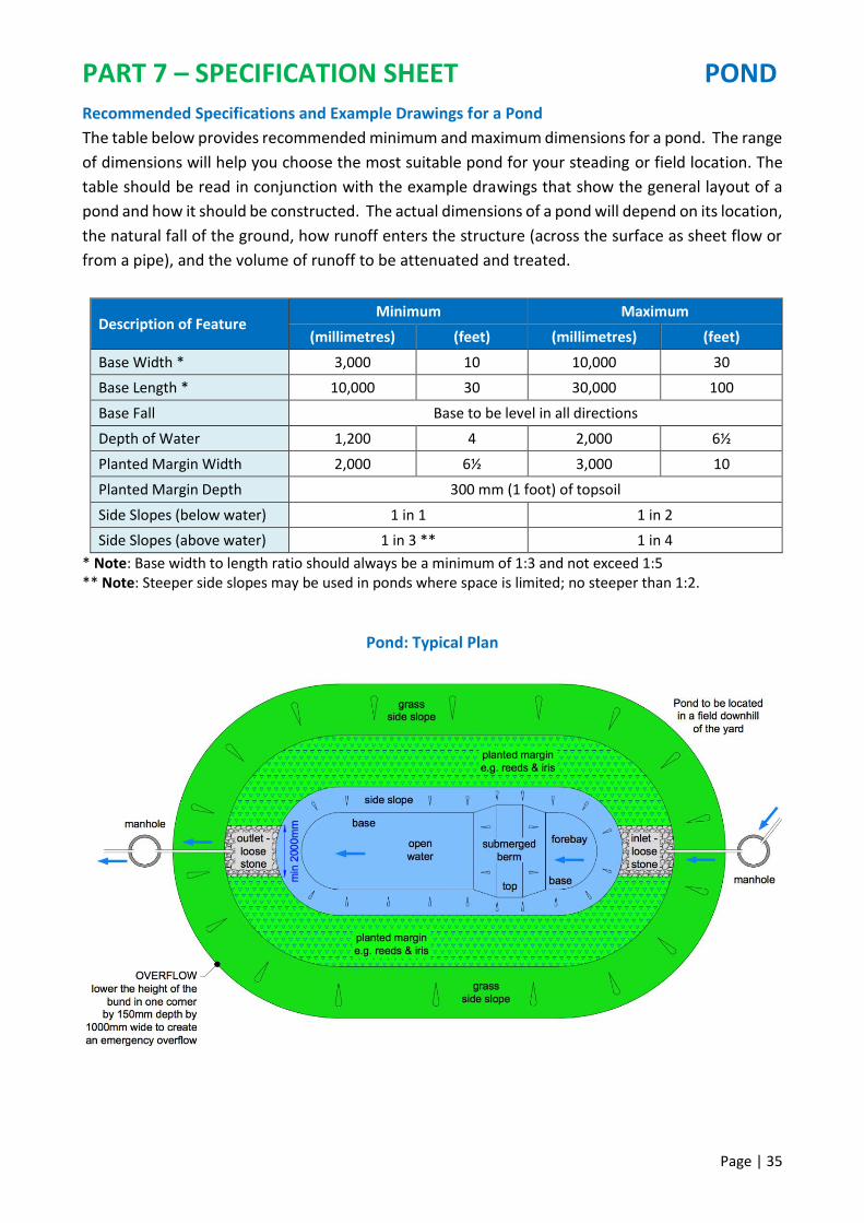
Recommended Specifications and Example Drawings for a Pond
The table below provides recommended minimum and maximum dimensions for a pond. The range
of dimensions will help you choose the most suitable pond for your steading or field location. The
table should be read in conjunction with the example drawings that show the general layout of a
pond and how it should be constructed. The actual dimensions of a pond will depend on its location,
the natural fall of the ground, how runoff enters the structure (across the surface as sheet flow or
from a pipe), and the volume of runoff to be attenuated and treated.
Description of Feature Minimum Maximum
(millimetres) (feet) (millimetres) (feet)
Base Width * 3,000 10 10,000 30
Base Length * 10,000 30 30,000 100
Base Fall Base to be level in all directions
Depth of Water 1,200 4 2,000 6½
Planted Margin Width 2,000 6½ 3,000 10
Planted Margin Depth 300 mm (1 foot) of topsoil
Side Slopes (below water) 1 in 1 1 in 2
Side Slopes (above water) 1 in 3 ** 1 in 4
* Note: Base width to length ratio should always be a minimum of 1:3 and not exceed 1:5 ** Note: Steeper side slopes may be used in ponds where space is limited; no steeper than 1:2.
Pond: Typical Plan

PART 7 – SPECIFICATION SHEET POND
Page | 36
Po
nd
: Typ
ical
Cro
ss-S
ecti
on
No
te:
The
inte
rna
l dia
met
er o
f th
e
inle
t p
ipe
sho
uld
be
des
ign
ed f
or
the
are
a d
rain
ed (
see
pa
ge
22
)
No
te:
The
inle
t p
ipe
can
be
rep
lace
d
wit
h a
sw
ale
; th
e sw
ale
ba
se s
ho
uld
ente
r th
e p
on
d a
t th
e sa
me
hei
gh
t
as
a p
ipe
No
te:
The
ou
tlet
pip
e m
ust
be
a
min
imu
m o
f 1
00
mm
(4
inch
es)
inte
rna
l dia
met
er
Po
nd
: Typ
ical
Inle
t C
ross
-Sec
tio
n
Po
nd
: Typ
ical
Ou
tlet
Cro
ss-S
ecti
on

PART 7 – SPECIFICATION SHEET WETLAND
Page | 37
WETLAND
Wetland Types
There are two types of Rural SuDS wetland: (1) a Wetland for the treatment of rainfall runoff from
roofs and clean / general yards, from fields or from farm tracks; (2) a Constructed Farm Wetland
(CFW) for the treatment of lightly contaminated runoff from an outdoor FYM midden or outdoor
silage clamp as previously stated in this guide. If you wish to build a CFW please refer to the
Scotland and Northern Ireland CFW Design Manual. This specification sheet is for a Wetland.
Note: a CFW can be used to accept combined steading rainfall runoff (clean and lightly
contaminated). The surface area of a CFW can be reduced by using Swales, Sediment Traps, Ponds
and Wetlands for rainfall runoff from roofs, clean yards and general yards.
What is a Wetland?
A wetland is a permanent water structure with at least three distinct zones each with different
depths of water and vegetation density; deeper at the inlet, shallow in the middle and vegetated
marsh at the outlet.
What does a Wetland do?
A wetland treats runoff by attenuating and slowing down the rate of flow before it reaches the
watercourse. The forebay at the inlet allows sediments and pollutants to settle out. The shallow
water and vegetated marsh sections facilitate enhanced treatment by a range of natural processes
including sedimentation, nutrient uptake and biological breakdown of bacteria. They can also help
in flood risk management situations if sized appropriately.
What can I use a Wetland for?
To collect, attenuate and treat steading runoff from roofs, clean and general yards
To collect, attenuate and treat steading runoff from roofs (and yards) on pig and poultry units if
site conditions are suitable and if combined with a swale or sediment trap
For enhanced treatment (if required) of field runoff downstream of a sediment trap bund
What does a Wetland look like?
Forebay (inlet) deep water with planted margins
Vegetated marsh (outlet) very shallow water with a diverse plant habitat
Imag
e ©
Ste
war
t M
oir
Imag
e ©
Ste
war
t M
oir

PART 7 – SPECIFICATION SHEET WETLAND
Page | 38
What makes a good Wetland?
Upstream treatment as part of the Rural SuDS treatment train (e.g. a swale or sediment trap /
bund) can extend the operational life of the wetland. This can reduce future maintenance
requirements.
The forebay pool should be 1.2 m – 2.00 m deep in order to prevent encroachment of plants.
Wetlands should comprise 25% of their surface areas as a forebay, 25% as shallow water and
50% vegetated marsh with very shallow water.
Best Practice Construction Guidance for a Wetland
Divert runoff during construction and establishment phases until such time that topsoil has been
placed on perimeter margins.
Wetlands should be constructed during the growing season to promote establishment of
marginal aquatic plants and a healthy grass sward on the side slopes.
Stockpile the stripped topsoil nearby for use later. Make sure that the topsoil is not washed into
the structure during construction.
Excavate and form base, aquatic margins and side slopes as required.
On sandy soils lay 300 mm (12 inches) of clay or a plastic impermeable membrane (minimum 1
mm thick) up to the underside of the outlet pipe to ensure the pond retains water.
Install inlet / outlet pipes and erosion protection areas.
Inlet pipe(s) should be placed as far away as possible from the outlet. This reduces the potential
of flows to short circuit by maximising flow detention times e.g. increases the time flow takes to
reach the outlet allowing sediments and associated pollutants to settle.
Replace stripped topsoil at a maximum depth of 300 mm (12 inches) on aquatic margins and 150
mm (6 inches) over the side slopes. Do this when the topsoil is dry to avoid compaction.
Plant appropriate aquatic marginal plants in the topsoil margin. Planting density to be 4 plants /
m2 (per square metre).
Sow a low amenity, low maintenance grass seed mixture that can withstand sediment loading
over the topsoil to establish a grass sward. Sow at 25 g/m2 (grams per square metre).
If required, perimeter livestock fencing should be erected at least 600 mm (2 feet) off the top
edge of all side slopes.
Best Practice Maintenance for a Wetland
Inlet and outlet pipes should be checked for blockages, vegetation build-up and debris (at least
twice per year and following heavy rainfall) and cleared as necessary.
If in place, perimeter fencing should be checked for integrity / holes and repaired as required.
Significant accumulated sediment at the inlet / outlet pipes to be removed as required.
Repair eroded or damaged areas of grass / plants as required to restore design performance.
If Rural SUDS are not maintained in accordance with the above basic guidelines, they will no
longer treat runoff and may release their pollutants to the watercourse they are protecting.

PART 7 – SPECIFICATION SHEET WETLAND
Page | 39
Recommended Specifications and Example Drawings for a Wetland
The table below provides recommended minimum and maximum dimensions for a wetland. The
range of dimensions will help you choose the most suitable wetland for your steading or field
location. The table should be read in conjunction with the example drawings that show the general
layout of a wetland and how it should be constructed. The actual dimensions of a wetland will
depend on its location, the natural fall of the ground, how runoff enters the structure (across the
surface as sheet flow or from a pipe), and the volume of runoff to be attenuated and treated.
Description of Feature Minimum Maximum
(millimetres) (feet) (millimetres) (feet)
Base Width * 3,000 10 10,000 30
Base Length * 10,000 30 30,000 100
Base Fall Base to be level in all directions
Depth of Water (forebay) 1,200 4 2,000 6½
Depth of Water (shallow) 450 1½ 750 2½
Depth of Water (marsh) 0 0 100 4 inches
Planted Margin Width 2,000 6½ 3,000 10
Planted Margin Depth 300 mm (1 foot) of topsoil
Side Slopes (below water) 1 in 1 1 in 2
Side Slopes (above water) 1 in 3 ** 1 in 4
* Note: Base width to length ratio should always be a minimum of 1:3 and not exceed 1:5
** Note: Steeper side slopes may be used in wetlands where space is limited; no steeper than 1:2.
Wetland: Typical Plan

PART 7 – SPECIFICATION SHEET WETLAND
Page | 40
Wet
lan
d: T
ypic
al S
ecti
on
of
Fore
bay
(In
let)
N
ote
: W
etla
nd
s m
ust
nev
er b
e u
sed
fo
r lig
htl
y co
nta
min
ate
d r
un
off
fro
m a
n o
utd
oo
r si
lag
e cl
am
p o
r
ou
tdo
or
FY
M m
idd
en.
Thes
e fl
ow
s m
ust
be
dir
ecte
d in
to a
Co
nst
ruct
ed F
arm
Wet
lan
d (
CFW
).
Wet
lan
d: T
ypic
al S
ecti
on
of
Shal
low
Wat
er
(Mid
dle
)

PART 7 – SPECIFICATION SHEET WETLAND
Page | 41
Wet
lan
d: T
ypic
al S
ecti
on
of
Veg
etat
ed
Mar
sh (
Ou
tlet
)
Wet
lan
d: T
ypic
al O
utl
et C
ross
-Sec
tio
n
No
te:
The
ou
tlet
pip
e m
ust
be
a m
inim
um
of
10
0 m
m (
4 in
ches
) in
tern
al d
iam
eter
Wet
lan
d: T
ypic
al In
let
Cro
ss-S
ecti
on
(P
ipe
Flo
w)
No
te:
The
inte
rna
l dia
me
ter
of
the
inle
t p
ipe
sho
uld
be
des
ign
ed f
or
the
are
a d
rain
ed
(se
e p
ag
e 2
2)
No
te:
The
inle
t p
ipe
can
be
rep
lace
d w
ith
a s
wa
le;
the
swa
le b
ase
Sho
uld
en
ter
the
wet
lan
d a
t th
e sa
me
hei
gh
t a
s a
pip
e

PART 7 – SPECIFICATION SHEET SEDIMENT TRAP BUND
Page | 42
SEDIMENT TRAP BUND
What is a Sediment Trap Bund?
A sediment trap bund is an excavated in-field earth berm that intercepts and traps sediment laden
flows and associated pollutants via sheet flow before discharge to a watercourse.
What does a Sediment Trap Bund do?
A sediment trap bund reduces the risk of pollution where the potential for soil erosion poses the
greatest risk to a burn, river or loch. Sediment trap bunds are particularly useful on sloping fields
where runoff tends to exit the field at a specific point e.g. low corners, a gateway or where slopes
converge. On permeable sandy and loamy soils runoff will also infiltrate into the soil below the
base. Whilst a sediment trap bund in this guide is designed for treating rainfall runoff they will
always provide some flood storage. Their use as natural flood management measures should be
considered at the design stage and sized appropriately (for more information see page 46).
What can I use a Sediment Trap Bund for?
To attenuate in-field soil laden flows that currently discharge to a watercourse
× Sediment trap bunds should not be used for the interception of runoff from field drains
× Sediment trap bunds should not be used as a flood embankment
What does a Sediment Trap Bund look like?
Excavation of a sediment trap bund Sediment trap bund in operation
BUND
TRAP
Imag
e ©
Ric
har
d L
ock
ett
Imag
e ©
Ric
har
d L
ock
ett

PART 7 – SPECIFICATION SHEET SEDIMENT TRAP BUND
Page | 43
What makes a good Sediment Trap Bund?
Sediment trap bunds typically receive runoff via sheet flow. The larger the surface area the
better; large surface areas give more time for the filtration and settlement of sediments.
A grass filter strip upstream of the bund is critical to help slow flows and reduce turbulence so
that sediments can quickly settle in the trap thus enhancing treatment effectiveness.
As far as possible use the natural topography to reduce excavation or embankments.
Ensure easy access for removal of sediments and nutrients that can be returned to the land.
Best Practice Construction Guidance for a Sediment Trap Bund
Install overflow pipes to control maximum water level.
Infield operations should only be undertaken during dry weather.
Strip the topsoil and stockpile it nearby for use later; the stockpile of topsoil should be located
so that the topsoil is not washed into the new sediment trap bund during the construction works.
Excavate and form the sediment trap bund base and side slopes as required.
Install pipes where required.
Spread the stripped topsoil over the bund as required. The placement must be done when the
topsoil is dry to avoid compaction.
Where there are steep slopes you can construct sediment trap bunds in series linking them by
pipes or a cut away in the bank between each basin.
To further stabilise the embankment, you can sow an appropriate low amenity, low
maintenance grass seed mixture that can withstand sediment loading over the topsoil. Sow at
25 g/m2 (grams per square metre).
Perimeter livestock fencing (if required) should be erected.
Best Practice Maintenance for a Sediment Trap Bund
Outlet pipes should be checked for blockages, vegetation build-up and debris (at least twice per
year and following heavy rainfall) and cleared as necessary.
Accumulated sediment to be periodically reclaimed as required. The sediment should be left to
dry out and returned to land.
Perimeter stock fencing should be checked for integrity / holes and repaired as required.
If Rural SUDS are not maintained in accordance with the above basic guidelines, they will no
longer treat runoff and may release their pollutants to the watercourse they are protecting.

PART 7 – SPECIFICATION SHEET SEDIMENT TRAP BUND
Page | 44
Recommended Specifications and Example Drawings for a Sediment Trap Bund
The table below provides recommended minimum and maximum dimensions for a sediment trap
bund. The range of dimensions will help you choose the most suitable sediment trap bund for your
field. The table should be read in conjunction with the example drawings that show the general
layout of a sediment trap bund and how it should be constructed. The actual dimensions of a
sediment trap bund will depend on its location, the natural fall of the ground, and the volume of
runoff to be attenuated and treated based on field size.
Description of Feature Minimum Maximum
(millimetres) (feet) (millimetres) (feet)
Grass strip width * 1,000 3 The wider the better
Base Width 2,000 6½ ---
Base Length 6,000 20 Width to Length ratio to be 1:3
Base Fall Slight fall towards the outlet pipe
Depth of trap 600 2 1,500 5
Side Slopes 1 in 2 1 in 4
* Note: Grass strips are essential to reduce turbulence in the runoff and allow initial trapping of coarse sediments.
Sediment Trap Bund: Typical Plan

PART 7 – SPECIFICATION SHEET SEDIMENT TRAP BUND
Page | 45
Sed
imen
t Tr
ap B
un
d: T
ypic
al C
ross
-Sec
tio
n

PART 8 – MAXIMISING THE BENEFITS OF RURAL SUDS
Page | 46
PART 8 - MAXIMISING THE BENEFITS OF RURAL SUDS
Rural SuDS can be designed to provide a range of benefits in addition to reducing diffuse pollution -
from reducing flood risk to increasing wildlife habitat. By considering these benefits at the design
stage you can maximise the benefits that can be gained with little additional effort or cost.
Flood control Rural SuDS are increasingly being used as natural flood management (NFM)
measures to help control flooding in rural communities. Rural SuDS slow flows during large rainfall
events. This helps manage rainfall surges in burns and rivers. While the Rural SuDS featured in this
guidance are designed for treating storm water, they will inherently provide some flood storage.
The potential for slowing flows to local watercourses should be considered at the design stage.
Excellent examples where Rural SuDS are helping to deal with rural flooding can be found
throughout the UK. The Tweed Forum is a group of stakeholders (land managers, Scottish
Government, Universities, NFU and others) who are restoring natural habitats to help alleviate
flooding issues in Eddleston and Peebles. The Eddleston Project aims to slow flows by creating large
woody in-channel barriers and ‘leaky’ ponds. They store and hold back water during large rainfall
events. In Belford, Northumbria, the construction of ‘runoff attenuation features’ (RAFs) have
delivered low cost options for flood management to help with flooding in the small town. RAFs are
Rural SuDS that reduce downstream flooding by slowing and storing floodwater both in
watercourses and on surrounding farmland. The RAFs have been shown to reduce flooding by 15-
30%, at a cost that is typically 10% of traditional flood schemes. A RAF handbook is available to learn
more about these measures.
Habitat provision Rural SuDS can provide fantastic
habitats for a range of wildlife. There is great opportunity
to design your Rural SuDS to not only treat runoff, but
attract wildlife and increase connectivity with local
habitats. Wet Rural SuDS are particularly attractive to
mammals, amphibians, fish, birds and invertebrates.
Wherever possible, you should design your Rural SuDS to
maximise biodiversity benefits. This in turn can provide
additional benefits such as increase pollinator populations
that help sustain arable crops, to improving general aesthetics and wildlife. Rural SuDS will also
help you achieve GAEC (Good Agricultural and Environmental Condition).
Climate change Runoff volumes could increase with
climate change. Rural SuDS, particularly those that are wet,
thus mimicking natural wetlands, can play an important
role in regulating greenhouse gases and adaptation to
climate change. Wet Rural SuDS, such as a wetland or the
wet swale shown here, absorb and store carbon through
photosynthesis and can help to maintain soil formation and
fertility by capturing valuable nutrients that can be
reclaimed and reused around the farm.
Imag
e ©
Alis
on
Du
ffy
Imag
e ©
WW
T

PART 9 – OTHER MANAGEMENT OPTIONS
Page | 47
PART 9 - OTHER MANAGEMENT OPTIONS
This guidance document provides information for Rural SuDS that are currently funded under Agri-
Environment Climate Scheme (AECS). There are other sustainable management measures that can
be used to mitigate diffuse pollution from steading and field runoff. This section provides an
overview of these measures including supporting information for further reading.
Best Management Practices: Examples of good in-field practice include managing tramline and
farm track runoff, implementing buffer zones such as vegetated buffer strips or woodland,
planning fertiliser application, ensuring the correct standoff distance (from watercourses, wells,
springs) for fertiliser application, managing soil structure and compaction, planning suitable
crops appropriate to the location, and catch and cover crops to reduce bare soil exposure.
Examples of steading good practice focus predominantly on good housekeeping and planning,
for example keeping yard areas clean and tidy, storing chemicals in bunded areas to contain
spills, ensuring high risk activities are carried out correctly. Further information: SEARS Reducing
the Risk of Water Pollution. Diffuse Pollution Regulations: GBR 18, Farming & Water Scotland
Diffuse Pollution – Reducing the Risk, Rural Sustainable Drainage Systems (Rural SuDS)
Sediment fences: these are short term measures that can be moved according to crop rotation.
They are typically used on moderate slopes for high risk crops where there is flow containing
high sediment content, for example potatoes. Sediment fences are constructed along the lateral
slope of fields and comprise of a narrow weave geotextile mounted on wooden posts, with the
geotextile anchored (buried) beneath the soil surface. The fence intercepts field runoff, trapping
soil and allowing water to percolate through the geotextile. Sediment fences are an effective
short term measure to reduce soils loss however their effectiveness relies upon regular
maintenance to remove deposits.
Filter fence. Note upslope spurs at plot edges to constrain lateral movement of sediment
Typical detail of sediment fence. Note the circle indicates anchoring of the geotextile
Imag
e ©
McG
rego
r M
cMah
on
an
d A
sso
ciat
es
Imag
e ©
An
dy
Vin
ten

PART 9 – OTHER MANAGEMENT OPTIONS
Page | 48
Modification of existing field ditches: these are on-line or offline measures (i.e. within or joining
a ditch) to provide treatment and storage of runoff. Where the ditch system affects a natural
watercourse then approval is required under The Water Environment (Controlled Activities)
(Scotland) Regulations from your local SEPA office. On-line (in-ditch) wetlands can be created
by widening the existing ditch and varying the depth of the ditch base. This creates habitats for
different marginal and aquatic plant species. This option is most suitable where ditch slopes
have shallow gradients, however check-dams can be used to manage steeper sites and offer the
advantage of promoting settling of sediment in pockets along the ditch length. Off-line wetlands
can be created where there is suitable available land. This option allows high watercourse flows
to be diverted (using baffles or check-dams) to the off-line wetland. This provides greater
attenuation volume and is suitable in areas where flooding is an issue. Further information:
Natural Flood Management Handbook, WWT Constructed Farm Wetlands Guide, Rural
Sustainable Drainage Systems (RSuDS) and RAF (Runoff Attenuation Features) handbook.
Buffer Strips: Buffer strips are now common practice. They are excellent barriers between
farming activities and a watercourse for trapping
large soil particles and pollutants in runoff.
However, they do not slow down runoff sufficiently
to trap finer soil particles and dissolved nutrients.
They are designed so that runoff passes as sheet
flow across the surface, slowing flow and
encouraging settlement of solids. They provide pre-
treatment (removal of course solids) upstream of
Rural SuDS. Further information: Rural Sustainable
Drainage Systems (RSuDS).
Infiltration systems: these may be used where conditions are suitable (e.g. high infiltration
capacity of soil) and risk to groundwater has been assessed and where runoff has low pollution
risk (e.g. roof water) or has undergone prior treatment (in e.g. a sediment trap bund).
Downpipe diversion: where appropriate it may be possible to disconnect building downpipes,
re-directing flow across vegetated areas rather than discharge directly into the watercourse or
farm drainage system.
Rain water harvesting (RWH): capturing, storing and re-using roof water from farm buildings.
RWH techniques can range from simple water butts for downpipes to complex systems to re-
use water within buildings and farm operations. Further information: Environment Agency
Rainwater Harvesting an On-Farm Guide.
Green roofs: intercept rainfall at source and temporarily store rainwater, with some water lost
by plant uptake and evaporation, and discharges from the roof at a controlled rate. Green roofs
are particularly suited to flat roofed buildings. There are different types of green roofs and
planting however extensive green roofs (roofs with dense low height, low maintenance plants
such as sedum) are particularly suitable for farm buildings. Further information: CIRIA C644
Building Greener, Rural Sustainable Drainage Systems (Rural SuDS), CIRIA C753 The SUDS
Manual.
Imag
e ©
Alis
on
Du
ffy

PART 10 – CASE STUDIES
Page | 49
FIELD SEDIMENT TRAP BUND IN FIFE (1)
The problem Loch Leven is a site of high nature conservation, a
designated Site of Special Scientific Interest, (SSSI),
a Special Protection Area (SPA), a Ramsar site
(wetland of international importance) and a
National Nature Reserve (NNR). Loch Leven is in a
phosphate sensitive zone. Agriculture is a
significant source of diffuse pollution. Intensive
arable farming, erosion and steep fields cause
phosphate losses during periods of high rainfall.
A field ‘pinch point’ existed in a gateway to an
access track that is drained by a ditch that flows into
the loch. Compaction and wheel ruts further
exacerbated the sediment laden pathway with
large volumes of soil entering the ditch and
delivering large quantities of fine, nutrient rich
sediments to the loch.
The Rural SuDS Solution Identifying and tackling hot spots is a simple and
effective way of achieving significant reductions in
the mobilisation of pollutants from farmland. A
treatment train approach was taken whereby the
gateway and track at the bottom of the field were
realigned. A sediment Trap Bund with a surface
area of 50m2 and depth of 1.5m was installed. A
20m wide buffer strip was sown above the trap to
slow runoff flow and capture coarse sediments
before reaching the Sediment Trap Bund During
very high rainfall, the Sediment Trap Bund fills to
capacity and overflows into the ditch.
A further treatment phase is provided by directing
ditch flows through a 100 m long, 3 m wide reed
bed. This slows the ditch flow allowing any
remaining fine nutrient rich sediment to be
intercepted before entering the loch.
More information and acknowledgements Richard Lockett – Lockett Agri-Environmental
See Winter 2014 article in Conservation land
Management - ‘Tackling agricultural diffuse
pollution ‘hotspots’ in the Loch Leven catchment’.
Farmer Robin Niven
Brian D’Arcy (Abertay University and CDM, land
management consultancy).
Loch Leven in background showing runoff pinch point
and sediment transfer route from field to ditch
Sediment Trap Bund following heavy rainfall (buffer
strip in background)
Sediment Trap Bund summer 2015
Reed Bed intercepts any remaining nutrients
Imag
e ©
Bri
an D
’Arc
y
Imag
e ©
Ne
il B
erw
ick
Imag
e ©
Ric
har
d L
ock
ett
Im
age
© M
ich
ael M
cDai
d

PART 10 – CASE STUDIES
Page | 50
FIELD SEDIMENT TRAP BUND IN FIFE (2) The problem For the background to the problem in the Loch Leven
catchment see Case Study 1. This farm is located in the
upper catchment that consists of steep grass and
heather hill slopes. During high winter rainfall events,
runoff is channelled through hot spots - wide gullies in
the arable fields carrying large volumes of topsoil into
downstream watercourses. Although a 20m buffer strip
was installed at this location, heavily silt laden flow from
one arable field was still making its way through the
buffer strip to the local Burn during high rainfall events.
The Rural SuDS Solution The chosen solution was to install a Sediment Trap Bund
at an erosion ‘pinch point’ in the corner of an arable field
with an additional buffer strip above the bund to help
manage flows and remove coarse sediments. Key
considerations during the design phase were field size
and slope, rainfall and sandy soils allowing infiltration.
Total field area is ~ 140,000 m2 (14 ha) with sediment
trap bund area ~ 0.26% of field area.
Crop rotation means that the bund is de-sedimented
every three years – following root crops (potatoes /
swedes). Sediment is removed using a local contractor
and digger and left to dry out for a few weeks. The
reclaimed dry sediment is then distributed further up
the field. Approximately 800 tonnes of topsoil has been
recovered in seven years – 200 tonnes from one potato
crop.
The farmer said that ‘The sediment trap bund could
have been larger and although this would have meant
less time between de-sedimentation the task would
have been more onerous – it is easier and cheaper to do
a little more often’.
More information and acknowledgements Dr Andy Vinten, James Hutton Institute
Farmer Angus Bayne, Wester Gospetry Farm
Brian D’Arcy (Abertay University and CDM, land
management consultancy).
Runoff pathway in the field
Excavation of the sediment trap bund 2004
Sediment Trap Bund after heavy rainfall
Sediment Trap Bund, summer 2015
Imag
e ©
Alis
on
Du
ffy
Imag
e ©
An
dy
Vin
ten
Im
age
© A
nd
y V
inte
n
Imag
e ©
Alis
on
Du
ffy

PART 10 – CASE STUDIES
Page | 51
STEADING SWALE AND CONSTRUCTED FARM WETLAND NEAR DUMFRIES The problem Caerlaverock is a national nature reserve (NNR), a
Ramsar site and a Special Protection Area (SPA) for
birdlife. It is managed by Scottish Natural Heritage
(SNH) and covers part of the Solway Firth and the
land south of Dumfries. The NNR has saltmarsh,
mudflats and grazing land. It is an internationally
important wintering site for waterfowl and wading
birds. It also used by the nationally rare Natterjack
Toad and Tadpole Shrimp, both species susceptible
to water quality issues. The conservation charity
Wildfowl & Wetlands Trust (WWT) runs a centre
called WWT Caerlaverock next to the NNR.
Powhillon Farm illustrating location of the CFW
The Rural SuDS Solution Powhillon Constructed Farm Wetland (CFW) on
the Caerlaverock reserve treats farmyard run-off
preventing nutrients, particularly high levels of
phosphorous reaching sensitive wetland habitats
and the nearby watercourse. A feasibility study
determined soil types/ topography and discussions
with SEPA ensured agreement with the proposal.
Previous to construction, clean and dirty water
were separated. Construction work was carried out
by the farmer over two and a half days. A Swale directs runoff from the yard into the CFW
that consists of two ponds (5x4 m each, maximum
depth 1.1 m). Runoff is aided by a concrete bund
that prevents yard runoff flowing into a ditch that
flows into the reserve. Swale vegetation slows
runoff before it reaches the CFW and increase
infiltration into the ground. Treated water from the
CFW then flows into a bunded wet woodland.
The swale should be scraped on a regular basis to
remain functional. Sediment should be removed
from the ponds every three to five years. Water
quality is analysed to assess efficiency. To date the
CFW works very well as a zero discharge system as
remaining effluent is reduced through evaporation
and uptake by trees in the wet woodland.
More information and acknowledgements Joe Bilous / Anne Harrison, Wildfowl & Wetlands Trust.
More information on the case study can be found in the WWT Constructed Farm Wetlands Guide
A video featuring construction of the CFW can be accessed at: www.wwt.org.uk/farmwetlands
Construction of Pond 1 in 2012 showing berm. Swale in background to the right of the digger
Concrete bund directs runoff away from a ditch to the left and into the newly constructed (unplanted) swale
that transfers runoff from the yard
CFW Pond 2 summer 2013
Imag
e ©
WW
T Im
age
© W
WT
Imag
e ©
WW
T
Imag
e ©
WW
T

PART 10 – CASE STUDIES
Page | 52
FIELD SEDIMENT TRAP BUND AND POND IN ANGUS The problem The Lunan Catchment includes two designated Sites
of Special Scientific Interest (SSSI) lochs that are
classed as poor / moderate ecological and chemical
status. With the maximum elevation in the
catchment being 250 m, significant field slopes
mean there are considerable volumes of soil eroded
annually resulting in severe diffuse pollution
impacts to the lochs. Groundwater and the main
Burn, the Lunan Water, have high nitrate
concentration with poor salmon and sea trout
numbers. The lochs also suffer from over-
enrichment with phosphorous from farming (mainly
potatoes and other root crops) and septic tanks,
leading to serious eutrophication in the summer
months.
The Rural SuDS Solution A large Sediment Trap Bund connecting to a small
field Pond were installed on a slope just below an
erosion risk area in an arable field, potatoes being a
main crop. Total area of the field is 100,152 m2 (~ 10
ha). The Sediment Trap Bund dimensions are 15x15
m and the Pond dimensions are 10x15 m providing
0.23% and an additional 0.15% of field area. (This
system was constructed before development of
current guidelines - the recommended pond size is
now 0.25% of field area). The outflow is piped
approximately 56 m underground to a small
watercourse that joins the Lunan Water. A slotted,
twin walled pipe sits vertically at the bottom of the
pond for high level (exceedance) flows during large
rainfall events. These exceedance flows then flow
overland downhill towards the watercourse.
More information and acknowledgements Dr Andy Vinten, James Hutton Institute [email protected]
Location showing arable field, buffer strip, Sediment Trap
Bund and Pond and the exceedance (extreme rainfall event) overland flow route to watercourse
Excavation of the Pond
Pond after January 2016 storms showing high level outlet
April 2016
Imag
e ©
An
dy
Vin
ten
Im
age
© G
oo
gle
Ear
th
Sediment Trap Bund Erosion in arable field
Imag
e ©
Alis
on
Du
ffy
Pond Watercourse
Imag
e ©
An
dy
Vin
ten

PART 11 – USEFUL INFORMATION
Page | 53
PART 11 - USEFUL INFORMATION

PART 12 – ACKNOWLEDGEMENTS
Page | 54
PART 12 - ACKNOWLEDGEMENTS
CREW
Project Managers - Nikki Dodd, Jannette MacDonald, Sue Morrison
Steering Group members
Darrell Crothers – Scottish Environment Protection Agency
Zoe Frogbrook - Scottish Water
Neil Henderson - Scottish Government
Sarah Hutcheon – Scottish Natural Heritage
Ian Speirs - Scottish Government
Jared Stewart - Scottish Water
Dr Mark Wilkinson - James Hutton Institute
ABERTAY UNIVERSITY
Project Manager - Alison Duffy
Project Team
Neil Berwick - Abertay University
Dr Brian D’Arcy - Abertay University / CDM Consulting
Stewart Moir - Abertay University / Moir Environmental
John Shabashow – Abertay University
Vladeta Stojanovic – Abertay University
Dr Rebecca Wade - Abertay University
Advisory Group Members
Anne Harrison - Wildfowl and Wetlands Trust (WWT)
Professor Kate Heal - Edinburgh University
Dr Andy Vinten - James Hutton Institute
IMAGE CREDITS AND AFFILIATIONS
© Neil Berwick, Abertay University
© Brian D’Arcy, CDM Consulting
© Alison Duffy, Abertay University
© Farming and Water Scotland
© McGregor McMahon and Associates
© Richard Lockett, Lockett Agri-Environmental
© Michael McDaid, Abertay University
© Jonathan Mitchell, Scottish Landscape Artist
© Stewart Moir, Moir Environmental
© Dr Andy Vinten, James Hutton Institute
© Wildfowl and Wetlands Trust (WWT)


