Download - SPIDER-80SG - THP Systems
W W W . C R Y S TA L I N S T R U M E N T S . C O M
General Data Acquisition Device with Strain Gage MeasurementSpider Measurement Solution
SPIDER-80SG
PAGE 1 | CRYSTALINSTRUMENTS.COM
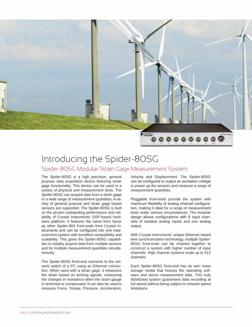
The Spider-80SG is a high precision, general purpose data acquisition device featuring strain gage functionality. This device can be used in a variety of physical and measurement tests. The Spider-80SG can acquire data from a strain gage or a wide range of measurement quantities. A va-riety of general purpose and strain gage based sensors are supported. The Spider-80SG is built on the proven outstanding performance and reli-ability of Crystal Instruments’ DSP-based hard-ware platform. It features the same form factor as other Spider-80X front-ends from Crystal In-struments and can be configured into one mea-surement system with excellent compatibility and scalability. This gives the Spider-80SG capabili-ties to reliably acquire data from multiple sensors and for multiple measurement quantities simulta-neously.
The Spider-80SG front-end connects to the net-work switch of a PC using an Ethernet connec-tion. When used with a strain gage, it measures the strain based on arriving signals, measuring the changes in resistance when the strain gauge is stretched or compressed. It can also be used to measure Force, Torque, Pressure, Acceleration,
Velocity and Displacement. The Spider-80SG can be configured to output an excitation voltage to power up the sensors and measure a range of measurement quantities.
Pluggable front-ends provide the system with maximum flexibility of analog channel configura-tion, making it ideal for a range of measurement tests under various circumstances. The modular design allows configurations with 8 input chan-nels of isolated analog inputs and one analog output.
With Crystal Instruments’ unique Ethernet based time synchronization technology, multiple Spider-80SG front-ends can be chained together to construct a system with higher number of input channels. High channel systems scale up to 512 channels.
Each Spider-80SG front-end has its own mass storage media that houses the operating soft-ware and stores measurement data. This truly distributed system guarantees data recording at full speed without being subject to network speed limitations.
Introducing the Spider-80SG Spider-80SG Modular Strain Gage Measurement System
CRYSTALINSTRUMENTS.COM | PAGE 2
Dual Modes of ExcitationThe Spider-80SG is equipped with dual excitation modes. There is an option for Precision Excita-tion Voltage of ± 2.5V or ± 5V that can be used to excite a strain gage or a strain gage based sen-sor and measure the minute change in resistance accurately. It is also equipped with a user con-figurable DC power supply of 2.5V, 5V and 10V which can be used as an excitation voltage for a wide variety of sensors.
Remote SensingThe Spider-80SG has been tested to work on strain gages up to 1000 ft away from the ana-lyzer using the remote sensing feature. Using an 18AWG 5 conductor cable to measure the excita-tion voltage using remote sensing and changes in output voltage, the error was measured to be less than 1.5% for up to signal frequencies of 10 KHz.
Use with Vibration ControllerThe Spider-80SG’s compatibility allows it to be chained together with Spider–80X front-end(s), extending the capabilities of the Spider-80SG to read and record general purpose measurements simultaneously while performing a vibration con-trol test.
High Performance Hardware CapabilitySince all the processing and data recording is executed locally inside the Spider-80SG, the front-end can be located far from the host PC and
closer to the test article. This flexibility in loca-tion prevents the measurement results from be-ing affected by the network connection limitations and other environmental errors. This decentral-ized and distributed structure greatly reduces the noise and electrical interference in the system. One PC can monitor and control multiple Spider-80SG front-ends over the network. With wireless network routers, the PC can easily connect to the Spider-80SG remotely via Wi-Fi.
Multiple Front-ends & Time SynchronizationThe Spider-80SG is built on IEEE 1588 time syn-chronization technology. The Spider-80SG front-ends on the same network can be synchronized with up to 50 ns accuracy, which guarantees ±1 degree cross channel phase match up to 20 kHz. With such unique technology and high-speed Ethernet data transfer capability, the distributed components on the network truly act as one inte-grated system.
Black Box Mode: Run without PCThe Spider-80SG can operate in Black Box mode, which allows the measurements to take place without a PC. In this mode, a PC is used only to configure the Spider-80SG system before the system starts operating and to download data after the test is complete. During the test, the sys-tem can operate according to a preset schedule or is controlled from a variety of external devices, such as a tablet or iPad.
Product Applications
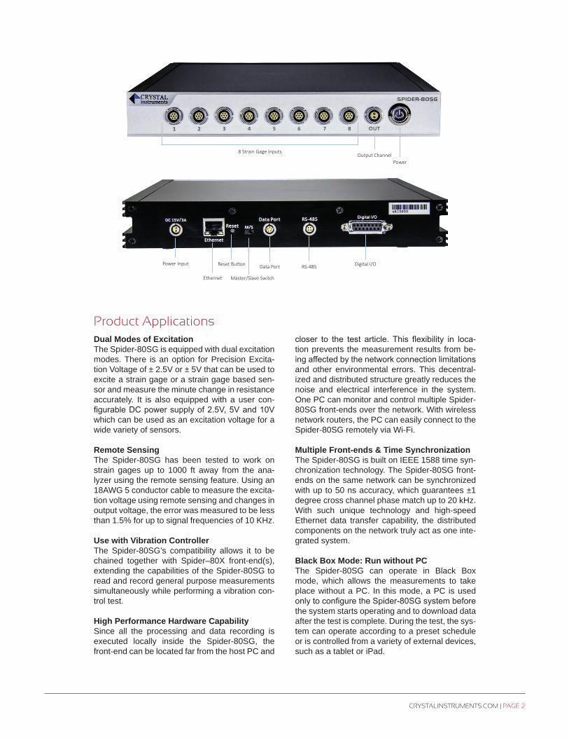
8 Strain Gage InputsOutput Channel
Power
Power Input
Ethernet
Reset Button
Master/Slave Switch
Data Port RS-485 Digital I/O
PAGE 3 | CRYSTALINSTRUMENTS.COM
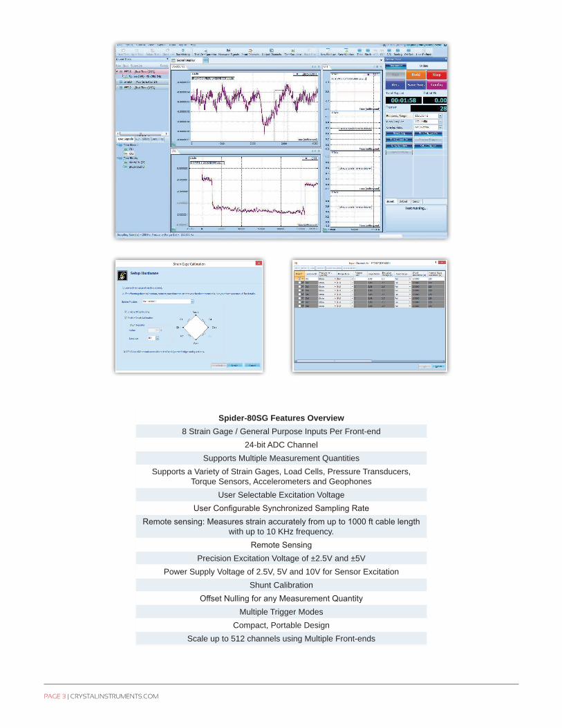
Spider-80SG Features Overview8 Strain Gage / General Purpose Inputs Per Front-end
24-bit ADC ChannelSupports Multiple Measurement Quantities
Supports a Variety of Strain Gages, Load Cells, Pressure Transducers, Torque Sensors, Accelerometers and Geophones
User Selectable Excitation VoltageUser Configurable Synchronized Sampling Rate
Remote sensing: Measures strain accurately from up to 1000 ft cable length with up to 10 KHz frequency.
Remote SensingPrecision Excitation Voltage of ±2.5V and ±5V
Power Supply Voltage of 2.5V, 5V and 10V for Sensor ExcitationShunt Calibration
Offset Nulling for any Measurement QuantityMultiple Trigger Modes
Compact, Portable DesignScale up to 512 channels using Multiple Front-ends
CRYSTALINSTRUMENTS.COM | PAGE 4
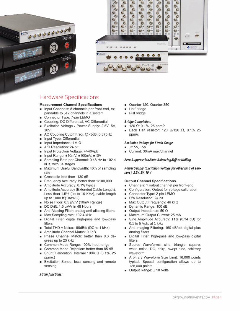
Measurement Channel Specifications Input Channels: 8 channels per front-end, ex-
pandable to 512 channels in a system Connector Type: 7-pin LEMO Coupling: DC Differential, AC Differential Excitation Voltage / Power Supply: 2.5V, 5V,
10V AC Coupling Cutoff Freq. @ -3dB: 0.375Hz Input Type: Differential Input Impedance: 1M Ω A/D Resolution: 24 bit Input Protection Voltage: +/-40Vpk Input Range: ±10mV, ±100mV, ±10V Sampling Rate per Channel: 0.48 Hz to 102.4
kHz, with 54 stages Maximum Useful Bandwidth: 46% of sampling
rate Crosstalk: less than -130 dB Frequency Accuracy: better than 1/100,000 Amplitude Accuracy: 0.1% typical Amplitude Accuracy (Extended Cable Length):
Less than 1.5% (up to 10 KHz), cable length up to 1000 ft (18AWG)
Noise Floor: 0.5 μV/V (10mV Range) DC Drift: 1.5 μV/V in 48 Hours Anti-Aliasing Filter: analog anti-aliasing filters Max Sampling rate: 102.4 kHz Digital Filter: digital high-pass and low-pass
filters Total THD + Noise: -90dBfs (DC to 1 kHz) Amplitude Channel Match: 0.1dB Phase Channel Match: better than 0.3 de-
grees up to 20 kHz Common Mode Range: 100% input range Common Mode Rejection: better than 85 dB Shunt Calibration: Internal 100K Ω (0.1%, 25
ppm/c) Excitation Sense: local sensing and remote
sensing
Strain functions:
Quarter-120, Quarter-350 Half bridge Full bridge
Bridge Completion: 120 Ω: 0.1%, 25 ppm/c Back Half resistor: 120 Ω/120 Ω, 0.1% 25
ppm/c
Excitation Voltage for Strain Gauge ±2.5V, ±5V Current: 30mA max/channel
Zero Suppression/Auto Balancing/Offset Nulling
Power Supply (Excitation Voltage for other kind of sen-sors): 2.5V, 5V, 10 V
Output Channel Specifications Channels: 1 output channel per front-end Configuration: Output for voltage calibration Connector Type: 2-pin LEMO D/A Resolution: 24 bit Max Output Frequency: 46 kHz Dynamic Range: 100 dB Output Impedance: 50 Ω Maximum Output Current: 25 mA Sine Amplitude Accuracy: ±1% (0.34 dB) for
0.1 to 5 Vpk, at 1 kHz Anti-Imaging Filtering: 160 dB/oct digital plus
analog filters Digital Filter: high-pass and low-pass digital
filters Source Waveforms: sine, triangle, square,
white noise, DC, chirp, swept sine, arbitrary waveform
Arbitrary Waveform Size Limit: 16,000 points typical. Special configuration allows up to 128,000 points.
Output Range: ± 10 Volts
Hardware Specifications
PAGE 5 | CRYSTALINSTRUMENTS.COM
Isolated Digital Input and Output Connector: 25-pin female D-SUB External Circuit Power Supply: 3.3 ‒ 12 VDC
(±10%) Internal Power: 12 VDC 400 mA Maximum Allowable Distance of Signal Exten-
sion: 50 meters
Inputs Input Format: opto-isolated input (compatible
with current-sink output) Number of Channels: 4 Input Resistance: 6.1 kΩ Input On Current: 2.0 mA or more Input Off Current: 0.16 mA or less Interrupt: 8 input signals are arranged into a
single interrupt output signal. An interrupt is generated either at the rising edge (HIGH-to-LOW transition) or falling edge (LOW-to-HIGH transition).
Outputs Output Format: opto-isolated input (current
sink output) Number of Channels: 4 Output Rating: output voltage 12 VDC max,
output current 100 mA per channel max Residual Voltage with Output On: 1.0 V or less
(Output current < 100 mA) Pulse Width: 47 ms Rise Time: 250 µs Fall Time: 50 µs
High Speed Data Port interfacing to Spider-NAS
Connector Type: 5-pin LEMO Maximum distance of cable: 2 meters Data Transfer Speed: Higher than 819.2 K
Sample/second
System Specifications On-Board Memory: 4 GB non-volatile flash
memory, 32 MB DRAM Power Management: active and sleep mode Ethernet: 100Base-T, RJ45 female connector
supports connection to PC or network switch Internal Clock: maintains date and time System Disaster Recovery: dedicated reset
pin. Watch-dog based recovery can be en-abled.
Cooling: no cooling fan required
Network Protocols & IEEE 1588 Time Syn-chronizationMultiple Spider front-ends are synchronized through IEEE 1588 protocol. The synchroniza-tion accuracy is better than ±50 ns with a certi-fied network switch. The data acquired by all the measurement channels will be synchronized. The phase match between channels across dif-ferent Spider-Strain front-ends is within 1.0 de-gree at 20 kHz.
IPv4 Protocol Stack: ICMP, IP, UDP, TCP, IGMP
IPv4 Configuration: manual or via DHCP IEEE 1588v2 Protocol: PTP Ordinary clock,
with both E2E and P2P synchronization sup-ported and hardware level timestamp for PTP event messages
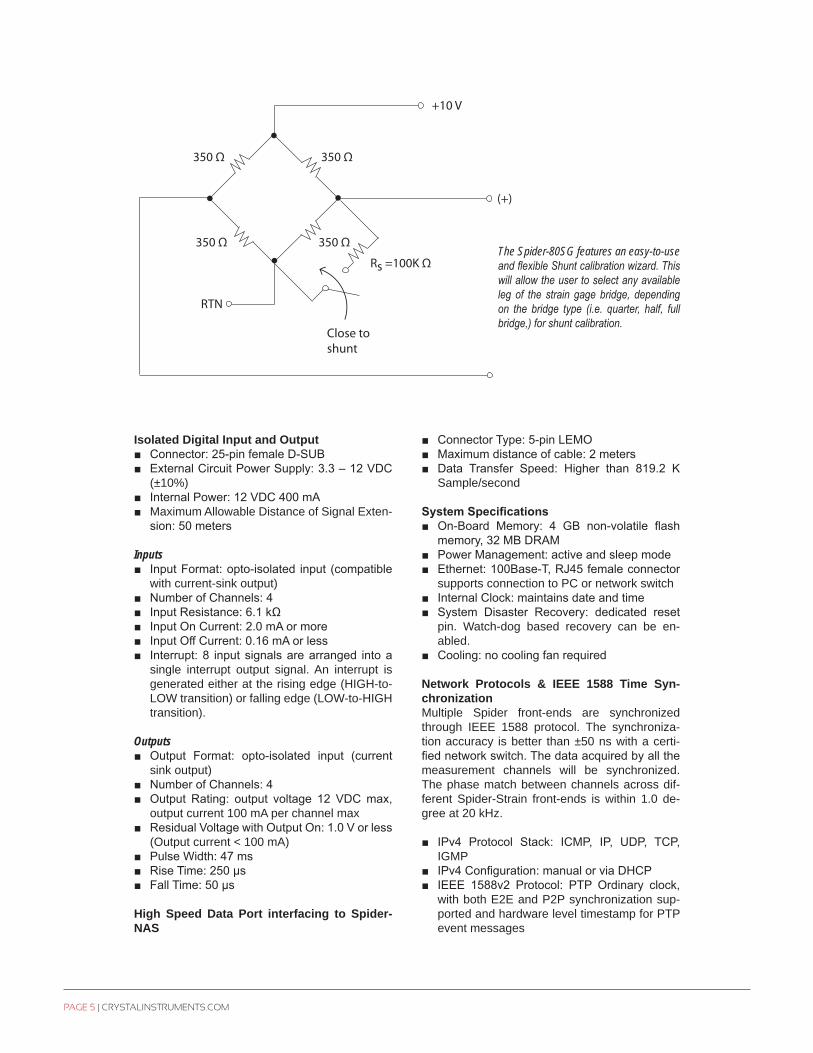
350 Ω
350 Ω350 Ω
350 Ω
RTN
+10 V
(+)
Rs =100K Ω
Close to shunt
The Spider-80SG features an easy-to-use and flexible Shunt calibration wizard. This will allow the user to select any available leg of the strain gage bridge, depending on the bridge type (i.e. quarter, half, full bridge,) for shunt calibration.
CRYSTALINSTRUMENTS.COM | PAGE 6
Power Specifications Power Supply: external DC power External DC Power: AC adaptor accepts
100 to 240 VAC (50/60 Hz), DC power 15 V (±10%)/3 A
Power Consumption: less than 15 watts
Environmental & General SpecificationsEnclosure: sealed metal box, electrical safety compliant, rugged metal design, shock proof with integrated protective holster and internal EMI shielding.
Size : 240 x 35 x 310 mm (w x h x l) Weight: 1.87 kg Electromagnetic Compatibility and Sensi-
tivity: EN 61326:1997+A1:1998+A2:2001, EN61000-3-2: 2000, EN61000-3-3: 1995+A1:2001
Operating Temperature:-10 to +55 °C Storage Temperature -20 to +70 °C Shock: 50 g’s, 315 in/sec, tested at 6 sides,
non-operational test Vibration: 5 - 500 Hz, 0.3 gRMS, tested at 3
sides, operational test Vibration: 5 - 500 Hz, 2.42 gRMS, tested at 3
sides, non-operational test
Compatible Measurement Quantities & Sug-gested SensorsMultiple sensors of various measurement quan-tities are supported with the Spider-80SG. The following list gives an overview of measurement quantities with sample sensors that are support-ed. The actual list of compatible sensors contains much more than specified here.
Acceleration – Dytran 7603B, 7503, 7523A2,
Endevco 7264C, Kistler Type 8395A, DTS 6DX PRO Series
Force – Omega LCM 901, Futek FFP350 Torque – Omega TQ-130 Series, Futek
TDD400, Futek TRS300, Futek TAT200, TAT420
Pressure – Omega PX309 series, Measure-ment Spec EB100, Futek PMP927
Angular Velocity – DTS ARS Pro-300, ARS Pro-1500, ARS Pro-8K, ARS Pro-18k
Displacement – Omega E2E-3DC Series Magnetic Field – Analog Devices AD22151 Sound Pressure – InvenSense ICS40618 Strain – Configurable as Quarter, Half or Full
Bridge
Hardware/Software Compatibility Specifica-tionsThe Spider-80SG can be used with the following devices:
1. Spider-80X2. Spider-813. Spider-NAS4. Spider-HUB
Modes of Operation:1. Standalone mode as a General Purpose Data
acquisition device2. In conjunction with Spider-80X for General
purpose Data Acquisition3. In conjunction with Spider-80X for general
data acquisition during vibration control.
For further software specifications related to the Spider-80SG, please refer to the EDM DSA or EDM VCS specification documents by Crystal Instruments.
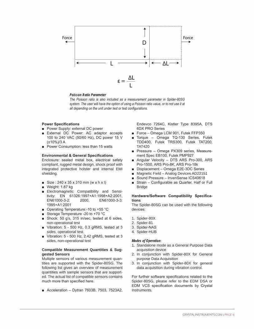
L ∆L
Force ForceD
ε = ∆LL
Poisson Ratio ParameterThe Poisson ratio is also included as a measurement parameter in Spider-80SG system. The user will have the option of using a Poisson ratio value, or to not use it at all depending on the unit under test or test configurations.
CRYSTAL INSTRUMENTS 2370 OWEN STREETSANTA CLARA, CA 95054 (USA)
PHONE: +1-408-986-8880 FAX: +1-408-834-7818
EMAIL: [email protected]
To find a distributor near you, please visit our website:
© 2016 Crystal Instruments Corporation. All Rights Reserved. 11/2016
Notice: This document is for informational purposes only and does not set forth any warranty, expressed or implied, concerning any equipment, equipment feature, or service offered or to be offered by Crystal Instruments. Crystal Instruments reserves the right to make changes to this document at any time, without notice, and assumes no responsibility for its use. This informational document describes features that may not be currently available. Contact a Crystal Instruments sales representative for information on features and product availability.


