Download - Swisspump Sewage 50hz
Sewage Pumps 50Hz
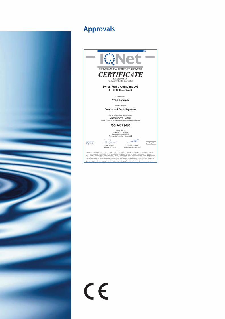
Approvals
René Wasmer
President of IQNet
Theodor Zahner
Managing Director SQS
CERTIFICATEIQNet and SQS
hereby certify that the organization
Certified area
Field of activity
has implemented and maintains a
Management Systemwhich fulfills the requirements of the following standard
ISO 9001:2008
Scope No: 29
Issued on: 2008-12-20
Validity date: 2011-12-19
Registration Number: CH-32160
Whole company
Swiss Pump Company AGCH-3645 Thun-Gwatt
Pumps- and Controlsystems
IQNet Partners*:
AENOR Spain AFNOR Certification France AIB-Vinçotte International Belgium ANCE Mexico APCER Portugal CISQ Italy CQC China
CQM China CQS Czech Republic Cro Cert Croatia DQS Holding GmbH Germany DS Denmark ELOT Greece FCAV Brazil
FONDONORMA Venezuela HKQAA Hong Kong China ICONTEC Colombia IMNC Mexico Inspecta Certification Finland IRAM Argentina
JQA Japan KFQ Korea MSZT Hungary Nemko AS Norway NSAI Ireland PCBC Poland Quality Austria Austria RR Russia SII Israel
SIQ Slovenia SIRIM QAS International Malaysia SQS Switzerland SRAC Romania TEST St Petersburg Russia TSE Turkey YUQS Serbia
IQNet is represented in the USA by: AFNOR Certification, CISQ, DQS Holding GmbH and NSAI Inc.
* The list of IQNet partners is valid at the time of issue of this certificate. Updated information is available under www.iqnet-certification.com
3
Contents
Strong Series page 4
N Series 8
NA Series 14
H Series 20
MA Series 28
GP Series 48
SG Series 52
SW Series 58
DC Series 60
DA Series 68
DW Series 74
V Series 80
LA Series 86
Str
on
g •
Se
rie
s
4
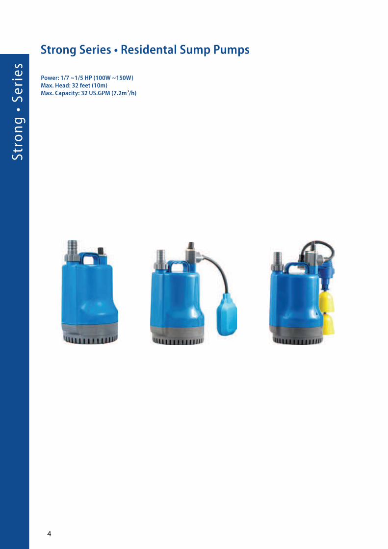
Strong Series • Residental Sump Pumps
Power: 1/7 ~1/5 HP (100W ~150W)Max. Head: 32 feet (10m)Max. Capacity: 32 US.GPM (7.2m³/h)

5
Feature
• An excellent architectural design:
stunning streamline design, space saving and robust.
• High capacity performance: Highly efficient 100 W and
150 W motors with low amperage providing energy
savings.
• Weather-proof AAS plastics, Built-in overheat protector,
IP 68 quality approved (highest submersible standard)
waterproof structure, equipped with mechanical seal,
oil seal, and epoxy resin sealed cable base. Durability
bulit into design provides a longer life expectancy.
• Precies aluminum motor housing design, lash water
resistance.
• New vortex design with superior performance.
• Outlet discharge is available in ½ inch, ¾ inch,
and 1 inch.
Application
• Tank Water Circulating, Gardening, Dewatering, Water
Recycles, Water Supply or Drainage. Commercial
Beautification Ponds and residential Ponds.
• Note: Not suitable for seawater, strong acid or alkali liquid.
Definition of model
Strong - 100 F
Type watt float
F : float switch
FV: Vertical float Switch
Specification
�
Strong 100FV Semi open impeller

Str
on
g •
Se
rie
s
6
Performance Curves
Strong 100
Strong 150
Strong 150FStrong 100 Semi open impeller
7
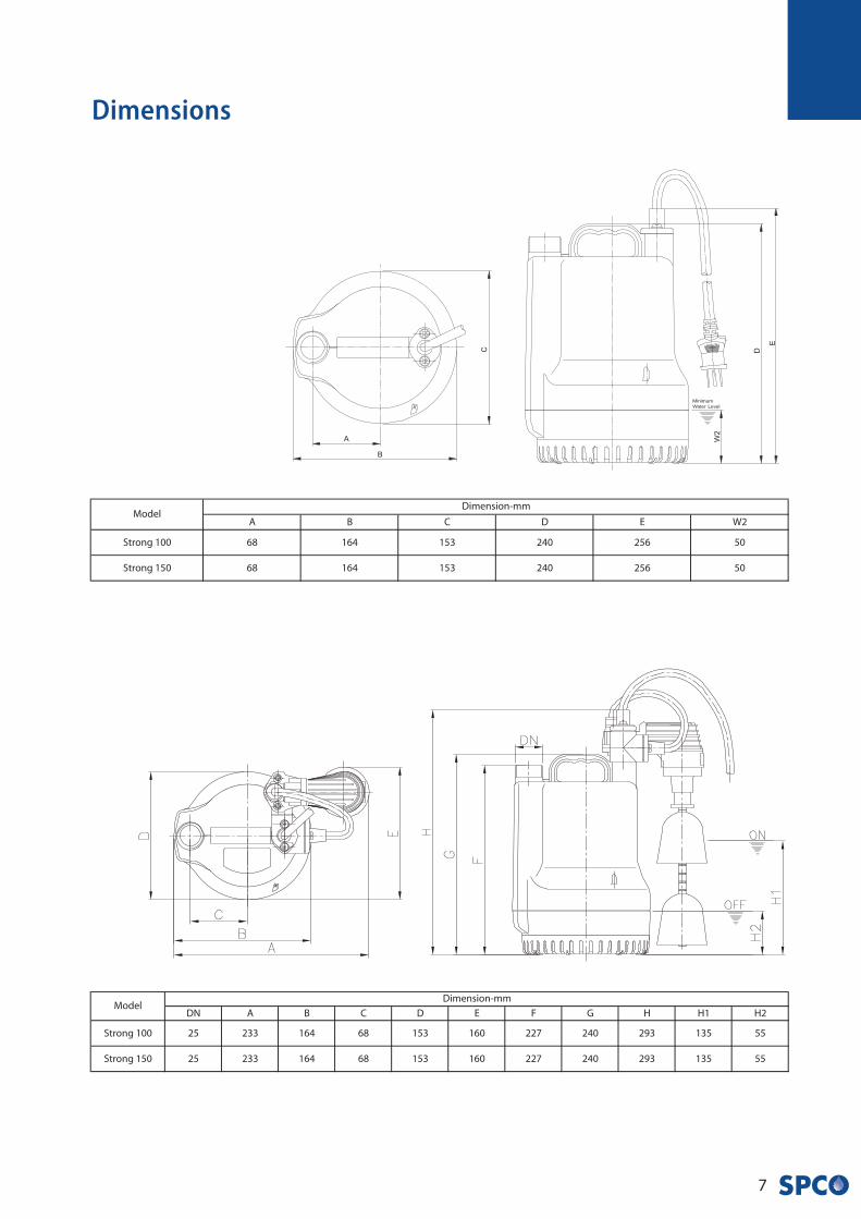
Dimensions
N •
Se
rie
s
8
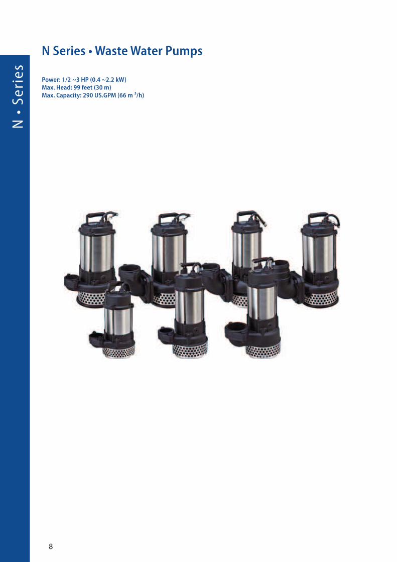
N Series • Waste Water Pumps
Power: 1/2 ~3 HP (0.4 ~2.2 kW)Max. Head: 99 feet (30 m)Max. Capacity: 290 US.GPM (66 m ³/h)
9
Feature
Application
Definition of model
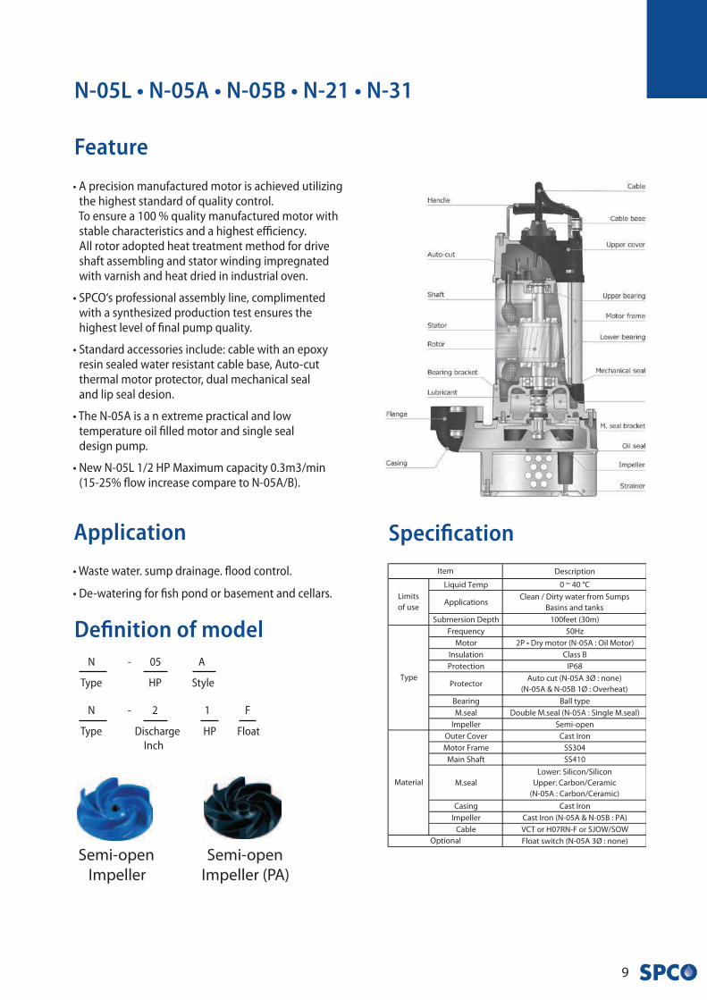
• A precision manufactured motor is achieved utilizing the highest standard of quality control. To ensure a 100 % quality manufactured motor with stable characteristics and a highest efficiency. All rotor adopted heat treatment method for drive shaft assembling and stator winding impregnated with varnish and heat dried in industrial oven.
• SPCO‘s professional assembly line, complimented with a synthesized production test ensures the highest level of final pump quality.
• Standard accessories include: cable with an epoxy resin sealed water resistant cable base, Auto-cut thermal motor protector, dual mechanical seal and lip seal desion.
• The N-05A is a n extreme practical and low temperature oil filled motor and single seal design pump.
• New N-05L 1/2 HP Maximum capacity 0.3m3/min (15-25% flow increase compare to N-05A/B).
• Waste water. sump drainage. flood control.
• De-watering for fish pond or basement and cellars.
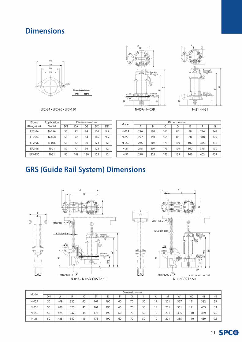
N-05L • N-05A • N-05B • N-21 • N-31
N - 05 A
Type HP Style
Specification
N - 2 1 F
Type Discharge HP Float
Inch
�
Semi-open
Impeller (PA)
Semi-open
Impeller
N •
Se
rie
s
10
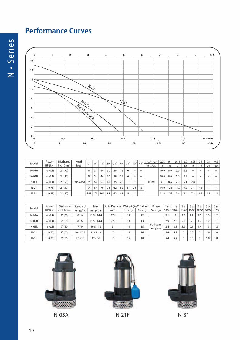
Performance Curves
N-31
N-21
N-31N-05A • N-05B
N-05A N-21F
N-05L
11
Dimensions
GRS (Guide Rail System) Dimensions
EF2-84 • EF2-96 • EF3-130
N-05A • N-05B: GRS T2-50 N-21: GRS T2-50
NorminalWater Level
MinimumWater Level
A
B
D
H1
W1
W2
M
C
EF
G
H2
DN
K Guide Bars
M10*40L-2
M16*120L-2
NorminalWater Level
MinimumWater Level
AB
D
H1
W1
M
C
EF
G
H2
DN
K Guide Bars
M10*40L-2
M16*120L-2
W2
N-21 • N-31
NorminalWater Level
MinimumWater Level
AB
C
G
FED
N-05A • N-05B
NorminalWater Level
MinimumWater Level
AB
C
G
FED

N •
Se
rie
s
12
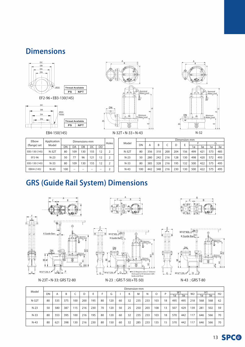
N-32T • N-23 • N-33 • N-43
Specification
Performance Curves
N-33N-23
N-33N-32TN-23
N-43
Enclosed-chanel
Impeller
Semi open
Impeller
13
GRS (Guide Rail System) Dimensions
Dimensions
N-32T • N-33 • N-43
NorminalWater Level
MinimumWater Level
AB
C
GF
E
D
NorminalWater Level
MinimumWater Level
AB
C
GF
ED
DN
DN
N-32
N-23T • N-33: GRS T2-80
NorminalWater Level
MinimumWater Level
AB
D
H1
W1
M
C
EF
G
H2
DN
K Guide Bars
M10*40L-2
M16*120L-4
W2
O P
N
NorminalWater Level
MinimumWater Level
AB
D
H1
W1
M
C
EF
G
H2
DN
K Guide Bars
M10*40L-2
M16*120L-4
W2
O P
N
NorminalWater Level
MinimumWater Level
AB
D
H1
W1
M
C
F
E
G
H2
DN
K Guide Bars
M16*120L-4
W2
O P
N
N-23 : GRS T-50(+TE-50) N-43 : GRS T-80
EB4-150(145)
EF2-96 • EB3-130(145)
NA
• S
eri
es
14
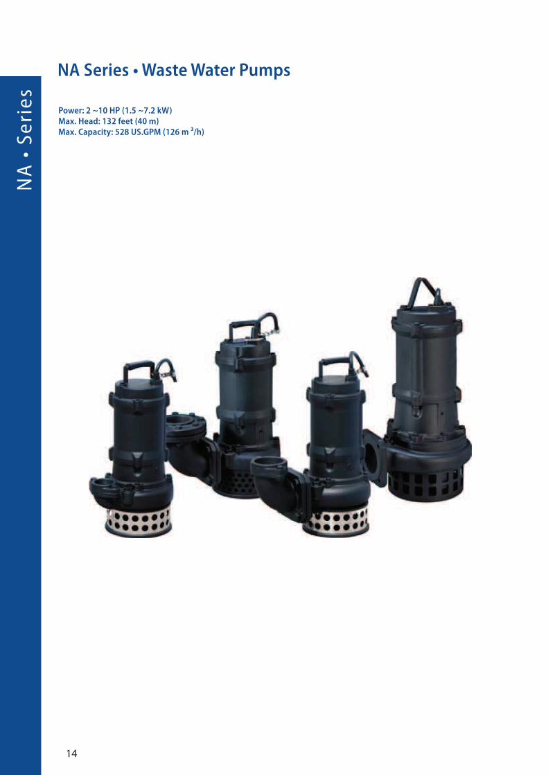
NA Series • Waste Water Pumps
Power: 2 ~10 HP (1.5 ~7.2 kW)Max. Head: 132 feet (40 m)Max. Capacity: 528 US.GPM (126 m ³/h)
15
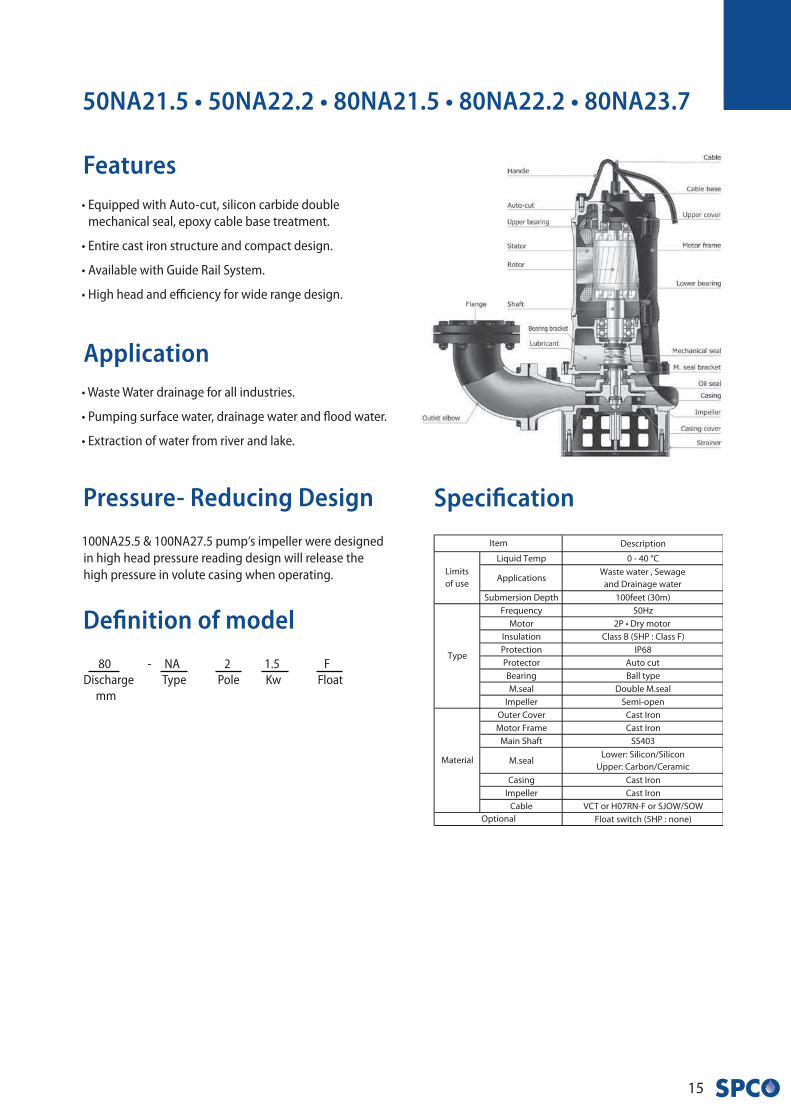
Features
Application• Waste Water drainage for all industries.
• Pumping surface water, drainage water and flood water.
• Extraction of water from river and lake.
Pressure- Reducing Design
100NA25.5 & 100NA27.5 pump‘s impeller were designed
in high head pressure reading design will release the
high pressure in volute casing when operating.
50NA21.5 • 50NA22.2 • 80NA21.5 • 80NA22.2 • 80NA23.7
Definition of model
80 - NA 2 1.5 F
Discharge Type Pole Kw Float
mm
Specification
• Equipped with Auto-cut, silicon carbide double
mechanical seal, epoxy cable base treatment.
• Entire cast iron structure and compact design.
• Available with Guide Rail System.
• High head and efficiency for wide range design.

NA
• S
eri
es
16
Performance Curves
80NA22.2
80NA23.780NA22.280NA21.5
50NA21.5
50NA22.2
50NA21.5 80NA23.7F Semi-open
Impeller
17
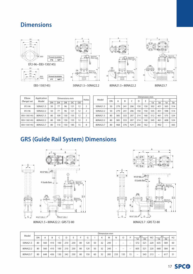
GRS (Guide Rail System) Dimensions
Dimensions
80NA23.7 : GRS T2-80
NorminalWater Level
MinimumWater Level
AB
DH
1W
1
M
C
EF
G
H2
DN
K Guide Bars
M10*40L-2
M16*120L-4
W2
O P
N
NorminalWater Level
MinimumWater Level
AB
C
GF
E
DN
D
80NA23.7
NorminalWater Level
MinimumWater Level
A
B
C
GFE
DN
D
80NA21.5 • 80NA22.250NA21.5 • 50NA22.2
NorminalWater Level
MinimumWater Level
A
B
C
GF
E
DND
EB3-150(145)
EF2-96 • EB3-130(145)
80NA21.5 • 80NA22.2 : GRS T2-80
NorminalWater Level
MinimumWater Level
A
B
D
H1
W1
M
C
EF
G
H2
DN
K Guide Bars
M10*40L-2
M16*120L-2
W2
M16*120L-2
NA
• S
eri
es
18
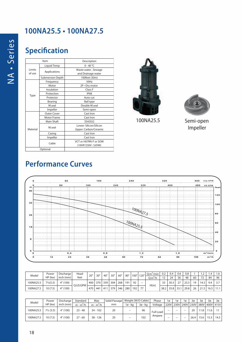
Specification
100NA25.5 • 100NA27.5
Performance Curves
100NA25.5
100NA27.5
100NA25.5
Semi-open
Impeller
19
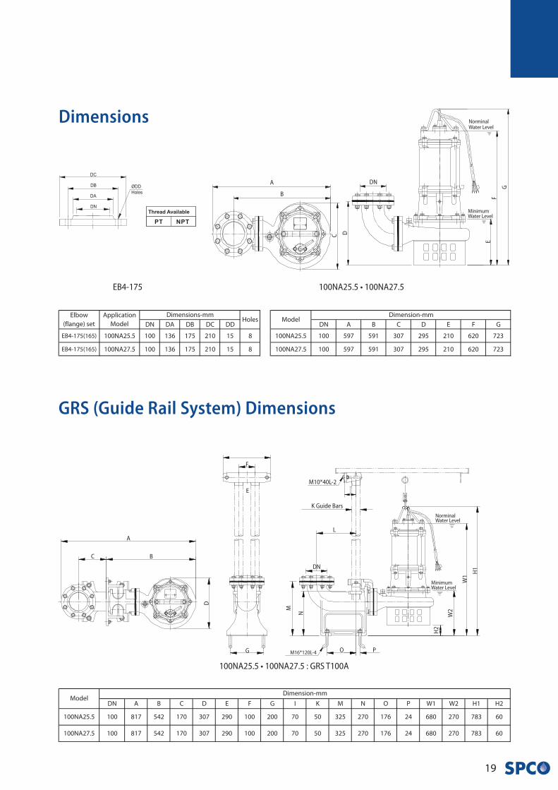
Dimensions
GRS (Guide Rail System) Dimensions
100NA25.5 • 100NA27.5
NorminalWater Level
MinimumWater Level
A
B
C
G
FE
DN
D
100NA25.5 • 100NA27.5 : GRS T100A
E
NorminalWater Level
MinimumWater Level
A
B
D
H1
W1
M
C
F
G
H2
DN
K Guide Bars
M10*40L-2
M16*120L-4
W2
O P
N
L
EB4-175
H •
Se
rie
s
20
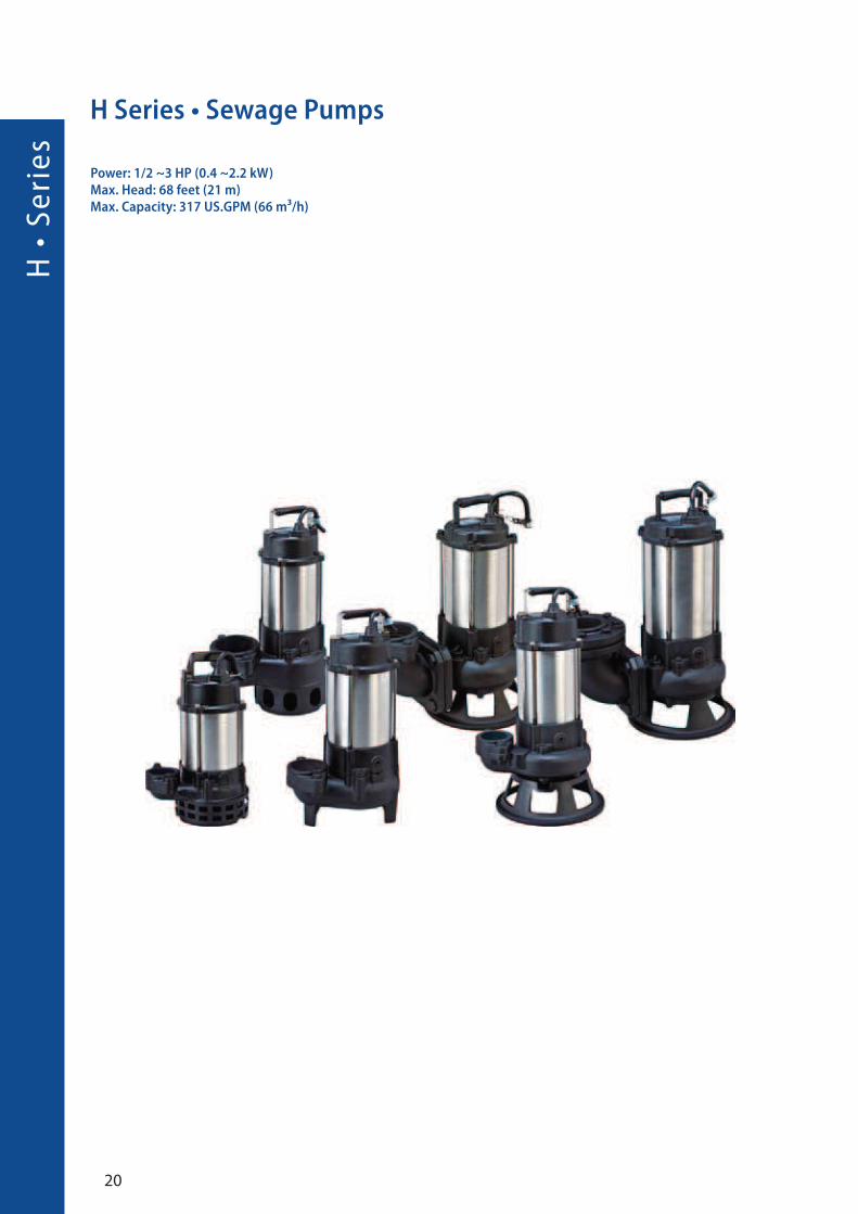
H Series • Sewage Pumps
Power: 1/2 ~3 HP (0.4 ~2.2 kW)Max. Head: 68 feet (21 m)Max. Capacity: 317 US.GPM (66 m³/h)

21
• A precision manufactured motor is achieved utilizing
the highest standard of quality control. To ensure a
100% quality manufactured motor with stable
characteristics and a highest efficiency. All rotor
adopted heat treatment method for drive shaft
assembling and stator winding impregnated with
varnish and heat dried in industrial oven.
• SPCO‘s professional assembly line, complimented
with a synthesized production test ensures the
highest level of final pump quality.
• Standard accessories include: cable with an epoxy
resin sealed water-resistant cable base, AC thermal
motor protector, dual mechanical seal and lip seal
design.
• U type Vortex impeller or P type cutter impeller
design, handle any wastewater or sewage
application with the best de-watering efficiency.
• Full product line range, providing the best service,
with high impact resistance and light weight, for
easy of service and transportation.
• The H-05A is an extremely practical and low
temperature oil filled motor and single seal design
pump.
• Drainage of sewage from the building basements, hotel industry, wastes water from factories.
• Drainage of sewage from industrial process factories.
• Emptying of septic tanks, cesspits and sewage pump stations.
• Pumping surface and drainage water from garages and sprinkler systems.
Application
Features
H-05A • H-05U • H-21U • H-31U
Specification
Definition of model
H - 2 1 T U F
type Discharge HP Style Impeller Float
Inch
H - 05 A
type 1/2HP Style

H •
Se
rie
s
22
Performance Curves
H-05A H-31UH-05U
H-05U
H-31U
H-21U
H-05A
Semi-open
Impeller (PA)
U Type
Impeller
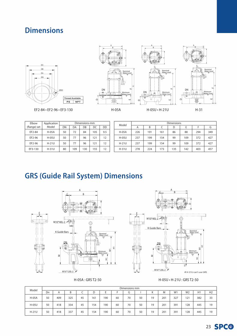
23
GRS (Guide Rail System) Dimensions
H-05A
NorminalWater Level
MinimumWater Level
AB
C
GF
E
DN
D
NorminalWater Level
MinimumWater Level
AB
C
G
FE
DN
D
NorminalWater Level
MinimumWater Level
AB
C
GF
E
DN
D
H-05U • H-21U H-31
H-05A : GRS T2-50
NorminalWater Level
MinimumWater Level
AB
D
H1
W1
M
C
EF
G
H2
DN
K Guide Bars
M10*40L-2
M16*120L-2
W2
NorminalWater Level
MinimumWater Level
A
B
D
H1
W1
M
C
EF
G
H2
DN
K Guide Bars
M10*40L-2
M16*120L-2
W2
H-05U • H-21U : GRS T2-50
EF2-84 • EF2-96 • EF3-130
Dimensions

H •
Se
rie
s
24
Specification
Performance Curves
H-33U
2 (1.5) 25
25
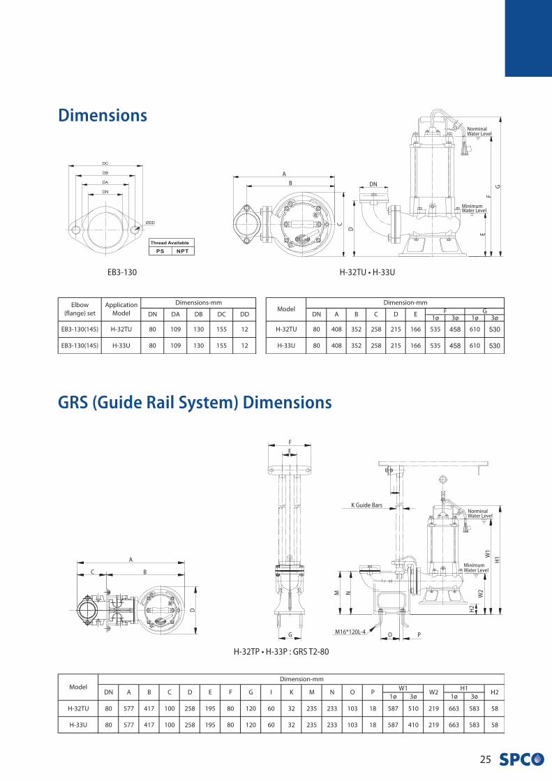
H-32TU • H-33U
H-33U
H-32TU
U Type
Impeller
25
Dimensions
GRS (Guide Rail System) Dimensions
H-32TU • H-33U
NorminalWater Level
MinimumWater Level
A
B
C
G
FE
DN
D
H-32TP • H-33P : GRS T2-80
A
B
D
C
458 530
458 530
EB3-130
NorminalWater Level
MinimumWater Level
H1W
1
M
E
G
H2
K Guide Bars
M16*120L-4
W2
O P
N
F
H •
Se
rie
s
26
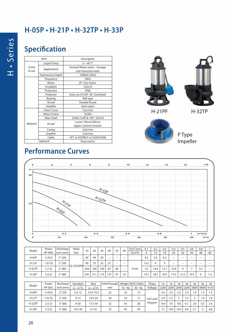
Specification
Performance Curves
H-05P • H-21P • H-32TP • H-33P
�
H-32TPH-21PF
P Type
Impeller
H-33P
H-32TPH-21PH-05P
27
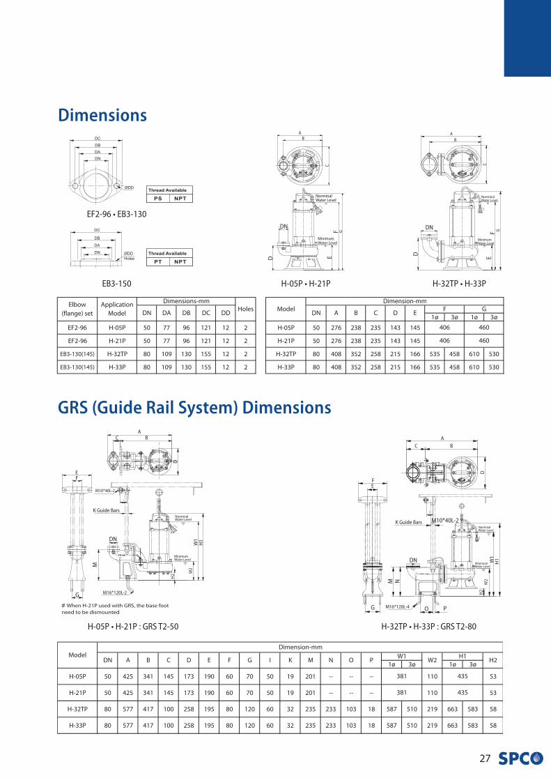
Dimensions
GRS (Guide Rail System) Dimensions
H-05P • H-21P : GRS T2-50
NorminalWater Level
MinimumWater Level
AB
D
H1
W1
M
C
EF
G
H2
DN
K Guide Bars
M16*120L-2
W2
M10*40L-2
EB3-150
EF2-96 • EB3-130
NorminalWater Level
MinimumWater Level
A
B
C
GFE
DN
D
H-32TP • H-33PH-05P • H-21P
NorminalWater Level
MinimumWater Level
A
B
C
GFE
DN
D
H-32TP • H-33P : GRS T2-80
NorminalWater Level
MinimumWater Level
A
B
D
H1W
1
M
C
FE
G
H2
DN
K Guide Bars
M16*120L-4
W2
O P
N
M10*40L-2
MA
• S
eri
es
28
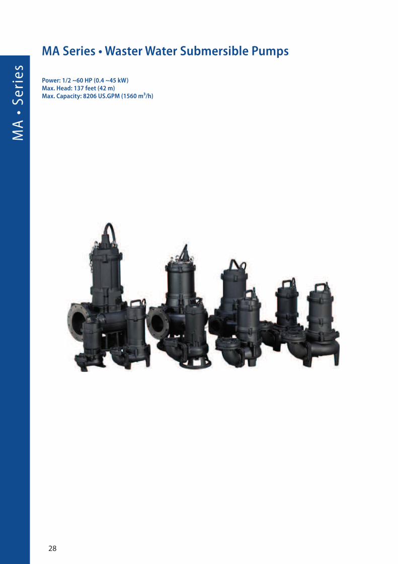
MA Series • Waster Water Submersible Pumps
Power: 1/2 ~60 HP (0.4 ~45 kW)Max. Head: 137 feet (42 m)Max. Capacity: 8206 US.GPM (1560 m³/h)
29
• Drainage of waste water from the attenuation tank, purifying tank and sewage tank in water treatment plant.
• Drainage of waste water containing fibrous additives from leather factory, dyeing factory and food processing factory.
• sewage management, accumulated water, septic tank, stock farm.
• pumping sewage from single and multifamily dwellings.
• pumping sewage from hotels, restaurants, schools and pulblic buildings.
Application
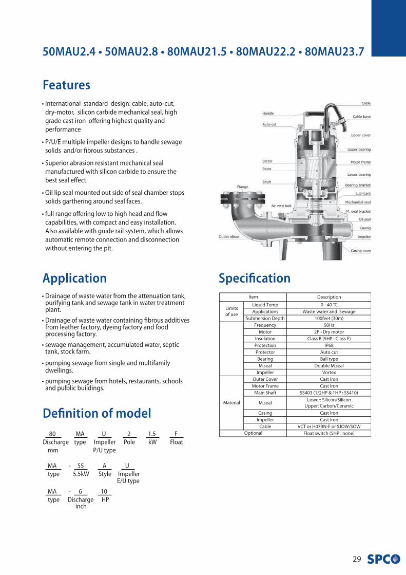
Features• International standard design: cable, auto-cut,
dry-motor, silicon carbide mechanical seal, high
grade cast iron offering highest quality and
performance
• P/U/E multiple impeller designs to handle sewage
solids and/or fibrous substances .
• Superior abrasion resistant mechanical seal
manufactured with silicon carbide to ensure the
best seal effect.
• Oil lip seal mounted out side of seal chamber stops
solids garthering around seal faces.
• full range offering low to high head and flow
capabilities, with compact and easy installation.
Also available with guide rail system, which allows
automatic remote connection and disconnection
without entering the pit.
50MAU2.4 • 50MAU2.8 • 80MAU21.5 • 80MAU22.2 • 80MAU23.7
Specification
Definition of model
80 MA U 2 1.5 F
Discharge type Impeller Pole kW Float
mm P/U type
MA - 55 A U
type 5.5kW Style Impeller E/U type
MA - 6 10
type Discharge HP inch
MA
• S
eri
es
30
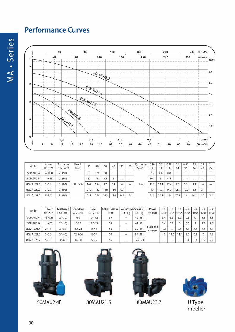
Performance Curves
80MAU23.7
80MAU21.5
50MAU2.4
80MAU22.2
80MAU23.7
50MAU2.8
80MAU21.550MAU2.4F U Type
Impeller
31
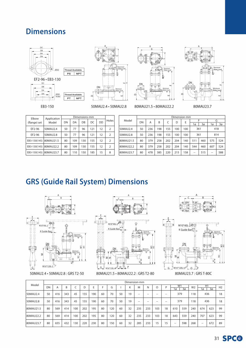
GRS (Guide Rail System) Dimensions
Dimensions
50MAU2.4 • 50MAU2.8 : GRS T2-50 80MAU21.5 • 80MAU22.2 : GRS T2-80 80MAU23.7 : GRS T-80C
ø ø
NorminalWater Level
MinimumWater Level
AB
C
GF
E
DN
D
80MAU23.7
NorminalWater Level
MinimumWater Level
AB
C
GF
E
DN
D
80MAU21.5 • 80MAU22.250MAU2.4 • 50MAU2.8
NorminalWater Level
MinimumWater Level
AB
C
GFE
DN
D
EB3-150
EF2-96 • EB3-130
NorminalWater Level
MinimumWater Level
A
B
D
H1
W1
M
C
EF
G
H2
DN
K Guide Bars
M16*120L-4
W2
O P
N
M10*40L-2
NorminalWater Level
MinimumWater Level
AB
D
H1
W1
M
C
EF
G
H2
DN
K Guide Bars
M16*120L-2
W2
M10*40L-2
NorminalWater Level
MinimumWater Level
AB
D
H1
W1
M
C
EF
G
H2
DN
K Guide Bars
M10*40L-2
M16*120L-4
W2
O P
N
MA
• S
eri
es
32
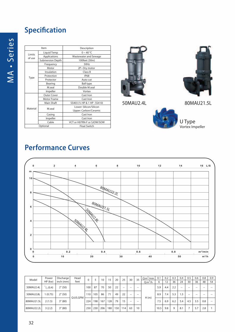
Specification
Performance Curves
80MAU21.5L
50MAU2.4L
80MAU22.2L
50MAU2.8L
50MAU2.4L 80MAU21.5L
U Type Vortex Impeller
33
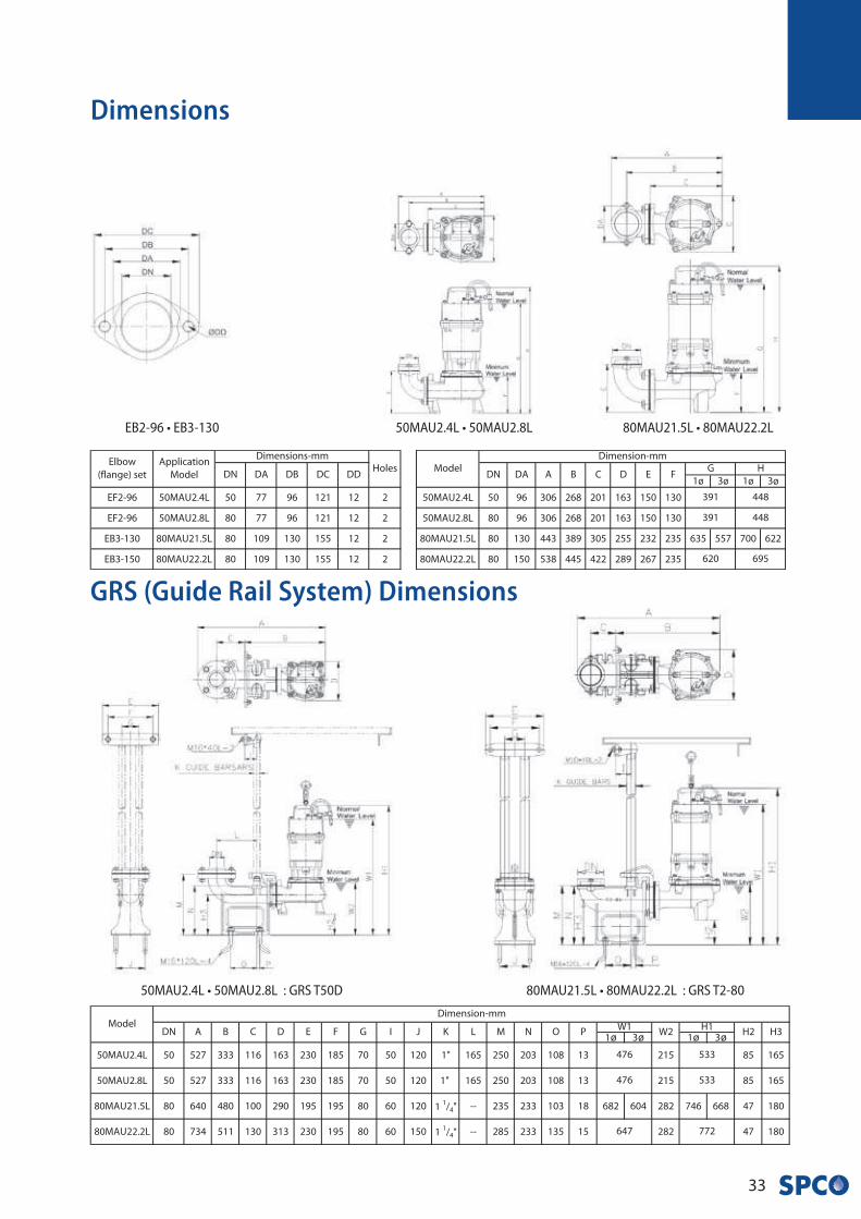
Dimensions
ø ø ø ø
80MAU21.5L • 80MAU22.2L : GRS T2-8050MAU2.4L • 50MAU2.8L : GRS T50D
GRS (Guide Rail System) Dimensions
80MAU21.5L • 80MAU22.2LEB2-96 • EB3-130 50MAU2.4L • 50MAU2.8L
MA
• S
eri
es
34
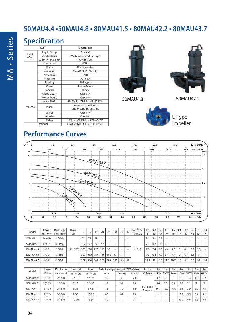
50MAU4.4 •50MAU4.8 • 80MAU41.5 • 80MAU42.2 • 80MAU43.7
Specification
Performance Curves
50MAU4.8
80MAU41.5
50MAU4.4
80MAU42.2
80MAU43.7
50MAU4.8
80MAU42.2
U Type
Impeller

35
GRS (Guide Rail System) Dimensions
Dimensions
50MAU4.4 • 50MAU4.8 80MAU41.5 80MAU22.2 • 80MAU23.7
50MAU4.4 • 50MAU4.8 : GRS T-50D 80MAU41.5 : GRS T2-80 80MAU22.2 • 80MAU23.7 : GRS T-80C
NorminalWater Level
MinimumWater Level
AB
D
H1
W1
M
C
EF
G
H2
K Guide Bars
M16*120L-4
W2
M10*40L-2
N
O P
NorminalWater Level
MinimumWater Level
A
B
D
H1
W1
M
C
FE
G
H2
DN
K Guide Bars
M16*120L-4
W2
O P
N
NorminalWater Level
MinimumWater Level
AB
D
H1W1
M
C
EF
G
H2
DN
K Guide Bars
M10*40L-2
M16*120L-4
W2
O P
N
EB3-150(145)
EB2-96 • EB3-130(145)
NorminalWater Level
MinimumWater Level
AB
C
GF
E
DN
D
NorminalWater Level
MinimumWater Level
AB
C
GF
E
DN
D
NorminalWater Level
MinimumWater Level
AB
C
GF
E
DN
D

MA
• S
eri
es
36
80MAP21.5 • 80MAP22.2
Specification
Performance Curves
80MAP21.5
80MAP22.2
80MAP21.5
80MAP22.2
P Type
Impeller

37
GRS (Guide Rail System) Dimensions
80MAP21.5 • 80MAP22.2
NorminalWater Level
MinimumWater Level
A
B
C
GF
E
DN
D
80MAP21.5 • 80MAP22.2 : GRS T2-80
A
B
D
C
ø ø
EB3-130
Dimensions
NorminalWater Level
MinimumWater Level
H1
W1
M
F
G
H2
K Guide Bars
M16*120L-2
W2
E
M16*120L-2
M10*40L-2
MA
• S
eri
es
38
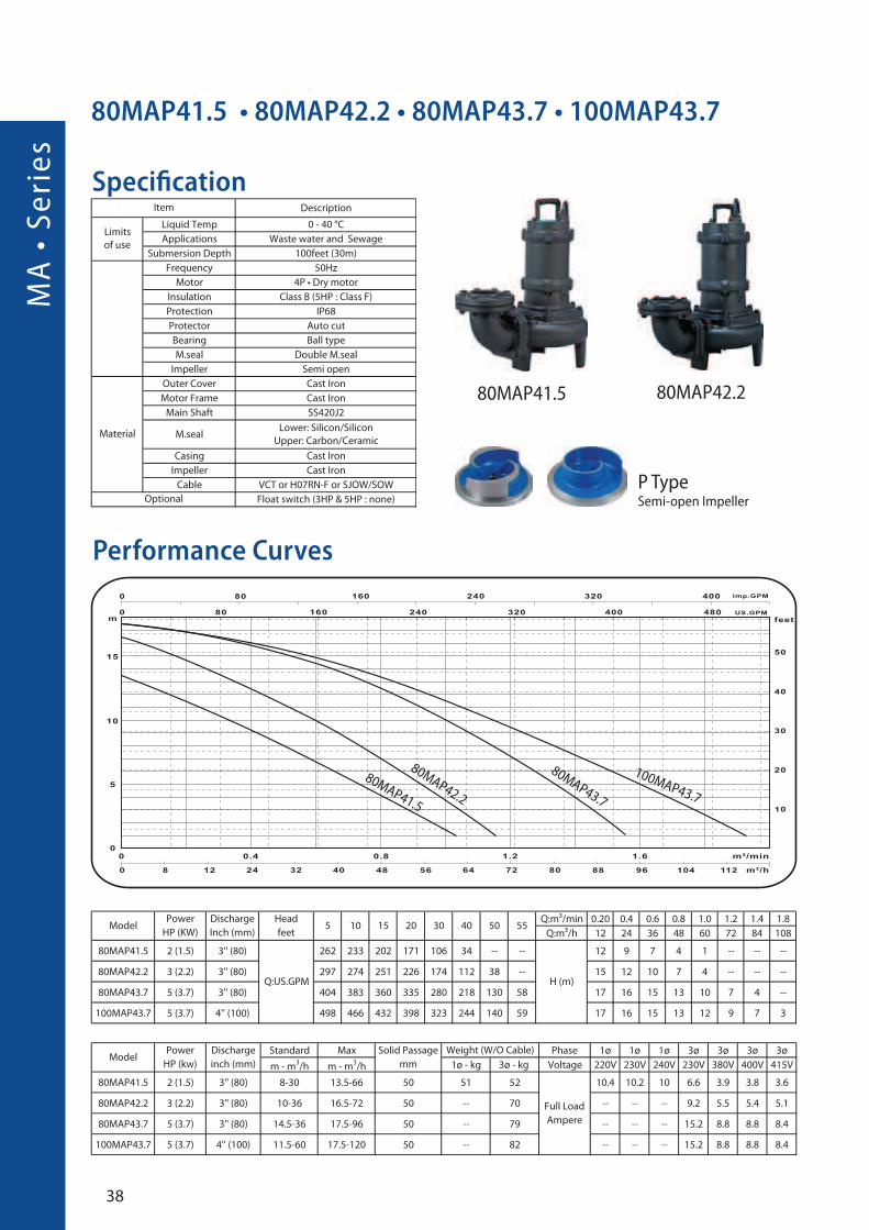
80MAP42.2
Specification
Performance Curves
80MAP41.5
100MAP43.7
80MAP43.7
80MAP42.2
80MAP41.5 • 80MAP42.2 • 80MAP43.7 • 100MAP43.7
80MAP41.5
P Type Semi-open Impeller
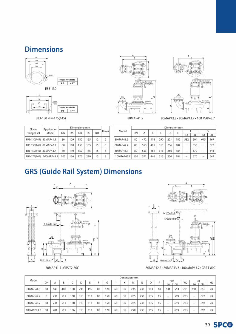
39
GRS (Guide Rail System) Dimensions
Dimensions
80MAP41.5 : GRS T2-80C
NorminalWater Level
MinimumWater Level
A
B
D
H1
W1
W2
M
C
FE
G
H2
DN
K Guide Bars
M16*120L-4 O P
N
ø ø
80MAP42.2 • 80MAP43.7 • 100 MAP43.780MAP41.5
NorminalWater Level
MinimumWater Level
AB
C
GF
ED
NorminalWater Level
MinimumWater Level
AB
C
GFE
D
DNDN
80MAP42.2 • 80MAP43.7 • 100 MAP43.7 : GRS T-80C
NorminalWater Level
MinimumWater Level
AB
D
H1
W1
M
C
EF
G
H2
DN
K Guide Bars
M10*40L-2
M16*120L-4
W2N
O P
EB3-150 • F4-175(145)
EB3-130
MA
• S
eri
es
40
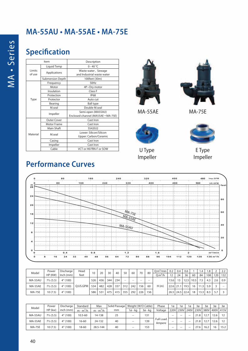
MA-55AU • MA-55AE • MA-75E
Specification
Performance Curves
•
MA-75EMA-55AE
MA-55AU
U Type
Impeller
MA-55AE MA-75E
E Type
Impeller
41
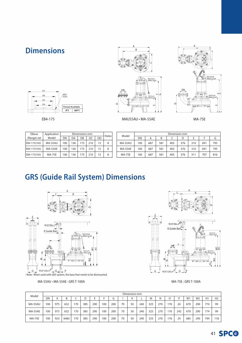
GRS (Guide Rail System) Dimensions
MA-55AU • MA-55AE : GRS T-100A
• Note: When used with GRS system, the base foot needs to be dismounted.
NorminalWater Level
MinimumWater Level
AB
D
H1
W1
W2M
C
EF
G
H2
DN
K Guide Bars
M16*120L-4 O P
N
M10*40L-2
MA-75E
NorminalWater Level
MinimumWater Level
AB
C
GFE
D
DN
MA-75E : GRS T-100A
NorminalWater Level
MinimumWater Level
AB
D
H1
W1
M
C
EF
G
H2
DN
K Guide Bars
M10*40L-2
M16*120L-4
W2
N
O P
L
I
Dimensions
MAU55AU • MA-55AE
NorminalWater Level
MinimumWater Level
A
B
C
GFED
DN
EB4-175
MA
• S
eri
es
42
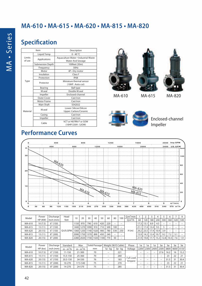
MA-610 • MA-615 • MA-620 • MA-815 • MA-820
Specification
Performance Curves
•
MA-820MA-815
MA-615
MA-610
MA-620
MA-610 MA-615 MA-820
Enclosed-channel
Impeller
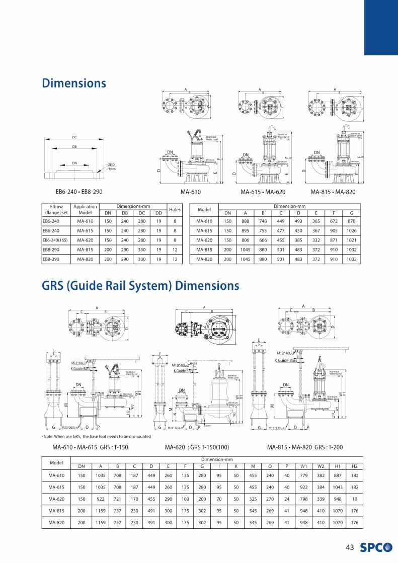
43
GRS (Guide Rail System) Dimensions
Dimensions
NorminalWater Level
MinimumWater Level
AB
CGF
E
DN
D
NorminalWater Level
MinimumWater Level
AB
C
GFE
DN
D
MA-615 • MA-620 MA-815 • MA-820MA-610
MA-610 • MA-615 GRS : T-150 MA-620 : GRS T-150(100) MA-815 • MA-820 GRS : T-200
• Note: When use GRS, the base foot needs to be dismounted
NorminalWater Level
MinimumWater Level
AB
D
H1
W1
M
C
EF
G
H2
DN
K Guide Bars
M12*40L-3
M16*120L-4
W2
O P
NorminalWater Level
MinimumWater Level
AB
D
H1
W1
M
C
EF
G
H2
DN
K Guide Bars
M16*120L-4
W2
O P
N
NorminalWater Level
MinimumWater Level
AB
D
H1
W1
M
C
EF
G
H2
K Guide Bars
M20*200L-4
W2
M12*40L-3
O P
I
M10*40L-2
DN
EB6-240 • EB8-290
NorminalWater Level
MinimumWater Level
AB
C
GFE
DN
D

MA
• S
eri
es
44
Specification
Performance Curves
MA-1050
MA-1040MA-1030S
MA-Large Series
45
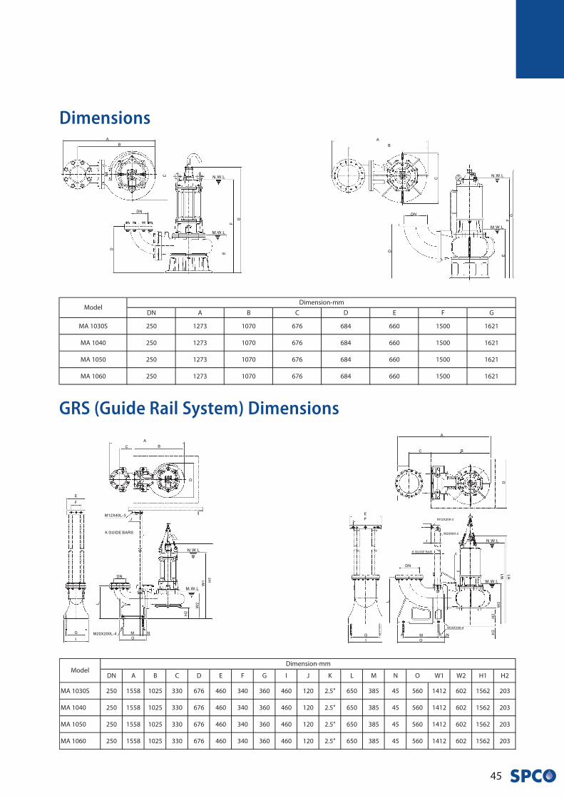
GRS (Guide Rail System) Dimensions
Dimensions
MA
• S
eri
es
46
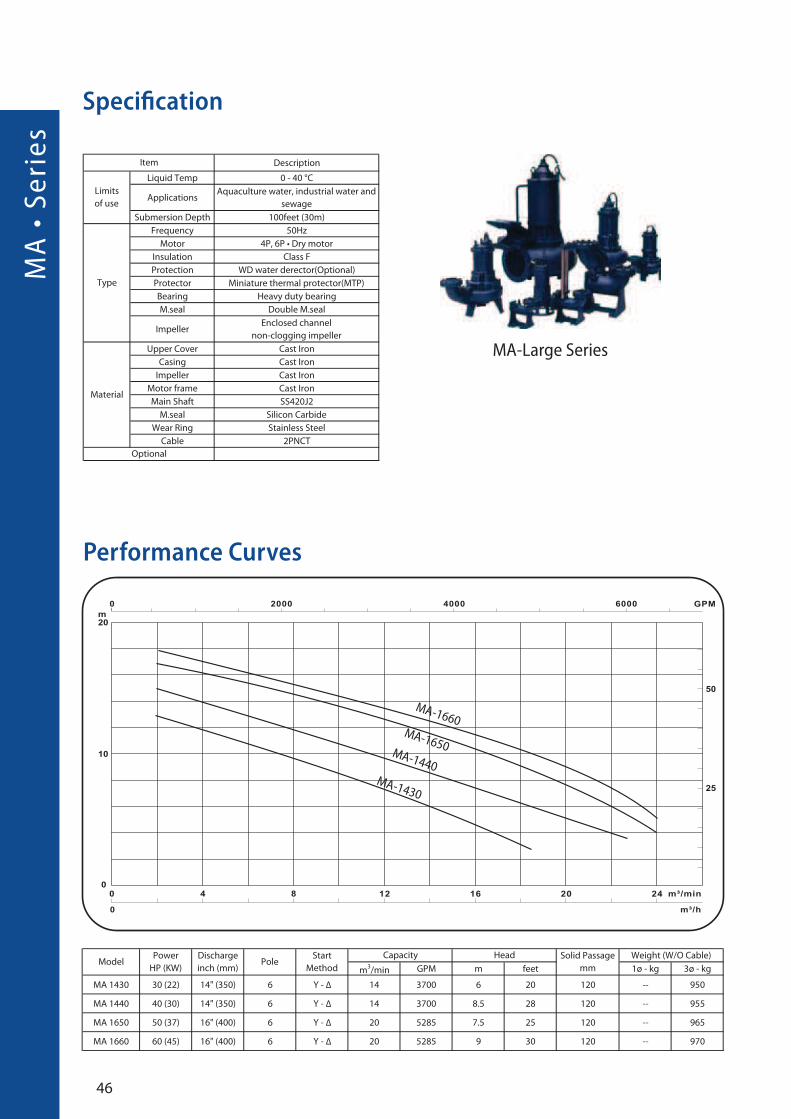
Performance Curves
MA-1660MA-1650
MA-1440MA-1430
Specification
MA-Large Series
47
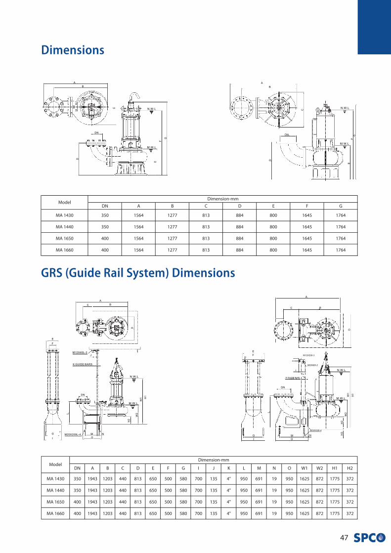
GRS (Guide Rail System) Dimensions
Dimensions
GP
• S
eri
es
48
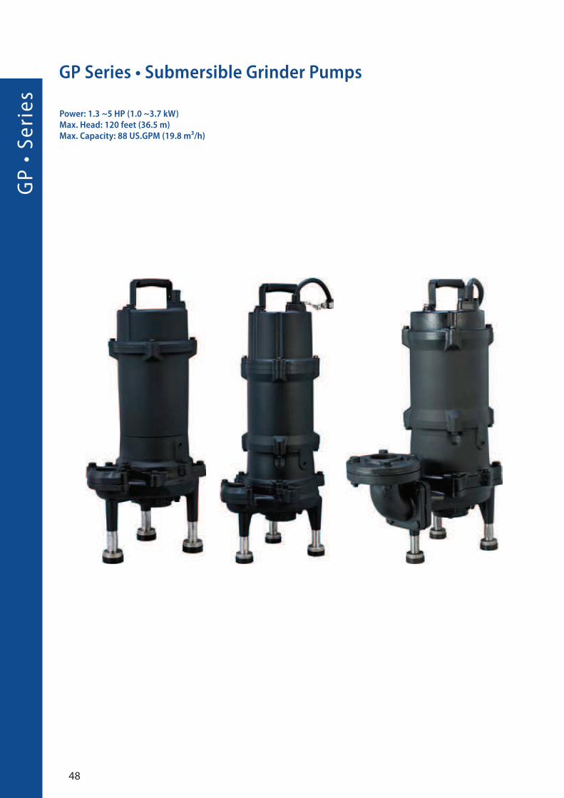
GP Series • Submersible Grinder Pumps
Power: 1.3 ~5 HP (1.0 ~3.7 kW)Max. Head: 120 feet (36.5 m)Max. Capacity: 88 US.GPM (19.8 m³/h)
49
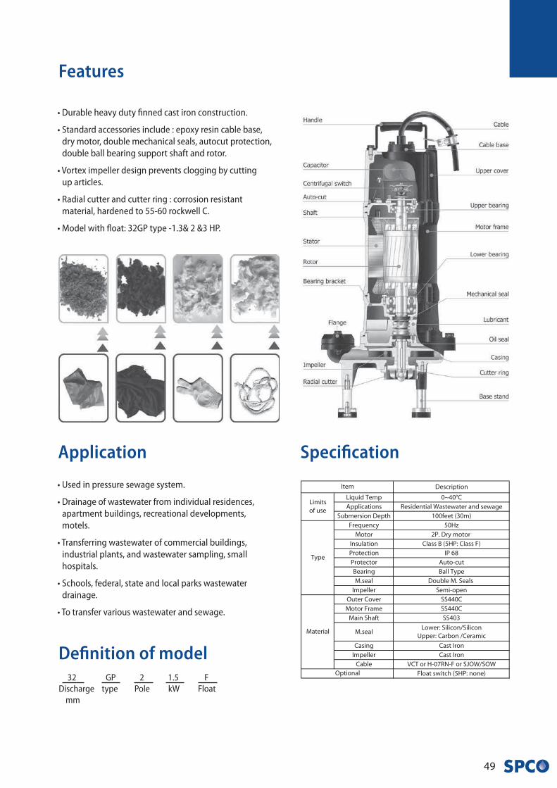
• Durable heavy duty finned cast iron construction.
• Standard accessories include : epoxy resin cable base,
dry motor, double mechanical seals, autocut protection,
double ball bearing support shaft and rotor.
• Vortex impeller design prevents clogging by cutting
up articles.
• Radial cutter and cutter ring : corrosion resistant
material, hardened to 55-60 rockwell C.
• Model with float: 32GP type -1.3& 2 &3 HP.
Application
Features
Definition of model
• Used in pressure sewage system.
• Drainage of wastewater from individual residences,
apartment buildings, recreational developments,
motels.
• Transferring wastewater of commercial buildings,
industrial plants, and wastewater sampling, small
hospitals.
• Schools, federal, state and local parks wastewater
drainage.
• To transfer various wastewater and sewage.
Specification
32 GP 2 1.5 F
Discharge type Pole kW Float
mm
GP
• S
eri
es
50
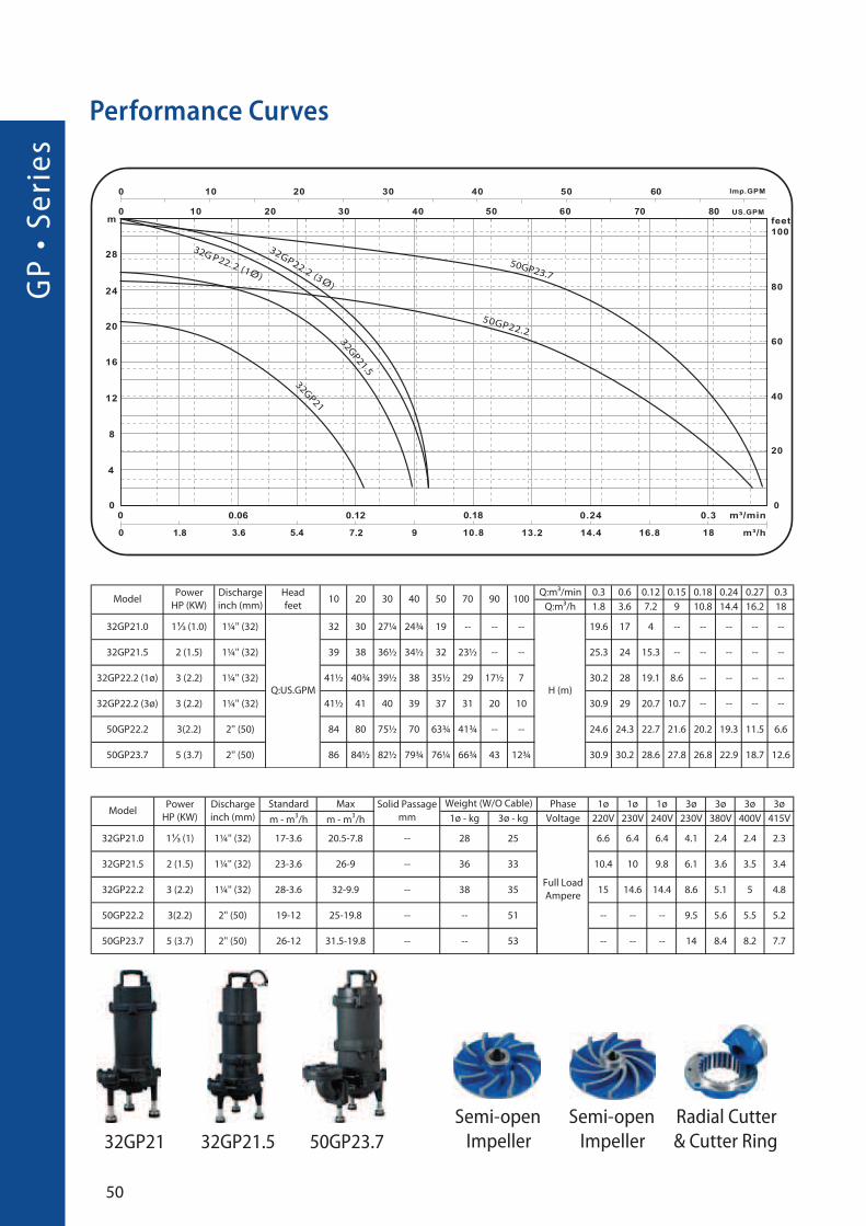
Performance Curves
�
�
Semi-open
Impeller
Semi-open
Impeller
Radial Cutter
& Cutter Ring50GP23.732GP21 32GP21.5
51
GRS (Guide Rail System) Dimensions
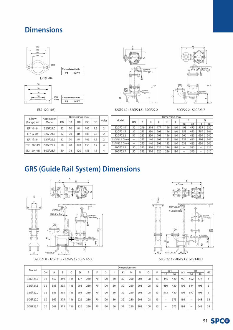
Dimensions
32GP21.0 • 32GP21.5 • 32GP22.2 : GRS T-50C
NorminalWater Level
MinimumWater Level
AB
D
H1
W1
W2
M
C
E
F
G
H2
DN
K Guide Bars
M16*120L-4 O P
N
M10*40L-2
¼
¼
¼
50GP22.2 • 50GP23.7: GRS T-80D
NorminalWater Level
MinimumWater Level
AB
D
H1
W1
M
C
EF
G
H2
DN
K Guide Bars
M10*40L-2
M16*120L-4
W2
N
O P
I
50GP22.2 • 50GP23.7
NorminalWater Level
MinimumWater Level
AB
C
GFE
D
DN
32GP21.0 • 32GP21.5 • 32GP22.2
NorminalWater Level
MinimumWater Level
AB
C
GF
ED
DN
EB2-120(105)
EF1¼ -84
SG
• S
eri
es
52
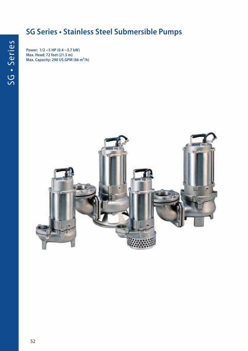
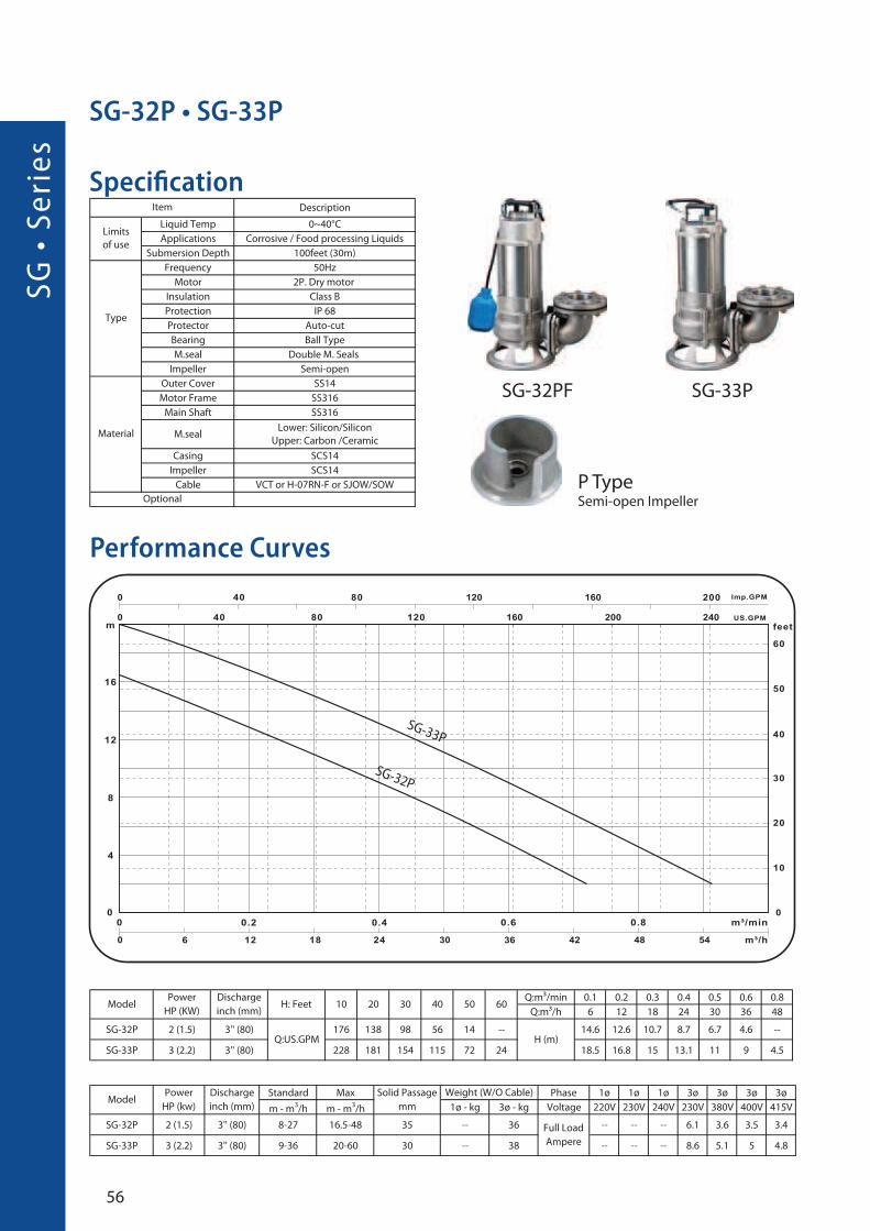
SG Series • Stainless Steel Submersible Pumps
Power: 1/2 ~5 HP (0.4 ~3.7 kW)Max. Head: 72 feet (21.5 m)Max. Capacity: 290 US.GPM (66 m³/h)
53
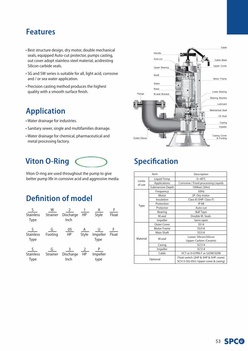
• Best structure design, dry motor, double mechanical
seals, equipped Auto-cut protector, pumps casting,
out cover adopt stainless steel material, acidresting
Silicon carbide seals.
• SG and SW series is suitable for all, light acid, corrosive
and / or sea water application.
• Precision casting method produces the highest
quality with a smooth surface finish.
Application
Features
Definition of model
• Water drainage for industries.
• Sanitary sewer, single and multifamilies drainage.
• Water drainage for chemical, pharmaceutical and
metal processing factory.
Viton O-ring are used throughout the pump to give
better pump life in corrosive acid and aggressive media
Viton O-Ring Specification
S W 2 1 A F
Stainless Strainer Discharge HP Style Float
Type Inch
S G 05 A U F
Stainless Footing HP Style Impeller Float
Type Type
S G 3 2 P
Stainless Strainer Discharge HP Impeller
Type Inch type
SG
• S
eri
es
54
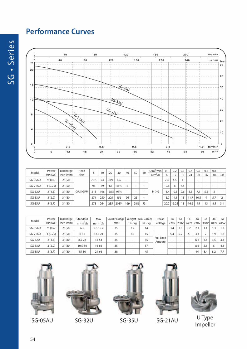
Performance Curves
SG-05AU
SG-35U
SG-33U
SG-32USG-21AUSG-05AU
SG-32U SG-35U SG-21AUU Type
Impeller
55
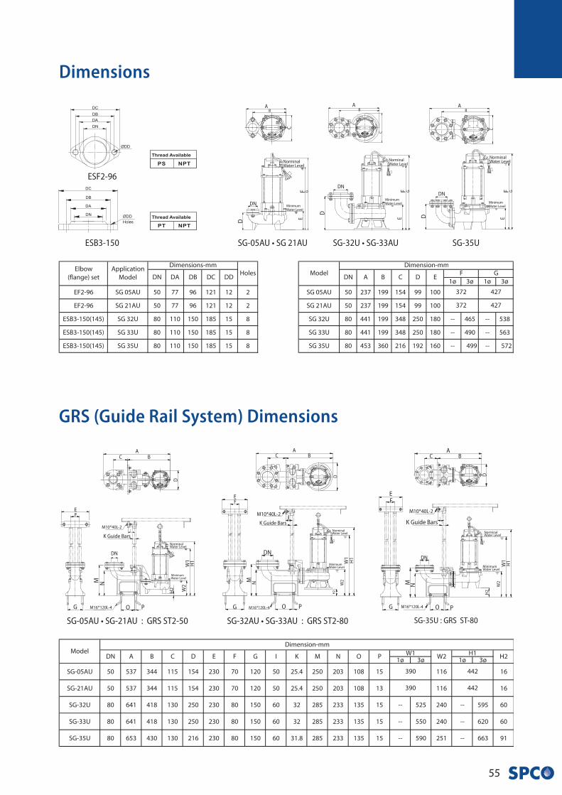
GRS (Guide Rail System) Dimensions
Dimensions
SG-05AU • SG-21AU : GRS ST2-50 SG-32AU • SG-33AU : GRS ST2-80 SG-35U : GRS ST-80
SG-35U
NorminalWater Level
MinimumWater Level
AB
C
GFE
DN
D
SG-32U • SG-33AU
NorminalWater Level
MinimumWater Level
AB
C
GFE
DN
D
SG-05AU • SG 21AU
NorminalWater Level
MinimumWater Level
AB
C
GFE
DN
DESB3-150
ESF2-96
NorminalWater Level
MinimumWater Level
AB
D
H1
W1
M
C
EF
G
H2
K Guide Bars
M16*120L-4
W2
M10*40L-2
O P
DN
N
NorminalWater Level
MinimumWater Level
AB
D
H1
W1
M
C
EF
G
H2
DN
K Guide Bars
M10*40L-2
M16*120L-4
W2
O P
N
NorminalWater Level
MinimumWater Level
AB
D
H1
W1
M
C
EF
G
H2
DN
K Guide Bars
M16*120L-4
W2
O P
N
IM10*40L-2
SG
• S
eri
es
56
Performance Curves
Specification
SG-33P
SG-32P • SG-33P
SG-33P
SG-32P
P Type Semi-open Impeller
SG-32PF
57
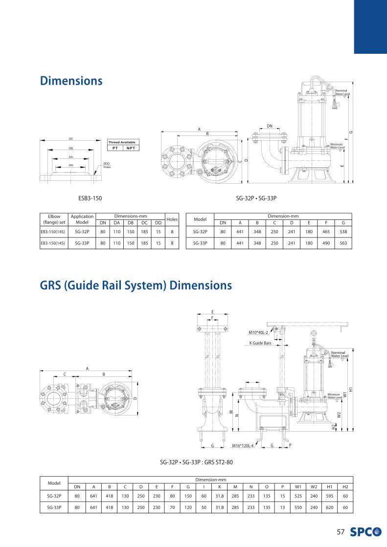
GRS (Guide Rail System) Dimensions
Dimensions
SG-32P • SG-33P
NorminalWater Level
MinimumWater Level
AB
C
GF
E
DN
D
SG-32P • SG-33P : GRS ST2-80
A
B
D
C
NorminalWater Level
MinimumWater Level
H1
W1
M
F
G
H2
K Guide Bars
M16*120L-4
W2
E
M10*40L-2
N
G P
ESB3-150
SW
• S
eri
es
58
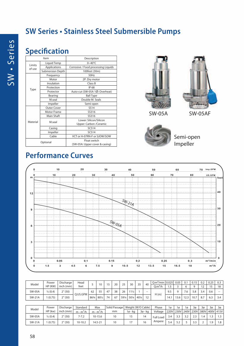
Performance Curves
Ø
Specification
SW-21A
SW-05A
SW-05AFSW-05A
Semi-open
Impeller
SW Series • Stainless Steel Submersible Pumps

59
GRS (Guide Rail System) Dimensions
Dimensions
SW-05A • SW-21A : GRS ST2-50
A
B
D
C
SW-05A • SW-21A
NorminalWater Level
MinimumWater Level
AB
C
GF
E
DN
D
ESF2-96
NorminalWater Level
MinimumWater Level
H1
W1
M
F
G
H2
K Guide Bars
M16*120L-4
W2
E
M10*40L-2
N
G P
DC
• S
eri
es
60
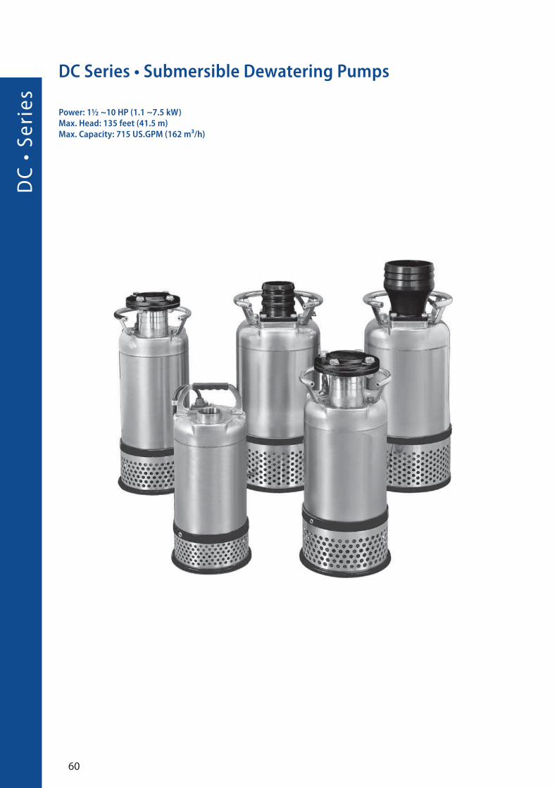
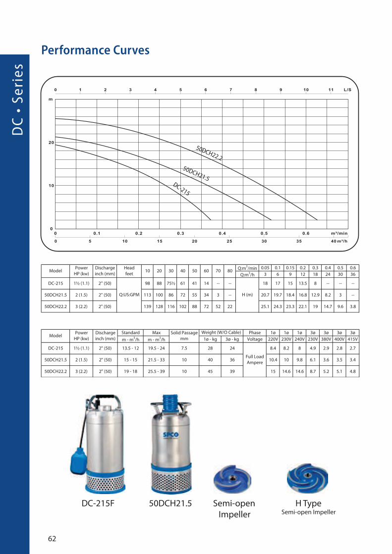
DC Series • Submersible Dewatering Pumps
Power: 1½ ~10 HP (1.1 ~7.5 kW)Max. Head: 135 feet (41.5 m)Max. Capacity: 715 US.GPM (162 m³/h)

61
Application
Features
Definition of model
• Civil engineering, dewatering of tunneling and ground
works, also for storm water sewers.
• Dewatering of fluids contain solid sediments.
• Easy of mobility for use by contractors, installers and
service industries.
• Complete Stainless steel outer cover of
DC 1.5 HP ~ 10 HP (1.1KW ~ 7.5KW) models provide
exceptional design, with light weight structure of less
than 175 Ibs (80Kg) and diameter of 11.2 inches
(286mm) that provide miniature outlook.
Civil engineering, dewatering of tunneling and ground
works, also for storm water sewers.
• Dewatering of fluids contain solid sediments.
• Easy of mobility for use by contractors, installers and
service industries.
DC-215 • 50DCH21.5 • 50DCH22.2
HiCr ImpellerHigh chrome alloy (HiCr) steel hardness of 55-65 HRC
impeller to stand high abrasive application.
Specification
�
100 - DC L 2 7.5
Discharge type Impeller Pole kW
mm type
DC - 2 15 F
type Discharge HP Float inch
DC
• S
eri
es
62
Performance Curves
50DCH22.2
50DCH21.5DC-215
DC-215F Semi-open
Impeller
H Type Semi-open Impeller
50DCH21.5
63
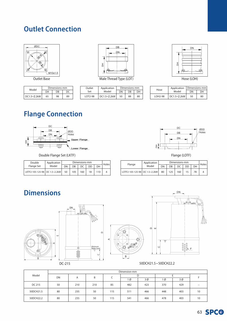
Outlet Connection
Flange Connection
~2 ~2 ~2
Dimensions
Outlet Base Male Thread Type (LOT) Hose (LOH)
Double Flange Set (LKTF) Flange (LOTF)
50DCH21.5 • 50DCH22.2DC-215
MinimumWater Level
B
E
D
C
A
DN

DC
• S
eri
es
64
Performance Curves
Specification
100DCL23.7
80DCN23.7
80DCN22.280DCN21.5
N/L Type Enclosed-channel Impeller
80DCN21.5 100DCL23.7

65
Outlet Connection
~3. ~3.
~3. ~3.
Flange Connection
~ ~~
Dimensions
Outlet Base Male Thread Type (LOT) Hose (LOH)
Flange (LOF) Central & Upper Flange (LKC)Upper Flange (LKF) Central Flange (LOC)
80DCN21.5 • 80DCN22.2 • 80DCN23.7 • 100DCL23.7Cassing Cover
DC
• S
eri
es
66
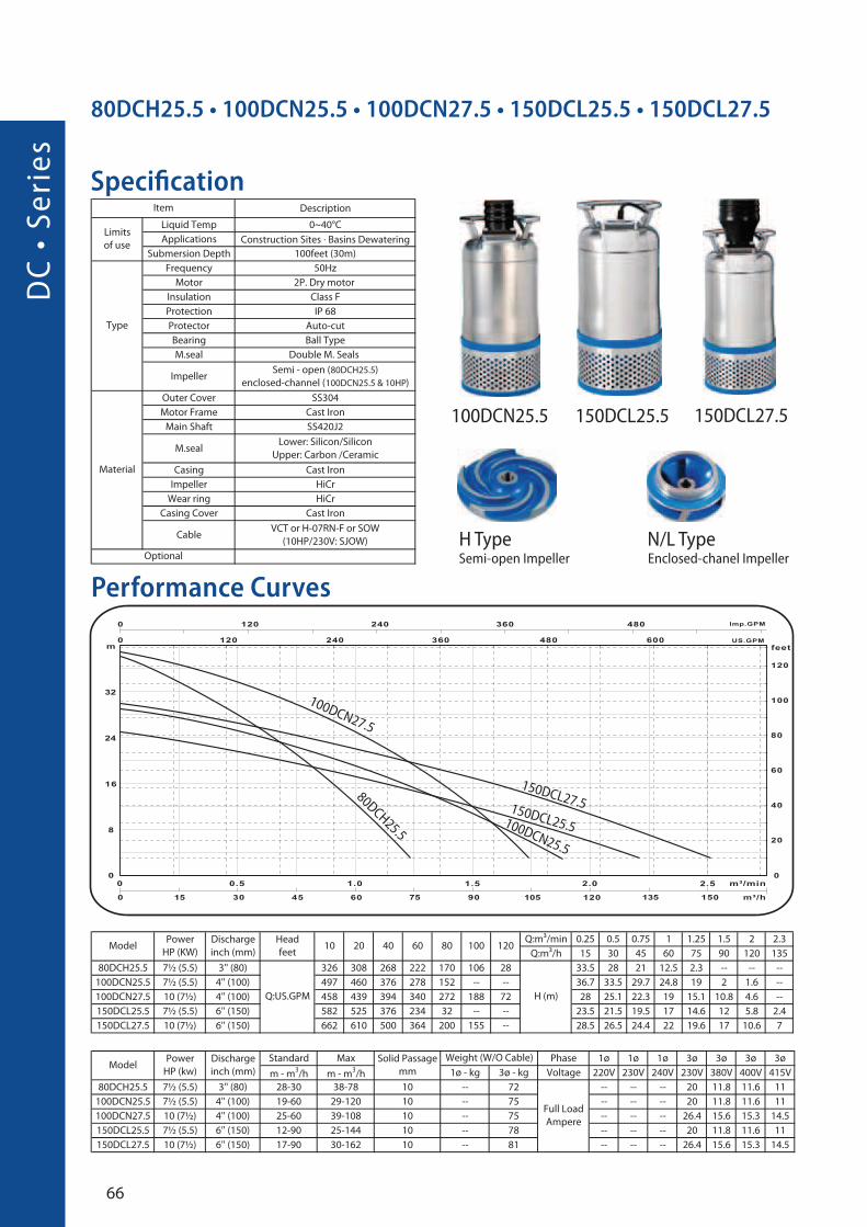
Specification
Performance Curves
80DCH25.5 • 100DCN25.5 • 100DCN27.5 • 150DCL25.5 • 150DCL27.5
�
150DCL25.5100DCN25.5
100DCN27.5
150DCL27.580DCH25.5
100DCN25.5 150DCL25.5
H Type Semi-open Impeller
N/L Type Enclosed-chanel Impeller
150DCL27.5
67
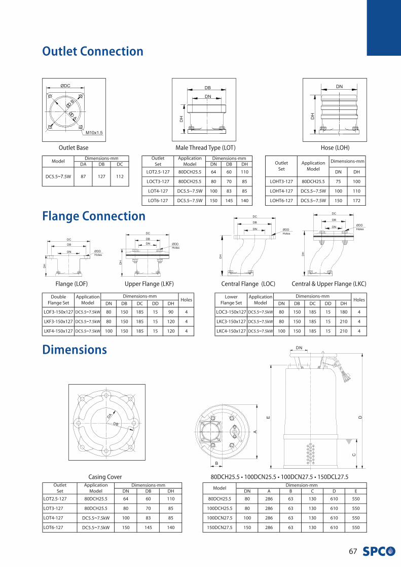
Outlet Connection
Dimensions
~ ~
~ ~
~ ~
~
~
Flange Connection
~7
Outlet Base Male Thread Type (LOT) Hose (LOH)
Flange (LOF) Central & Upper Flange (LKC)Upper Flange (LKF) Central Flange (LOC)
Casing Cover 80DCH25.5 • 100DCN25.5 • 100DCN27.5 • 150DCL27.5
DA
• S
eri
es
68
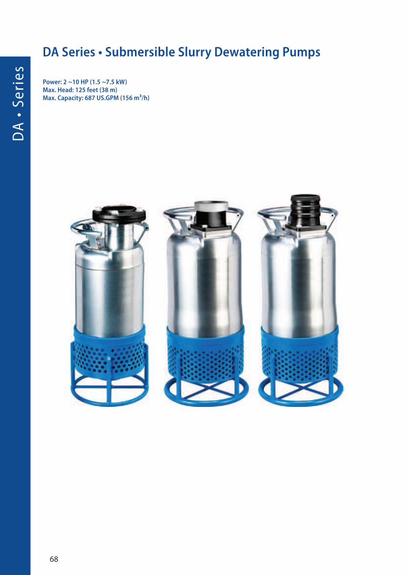
DA Series • Submersible Slurry Dewatering Pumps
Power: 2 ~10 HP (1.5 ~7.5 kW)Max. Head: 125 feet (38 m)Max. Capacity: 687 US.GPM (156 m³/h)
69
Application Specification
Features
Definition of model
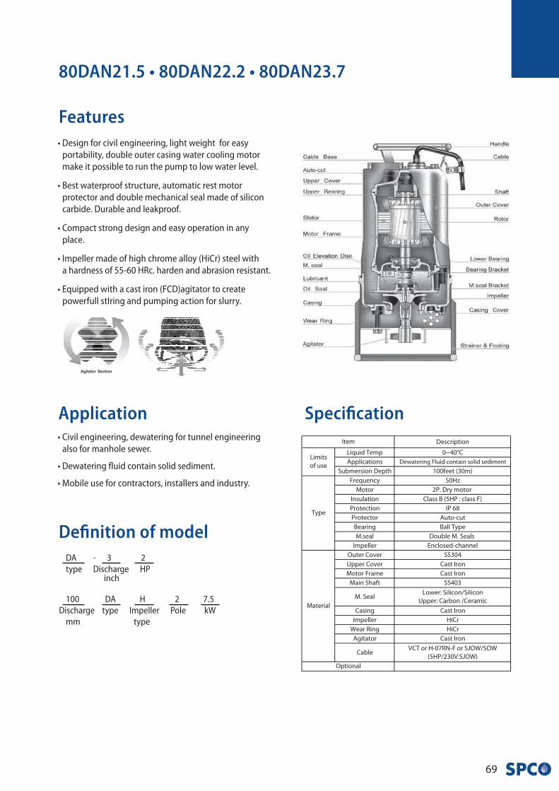
• Civil engineering, dewatering for tunnel engineering
also for manhole sewer.
• Dewatering fluid contain solid sediment.
• Mobile use for contractors, installers and industry.
80DAN21.5 • 80DAN22.2 • 80DAN23.7
• Design for civil engineering, light weight for easy
portability, double outer casing water cooling motor
make it possible to run the pump to low water level.
• Best waterproof structure, automatic rest motor
protector and double mechanical seal made of silicon
carbide. Durable and leakproof.
• Compact strong design and easy operation in any
place.
• Impeller made of high chrome alloy (HiCr) steel with
a hardness of 55-60 HRc. harden and abrasion resistant.
• Equipped with a cast iron (FCD)agitator to create
powerfull stIring and pumping action for slurry.
100 DA H 2 7.5
Discharge type Impeller Pole kW
mm type
DA - 3 2
type Discharge HP inch
DA
• S
eri
es
70
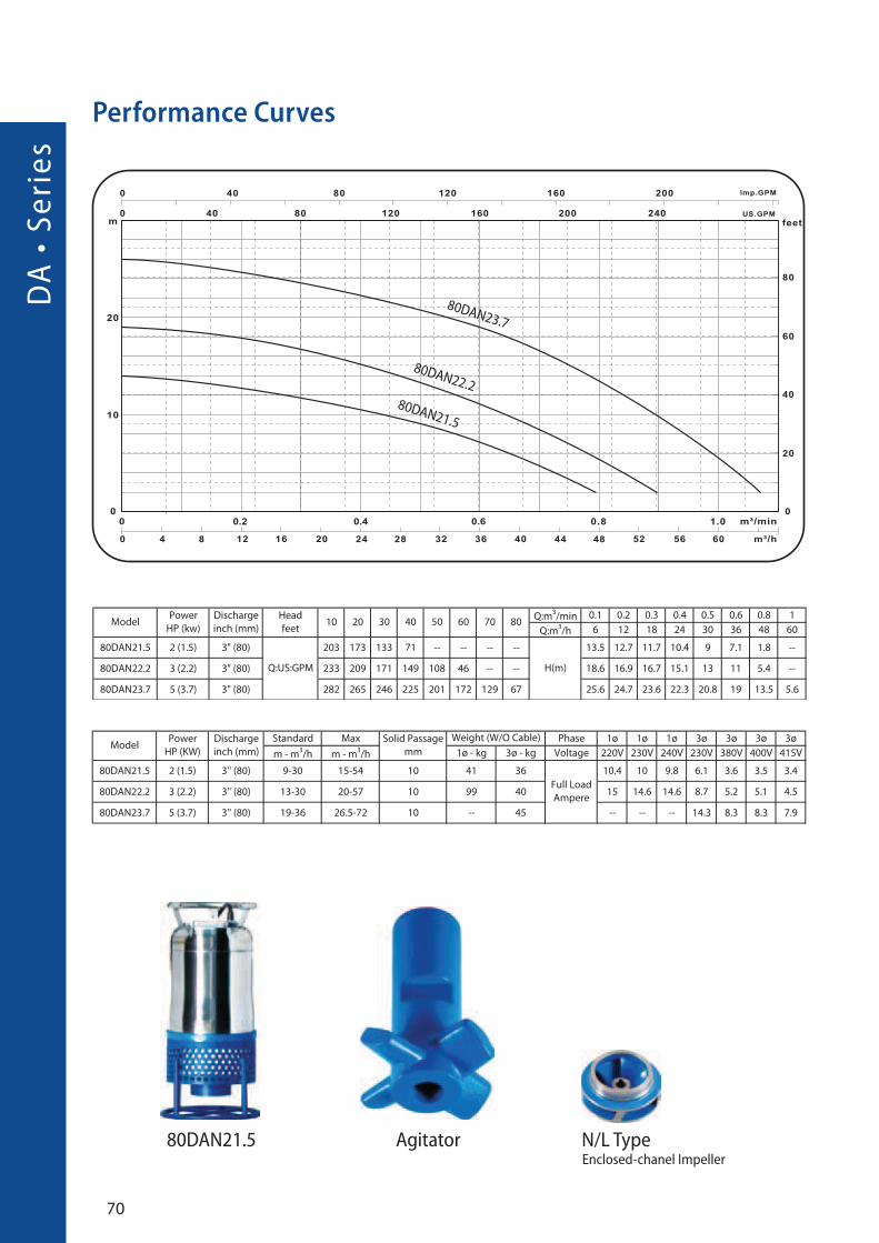
Performance Curves
80DAN23.7
80DAN22.2
80DAN21.5
80DAN21.5 Agitator N/L Type Enclosed-chanel Impeller

71
~3. ~3.
~3. ~3.
~ ~ ~
Flange Connection
Dimensions
Outlet Connection
Outlet Base Male Thread Type (LOT) Hose (LOH)
Flange (LOF) Central & Upper Flange (LKC)Upper Flange (LKF) Central Flange (LOC)
80DAN21.5 • 80DAN22.2 * 80DAN23.7
DA
• S
eri
es
72
Specification
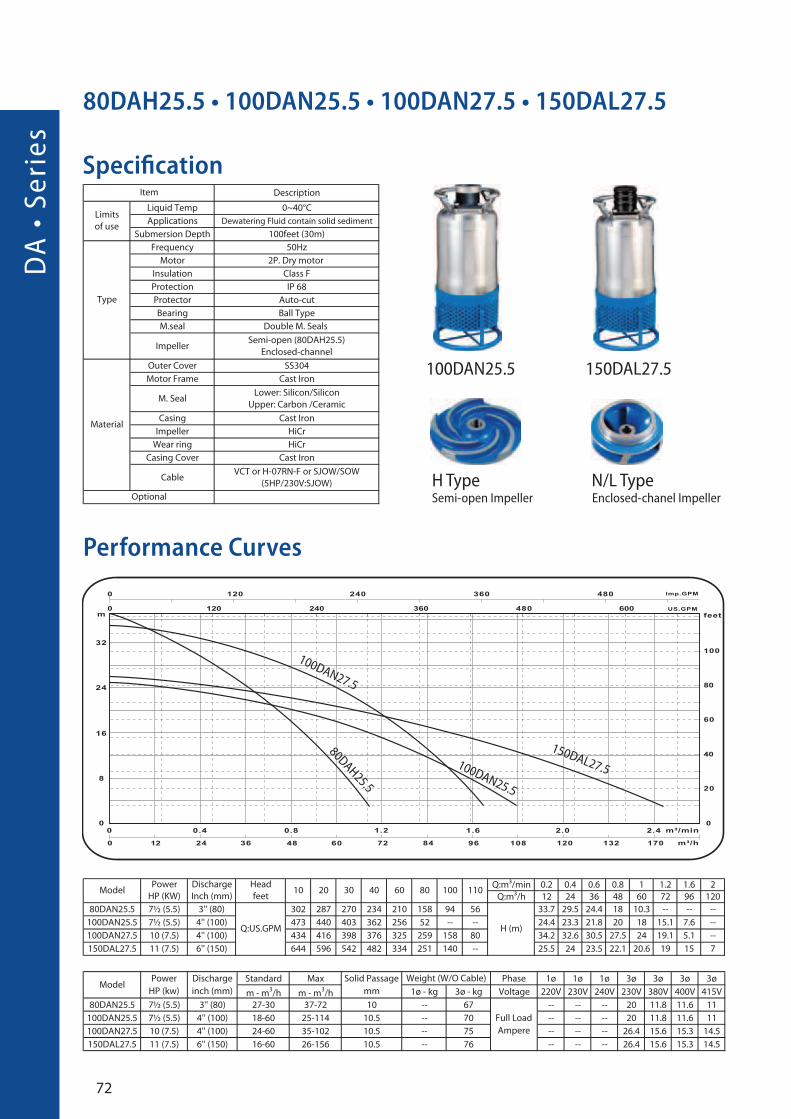
80DAH25.5 • 100DAN25.5 • 100DAN27.5 • 150DAL27.5
Performance Curves
150DAL27.5100DAN25.5
80DAH25.5
100DAN27.5
N/L Type Enclosed-chanel Impeller
100DAN25.5 150DAL27.5
H Type Semi-open Impeller

73
80DAH25.5 • 100DAN25.5 • 100DAN27.5 • 100DAL27.5
Outlet Connection
~7
Flange Connection
Dimensions
Outlet Base Male Thread Type (LOT) Hose (LOH)
Flange (LOF) Central & Upper Flange (LKC)Upper Flange (LKF) Central Flange (LOC)
~7.5 ~7.5
~7.5 ~7.5
~7.5 ~7.5

DW
• S
eri
es
74
DW Series • Submersible Dewatering Pumps
Power: 1/2 ~5 HP (1.1 ~3.7 kW)
Max. Head: 82 feet (25 m)Max. Capacity: 502 US.GPM (162 m³/h)
75
Application
Features
Definition of model
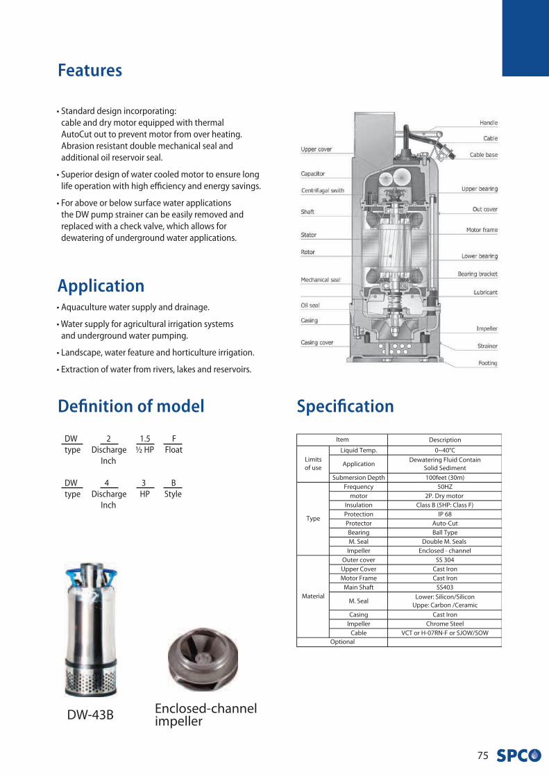
DW-43B Enclosed-channelimpeller
• Standard design incorporating:
cable and dry motor equipped with thermal
AutoCut out to prevent motor from over heating.
Abrasion resistant double mechanical seal and
additional oil reservoir seal.
• Superior design of water cooled motor to ensure long
life operation with high efficiency and energy savings.
• For above or below surface water applications
the DW pump strainer can be easily removed and
replaced with a check valve, which allows for
dewatering of underground water applications.
• Aquaculture water supply and drainage.
• Water supply for agricultural irrigation systems
and underground water pumping.
• Landscape, water feature and horticulture irrigation.
• Extraction of water from rivers, lakes and reservoirs.
Specification
DW 4 3 B
type Discharge
HP Style
Inch
DW 2 1.5 F
type Discharge ½ HP Float
Inch
DW
• S
eri
es
76
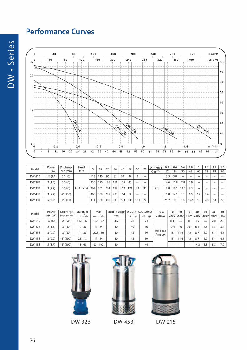
Performance Curves
DW-45BDW-43B
DW-33B
DW-32B
DW
-215
DW-215DW-45BDW-32B

77
Flange Connection
Dimensions
DW-32B • DW-33B • DW-43B • DW-45BCasing Cover
Double Flange Set Lower Flange
DW
• S
eri
es
78
½
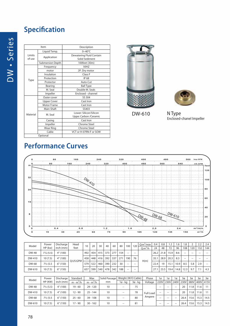
Performance Curves
Specification
DW-410
DW-610DW-68
DW-48
DW-610 N Type Enclosed-chanel Impeller
79
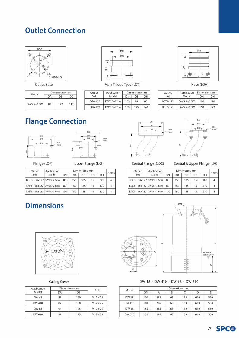
~7.5 ~7.5
~7.5 ~7.5
~7.5 ~7.5
Outlet Connection
Flange Connection
Dimensions
Outlet Base Male Thread Type (LOT) Hose (LOH)
Flange (LOF) Central & Upper Flange (LKC)Upper Flange (LKF) Central Flange (LOC)
DW-48 • DW-410 • DW-68 • DW-610Casing Cover
V •
Se
rie
s
80
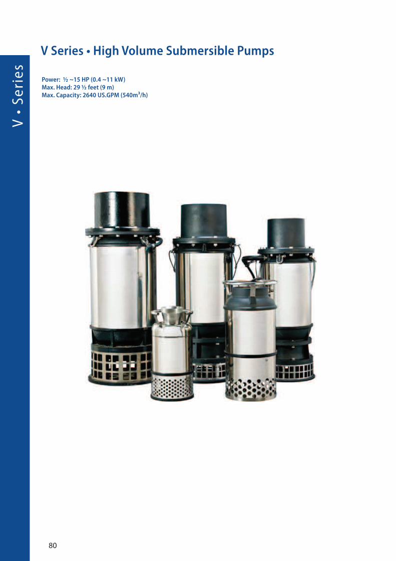
V Series • High Volume Submersible Pumps
Power: ½ ~15 HP (0.4 ~11 kW)Max. Head: 29 ½ feet (9 m)Max. Capacity: 2640 US.GPM (540m³/h)

81
Application
Features
V-41 • V-62 • V-63
Definition of model V - 4 - 1
Type Discharge HP
V - 300 A
Type Discharge Style
Inch
Inch
• Large flow capacities achieved with almost no
vibration or noise by use of Axial & Mix Flow design.
Giving easy operation and energy savings.
• Robust construction and compact design with a dry
motor, double mechanical seal and impeller flow
guide vane for high efficiency.
• Easy handling, energy saving and low maintenance.
• High efficiency motor directly connects to impeller to
achieve best energy saving.
• Pump manufactured with heavy duty housing, cable
leads are isolated by hardened epoxy for water
proofing, double mechanical seal.
• Achieved IP 68 (highest submersible water resistant
protection rating), keeps pumps dust free and water
proof to provide extended pump life and performance.
• Shaft and impeller are precisely balances for quiet and
long life performance.
• 3D computerized design of impeller and vanes
conductive design provide highest pump efficiency
and stability.
• Casted ALBC3 material (aluminum Bronze) impeller,
it has a greatabrasion and corrosion resistance.
• Aquaculture water pumping and drainage for large
volume water applications.
• Water supply for land scape, water features, cooling in
the power plant or drainage for industrial.
• Water extraction from rivers, lakes and reservoirs.
• Flood control or used for large volume dewatering.
Specification
V •
Se
rie
s
82
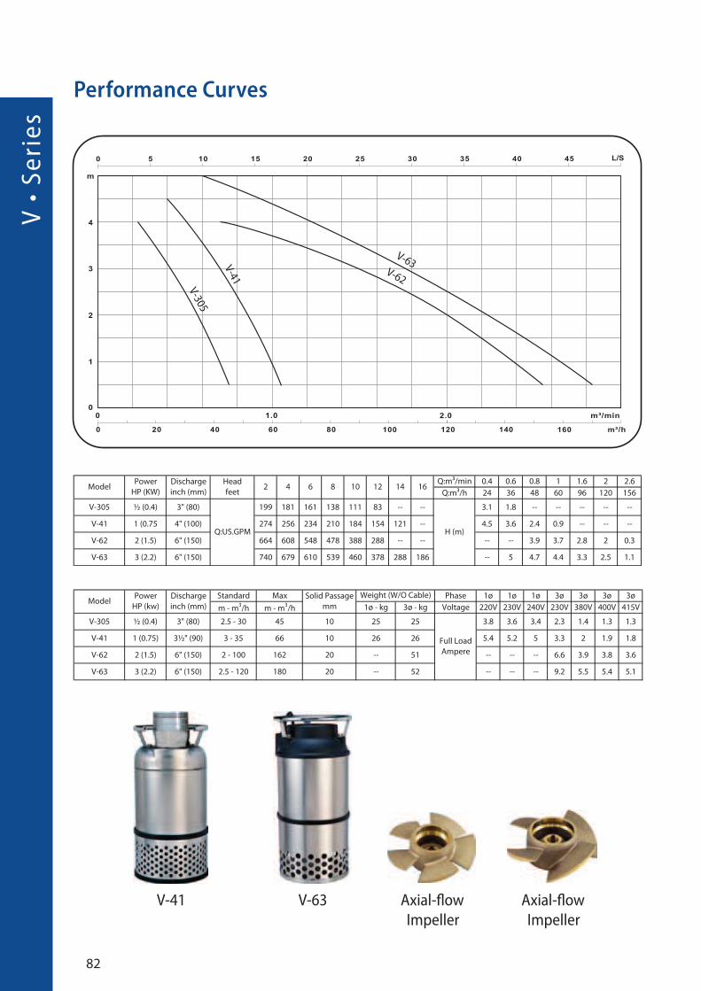
Performance Curves
V-41 V-63 Axial-flow
Impeller
Axial-flow
Impeller
V-63V-62
V-41
V-305
83
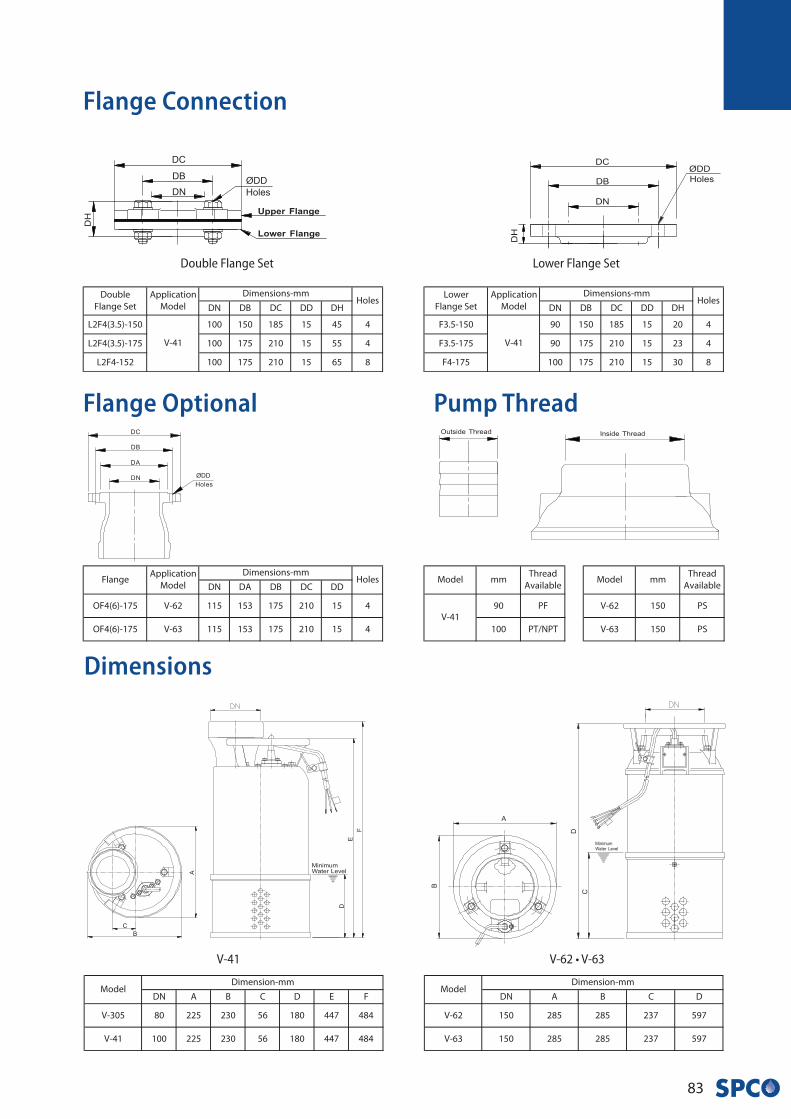
Dimensions
V-41 V-62 • V-63
Flange Connection
Double Flange Set Lower Flange Set
Flange Optional Pump Thread
V •
Se
rie
s
84
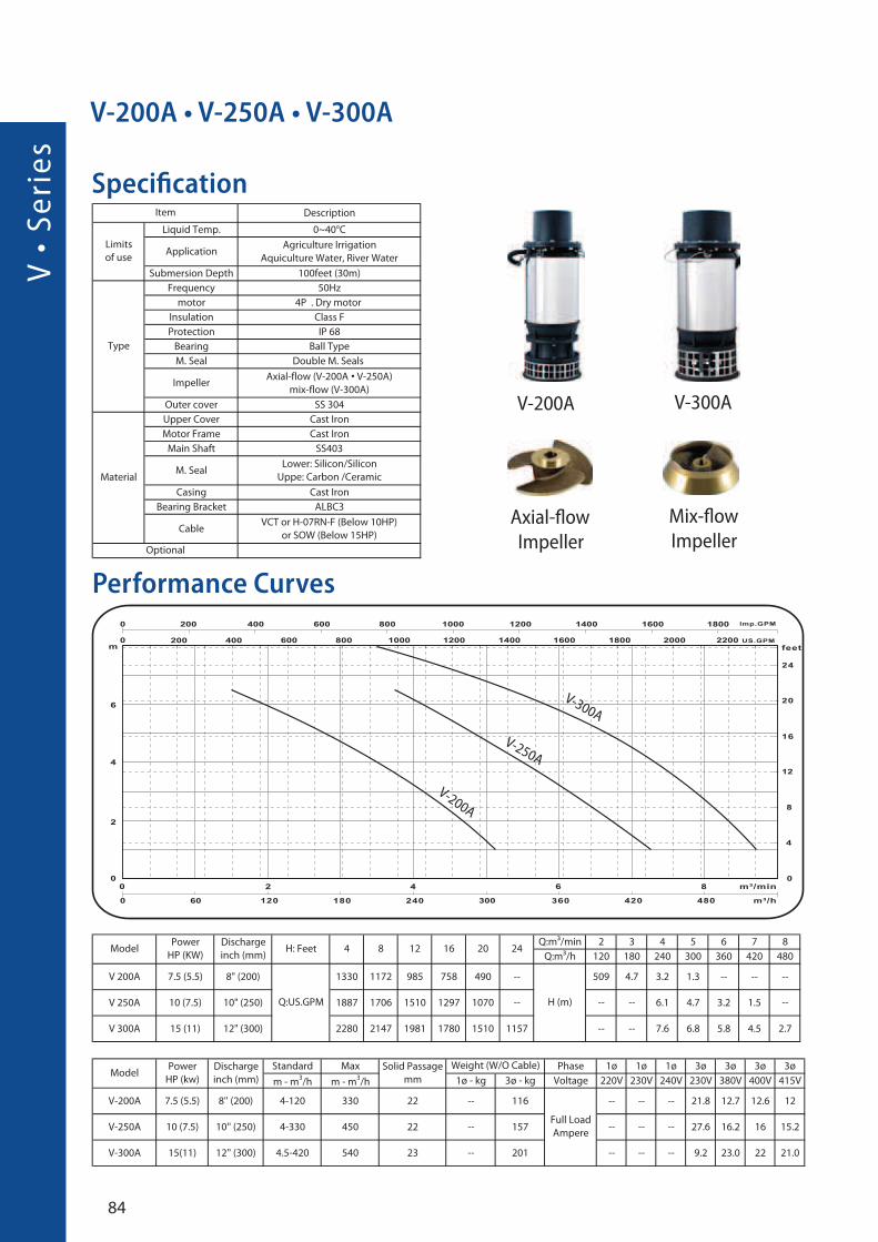
Specification
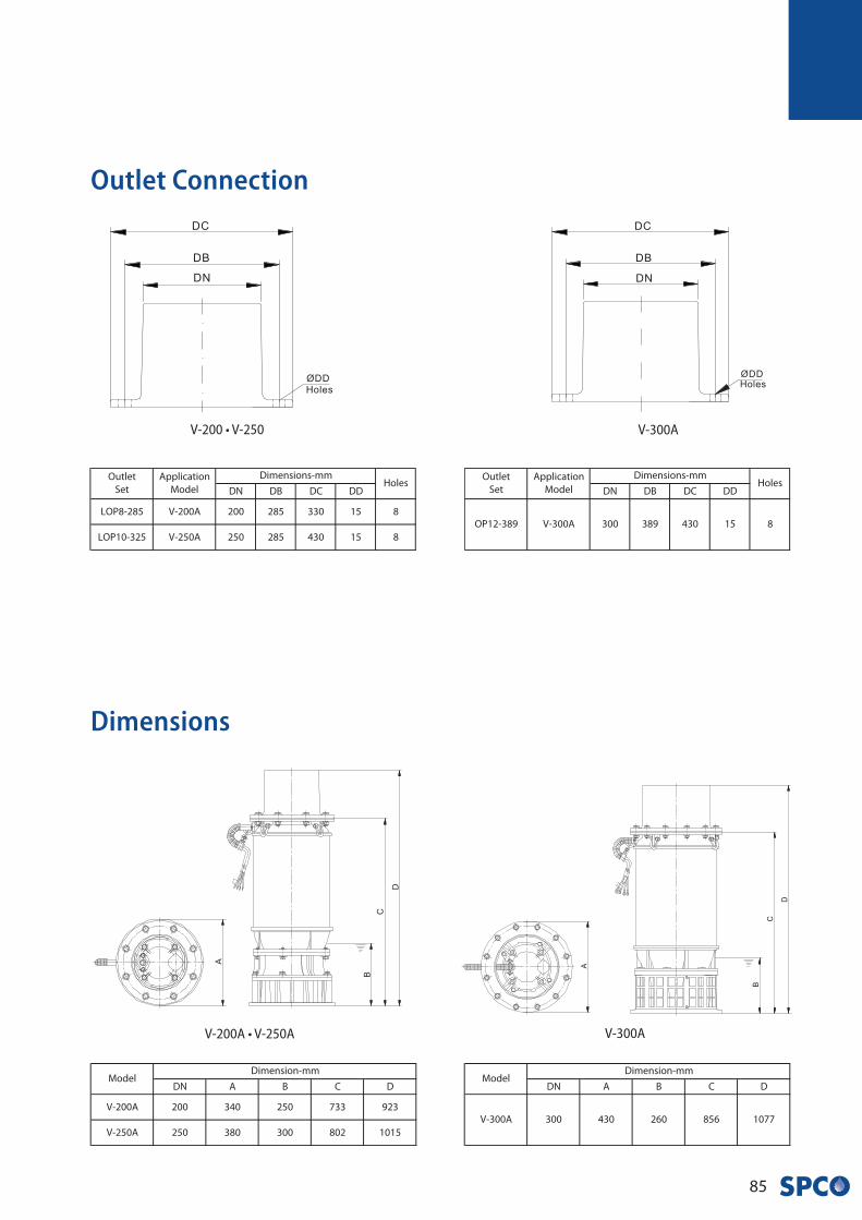
V-200A • V-250A • V-300A
Performance Curves
V-300A
V-250A
V-200A
V-200A V-300A
Axial-flow
Impeller
Mix-flow
Impeller
•
85
V-200 • V-250
Outlet Connection
V-200A • V-250A
V-300A
V-300A
Dimensions
LA
• S
eri
es
86
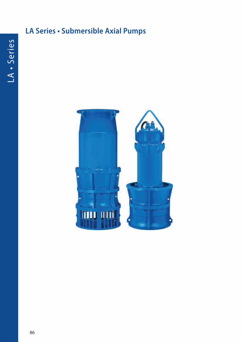
LA Series • Submersible Axial Pumps
87
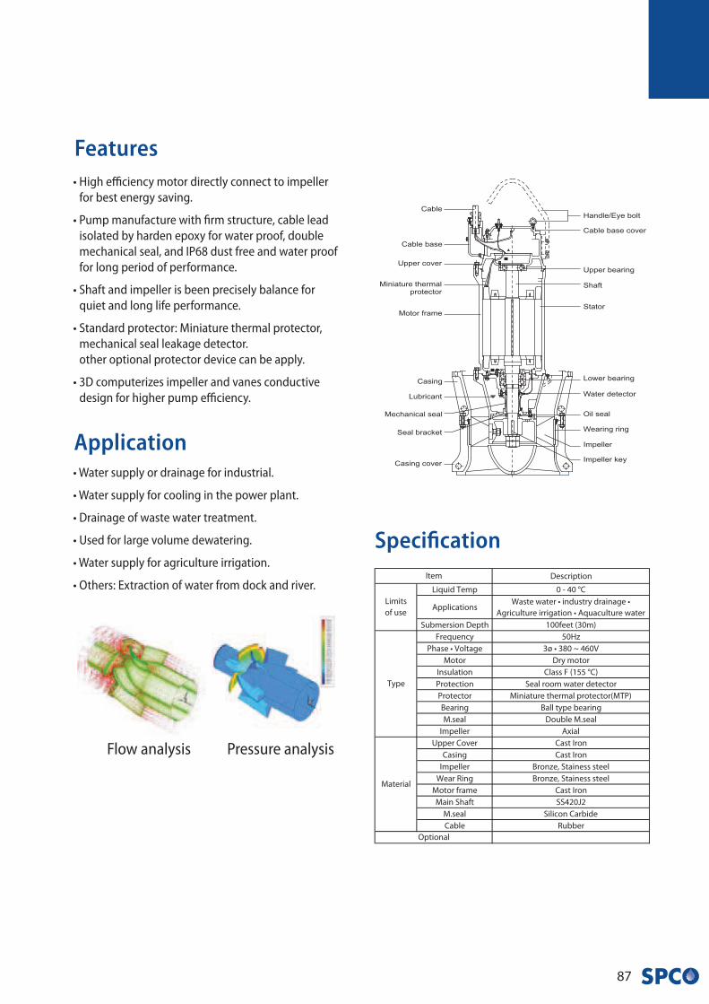
Application
Features• High efficiency motor directly connect to impeller
for best energy saving.
• Pump manufacture with firm structure, cable lead
isolated by harden epoxy for water proof, double
mechanical seal, and IP68 dust free and water proof
for long period of performance.
• Shaft and impeller is been precisely balance for
quiet and long life performance.
• Standard protector: Miniature thermal protector,
mechanical seal leakage detector.
other optional protector device can be apply.
• 3D computerizes impeller and vanes conductive
design for higher pump efficiency.
• Water supply or drainage for industrial.
• Water supply for cooling in the power plant.
• Drainage of waste water treatment.
• Used for large volume dewatering.
• Water supply for agriculture irrigation.
• Others: Extraction of water from dock and river.
Specification
Flow analysis Pressure analysis
LA
• S
eri
es
88
~ �
�
�
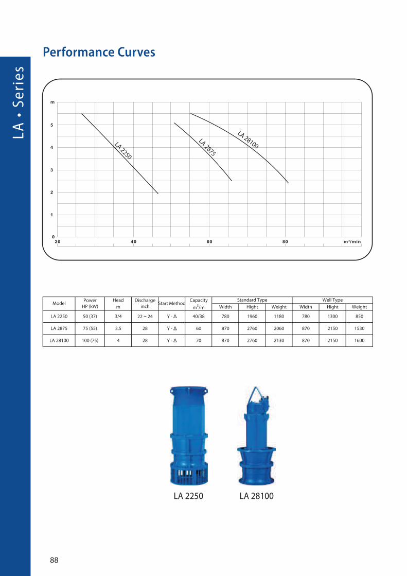
Performance Curves
LA 2250
LA 2875
LA 28100
LA 2250 LA 28100
89
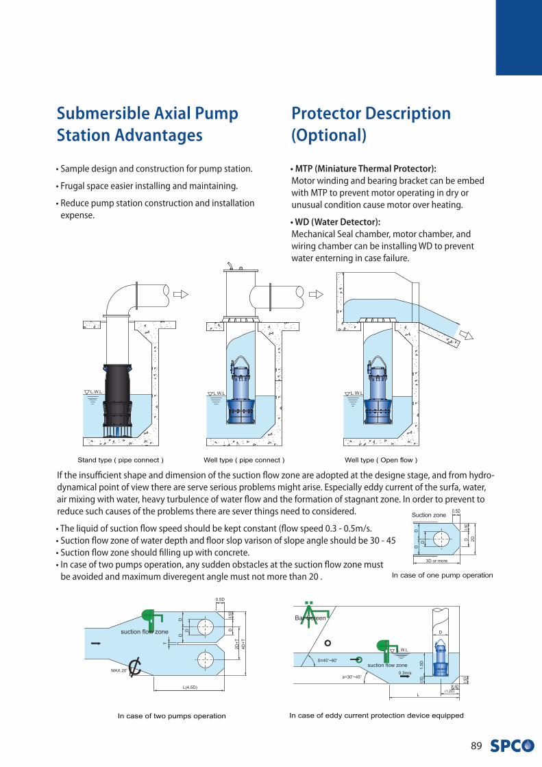
Submersible Axial Pump Station Advantages
• Sample design and construction for pump station.
• Frugal space easier installing and maintaining.
• Reduce pump station construction and installation
expense.
Protector Description (Optional)
• MTP (Miniature Thermal Protector): Motor winding and bearing bracket can be embed
with MTP to prevent motor operating in dry or
unusual condition cause motor over heating.
• WD (Water Detector): Mechanical Seal chamber, motor chamber, and
wiring chamber can be installing WD to prevent
water enterning in case failure.
If the insufficient shape and dimension of the suction flow zone are adopted at the designe stage, and from hydro-
dynamical point of view there are serve serious problems might arise. Especially eddy current of the surfa, water,
air mixing with water, heavy turbulence of water flow and the formation of stagnant zone. In order to prevent to
reduce such causes of the problems there are sever things need to considered.
• The liquid of suction flow speed should be kept constant (flow speed 0.3 - 0.5m/s.
• Suction flow zone of water depth and floor slop varison of slope angle should be 30 - 45
• Suction flow zone should filling up with concrete.
• In case of two pumps operation, any sudden obstacles at the suction flow zone must
be avoided and maximum diveregent angle must not more than 20 .


Swiss Pump Company AG
Moosweg 36
CH - 3645 Thun - Gwatt
Switzerland
Tel. +41 33 223 11 00
Fax +41 33 223 11 22
www.swisspump.com


