
Keeping the Customer First
NEW
Tooling system for unique function and wide variation
Tungaloy Report No. 413-E
Tooling system
BT Interface Series

2
P. 11ER Collet chuck systems
P. 28Power chuck endmill holder
P. 32Side lock endmill chuck holder
P. 36Adjustable drilling diameter holder
P. 45Hydraulic chucking system
P. 53Centering tooling system
P. 57Thermal shrinking holder
P. 72Electrical nut-clampingtorque control device
P. 34Side lock drill chuck holder
P. 38Modular tooling system
P. 52Balanceable collet chuck
P. 53Tapping attachment
P. 70Pull stud
P. 6Shell mill holder
Tooling system BT Interface

3
2.5xød
ød
0.003
P. 11
P. 28
P. 45
- Short overhang. - Applicable for standard ER collets.- Provides high gripping force and less runout with short overhang.- Balanced to G2.5, max. n: 20,000 min-1
- Symmetric design for high speed machining.
- Provides extremely high gripping force with only a small tightening torque.- High runout accuracy at 100mm. Over hang is 0.009 mm- High stiffness is achieved with the clamping mechanism that utilises the face contact between clamping nut and the face of the shank.- The highly rigid system prolongs tool life considerably.- Prevents interference with the work piece due to the slim design.- Preset screws available for all SC straight collets for positioning of the tool.- Produced from a special steel for vibration damping.- Sealed nut structure.- No axial drawback of the tool shank when chuck is tightened.
- High runout accuracy of less than 0.003 mm- Very low torque required to activate the clamping mechanism.- Easy tool overhang presetting by using an internal preset screw.- Symmetrical and balanced design for high speed machining of up to 15,000 min-1
- Very convenient and safe tool change on the machine.- Quick and easy operation for clamping and unclamping.
- Clean any grease and dirt from the chuck mounting hole and the tool shank. Insert the tool shank up to the stopper. Make sure that the minimum chucking length is maintained.- Do not attempt to clamp the chuck without a tool. It may break the clamping sleeve.- Tools with cylindrical shanks in accordance with DIN1835 and DIN6535 shape (HA) and B (HB) up to 20 mm diameters should be manufactured according to h6 tolerance and Ra = min 0.3 ground.- Tools with DIN6535 HE (whistle notch) shanks are not recommended. These may damage the chucking hole.
① Shallow tapered front end cone ② Clamping nut ③ Helical slot ④ Needle bearing ⑤ Front Seal ⑥ Ventilation bore (thread M4)⑦ Preset screw thread ⑧ Cap screw (for the preset screw)⑨ Preset screw⑩ Ground bore ⑪ Grip groove (for collet release)
Structure
Product introduction
Operating Instructions Clamping ScrewClamping Sleeve
Hydraulic OilAxial Adjustment Screw

4
Max
:D
+1.
3
Min
:D
-0.3
B
A
P. 64
P. 38
P. 38
P. 36
- Assembly structure: the taper goes inside the holder, achieving short overhang. - High rigidity and high runout due to the short overhang.- Taper and face make contact for maximum rigidity.- Balanced to G2.5, max. n: 20,000 min-1
- Quick changing: the taper shank and the holder connect in a quick half turn.
- Screw clamp head type promotes easy tool management.- Suitable for deep machining of metal molds due to the slim structure.- Provides wide machining variations with numerous combinations.- Provides high rigidity similar to integrated type holders.
- Provides high rigidity comparable to a solid part credit to the elastic deformation properties of the clamping system.- Reduces vibration by taper and face contact.- Easy clamping with only one screw.
- Enables the diameter of TungdrillTwisted (TDX) to be adjusted. Diameter adjusting range of -0.3 ~ +1.3 mm- With TungBore, standard TDX drills can cover the usage of special diameter drills.
* Adjustable range of diameter in TDX drill is different by each item. Therefore, please refer to the maximum offset value shown in TDX drill leaflet.
① Fix the TDX drill with the clamping screw.② Adjust the screw "A". Preset should be made on a pre-setter to -0.2 mm from the required diameter. Tighten the clamp screw "B".③ On the machine, make a test cut.④ Measure the bore diameter.⑤ Make the adjustment to the desired diameter on the machine with dial indicator or on the pre-setter.⑥ Loosen the clamping screw. ⑦ Adjust to the required diameter ("Desired diameter" - "Measured diameter") / 2 = "Adjusted amount"⑧ Tighten the clamping screw.
Operating Instructions
A: Clamp screwB: Adjust screw

5
10 gr x mm, 100° 27 gr x mm, 285°
80
20
0
10
10
0
20
30
280
20
20 30 40
10
YES
YES
YES
YES
NO
NO
NO
P. 53
P. 52
P. 53
- Easy to adjust dynamic balance. It is possible to correct it by simply turning the ring and adjusting the unbalanced amount measured with the balance measuring instrument.
set example
Do not use Weldon shanks.For extremely high balance levels, tools with even number of flutes are recommended.
Set all rings for “0”.
Move both golden rings 5° to the instructed direction.
Without changing the instructed angle, decrease the golden ring’s correction amount according to the measurement.
Without changing the instructed angle, increase the golden ring’s correction amount according to the measurement.
Once again, measure the amount of unbalance
Set the angle and the amount of correction according to the measurement
Measure the amount of unbalance.
Within the accuracy
Within ±180°untill 3gr x mm
Within ±20°untill 3gr x mm
With 20°~ 90°untill 1gr x mm
Start
END
Coolant Hole
Rear Seal
Drive Shaft
Front SealRear BearingSpring PistonFront Bearing
O-ringSeal Gasket
Bearing Adjustment NutFlat For SupportingWrench
ER Nut
Don't tighten the ER Nut without using supporting wrench.
- Provides high accuracy reaming and extended tool life due to the unique floating mechanism.- The radial self-floating mechanism corrects the misalignment between reamer and work piece hole.
- Contains the mechanisms of tension, compression, and floating. - No tap collets necessary.- Compact geometry with high rigidity.
Attention 1
Attention 2
Radial Float
- Corrects unbalance up to: Collet Chuck 61 gr. x mm Top Nut 54 gr. x mm- Simple balancing procedure on all types of balancing machines.- An existing collet chuck can be changed to the balance holder by simply exchanging the nut.

670 9 9
L
øD
ML2 L1
øD1
G
58-60 HRC ➚ A 0.005 N5A
1 2
BT-SEM
12
BT MAS 403 Form AISO 3937
øD1 L1 øD L L2 G M BT30SEM16X50 (*) � 16 17 38 50 28 M12 M8 BT30SEM22X50 (*) � 22 19 47 50 18 M12 M10 BT30SEM25.4-45V1 (*) � 25.4 22 50 45 18 M12 M12 BT30SEM27X50 (*) 27 21 58 50 18 M12 M12 BT40SEM16X60 (*) � 16 17 38 60 33 M16 M8 BT40SEM16X120 (*) 16 17 38 120 93 M16 M8 BT40SEM22X60 (*) � 22 19 47 60 33 M16 M10 BT40SEM22X120 (*) 22 19 47 120 93 M16 M10 BT40SEM25.4X45V1 (*) � 25.4 22 50 45 18 M16 M12 BT40SEM27X45 (*) 27 21 58 45 18 M16 M12 BT40SEM27X105 (*) 27 21 58 105 78 M16 M12 BT40SEM31.75X45V1 (*) � 31.75 30 64 45 20 M16 M16 BT40SEM31.75X75V1 (*) � 31.75 30 64 75 48 M16 M16 BT40SEM32X60 (*) 32 24 65 60 23 M16 M16 BT40SEM32X75 (*) 32 24 65 75 36 M16 M16 BT40SEM40X60 (*) 32 27 82 60 23 M16 M20 BT40SEM40X75 (*) 32 27 82 75 38 M16 M20 BT50SEM16X75 (*) 16 17 38 75 37 M24 M8 BT50SEM16X120 (*) 16 17 38 120 82 M24 M8 BT50SEM22X50X220 22 19 50 220 182 M24 M10 BT50SEM22X64X320 22 19 64 320 282 M24 M10 BT50SEM22X75 (*) � 22 19 47 75 37 M24 M10 BT50SEM22X120 (*) 22 19 47 120 82 M24 M10 BT50SEM25.4x90V1 (*) � 25.4 22 50 90 52 M24 M12 BT50SEM27X60 (*) 27 21 58 60 22 M24 M12 BT50SEM27X105 (*) 27 21 58 105 67 M24 M12 BT50SEM31.75X75V1 (*) � 31.75 30 75 64 26 M24 M16 BT50SEM32X48 (*) 32 24 66 48 10 M24 M16 BT50SEM32X75 (*) 32 24 66 75 37 M24 M16 BT50SEM38.1X75V1 (*) � 38.1 34 80 75 37 M24 M20 BT50SEM40X48 (*) 40 27 82 48 10 M24 M20 BT50SEM40X75 (*) 40 27 82 75 37 M24 M20 BT50SEM50.8X75V1 (*) � 50.8 36 100 75 37 M24 M24
☞Pull Stud Lock Screw
PageWrench
(*): Availeable center trough by lock screw with coolant hole. TMBA-**H, CM****H (option)Tungaloy mills with coolant hole is attached screw with coolant hole.Wrench is not included.
Cat. No. Dimensions (mm)BT-SEM Shell Mill Holder
AT3 Taper
Stock
Shell Mill Holder

770 9 9
L
L2 L1
G
øD1 øD
58-60 HRC ➚ A 0.005 N5A
1 2
12
BT MAS 403 Form A/BISO 3937
BT-SEM-C
øD1 øD L L1 L2 G MBT40SEM16X60C 16 38 60 33 17 M16 M8BT40SEM16X100C 16 38 100 73 17 M16 M8BT40SEM22X60C � 22 47 60 33 19 M16 M10BT40SEM22X100C 22 47 100 73 19 M16 M10BT40SEM27X45C � 27 58 45 18 21 M16 M12BT40SEM27X100C 27 58 100 73 21 M16 M12BT40SEM32X60C 32 66 60 33 24 M16 M16BT50SEM16X75C � 16 38 75 37 17 M24 M8BT50SEM16X100C 16 38 100 62 17 M24 M8BT50SEM22X75C 22 47 75 37 19 M24 M10BT50SEM22X100C 22 47 100 62 19 M24 M10BT50SEM22X48X220C 22 48 220 182 19 M24 M10BT50SEM22X61X320C 22 61 320 282 19 M24 M10BT50SEM25.4X60C � 25.4 50 60 22 22 M24 M12BT50SEM27X60C � 27 58 60 22 21 M24 M12BT50SEM27X100C 27 58 100 62 21 M24 M12BT50SEM27X61X320C 27 61 320 282 21 M24 M12BT50SEM32X75C 32 66 75 37 24 M24 M16BT50SEM32X100C 32 66 100 62 24 M24 M16BT50SEM32X78X390C 32 78 390 352 24 M24 M16
☞Lock ScrewPull Stud Wrench
BT-SEM-C Extra Long Shell Mill Holder with Coolant Hole
If the “B type” option is required, the plug screw must be removed from the flange cooling hole (use a 2 mm hex key).Wrench is not included.
AT3 Taper
Shell Mill Holder
Cat. No. StockDimensions (mm)
Page

870 9 9
G
øD2G2
LL2 L1
øDøD1
G1
1 2
BT-FM
øD1 L1 L L2 øD øD2 G1 G2 G
BT40FM40 40 27 60 22 88 66.7 M20 M12 M16BT50FM40 40 27 50 12 88 66.7 M20 M12 M24BT50FM60 60 38 88 40 128 101.6 - M16 M24
øD1 L1 L L2 øD øD2 G1 G2 G
BT50-FMA47.625-75 � 47.625 38 75 - 128.6 101.6 - M16 M24
1 2BT MAS 403 Form A DIN6357
☞Pull Stud Lock Screw Wrench
Face Mill Holder
BT-FM Face Mill Holder - MetricDimensions (mm)
Dimensions (mm)Cat. No.
Cat. No.
BT-FM Face Mill Holder - Inch
Stock
Stock
Page
Wrench is not included.

9
øD1
K
L
G øD1
K
L
G
A
A SCREW-SEM
H
L
G øD1 K LM8CLAMPSCREWSEM16 � 16 M8 20 6 16M10CLAMPSCREWSEM22 � 22 M10 28 7 18M12CLAMPSCREWSEM27 � 25.4, 27 M12 35 8 22M16CLAMPSCREWSEM32 � 31.75, 32 M16 42 9 26M20CLAMPSCREWSEM40 � 38.1, 40 M20 52 10 30M24CLAMPSCREWSEM50 � 50, 50.8 M24 63 12 36
H L
WRENCHM8SEMC16 � 16 M8 20 180WRENCHM10SEMC22 � 22 M10 25 200WRENCHM12SEMC27 � 25.4, 27 M12 32 225WRENCHM16SEMC32 � 31.75, 32 M16 36 250WRENCHM20SEMC40 � 38.1, 40 M20 40 280WRENCHM24SEMC50 � 50, 50.8 M24 50 315
G øD1 K L
TMBA-M12H � 25.4, 27 M12 33 8.5 26TMBA-M16H � 31.75, 32 M16 40 10 32.5TMBA-M20H � 38.1, 40 M20 50 10 34TMBA-M24H � 50, 50.8 M24 65 14 43
a øb c d fCM8×30H � M8×1.25 13 36 30 5CM10×30H � M10×1.5 16 38 30 6CM12×30H � M12×1.75 18 40 30 8CM16×40H � M16×2 24 54 40 10
WRENCH SEMC
SCREW-SEMB
B
øb
cfd
a
CM**H
SCREW-SEM Lock Screw for Shell Mill Holder
Cat. No.
Shell Mill Holder • Lock Screw • Wrench
Screw Size
(Option)Wrench DIN 6368 for COMBI Shell End mill Holder
Cat. No.
Cat. No.
Cat. No.
Stock Inner diameter of cutter body ø
Inner diameter of cutter body ø
Inner diameter of cutter body ø
Stock
Stock
Stock
TMBA-M**H Lock Screw with coolant slot for Shell Mill Holder
CM**H Lock Screw with coolant slot for Shell Mill Holder
Dimensions (mm)
Dimensions (mm)
Dimensions (mm)
Dimensions (mm)

10
LL2 L1
øDøD1
L3
G
58-60 HRC N5A ➚ A 0.005
1 2
12
BT MAS 403 Form ADIN6358
BT-SEMC
øD1øD 3 B
L
H H
DRIVING RING SEMC
øD1 øD3 L B H16D.RINGSEMC � 16 32 10 8 5.022D.RINGSEMC � 22 40 12 10 6.027D.RINGSEMC � 27 48 12 12 6.332D.RINGSEMC � 32 58 14 14 7.040D.RINGSEMC � 40 70 14 16 8.050D.RINGSEMC � 50 90 16 18 9.0
øD1 L1 øD L L2 L3 GBT40SEMC16X50 16 17 32 50 23 27 M16BT40SEMC16X100 16 17 32 100 73 27 M16BT40SEMC22X53 22 19 40 53 26 31 M16BT40SEMC22X100 22 19 40 100 73 31 M16BT40SEMC27X55 27 21 48 55 28 33 M16BT40SEMC27X100 27 21 48 100 73 33 M16BT40SEMC32X60 32 24 58 60 33 38 M16BT40SEMC32X100 32 24 58 100 73 38 M16BT40SEMC40X80 40 27 70 80 53 41 M16BT50SEMC16X100 16 17 32 100 62 27 M24BT50SEMC16X150 16 17 32 150 112 27 M24BT50SEMC22X68 22 19 40 68 30 31 M24BT50SEMC22X100 22 19 40 100 62 31 M24BT50SEMC22X150 22 19 40 150 112 31 M24BT50SEMC27X78 27 21 48 78 40 33 M24BT50SEMC27X100 27 21 48 100 62 33 M24BT50SEMC27X150 27 21 48 150 112 33 M24BT50SEMC32X78 32 24 58 78 40 38 M24BT50SEMC32X100 32 24 58 100 62 38 M24BT50SEMC32X150 32 24 58 150 112 38 M24BT50SEMC40X78 40 27 70 78 40 41 M24BT50SEMC40X100 40 27 70 100 62 41 M24BT50SEMC40X150 40 27 70 150 112 41 M24BT50SEMC50X79 50 30 90 79 41 46 M24BT50SEMC50X150 50 30 90 150 112 46 M24
70 9 9☞
BT-SEMC COMBI – Shell Mill Holder (Combination type)
Cat. No.
AT3 Taper
Shell Mill Holder / Side Mill Holder
Driving Ring DIN 6366/1 for COMBI Shell and Mill HolderCat. No.
Accessories • Wrench for Shell Mill Holder
Stock
Stock
Dimensions (mm)
Dimensions (mm)
Wrench is not included.
Pull Stud Lock Screw Wrench
Page

11
BT MAS-403
ST Straight Shank
MT Morse Taper
ER-SPR (ER Spring Collet)
ER-SEAL (ER SEAL Collet for Internal coolant)
ER-SEAL JET2(ER SEAL Collet for External coolant)
ER-SRK(ER Collet with SHRINK Holder)
ER32 GTIN(ER Collet with Tapping Holder)
ER32 ODP(ER Collet with Indexable Modular System)
Collet OptionsShanks
ER Collet Chucking System

12
70 26 27 16 27 23
øD1
L
øD
L2G
J
L1
A 58-60 HRC ➚ A 0.003 N5
1
L L1 L2 øD øD1 J GBT30ER16X70 (1) � 0.5-10 70 48 - 28 - M10 M12BT30ER20X70 (1) � 1-13 70 48 - 34 - M12 M12BT40ER11X100M (2) � 0.5-7 100 73 - 16 - M6 M16BT40ER16X70 0.5-10 70 43 - 28 - M12 M16BT40ER16X100 � 0.5-10 100 73 - 28 - M12 M16BT40ER16X150 � 0.5-10 150 123 110 28 40 M12 M16BT40ER16X200 � 0.5-10 200 173 85 28 40 M10 M16BT40ER20X70 1-13 70 43 - 34 - M12 M16BT40ER20X100 � 1-13 100 73 - 34 - M12 M16BT40ER20X120 � 1-13 120 93 - 34 - M12 M16BT40ER20X150 � 1-13 150 123 - 34 - M12 M16BT50ER16X100 (1) 0.5-10 100 62 - 28 - M12 M24BT50ER16X125 (1) � 0.5-10 125 87 - 28 - M12 M24BT50ER16X150 (1) � 0.5-10 150 112 - 28 - M12 M24BT50ER16X200 (1) � 0.5-10 200 162 85 28 40 M10 M24BT50ER20X100 (1) 1-13 100 62 - 34 - M12 M24BT50ER20X125 (1) � 1-13 125 87 - 34 - M12 M24BT50ER20X150 (1) � 1-13 150 112 - 34 - M12 M24BT50ER20X200 (1) � 1-13 200 162 85 34 50 M12 M24
BT-ER16/20
2
G2.520,000 min-1
12
BT MAS 403 Form A/BDIN6499
☞Pull Stud Nut Wrench ER Collet Preset Screw User Guide
Add B for coolant through the flange.(1) Balanced to G6.3 at max. n: 12,000 min-1
(2) ER11 MINI Collet Chuck Spec.Wrench is not included.
Range
AT3 Taper
Cat. No.
Collet Chuck Holder
Stock Dimensions (mm)BT-ER16/20 ER Collet Chuck Holder
Page

13
70 26 27 16 27 23
L
øD
L1
G
G1
J
øD1
L
øD
L2
JG
L1
A 58-60 HRC ➚ A 0.003 N5
A
B
1 2 1 2
B BT-ER-SHORTA BT-ER
L L1 L2 øD øD1 J GBT30ER25X60 (1) � 1-16 60 38 - 42 - M16 M12BT30ER32X60 (1) � 2-20 60 38 - 50 - M18x1.5 M12BT40ER25X60 1-16 60 33 - 42 - M16 M16BT40ER25X100 � 1-16 100 73 - 42 - M16 M16BT40ER25X150 � 1-16 150 123 - 42 - M16 M16BT40ER32X60 2-20 60 33 - 50 - M22X1.5 M16BT40ER32X100 � 2-20 100 73 - 50 - M22X1.5 M16BT40ER32X120 � 2-20 120 93 - 50 - M22X1.5 M16BT40ER32X150 � 2-20 150 123 - 50 - M22X1.5 M16BT40ER40X80 3-26 80 53 - 63 - M28X1.5 M16BT40ER40X100 3-26 100 73 - 63 - M28X1.5 M16BT40ER40X150 3-26 150 123 - 63 - M28X1.5 M16BT40ER50X90 10-34 90 63 - 78 - M28X1.5 M16BT50ER25X100 (1) 1-16 100 62 - 42 - M16 M24BT50ER25X150 (1) � 1-16 150 112 - 42 - M16 M24BT50ER25X200 (1) � 1-16 200 162 87 42 55 M16 M24BT50ER32X100 (1) 2-20 100 62 - 50 - M22X1.5 M24BT50ER32X125 (1) � 2-20 125 87 - 34 - M22X1.5 M24BT50ER32X150 (1) � 2-20 150 112 - 50 - M22X1.5 M24BT50ER32X200 (1) � 2-20 200 162 88 50 63 M22X1.5 M24BT50ER40X100 (1) 3-26 100 62 - 63 - M28X1.5 M24BT50ER40X150 (1) 3-26 150 112 - 63 - M28X1.5 M24BT50ER40X200 (1) 3-26 200 162 - 63 - M28X1.5 M24BT50ER50X100 (1) 10-34 100 62 - 78 - M36X1.5 M24BT50ER50X150 (1) 10-34 150 112 - 78 - M36X1.5 M24
12
BT MAS 403 Form A/BDIN6499
12
BT MAS 403 Form A/BDIN6499 ER-SHORT
G2.520,000 min-1
G2.520,000 min-1
L L1 øD J G G1
BT30ER20SHORT � 1-13 27.2 5.2 25 M12 M12 M25x1.5BT40ER32SHORT � 2-20 36.5 9.5 40 M12 M16 M40x1.5BT40ER40SHORT 3-26 46.5 9.5 50 M16 M16 M50x1.5BT50ER32SHORT � 2-20 47.5 9.5 40 M22x1.5 M24 M40x1.5BT50ER40SHORT 3-26 47.5 9.5 50 M28x1.5 M24 M50x1.5
☞Pull Stud Nut Wrench ER Collet Preset Screw User Guide
Range
Range
BT-ER ER Collet Chuck Holder
BT-ER-SHORT Short ER Collet Chuck Holder
Add B for coolant through the flange.Wrench is not included.
Add B for coolant through the flange.(1) Balanced to G6.3 at max. n: 12,000 min-1
Wrench is not included.
AT3 Taper
Collet Chuck Holder •
Dimensions (mm)
Dimensions (mm)
Cat. No. Stock
Cat. No. Stock
Page

14
16 26 27 27 23
øD1
L1 L
J
øD
T
58-60 HRCA ➚ A 0.005 N5
øD1
L1 L
J
øD
A - A
T
A
A
A 58-60 HRC ➚ A 0.005 N5
12
1 2
1 2
12
ST-ER-M / MF
ST-ER
L1 L J øD øD1 TST16X50ER11F 0.5-7 50 18.5 M8 19 16 13ST20X50ER11F 0.5-7 50 18.5 M10 19 20 17ST20X100ER11 0.5-7 100 18.5 M10 19 20 17ST20X150ER11 0.5-7 150 18.5 M10 19 20 17ST20X50ER16F 0.5-10 50 32.3 M12 28 20 19ST20X100ER16 0.5-10 100 30.0 M12 28 20 19ST20X150ER16 0.5-10 150 30.0 M12 28 20 19ST20X50ER20F 1-13 50 42.5 M12 34 20 22ST25X100ER20 1-13 100 36.0 M16 34 25 22ST25X100ER20F 1-13 100 36.0 M16 34 25 22ST25X150ER20 1-13 150 36.0 M16 34 25 22
L1 L J øD øD1 TST12X80ER11M 0.5-7 80 26.5 - 16 12 11ST16X50ER11MF 0.5-7 50 18.5 M8 16 16 13ST16X100ER11M 0.5-7 100 18.5 M8 16 16 13ST16X150ER11M 0.5-7 150 18.5 M8 16 16 13ST12X80ER16M 0.5-10 80 36.5 M12 22 12 17ST20X100ER16M 0.5-10 100 25.0 M12 22 20 17ST20X150ER16M 0.5-10 150 25.0 M12 22 20 17ST20X100ER20M 1-13 100 40.0 M12 28 20 21ST20X150ER20M 1-13 150 40.0 M12 28 20 21
☞ER Collet Nut Wrench Preset Screw User Guide
ST-ER-M/MF Mini ER Collet Chuck Holder
F indicates a flat on the shank.Wrench is not included.
F indicates a flat on the shank.Wrench is not included.
ST-ER ER Collet Chuck Holder
Straight ShankDIN6499
Straight ShankDIN6499
Collet Chuck • Straight Shank
Cat. No. Stock
Cat. No. Stock
Range
Range
Dimensions (mm)
Dimensions (mm)
Page

15
16 26 27 27 23
L1 L
øD1 h6
J
T
øD
J
øD1
L L1
T
øD
58-60 HRCA ➚ A 0.005 N5
A
B
1 2
12
1 2
B ST-ER-MFA ST-ER
L1 L J øD øD1 TST20X50ER25F 1-16 50 46 M12 42 20 28ST20X100ER25 1-16 100 46 M12 42 20 28ST20X50ER32F 2-20 50 54 M12 50 20 36ST20X100ER32 2-20 100 54 M12 50 20 36ST25X50ER25F 1-16 50 46 M16 42 25 28ST25X100ER25 1-16 100 46 M16 42 25 28ST25X50ER32F 2-20 50 52 M16x2 50 25 36ST25X50ER40F 3-26 50 60 M16x2 63 25 45ST30X50ER32F 2-20 50 52 M18x1.5 50 30 36ST30X50ER40F 3-26 50 60 M18x1.5 63 30 45ST32X50ER32F 2-20 50 52 M18x1.5 50 32 36ST32X150ER32 2-20 150 52 M18x1.5 50 32 36ST32X50ER40F 3-26 50 60 M18x1.5 63 32 45ST40X75ER32F 2-20 75 46 M22x1.5 50 40 44ST40X75ER40F 3-26 75 55 M22x1.5 63 40 45ST50X80ER40F 3-26 80 60 M28x1.5 63 50 54ST50X80ER50F 10-34 80 77 M36x1.5 78 50 58
L1 L J øD øD1 TST16X35ER16MF 0.5-7 35.00 36.00 M8X1 22.0 16.00 17 (4)
ST16X38ER11MF 0.5-7 38.00 18.50 M8X1 16.0 16.00 14 (4)
ST16X140ER11MF 0.5-7 140.00 18.50 M8X1 16.0 16.00 14 -
ST20X50ER16MF 0.5-10 50.00 26.00 M12X1 22.0 20.00 17 (1)
ST20X70ER16MF 0.5-10 70.00 26.00 M12X1 22.0 20.00 17 (1)
ST20X120ER16MF 0.5-10 120.00 26.00 M12X1 22.0 20.00 17 (1)
ST20X140ER16MF 0.5-10 140.00 26.00 M12X1 22.0 20.00 17 (1)
ST22X38ER16MF 0.5-10 38.00 26.00 M12X1 22.0 22.00 19 (4)
ST22X70ER16MF 0.5-10 70.00 26.00 M12X1 22.0 22.00 19 (4)
ST22X70ER25MF 0.5-10 70.00 47.00 M12X1 35.0 22.00 27 (4)
ST22X80ER20MF 1-13 80.00 39.00 M12X1 28.0 22.00 21 (4)
ST22X100ER16MF 1-16 100.00 28.00 M12X1 22.0 22.00 19 (4)
ST25X65ER16MF 0.5-10 65.00 28.00 M12X1 22.0 25.00 22 -
ST25X75ER25MF 1-13 75.00 48.00 M14X1 35.0 25.00 27 (2)
ST25X100ER20MF 1-13 100.00 28.00 M14X1 28.0 25.00 22 (5)
ST25X145ER25MF 1-16 145.00 36.00 M14X1 35.0 25.00 27 (5)
ST25X154ER20MF 1-16 154.00 28.00 M14X1 28.0 25.00 22 (5)
ST32X70ER25MF 1-16 70.00 30.00 M18X1 35.0 32.00 27 (3)
☞ER Collet Nut Wrench Preset Screw User Guide
ST-ER ER Collet Chuck Holder
ST-ER-MF Mini Collet Chuck with a Flat (Swiss type)
F indicates a flat on the shank.Wrench is not included.
Wrench is not included.
Machine type
Straight ShankDIN6499
(1) Citizen(2) Manurhin(3) Schutte(4) Star(5) Tornos-Bechler
Collet Chuck • Straight Shank
Cat. No. Stock
Cat. No. Stock Range
RangeDimensions (mm)
Dimensions (mm)
Page

16
A B L øD
ER-11 11.5 18 6 1.0-1.6 0.01 0.005ER-16 17 27 10 1.6-3.0 0.01 0.005ER-20 21 31 16 3.0-6.0 0.01 0.005ER-25 26 35 25 6.0-10.0 0.01 0.005ER-32 33 40 40 10.0-18.0 0.01 0.005ER-40 41 46 50 18.0-26.0 0.01 0.005ER-50 52 60 60 26.0-34.0 0.01 -
LB
A øD
8°30°
StandardER Collet type DIN6499
ER Collet
ER - Coolant Sealed Collet
Sealed Collet Jet For straight shank cutting tools with internal coolant supply.
Sealed Collet JET2 With angular double nozzles. Coolant flow is direct to the cutting edge - for use with standard straight shank cutting tools (without coolant hole).
Standard Shank which can be used in Sealed Collets
Plain Shank Weldon/DIN 1835/B
Whistle Notch
ER 50 DIN6499
Note: The front end of the sealed collet should be located beyond weldon or the whistle notch.
T.I.R Precision Standard type
T.I.R Precision "AA" Ultra Precision type
Collet typeDimensions (mm)

17
46-48 HRC N5
21
ER11, 16, 20-SPR-AA ER25, 32-SPR-AA ER40-SPR-AA
ER11SPR0.5-1AA � 0.5-1ER11SPR1-2AA � 1-2ER11SPR2-3AA � 2-3ER11SPR3-4AA � 3-4ER11SPR4-5AA � 4-5ER11SPR5-6AA � 5-6ER11SPR6-7AA � 6-7ER16SPR0.5-1AA � 0.5-1ER16SPR1-2AA � 1-2ER16SPR2-3AA � 2-3ER16SPR3-4AA � 3-4ER16SPR4-5AA � 4-5ER16SPR5-6AA � 5-6ER16SPR6-7AA � 6-7ER16SPR7-8AA � 7-8ER16SPR8-9AA � 8-9ER16SPR9-10AA � 9-10ER20SPR1-2AA � 1-2ER20SPR2-3AA � 2-3ER20SPR3-4AA � 3-4ER20SPR4-5AA � 4-5ER20SPR5-6AA � 5-6ER20SPR6-7AA � 6-7ER20SPR7-8AA � 7-8ER20SPR8-9AA � 8-9ER20SPR9-10AA � 9-10ER20SPR10-11AA � 10-11ER20SPR11-12AA � 11-12ER20SPR12-13AA � 12-13
ER40SPR3-4AA 3-4ER40SPR4-5AA 4-5ER40SPR5-6AA 5-6ER40SPR6-7AA 6-7ER40SPR7-8AA 7-8ER40SPR8-9AA 8-9ER40SPR9-10AA 9-10ER40SPR10-11AA 10-11ER40SPR11-12AA 11-12ER40SPR12-13AA 12-13ER40SPR13-14AA 13-14ER40SPR14-15AA 14-15ER40SPR15-16AA 15-16ER40SPR16-17AA 16-17ER40SPR17-18AA 17-18ER40SPR18-19AA 18-19ER40SPR19-20AA 19-20ER40SPR20-21AA 20-21ER40SPR21-22AA 21-22ER40SPR22-23AA 22-23ER40SPR23-24AA 23-24ER40SPR24-25AA 24-25ER40SPR25-26AA 25-26
ER25SPR1-2AA � 1-2ER25SPR2-3AA � 2-3ER25SPR3-4AA � 3-4ER25SPR4-5AA � 4-5ER25SPR5-6AA � 5-6ER25SPR6-7AA � 6-7ER25SPR7-8AA � 7-8ER25SPR8-9AA � 8-9ER25SPR9-10AA � 9-10ER25SPR10-11AA � 10-11ER25SPR11-12AA � 11-12ER25SPR12-13AA � 12-13ER25SPR13-14AA � 13-14ER25SPR14-15AA � 14-15ER25SPR15-16AA � 15-16ER32SPR2-3AA � 2-3ER32SPR3-4AA � 3-4ER32SPR4-5AA � 4-5ER32SPR5-6AA � 5-6ER32SPR6-7AA � 6-7ER32SPR7-8AA � 7-8ER32SPR8-9AA � 8-9ER32SPR9-10AA � 9-10ER32SPR10-11AA � 10-11ER32SPR11-12AA � 11-12ER32SPR12-13AA � 12-13ER32SPR13-14AA � 13-14ER32SPR14-15AA � 14-15ER32SPR15-16AA � 15-16ER32SPR16-17AA � 16-17ER32SPR17-18AA � 17-18ER32SPR18-19AA � 18-19ER32SPR19-20AA � 19-20
☞Sets & Kits
Page
Cat. No. Stock Range(mm)
Cat. No. Stock Range(mm)
Cat. No. Stock Range(mm)
ER Spring Collet DIN 6499 (ULTRA PRECISION)
ER Collet
ULTRA PRECISION AA

18
ER11, 16, 20-SPR ER25, 32-SPR ER40, 50-SPR
ER11SPR0.5-1 0.5-1ER11SPR1-2 1-2ER11SPR2-3 2-3ER11SPR3-4 3-4ER11SPR4-5 4-5ER11SPR5-6 5-6ER11SPR6-7 6-7ER16SPR0.5-1 0.5-1ER16SPR1-2 1-2ER16SPR2-3 2-3ER16SPR3-4 3 ER16SPR4-5 4-5ER16SPR5-6 5-6ER16SPR6-7 6-7ER16SPR7-8 7-8ER16SPR8-9 8-9ER16SPR9-10 9-10ER20SPR1-2 1-2ER20SPR2-3 2-3ER20SPR3-4 3-4ER20SPR4-5 4-5ER20SPR5-6 5-6ER20SPR6-7 6-7ER20SPR7-8 7-8ER20SPR8-9 8-9ER20SPR9-10 9-10ER20SPR10-11 10-11ER20SPR11-12 11-12ER20SPR12-13 12-13
ER25SPR1-2 1-2ER25SPR2-3 2-3ER25SPR3-4 3-4ER25SPR4-5 4-5ER25SPR5-6 5-6ER25SPR6-7 6-7ER25SPR7-8 7-8ER25SPR8-9 8-9ER25SPR9-10 9-10ER25SPR10-11 10-11ER25SPR11-12 11-12ER25SPR12-13 12-13ER25SPR13-14 13-14ER25SPR14-15 14-15ER25SPR15-16 15-16ER32SPR2-3 2-3ER32SPR3-4 3-4ER32SPR4-5 4-5ER32SPR5-6 5-6ER32SPR6-7 6-7ER32SPR7-8 7-8ER32SPR8-9 8-9ER32SPR9-10 9-10ER32SPR10-11 10-11ER32SPR11-12 11-12ER32SPR12-13 12-13ER32SPR13-14 13-14ER32SPR14-15 14-15ER32SPR15-16 15-16ER32SPR16-17 16-17ER32SPR17-18 17-18ER32SPR18-19 18-19ER32SPR19-20 19-20
ER40SPR3-4 3-4ER40SPR4-5 4-5ER40SPR5-6 5-6ER40SPR6-7 6-7ER40SPR7-8 7-8ER40SPR8-9 8-9ER40SPR9-10 9-10ER40SPR10-11 10-11ER40SPR11-12 11-12ER40SPR12-13 12-13ER40SPR13-14 13-14ER40SPR14-15 14-15ER40SPR15-16 15-16ER40SPR16-17 16-17ER40SPR17-18 17-18ER40SPR18-19 18-19ER40SPR19-20 19-20ER40SPR20-21 20-21ER40SPR21-22 21-22ER40SPR22-23 22-23ER40SPR23-24 23-24ER40SPR24-25 24-25ER40SPR25-26 25-26ER50SPR10-12 10-12ER50SPR12-14 12-14ER50SPR14-16 14-16ER50SPR16-18 16-18ER50SPR18-20 18-20ER50SPR20-22 20-22ER50SPR22-24 22-24ER50SPR24-26 24-26ER50SPR26-28 26-28ER50SPR28-30 28-30ER50SPR30-32 30-32ER50SPR32-34 32-34
46-48 HRC N5
21☞
ER Spring Collet DIN 6499
ER Collet
Cat. No. Stock Range(mm)
Cat. No. Stock Range(mm)
Cat. No. Stock Range(mm)
Sets & Kits
Page

19
ER16, 20, 25-SEAL ER32-SEAL ER40-SEAL
ER16SEAL3-4 � 3-4ER16SEAL4-5 � 4-5ER16SEAL5-6 � 5-6ER16SEAL6-7 � 6-7ER16SEAL7-8 � 7-8ER16SEAL8-9 � 8-9ER16SEAL9-10 � 9-10ER20SEAL3-4 � 3-4ER20SEAL4-5 � 4-5ER20SEAL5-6 � 5-6ER20SEAL6-7 � 6-7ER20SEAL7-8 � 7-8ER20SEAL8-9 � 8-9ER20SEAL9-10 � 9-10ER20SEAL10-11 � 10-11ER20SEAL11-12 � 11-12ER20SEAL12-13 � 12-13ER25SEAL3-4 � 3-4ER25SEAL4-5 � 4-5ER25SEAL5-6 � 5-6ER25SEAL6-7 � 6-7ER25SEAL7-8 � 7-8ER25SEAL8-9 � 8-9ER25SEAL9-10 � 9-10ER25SEAL10-11 � 10-11ER25SEAL11-12 � 11-12ER25SEAL12-13 � 12-13ER25SEAL13-14 � 13-14ER25SEAL14-15 � 14-15ER25SEAL15-16 � 15-16
ER40SEAL3-4 3-4ER40SEAL4-5 4-5ER40SEAL5-6 5-6ER40SEAL6-7 6-7ER40SEAL7-8 7-8ER40SEAL8-9 8-9ER40SEAL9-10 9-10ER40SEAL10-11 10-11ER40SEAL11-12 11-12ER40SEAL12-13 12-13ER40SEAL13-14 13-14ER40SEAL14-15 14-15ER40SEAL15-16 15-16ER40SEAL16-17 16-17ER40SEAL17-18 17-18ER40SEAL18-19 18-19ER40SEAL19-20 19-20ER40SEAL20-21 20-21ER40SEAL21-22 21-22ER40SEAL22-23 22-23ER40SEAL23-24 23-24ER40SEAL24-25 24-25ER40SEAL25-26 25-26
ER32SEAL3-4 � 3-4ER32SEAL4-5 � 4-5ER32SEAL5-6 � 5-6ER32SEAL6-7 � 6-7ER32SEAL7-8 � 7-8ER32SEAL8-9 � 8-9ER32SEAL9-10 � 9-10ER32SEAL10-11 � 10-11ER32SEAL11-12 � 11-12ER32SEAL12-13 � 12-13ER32SEAL13-14 � 13-14ER32SEAL14-15 � 14-15ER32SEAL15-16 � 15-16ER32SEAL16-17 � 16-17ER32SEAL17-18 � 17-18ER32SEAL18-19 � 18-19ER32SEAL19-20 � 19-20
46-48 HRC N5
21☞
ER Coolant - Sealed JET Collets 10Mpa
ER Collet • Internal Coolant
Cat. No. Stock Range(mm)
Cat. No. Stock Range(mm)
Cat. No. Stock Range(mm)
Sets & Kits
Page

20
ER16, 20, 25-SEAL-JET2 ER32-SEAL-JET2 ER40-SEAL-JET2
ER16SEAL3-4JET2 � 3-4ER16SEAL4-5JET2 � 4-5ER16SEAL5-6JET2 � 5-6ER16SEAL6-7JET2 � 6-7ER16SEAL7-8JET2 � 7-8ER16SEAL8-9JET2 � 8-9ER16SEAL9-10JET2 � 9-10ER20SEAL3-4JET2 � 3-4ER20SEAL4-5JET2 � 4-5ER20SEAL5-6JET2 � 5-6ER20SEAL6-7JET2 � 6-7ER20SEAL7-8JET2 � 7-8ER20SEAL8-9JET2 � 8-9ER20SEAL9-10JET2 � 9-10ER20SEAL10-11JET2 � 10-11ER20SEAL11-12JET2 � 11-12ER20SEAL12-13JET2 � 12-13ER25SEAL3-4JET2 � 3-4ER25SEAL4-5JET2 � 4-5ER25SEAL5-6JET2 � 5-6ER25SEAL6-7JET2 � 6-7ER25SEAL7-8JET2 � 7-8ER25SEAL8-9JET2 � 8-9ER25SEAL9-10JET2 � 9-10ER25SEAL10-11JET2 � 10-11ER25SEAL11-12JET2 � 11-12ER25SEAL12-13JET2 � 12-13ER25SEAL13-14JET2 � 13-14ER25SEAL14-15JET2 � 14-15ER25SEAL15-16JET2 � 15-16
ER40SEAL3-4JET2 3-4ER40SEAL4-5JET2 4-5ER40SEAL5-6JET2 5-6ER40SEAL6-7JET2 6-7ER40SEAL7-8JET2 7-8ER40SEAL8-9JET2 8-9ER40SEAL9-10JET2 9-10ER40SEAL10-11JET2 10-11ER40SEAL11-12JET2 11-12ER40SEAL12-13JET2 12-13ER40SEAL13-14JET2 13-14ER40SEAL14-15JET2 14-15ER40SEAL15-16JET2 15-16ER40SEAL16-17JET2 16-17ER40SEAL17-18JET2 17-18ER40SEAL18-19JET2 18-19ER40SEAL19-20JET2 19-20ER40SEAL20-21JET2 20-21ER40SEAL21-22JET2 21-22ER40SEAL22-23JET2 22-23ER40SEAL23-24JET2 23-24ER40SEAL24-25JET2 24-25ER40SEAL25-26JET2 25-26
ER32SEAL3-4JET2 � 3-4ER32SEAL4-5JET2 � 4-5ER32SEAL5-6JET2 � 5-6ER32SEAL6-7JET2 � 6-7ER32SEAL7-8JET2 � 7-8ER32SEAL8-9JET2 � 8-9ER32SEAL9-10JET2 � 9-10ER32SEAL10-11JET2 � 10-11ER32SEAL11-12JET2 � 11-12ER32SEAL12-13JET2 � 12-13ER32SEAL13-14JET2 � 13-14ER32SEAL14-15JET2 � 14-15ER32SEAL15-16JET2 � 15-16ER32SEAL16-17JET2 � 16-17ER32SEAL17-18JET2 � 17-18ER32SEAL18-19JET2 � 18-19ER32SEAL19-20JET2 � 19-20
46-48 HRC N5
21☞
ER Coolant - Sealed JET2 Collets 10Mpa
ER Collet • External Coolant
Cat. No. Stock Range(mm)
Cat. No. Stock Range(mm)
Cat. No. Stock Range(mm)
Sets & Kits
Page

21
46-48 HRC N5
46-48 HRC N5
10MPa
‘AA’
46-48 HRC N5
46-48 HRC N5
10MPa
SET ER SPR-EM (1)
SET-ER SEAL-EM (1)
SETER11SPR7 7 0.5-7SETER16SPR10 10 0.5-10SETER20SPR12 12 1-13SETER25SPR15 15 1-16SETER32SPR18 18 2-20SETER40SPR23 23 3-26SETER50SPR12 12 10-34
SETER11SPR7AA 7 0.5-7SETER16SPR10AA 10 0.5-10SETER20SPR12AA 12 1-13 SETER25SPR15AA 15 1-16SETER32SPR18AA 18 2-20SETER40SPR23AA 23 3-26
SETER16SEAL7 7 3-10SETER20SEAL10 10 3-13SETER25SEAL13 13 3-16SETER32SEAL17 17 3-20SETER40SEAL23 23 3-26
SETER16SPR8EM 8 3, 4, 5, 6, 7, 8, 9, 10SETER20SPR5EM 5 4, 6, 8, 10, 12SETER25SPR6EM 6 4, 6, 8, 10, 12, 16SETER32SPR6EM 6 6, 8, 10, 12,16, 20SETER40SPR7EM 7 6, 8, 10, 12, 16, 20, 25
SETER16SEAL5EM 5 4, 5, 6, 8, 10SETER20SEAL5EM 5 4, 6, 8, 10, 12SETER25SEAL6EM 6 4, 6, 8, 10, 12, 16SETER32SEAL6EM 6 6, 8, 10, 12, 16, 20SETER40SEAL7EM 7 6, 8, 10, 12, 16, 20, 25
SETER16SEAL7JET2 7 3-10SETER20SEAL10JET2 10 3-13SETER25SEAL13JET2 13 3-16SETER32SEAL17JET2 17 3-20SETER40SEAL23JET2 23 3-26
ER Spring Collet Sets DIN6499
ER Coolant - Sealed type Jet Collet Sets (Internal Coolant)
(1) Contains popular endmill sizes only.
SET-ER-SPR-AA Spring Collet DIN6499 AA (Ultra Precision)
SET-ER-SEAL-JET2 Collet DIN6499 (External Coolant)
SET-ER-SEAL Collet
ER Coolant - Sealed Jet type Collet Sets
(1) Contains popular endmill sizes only.
ER Collet
SET-ER SPR Spring Collet DIN6499
ER Spring Collet Sets
Cat. No. Stock Pcs. Range (mm)
Cat. No. Stock Pcs. Range (mm)
Cat. No. Stock Pcs. Range (mm)
Cat. No. Stock Pcs. Range (mm)
Cat. No. Stock Pcs. Collet Sizes (mm)
Cat. No. Stock Pcs. Collet Sizes (mm)

22
A 46-48 HRC ➚ A 0.005 N5
58-60 HRC
*
**
46-48 HRC N5
10MPa
A 46-48 HRC ➚ A 0.005 N5
58-60 HRC ***
SET ER-SEAL-EM JET2 (1)
KIT
SETER16SEAL5EMJET2 5 4, 5, 6, 8, 10SETER20SEAL5EMJET2 5 4, 6, 8, 10, 12SETER25SEAL6EMJET2 6 4, 6, 8, 10, 12, 16SETER32SEAL6EMJET2 6 6, 8, 10, 12, 16, 20SETER40SEAL7EMJET2 7 6, 8, 10, 12, 16, 20, 25
KITR-810ER16 10 0.5-10KITR-818ER32 18 2-20KITR-823ER40 23 3-26KITDIN20803018ER32 18 2-20KITDIN20804018ER32 18 2-20KITDIN20803023ER40 23 3-26KITDIN20804023ER40 23 3-26KITDIN20805023ER40 23 3-26KITDIN20804012ER50 12 10-34KITDIN20805012ER50 12 10-34KITMT318ER32 18 2-20KITMT418ER32 18 2-20KITMT423ER40 23 3-26
KITST12X807ER11M 7 0.5-7KITST12X8010ER16M 10 0.5-10KITST16X507ER11MF 7 0.5-7KITST16X1007ER11M 7 0.5-7KITST16X1507ER11M 7 0.5-7KITST20X10010ER16M 10 0.5-10KITST20X15010ER16M 10 0.5-10KITST20X10012ER20M 12 1-12KITST20X15012ER20M 12 1-12
KITST16X507ER11F 7 0.5-7KITST20X507ER11F 7 0.5-7KITST20X1007ER11 7 0.5-7KITST20X1507ER11 7 0.5-7KITST20X5010ER16F 10 0.5-10KITST20X10010ER16 10 0.5-10KITST20X15010ER16 10 0.5-10KITST20X5012ER20F 12 1-12KITST25X10012ER20 12 1-12
ER ColletER Coolant - Sealed type Jet Collet Sets (External Coolant)
Cat. No. Stock Pcs. Range (mm)
Cat. No. Stock Pcs. Range (mm)
Cat. No. Stock Pcs. Range (mm)
Cat. No. Stock Pcs. Collet Sizes (mm)
Each kit contains one collet chuck, a full set of ER collets and a Wrench.
Each kit contains one collet chuck, a full set of ER collets and a Wrench F indicates a flat on the shank.
Taper Shank ER Collet type and Collet Kits
(1) Contains popular endmill sizes only.
Straight Shank ER Collet type and Collet Kits
KIT ST-ER Collet Chuck type DIN6499
KIT ST-ER-Mini MINI Collet Chuck type DIN6499
Each kit contains one collet chuck, a full set of ER collets and a Wrench F indicates a flat on the shank.
* Collet** Toolholder
* Collet
** Toolholder
AT3 Taper

23
A
B
!
ER-11 49 ER-11M 29.4 ER-16 68.7 ER-16M 39.2 ER-20 117.7 ER-20M 78.5 ER-25 196.1 ER-32 215.7 ER-40 245.1 ER-50 343.2
A A
E
ER Collet
Description:Friction bearing ER nut is a nut with a unique two-piece exclusive friction mechanism combining radial and angular self-centering movements.
Features:• Unique two-piece friction bearing.• Radial and angular float for better concentricity.• Powerful gripping force, 50-100% higher than the standard ER
nut due to the friction bearing mechanism.• Balanced for higher spindle spin due to unique extractor teeth
design.• Compact design - general dimensions and size range are the
same as the standard nut.
• Designed for use with sealed collets.
Always assemble the collet into the nut before mounting onto the collet chuck.
Insertion Procedure:1. Insert the collet at an angle, fitting the two extractor teeth which
protrude (A) into the collet’s groove (B). 2. Place the two parts on a clean and horizontal work surface.3. Press down with your thumb on the back end of the collet until it clicks into place (C).
ER - Top Clamping Nut DIN 6499
Important: Never insert the collet parallel to the extractor ring. Doing this will chip or break the extractor’s teeth.
When unclamping the nut, the collet will self-release from the chuck by means of extractor teeth.
Extraction Procedure1. Align the engraved diamond shape which is on the silver ring
(D), with any of the key slots (E) of the nut.
2. Place the nut with the collet facing down on a clean and horizontal work surface.
3. Insert a screwdriver vertically between the nut slots and the collet on the reverse side of the engraved diamond shape (D).
4. Tilt the screwdriver outwards, while helping the extraction by pushing the collet’s back end in the opposite direction (F).
For maximum performance the clamping nut thread and collet taper must be
cleaned and oiled before use.
Recommended Clamping Torque for Standard ER & ER-Top Clamping Nut
Important:This torque is calculated with the maximum diameter capacity per collet which should be gradually reduced when used with a smaller shank size.
Note:
Nut type N·m
Collet Groove
Extractor Teeth

24
ER32
øDM
L
øD1
10
L1
10MPa
58-60 HRCA ➚ A 0.003 N5
1 2
1
2
ER-ODP
M øD øD1 L L1
ER32ODPM6X25 M6 9.8 14 25 22ER32ODPM6X50 M6 9.8 20 50 48ER32ODPM6X75 M6 9.8 23 75 74ER32ODPM8X25 M8 13.1 15 25 22ER32ODPM8X50 M8 13.1 23 50 49ER32ODPM8X75 M8 13.1 23 75 74ER32ODPM10X25 M10 18.0 20 25 23ER32ODPM10X50 M10 18.0 24 50 49ER32ODPM12X25 M12 21.0 24 25 24ER32ODPM12X50 M12 21.0 24 50 49
ER-ODP ER Collet with Indexable Modular System
ER Collet •
ER ColletTungFlex
Coolant Jet2
Cat. No. Stock Dimensions (mm)

25
ød
40
22ER32
20
s
0.1 mm
0.8 mm 4 mm
0.1 mm
58-60 HRC N512
1 2
GTIN ER-DIN
GTIN ER-JIS
GTIN ER32
ød SGTINER32ISO2.24X1.80 2.24 1.80 20 M3GTINER32ISO2.50X2.00 2.50 2.00 20 M3.5 GTINER32ISO2.80X2.24 2.80 2.24 20 M2.2-M2.5 GTINER32ISO3.15X2.50 3.15 2.50 20 M3-M4 GTINER32ISO3.55X2.80 3.55 2.80 20 M3.5-M4.5 GTINER32ISO4.00X3.15 4.00 3.15 20 M4-M5 GTINER32ISO4.50X3.55 4.50 3.55 20 M6 GTINER32ISO5.00X4.00 5.00 4.00 20 M5 GTINER32ISO5.60X4.50 5.60 4.50 20 UNC#12-24 GTINER32ISO6.30X5.00 6.30 5.00 20 M6-M8 GTINER32ISO7.10X5.60 7.10 5.60 20 UNC# - 3/8 - 16 GTINER32ISO8.00X6.30 8.00 6.30 20 M8-M10 GTINER32ISO9.00X7.10 9.00 7.10 20 M12 GTINER32ISO10.00X8.00 10.00 8.00 20 M10 GTINER32ISO11.20X9.00 11.20 9.00 20 M14 GTINER32ISO12.50X10.00 12.50 10.00 20 M16
ød SGTINER32DIN2.50X2.10 2.50 2.10 20 M1-M1.8GTINER32DIN2.80X2.10 2.80 2.10 20 M2-M4 GTINER32DIN3.50X2.70 3.50 2.70 20 M3-M5 GTINER32DIN4.00X3.00 4.00 3.00 20 M3-M5 GTINER32DIN4.50X3.40 4.50 3.40 20 M4-M6 GTINER32DIN6.00X4.90 6.00 4.90 20 M5-M8 GTINER32DIN7.00X5.50 7.00 5.50 20 M10 GTINER32DIN8.00X6.20 8.00 6.20 20 M8 GTINER32DIN9.00X7.00 9.00 7.00 20 M12 GTINER32DIN10.00X8.00 10.00 8.00 20 M10 GTINER32DIN11.00X9.00 11.00 9.00 20 M14 GTINER32DIN12.00X9.00 12.00 9.00 20 M16
ød SGTINER32JIS3.00X2.50 3.0 2.5 20 M1-M2.6GTINER32JIS4.00X3.20 4.0 3.2 20 M3-M3.5 GTINER32JIS5.00X4.00 5.0 4.0 20 M4 GTINER32JIS5.50X4.50 5.5 4.5 20 M5 GTINER32JIS6.00X4.50 6.0 4.5 20 M6 GTINER32JIS6.20X5.00 6.2 5.0 20 M8 GTINER32JIS7.00X5.50 7.0 5.5 20 M10 GTINER32JIS8.50X6.50 8.5 6.5 20 M12 GTINER32JIS10.50X8.00 10.5 8.0 20 M14 GTINER32JIS12.50X10.00 12.5 10.0 20 M16
GTIN ER-ISO
GTIN ER Tapping Collet Features:• Fits every type of ER32 collet chuck, stationary and rotating.
• Compensates for machine feed and tap pitch variance.
• Floating mechanism compensates for misalignment between tap and work piece.
• Hard start for rigid tapping.
• Compact design for minimal clearance.
Tapping Collet (ISO / DIN / JIS)
No coolant should be induced through the tapping collet, as it will cause malfunctioning of the mechanism.
ER32ISO / DIN / JIS type
• ER Collet for Tapping
Cat. No. Stock T Wrench Tap sizeDimensions (mm)
Cat. No. Stock T Wrench Tap sizeDimensions (mm)
Cat. No. Stock T Wrench Tap sizeDimensions (mm)

26
HL
G1
L
øD G1
•
øDJ
L
J øD
L
J
L
øD øD
L
J
L
J øD
L
J øD
A
B
12
A NUT ER-TOP B NUT E-UM / MINI
ER16 TOP MINI ER 25, 32, 40 TOP UM ER 16, 20 UM ER 25, 32, 40, 50
NUT ER-BALANCE NUT ER-SHORT
ER 16, 20 TOP ER 11, 16, 20, 25 Mini
12
DIN6499TungBalance
NUT ER-UM / Mini UM & Mini
N·møD L J
NUTER16TOPMINI � 22 18 M19X1.0 39.2NUTER16TOP � 28 17 M22X1.5 68.7NUTER20TOP � 34 19 M25X1.5 117.7NUTER25TOP � 42 20 M32X1.5 196.1NUTER32TOP � 50 22 M40X1.5 215.7NUTER40TOP 63 25 M50X1.5 245.1
N·møD L J
NUTER11MINI � 16 10.8 M13X0.75 29.4NUTER11UM � 19 11.3 M14X0.75 49NUTER16MINI � 22 18.0 M19X1.0 39.2NUTER16UM � 28 17.0 M22X1.5 68.7NUTER20MINI � 28 19.0 M24X1.0 78.5NUTER20UM � 34 19.0 M25X1.5 117.7NUTER25MINI � 35 20.0 M30X10 98NUTER25UM � 42 20.0 M32X1.5 196.1NUTER32UM � 50 22.0 M40X1.5 215.7NUTER40UM 63 25.0 M50X1.5 245.1NUTER50UM 78 35.0 M64X2.0 343.2
N·mL øD G1
NUTER16TOPBIN 36.0 44 M22x1.5 68.7NUTER20TOPBIN 37.0 50 M25x1.5 117.7NUTER25TOPBIN 37.5 58 M32x1.5 196.1NUTER32TOPBIN 38.0 66 M40x1.5 215.7
N·mH L G1
NUTER20SHORT � 22 10.7 M25X1.5 117.7NUTER32SHORT � 36 15.0 M40X1.5 215.7NUTER40SHORT 46 16.0 M50X1.5 245.1
NUT-ER-TOP ER Clamping NUT (DIN6499)
ER NUT
For Short Collet Chuck ER32
NUT ER-BALANCE Balanceable ER Top Nut(NUT According to DIN6499)
NUT ER-SHORT NUT ER32 TungShort
Clamping NUT (DIN6499)
Dimensions (mm)
Dimensions (mm)
Dimensions (mm) Dimensions (mm)
Cat. No.
Cat. No.
Cat. No. Cat. No.
Stock
Stock
Stock Stock

27
PRESET ER-JET
J
15
J
15
40
ø3
Fig 1 Fig 2
WRENCH-ER
A H LWRENCHER11MINI � 16.8 - 95WRENCHER11 � 32 17 95WRENCHER16MINI � 22.5 - 117WRENCHER16 � 42.8 25 143WRENCHER20MINI � 28 - 128WRENCHER20 � 53.5 30 172WRENCHER25MINI � 29 - 120WRENCHER25 � 70 - 207WRENCHER32 � 78 - 255WRENCHER40 95 - 285WRENCHER50 110 - 350WRENCHER20SHORTRING22 � 48 22 260WRENCHER32SHORT � 75 36 303WRENCHER40SHORT 94 46 378WRENCHER32CLICKIN27 57 27 239WRENCHER32CLICKIN32 67 32 273
J Fig
PRESETER-JET8X1 M8X1.0 2PRESETER-JET8X1.25 M8X1.25 2PRESETER-JET10X1.5 � M10X1.5 2PRESETER-JET12X1 M12X1.0 2PRESETER-JET12X1.75L M12X1.75 1PRESETER-JET12X1.75 � M12X1.75 2PRESETER-JET14X1 � M14X1.0 2PRESETER-JET16X2 � M16X2 2PRESETER-JET16X2L M16X2 1PRESETER-JET18X1 M18X1.0 2PRESETER-JET18X1.5 � M18X1.5 2PRESETER-JET18X1.5L M18X1.5 1PRESETER-JET22X1.5 � M22X1.5 2PRESETER-JET22X1.5L M22X1.5 1PRESETER-JET28X1.5 M28X1.5 2
Wrench ER 25, 32, 40, 50
Wrench ER 11, 16, 20, 25 Mini
Wrench ER 11,16, 20, TungShort, TungClick
Preset Screws for ER Collet Chuck
ER Collet Chuck • Preset Screws
WRENCH-ER Wrench for ER DIN 6499
ER Collet Chuck • Wrench
Dimensions (mm)Cat. No.
Cat. No.
Stock
Stock

28
ød øD
L1
L
øD1
Lmin
Lmax
J
G
A 58-60 HRC ➚ A 0.003 N5
1 2
70 30 30 329
BT-MAX
12
BT MAS 403 Form A/BTungMax
G6.310,000 min-1
ød øD øD1 L L1 Lmin Lmax J GBT40TUNGMAX20x85 � 6-20 20 51 53 85 58 56 68 M16 M16BT40TUNGMAX32x108 � 6-32 32 69 70 108 81 70 83 M16 M16BT50TUNGMAX20x105 (1) � 6-20 20 51 53 105 67 56 69 M16 M24BT50TUNGMAX32x106 (1) � 6-32 32 69 70 106 68 69 83 M20x2 M24BT50TUNGMAX32x135 (1) � 6-32 32 69 70 135 97 69 84 M20x2 M24
☞
BT-MAX Power Chuck Holder
Add B for coolant through the flange.(1) Balanced to G6.3 at max. n: 8,000 min-1
Wrench and Extracting Hook is not included.
Pull Stud Wrench SC Collet Preset Screw User Guide
• Power Chuck Holder
Cat. No. Stock Dimensions (mm)
Page
Range

29
L1
L
G ø ø
58-60 HRC N5 58-60 HRC N5
10MPa
B
A
L1
ø ø
B SC-SPRA SC-SEAL
ød øD L L1 GSC20SPR6 6 20 60 28 M16SC20SPR8 8 20 60 28 M16SC20SPR10 10 20 60 35 M16SC20SPR12 12 20 60 40 M16SC20SPR14 14 20 60 40 M16SC20SPR15 15 20 60 40 M16SC20SPR16 16 20 60 39 M16SC32SPR6 6 32 72 28 M24x1.5SC32SPR8 8 32 72 28 M24x1.5SC32SPR10 10 32 72 35 M24x1.5SC32SPR12 12 32 72 40 M24x1.5SC32SPR14 14 32 72 40 M24x1.5SC32SPR15 15 32 72 40 M24x1.5SC32SPR16 16 32 72 44 M24x1.5SC32SPR18 18 32 72 44 M24x1.5SC32SPR19 19 32 72 44 M24x1.5SC32SPR20 20 32 72 46 M24x1.5SC32SPR24 84 32 72 45 M24x1.5SC32SPR25 25 32 72 51 M24x1.5
ød øD L L1 GSC20SEAL6 � 6 20 60 28 M16 SC20SEAL8 � 8 20 60 28 M16 SC20SEAL10 � 10 20 60 35 M16 SC20SEAL12 � 12 20 60 40 M16 SC20SEAL14 � 14 20 60 40 M16 SC20SEAL15 � 15 20 60 40 M16 SC20SEAL16 � 16 20 60 39 M16 SC32SEAL6 � 6 32 72 28 M24x1.5SC32SEAL8 � 8 32 72 28 M24x1.5SC32SEAL10 � 10 32 72 35 M24x1.5SC32SEAL12 � 12 32 72 40 M24x1.5SC32SEAL14 � 14 32 72 40 M24x1.5SC32SEAL15 � 15 32 72 40 M24x1.5SC32SEAL16 � 16 32 72 44 M24x1.5SC32SEAL18 � 18 32 72 44 M24x1.5SC32SEAL19 � 19 32 72 44 M24x1.5SC32SEAL20 � 20 32 72 46 M24x1.5SC32SEAL24 � 24 32 72 46 M24x1.5SC32SEAL25 � 25 32 72 51 M24x1.5
SC-SEAL SC Sealed Straight Collet
• Collet for Power Chuck
Cat. No.
Cat. No.
Stock
Stock
Dimensions (mm)
Dimensions (mm)
SC-SPR SC Straight Collet

30
SC-SPRFig 1 Fig 2
GJ
8
L
W1 W
KG
L
W
K
L
øD
ø25
62
2.54
øD
L
G
FigL W J G
PRESETSCCAP8x1.25L � 28 16 M8x25 M16 6-8 1 4SC20
PRESETSCCAP8x1.25 � 15 16 M8x25 M16 10-16 2 4PRESETSCCAP10x1.5L � 30.0 27 M10x30 M24x1.5 6-14 1 5
SC20PRESETSCCAP10x1.5 � 13.5 27 M10x30 M24x1.5 16-25 2 5
øD LWRENCHTUNGMAX20HOOK � 26 205WRENCHTUNGMAX32HOOK � 68 240 EXTRACTORSCCOLLETS �
G L øD KPRESETTUNGMAX16X30 � M16 30 8 8PRESETTUNGMAX16X44 � M16 44 8 8PRESETTUNGMAX20X55 � M20 55 12 12
PRESET SC CAP Preset Screw for SC Collets (Power Chuck)
Cat. No. Stock Wrench Collet size
• Preset Screw for Power Chuck
• Wrench
Wrench for TungMax Collets SC Collet Extracting Hook for TungMax
• Preset ScrewsPRESET MAXIN Preset Screw for TungMax
Dimensions (mm)Collet Range
Dimensions (mm)
Dimensions (mm)
Cat. No.
Cat. No.
Cat. No.
Stock
Stock
Stock

31
KITSK40TUNGMAX20X956 SC 20 6 6, 8, 10, 12, 14, 16KITSK40TUNGMAX32X1067 SC 32 7 6, 8, 10, 12, 16, 20, 25KITSK50TUNGMAX20X1056 SC 20 6 6, 8, 10, 12, 14, 16KITSK50TUNGMAX32X1007 SC 32 7 6, 8, 10, 12, 16, 20, 25KITHSKA63TUNGMAX20X956 SC 20 6 6, 8, 10, 12, 14, 16KITHSKA63TUNGMAX32X1137 SC 32 7 6, 8, 10, 12, 16, 20, 25KITHSKA100TUNGMAX20X1156 SC 20 6 6, 8, 10, 12, 14, 16KITHSKA100TUNGMAX32X1067 SC 32 7 6, 8, 10, 12, 16, 20, 25KITBT40TUNGMAX20X856 SC 20 6 6, 8, 10, 12, 14, 16KITBT40TUNGMAX32X1087 SC 32 7 6, 8, 10, 12, 16, 20, 25KITBT50TUNGMAX20X1056 SC 20 6 6, 8, 10, 12, 14, 16KITBT50TUNGMAX32X1067 SC 32 7 6, 8, 10, 12, 16, 20, 25
SETSC20SPR6 6 6, 8, 10, 12, 14, 16SETSC32SPR9 9 6, 8, 10, 12, 14, 16, 18, 20, 25SETSC20SEAL6 6 6, 8, 10, 12, 14, 16SETSC32SEAL9 9 6, 8, 10, 12, 14, 16, 18, 20, 25
MAX Kits •
Cat. No. Stock SC-SPR Pcs. Collet Range (mm)
Cat. No. Stock Pcs. Collet Range (mm)
Max Kit
SET SC-SPR, SEAL SC Collet Set (for TungMAX)

32
ødøD
G
L
L1
ødøD øD1
L2
A 58-60 HRC ➚ A 0.005 N512
BT-EM
70 35
ød øD øD1 L L1 L2 GBT30EM6X50 6 25 - 50 28 - M12BT30EM8X60 8 28 - 60 38 - M12BT30EM10X60 10 35 - 60 38 - M12BT30EM12X60 � 12 42 - 60 38 - M12BT30EM14X60 14 44 - 60 38 - M12BT30EM16X60 � 16 48 44.4 60 38 37 M12BT30EM18X60 � 18 50 44.4 60 38 28 M12BT30EM20X80 � 20 52 44.4 80 53 43 M12BT40EM6X50 6 25 - 50 23 - M16BT40EM8X50 8 28 - 50 23 - M16BT40EM10X65 10 35 - 65 38 - M16BT40EM12X65 � 12 42 - 65 38 - M16BT40EM14X65 14 44 - 65 38 - M16BT40EM16X65 � 16 48 - 65 38 - M16BT40EM18X65 � 18 50 - 65 38 - M16BT40EM20X75 � 20 52 - 75 48 - M16BT40EM25X105 � 25 65 61.0 105 78 68 M16BT40EM32X110 � 32 71 61.0 110 83 73 M16BT50EM6X70 6 25 - 70 32 - M24BT50EM8X70 8 28 - 70 32 - M24BT50EM10X70 10 35 - 70 32 - M24BT50EM12X100 � 12 42 - 100 62 - M24BT50EM14X100 14 44 - 100 62 - M24BT50EM16X100 � 16 48 - 100 62 - M24BT50EM18X100 � 18 50 - 100 62 - M24BT50EM20X100 � 20 52 - 100 62 - M24BT50EM25X115 � 25 65 - 115 77 - M24BT50EM32X115 � 32 72 - 115 77 - M24BT50EM40X115 40 90 - 115 77 - M24BT50EM42X115 42 90 - 115 77 - M24BT50EM50X125 50 98 - 125 87 - M24
øD1 < ø20
1 2
☞
BT-EM Endmill Chuck Holder (Weldon type)
BT MAS 403 Form A/BDIN6359DIN1835 Form B (Weldon type)
Add B for coolant through the flange.
Pull Stud Lock Screw
AT3 Taper
Side Lock holder for Endmills
Dimensions (mm)Cat. No. Stock
Page
øD1 ≥ ø25

33
70 35
G
L
ød øD
L1
L
ødøD
G
L1
A 58-60 HRC ➚ A 0.005 N5
A B
A
B
12
1 21 2
BT-EM-CBT-EM
ød L L1 øD GBT40EM10X45 10 45 18 35 M16BT40EM12X45 12 45 18 42 M16BT40EM14X45 14 45 18 44 M16BT40EM16X45 16 45 18 48 M16BT40EM18X45 18 45 18 50 M16BT40EM20X45 20 45 18 52 M16BT40EM25X45 25 45 - 63 M16
ød L L1 øD GBT40EM6X50C 6 50 23 32 M16BT40EM8X50C 8 50 23 28 M16BT40EM10X45C 10 45 18 35 M16BT40EM12X45C 12 45 18 42 M16BT40EM16X45C 16 45 18 48 M16BT40EM20X45C 20 45 18 52 M16BT40EM25X45C 25 45 - 63 M16
☞Pull Stud Lock Screw
BT MAS 403 Form A/BDIN6359DIN1835 Form B (Weldon type)
BT-EM-C Short Endmill Chuck Holder with Adjustable Nozzle (Weldon type)
BT-EM Short Endmill Holder (Weldon type)
Add B for coolant through the flange.
AT3 Taper
Side Lock holder for Endmills
Dimensions (mm)
Dimensions (mm)
Cat. No.
Cat. No.
Stock
Stock
Page

34
ødøDøD1
2˚ 2˚
Lmax
Lmin
L2J
2˚
G
Lmax
Lmin
ødøD
L
L1J
A 58-60 HRC ➚ A 0.005 N512
ød øD øD1 L L1 L2 Lmin Lmax J (1) GBT40EM6X50E 6 25 - 50 23 - 35 45 M5 M16 2.5BT40EM8X50E 8 28 - 50 23 - 35 45 M6 M16 3BT40EM10X65E 10 35 - 65 38 - 39 49 M8 M16 4BT40EM12X65E � 12 42 - 65 38 - 44 54 M10 M16 5BT40EM14X65E 14 44 - 65 38 - 44 54 M10 M16 5BT40EM16X65E � 16 48 - 65 38 - 47 57 M12 M16 6BT40EM18X65E 18 50 - 65 38 - 47 57 M12 M16 6BT40EM20X75E � 20 52 - 75 48 - 49 59 M16 M16 8BT40EM25X105E � 25 65 61 105 78 68 54 64 M20X1.5 M16 10BT40EM32X110E � 32 71 61 110 83 73 58 68 M20X1.5 M16 10BT50EM6X70E 6 25 - 70 32 - 35 45 M5 M24 2.5BT50EM8X70E 8 28 - 70 32 - 35 45 M6 M24 3BT50EM10X70E 10 35 - 70 32 - 39 49 M8 M24 4BT50EM12X100E � 12 42 - 100 62 - 44 54 M10 M24 5BT50EM14X100E 14 44 - 100 62 - 44 54 M10 M24 5BT50EM16X100E � 16 48 - 100 62 - 47 57 M12 M24 6BT50EM18X100E 18 50 - 100 62 - 47 57 M12 M24 6BT50EM20X100E � 20 52 - 100 62 - 49 59 M16 M24 8BT50EM25X115E � 25 65 - 115 77 - 54 64 M20X1.5 M24 10BT50EM32X115E � 32 72 - 115 77 - 58 68 M20X1.5 M24 10BT50EM40X115E � 40 90 - 115 77 - 68 78 M20X1.5 M24 10BT50EM50X125E � 50 98 - 125 67 - 78 88 M20X1.5 M24 10
70 35 35
BT-EM-E
øD1 < ø20
1 2
☞
Add B for coolant through the flange.(1) The adjustment screw has an internal coolant hole.
BT-EM-E Drill Chuck Holder (whistle notch type)
BT MAS 403 Form A/BDIN6359DIN1835 Form E (whistle notch type)
Lock ScrewPull Stud Preset Screw
AT3 Taper
Hex Key
Side Lock holder for Drills
Dimensions (mm)Cat. No. Stock
Page
øD1 ≥ ø25

35
G
ød
L
G L ødPRESETSCREWM5X20B M5X0.8 20 2.1 EME/SRKIN 2.5PRESETSCREWM6X20B M6X1 20 2.5 EME/SRKIN 3.0PRESETSCREWM8X20B M8X1.25 20 3.5 EME/SRKIN 4.0PRESETSCREWM10X18B M10X1.5 18 4.5 EME/SRKIN 5.0PRESETSCREWM12X18B M12X1.75 18 5.5 EME/SRKIN 6.0PRESETSCREWM16X20B M16X2 20 7.5 EME/SRKIN 6.0PRESETSCREWM16X25B M16X2 25 7.5 SRKIN 6.0PRESETSCREWM20X20B M20X2.5 20 6.0 EME 6.0PRESETSCREWM20X25B M20X2 25 9.5 EME 10.0
L
G
SCREW-EM
G LSRM6X10DIN1835B M6 10.0 6SRM8X10DIN1835-B M8 10.0 8SRM10X12DIN1835-B M10 12.0 10SRM12X16DIN1835-B M12 16.0 12, 14SRM14X16DIN1835-B M14 16.0 16, 16SRM16X16DIN1835-B M16 16.0 20SRM18X2X20DIN1835-B M18X2 20.0 25, 32SRM20X2X20DIN1835-B M20X2 20.0 40SRM24X2X25DIN1835-B M24X2 25.0 50SRM16X10.3EMSHORT M16 10.3 20SRM18X2X10EMSHORT M18X2 10.0 2
SCREW-EM Lock Screw for Endmill Holder
PRESET SCREW with Coolant Holes for SRKIN THERMAL SHRINK COLLETS
Used for Shanks Wrench
PRESET SCREW
Used for Shanks
Side Lock holder • Lock Screw / Present Screw
Dimensions (mm)
Dimensions (mm)
Cat. No.
Cat. No.
Stock
Stock

36
L
øD
L2
G
ød
J
L1
58-60 HRC N5
1 2
12
4
BORE BT-EM
BT MAS 403 Form A/BISO 9766
Max
:D
+1.
3
Min
:D
-0.3
ød øD L L1 L2 J GTUNGBOREBT40EM16 16 72 123.5 96.5 71 M10 M16TUNGBOREBT40EM20 � 20 72 123.5 96.5 71 M10 M16TUNGBOREBT40EM25 � 25 72 123.5 96.5 71 M10 M16TUNGBOREBT40EM32 � 32 72 123.5 96.5 71 M10 M16TUNGBOREBT40EM40 � 40 72 123.5 96.5 71 M10 M16TUNGBOREBT50EM16 16 72 134.5 96.5 71 M10 M24TUNGBOREBT50EM20 � 20 72 134.5 96.5 71 M10 M24TUNGBOREBT50EM25 � 25 72 134.5 96.5 71 M10 M24TUNGBOREBT50EM32 � 32 72 134.5 96.5 71 M10 M24TUNGBOREBT50EM40 � 40 72 134.5 96.5 71 M10 M24
☞ 70 35 35
BORE BT-EM Adjustable Drilling Diameter Holder
Add B for coolant through the flange.
The bore's section is actually made from two shifted circular sections. The clamping screw pushes the drill shank through a narrowed opening, forcing elastic deformation of the holder. Contact is made around more than 180°, providing a high clamping force.
AT3 Taper
User Guide
• Diameter Adjustable holder
Dimensions (mm)Cat. No. Stock
PageLock ScrewPull Stud Preset Screw

37
M06 C10 M08 C16 M10 C20 M12 C25 M16 C32
M06 C10 / C12 / C16 M08 C16 / C20 M10 C20 / C25 M12 C25 / C32 M16 C32
M06
DIN 69871-DIN 69871-
ODPODP
M08M10M12M16
M06
HSK A-ODPHSK A-ODPHSK E-ODPHSK E-ODP
M08M10M12M16
M06
BT-ODPBT-ODPM08M10M12M16
S05 W12 / C08S06 W16 / C10S08 W16 / C12S10 W20 / C16S12 W25 / C20
S05 C12 / C16S06 C16 / C20S08 C16 / C20S10 C20 / C25S12 C25 / C32
M06
ER32-ODPER32-ODPM08M10M12
M12 CF4 M16 CF4
S-MS-M
S-MS-M
S-M-CF4S-M-CF4
CDP_M-SRK M10, M12
CDP_ER-M M10, M12, M16
VGC S05, S06, S08, S10VEE-A S05, S06, S08, S10, S12VEE, VEC S05, S06, S08, S10, S12VEE-I S05, S06, S08, S10, S12VEE-C S05, S06, S08, S10, S12VEE-R S05, S06, S08, S10, S12
VBE-BGA S05, S06, S08, S10, S12VBD-BG S05, S06, S08, S10, S12VBB-BG S05, S06, S08, S10VRC S05, S06, S08, S10VBB-BM S05, S06, S08, S10VBB-SG S05, S06, S08, S10VRB S06, S08, S10, S12VRD S05, S06, S08, S10
VCR S05, S06, S08, S10, S12
VFX-SG S06, S08, S10, S12
VCA S06, S08, S10, S12VCP S05, S06, S08, S10VCW S06
VDP S06
VTB S05, S06, S08, S10VST S06, S08, S10
CAB M06, M08CAB M08, M10CAB M10, M12CAB M12, M16
VAD-M S08 M08VAD-M S08 M10VAD-M S08 M12
VSS-DVSS-D
V TSDV TSD
/
M06M08M10M12M16
S05S06S08S10S12
/
MILLING HEADS ADAPTERS SHANKS
Cat. No. Connection
Connection Shank size
Connection Shank size
Cat. No.
Connection Cat. No.
Connection Connection screw size
Connection Cat. No.
Connection Cat. No.
Connection Cat. No.
Connection Cat. No.
Connection Cat. No.
Cat. No. Connection Connection
Cat. No. Connection
Cat. No. Connection
Cat. No. Connection
Cat. No. Connection
Cat. No. Connection Cat. No. Connection
Cat. No. Connection
Cat. No. Connection
Cat. No. Connection
• Modular system reduces stock cost by using the same head with different shank options. • Enables machining with larger overthang.• Same head can be mounted on metric and inch combinations.
Features
Legend
Collet Chuck
Square Endmills
Ball Endmills,Toroidal Endmills
Concave radii milling Endmills
Chamfering Endmills
High feed Endmills
Centering Endmills
Thread Endmills
Indexable Modular System

38
L1
L
10
øDM
G
L2
øD1
A 58-60 HRC ➚ A 0.003 N5
1 2
BT-ODP
M øD øD1 L L1 L2 GBT40ODP6X66 M6 9.8 13.0 66 39 30 M16BT40ODP6X106 M6 9.8 23.0 106 79 70 M16BT40ODP8X66 M8 13.0 15.0 66 39 30 M16BT40ODP8X106 M8 13.0 23.0 106 79 70 M16BT40ODP10X66 M10 18.0 20.0 66 39 30 M16BT40ODP10X106 M10 18.0 28.0 106 79 70 M16BT40ODP12X66 M12 21.0 24.0 66 39 30 M16BT40ODP12X106 M12 21.0 31.0 106 79 70 M16BT40ODP16X66 M16 29.0 28.6 66 39 - M16BT40ODP16X106 M16 29.0 34.0 106 79 70 M16BT50ODP12X94 M12 23.0 30.0 94 56 50 M24BT50ODP12X144 (1) M12 23.0 40.0 144 106 100 M24BT50ODP12X194 (1) M12 23.0 40.0 194 156 150 M24BT50ODP12X244 (1) M12 23.0 46.0 244 206 200 M24BT50ODP16X94 (1) M16 29.0 34.0 94 56 50 M24BT50ODP16X144 (1) M16 29.0 40.0 144 106 100 M24BT50ODP16X194 (1) M16 29.0 55.0 194 156 150 M24BT50ODP16X244 (1) M16 29.0 60.0 244 206 200 M24
70 27
12
BT MAS 403 Form A/BTungFlex
G2.520,000 min-1
☞Pull Stud
AT3 Taper
BT-ODP Indexable Modular System
Wrench
• Indexable Modular System
(1) Balanced to G6.3 at max. n: 12,000 min-1
Dimensions (mm)Cat. No. Stock
Page

39
ød1Mød
L1
L
58-60 HRC N5A ➚ A 0.005
LL1
ød1Mød2øD2
L2 8
58-60 HRC N5A A ➚ 0.005
•
12
1 2
1 2
L L1 ød ød1 M α SM06-L60C10 60 20.0 10 9.7 M6 0° CSM06-L105-C12 105 60.0 12 9.7 M6 1.2° CSM06-L125-C16 125 60.0 16 9.7 M6 3.3° CSM08-L73C16 73 25.0 16 13.0 M8 0° CSM08-L128-C16 128 80.0 16 13.0 M8 0.9° CSM08-L170-C20 170 66.8 20 13.0 M8 3.3° CSM10-L80C20 80 30.0 20 18.0 M10 0° CSM10-L130-C20 130 80.0 20 18.0 M10 0.6° CSM10-L200-C25 200 57.2 25 19.0 M10 3.3° CSM12-L86-C25 86 30.0 25 21.0 M12 5.1° CSM12-L200-C32 200 78.0 32 21.0 M12 4.4° CSM16-L95-C32 95 35.0 32 29.0 M16 1.7° CSM16-L230-C32 230 50.0 32 29.0 M16 1.8° C
L L1 ød1 M ød2 øD2 L2 αSM12-L85/3.30-CF4 93 81.3 21 M12 25 44 42 4.4°SM16-L130/5.11-CF4 138 126.8 29 M16 25 44 42 2.6°SM12-L140/5.50-CF4 148 139.1 21 M12 25 44 42 4.4°SM16-L170/6.70-CF4 178 168.6 29 M16 25 44 42 2.0°
S M
S M-CF
12
TungFitTungFlex
• Indexable Modular System
Note: All of the shanks have coolant holes.
Shank type
Straight ShankTungFlex
• Modular System
Dimensions (mm)
Dimensions (mm)
Cat. No.
Cat. No.
Stock
Stock
S M Straight Shank
S M-CF Conversion Adapter
40
58-60 HRC N5A ➚ A 0.005
FigM1 ød1 L L1 M2 ød2 L2 T α
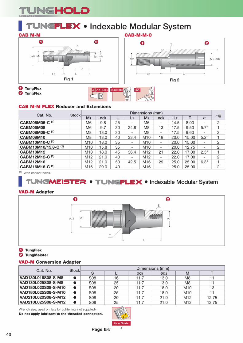
CABM06M06-C (1) M6 9.8 25 - M6 - 14.5 8.00 - 2CABM06M08 M6 9.7 30 24.8 M8 13 17.5 9.50 5.7° 1CABM08M08-C (1) M8 13.0 30 - M8 - 17.5 9.60 - 2CABM08M10 M8 13.0 40 33.4 M10 18 20.0 15.00 5.2° 1CABM10M10-C (1) M10 18.0 35 - M10 - 20.0 15.00 - 2CABM10M10/15.8-C (1) M10 15.8 35 - M10 - 20.0 12.75 - 2CABM10M12 M10 18.0 45 36.4 M12 21 22.0 17.00 2.5° 1CABM12M12-C (1) M12 21.0 40 - M12 - 22.0 17.00 - 2CABM12M16 M12 21.0 50 42.5 M16 29 25.0 25.00 6.3° 1CABM16M16-C (1) M16 29.0 40 - M16 - 25.0 25.00 - 2
M1 ød1
L2 L
M2
T
4
CAB M-M CAB-M-M-C
ød2 M2
L2 L
L1T
ød1M1
1 2 1 2
12
TungFlexTungFlex
Fig 1 Fig 2
ød2 M
T
L
S
ød1
•
1 2
S L ød1 ød2 M TVAD130L016S08-S-M8 � S08 16 11.7 13.0 M8 11VAD130L025S08-S-M8 � S08 25 11.7 13.0 M8 11VAD180L020S08-S-M10 � S08 20 11.7 18.0 M10 13VAD180L025S08-S-M10 � S08 25 11.7 18.0 M10 11VAD210L020S08-S-M12 � S08 20 11.7 21.0 M12 12.75VAD210L025S08-S-M12 � S08 25 11.7 21.0 M12 12.75
12
TungFlexTungMeister
☞
(1) With coolant holes.
User Guide
Wrench size, used on flats for tightening (not supplied).Do not apply lubricant to the threaded connection.
Designation
• Indexable Modular System
VAD-M Conversion Adapter
VAD-M Adapter
Dimensions (mm)
Dimensions (mm)
Cat. No.
Cat. No.
Stock
Stock
• Indexable Modular System
CAB M-M FLEX Reducer and Extensions
Page

41
ER32
øDM
L
øD1
10
L1
M øD øD1 L L1
ER32ODPM6X25 M6 9.8 14 25 22ER32ODPM6X50 M6 9.8 20 50 48ER32ODPM6X75 M6 9.8 23 75 74ER32ODPM8X25 M8 13.1 15 25 22ER32ODPM8X50 M8 13.1 23 50 49ER32ODPM8X75 M8 13.1 23 75 74ER32ODPM10X25 M10 18.0 20 25 23ER32ODPM10X50 M10 18.0 24 50 49ER32ODPM12X25 M12 21.0 24 25 24ER32ODPM12X50 M12 21.0 24 50 49
L L1 øD M TCDPER11M10M 0.5-7 27.0 20 16 M10 15CDPER11M12M 0.5-7 27.0 22 16 M12 17CDPER16M10M 0.5-10 38.1 20 22 M10 17CDPER16M12M 0.5-10 37.1 22 22 M12 17CDPER16M16 0.5-10 36.6 25 28 M16 25CDPER20M16 1-13 45.5 25 34 M16 25CDPER25M16 1-16 44.5 25 42 M16 28
4
L
M øD
L1
58-60 HRC N5A ➚ A 0.0031 2
1 2
12
11 26 27
CDP ER
TungFlexDIN6499
10MPa
58-60 HRCA ➚ A 0.003 N5
1
2
ER-ODP
☞User Guide
CDP-ER-M Adapter with ER Collet Chuck
ER Collet Nut Wrench
• Collet Chuck
ER-ODP ER Collet with Indexable Modular System
ER Collet •
ER ColletTungFlex
Dimensions (mm)
Dimensions (mm)
Cat. No. Stock
Cat. No. StockRange
Coolant Jet2
Page

42
L1
L
ød øDG
A 58-60 HRC ➚ A 0.003 N5
1 2
12
70 35 4
!
BT-CF
BT MAS 403 Form A/BTungFit
L L1 øD ød GBT40CF4-L 40 110 83 44.5 CF4 M16BT40CF4-S 40 52 25 44.5 CF4 M16BT50CF4-L 50 115 77 44.5 CF4 M24BT50CF4-S 50 63 25 44.5 CF4 M24
CF4 M16X1.5-CF HW8.0 M8-CF ORING3ID15
☞
BT-CF Modular System
Tightening torque: 58.8 N·mAdd B for coolant through the flange.
Lock ScrewPull Stud User Guide
Cat. No. Stock Taper
AT3 Taper
• Modular System
Spare Parts for TungFit Holders
Locking Screw Wrench Wrench O-RingSize
Dimensions (mm)
Page

43
ød1 ød
L1 L
øD øD
L
ødød
L1
øDøD1ødød2
L1L2 L
58-60 HRC N5A ➚ A 0.003
58-60 HRC N5A ➚ A 0.003
!
!
!
!
L
øDøD2 øD1
L2
L1
A B
C
C
1 2 1 2
12
12
1 2 1 2
12
12
11 26 27 435
C SEM CF
A ST-CF
D ER-CF
B EX CF
TungClickDIN3937
TungClickDIN6499
TungClickTungClick
ST CF
SEM CF
SEM CF
ER-CF D
EX CF
ød1 L L1 øD ødST25CF4 25 60 80 44 CF4ST32CF4 32 60 80 44 CF4
L L1 L2 øD ød øD1 ød2
SEM3/4CF4C 19.1 17 41.9 45 CF4 19.05 44SEM1CF4C 25.4 17 41.9 54 CF4 25.4 44
L L1 L2 øD øD1 øD2
ER11CF4-S 0.5-7 55 47 42 19 25 44
ER16CF4-L 0.5-10 100 92 42 28 25 44
ER16CF4-S 0.5-10 55 47 42 28 25 44
ER20CF4-S 1-13 55 92 42 34 25 44
ER25CF4-S 1-16 55 47 42 42 25 44
ER32CF4-L 2-20 100 92 42 50 25 44
ER32CF4-S 2-20 55 47 42 50 25 44
L L1 L2 øD ød øD1 ød2
SEM22CF4C 16 19 42 47 CF4 22 44
L L1 øD ødEXCF4-S 60 42 44 CF4EXCF4-L 100 42 44 CF4
58-60 HRC ➚ A 0.005 N5A
☞
• Modular System Adapter
Straight Shank Adapter
Tightening torque: 58.8 N·m
Tightening torque: 58.8 N·m
Shell Mill Adapter - Metric
Tightening torque: 58.8 N·m
ER Collet Adapter
Extension Adapter
Tightening torque: 58.8 N·m
Lock Screw ER Collet Nut Wrench User Guide
Straight ShankTungFit
Cat. No. Stock
Cat. No. Stock
Cat. No. Stock
Cat. No. Stock
Cat. No. Stock
Shell Endmill Holder - Inch
Dimensions (mm)
Dimensions (mm) Dimensions (mm)
Dimensions (mm)
Dimensions (mm)
Page
Range

MEMO

45
Accurate Hydraulic Chucking System
High Accuracy and Repeatability

46
is expanding its toolholder clamping options by adding hydraulic chucks. The new hydraulic chucks range from ø6-32 mm. This type of chucking system is used for rotating and stationary applications.
Main applications• Fine and accurate machining• Reaming• Drilling• Finish milling• Internal turning
Features • High runout accuracy of less than
0.003 mm• Very low torque required to activate the
clamping mechanism, by using a 4 mm Allen key• Prolongs cutting tool life and improves
surface finish due to vibration damping• Easy presetting by using an internal
preset screw• All rotating chucks feature a symmetrical and balanced design
for high speed machining of up to 15,000 min-1 • Available with threaded holes for
fine balancing• Consistent and secure clamping force
when used within the recommended speed range
• Suitable for both Weldon and cylindrical shank clamping
• Very convenient and safe tool change on the machine
Two main chuck types are available:
• Taper shanks for rotating applications• VDI DIN 69880 in sizes 30 and 40 for
stationary applications on CNC lathes

47
2.5xød
ød
0.003
Operating Instructions
To ensure correct functioning of the hydraulic chuck, the following instructions should be followed:
Tools with cylindrical shanks in accordance with DIN 1835 and DIN 6535 shape (HA) and B (HB) up to ø20 mm diameters should be manufactured according to h6 tolerance and Ramin = 0.3 ground.
Tools with DIN 6535 HE (whistle notch) shanks should be used in reduction elements, to avoid damaging the chucking hole.
• Clean any grease and dirt from the chuck mounting hole and the tool shank. Insert the tool shank up to the stopper. Make sure that the minimum chucking
length is maintained.
• Using the hexagonal-headed key, rotate the clamping screw in a clockwise direction until the end. Do not attempt to clamp the chuck without a shank inside as it may break the expansion clamping sleeve.
• To release the tool, turn the clamping screw in a counterclockwise direction
by about 5 or 6 revolutions and remove the tool.
Hydraulic Chucks System
Clamping Screw Clamping Sleeve
Hydraulic Oil
Axial Adjustment Screw

48
G Jød øD1 øD3 øD2
LminLmax
L3L1
L
58-60 HRCA ➚ A 0.003 N5
1 2
ød øD1 øD3 øD2 L L1 L3 Lmin Lmax J GBT30HYDRO6X60 6 23 26 50 60 38 43 27 37 M5
M12
BT30HYDRO8X64 8 25 28 50 64 42 43.5 27 37 M6BT30HYDRO10X64 10 27 30 50 64 42 44 32 42 M8x1BT30HYDRO12X72 12 29 32 50 72 50 44.5 37 47 M10x1BT30HYDRO14X70 14 30 34 50 70 48 47.5 37 47 M10x1BT30HYDRO16X90 16 34 38 50 90 68 47.5 42 52 M12x1BT30HYDRO18X90 18 36 40 50 90 68 47.5 42 52 M12x1BT30HYDRO20X90 20 38 42 50 90 68 47.5 42 52 M12x1BT40HYDRO6X90 6 23 26 50 90 63 43 27 37 M5
M16
BT40HYDRO8X90 8 25 28 50 90 63 43.5 27 37 M6BT40HYDRO10X90 10 27 30 50 90 63 44 32 42 M8x1BT40HYDRO12X90 12 29 32 50 90 63 44.5 37 47 M10x1BT40HYDRO14X90 14 30 34 50 90 63 47.5 37 47 M10x1BT40HYDRO16X90 16 34 38 50 90 63 47.5 42 52 M12x1BT40HYDRO18X90 18 36 40 50 90 63 47.5 42 52 M12x1BT40HYDRO20X90 20 38 42 50 90 63 47.5 42 52 M12x1BT40HYDRO25X90 25 46 50 63 90 51 51 48 58 M12x1BT40HYDRO32X110 32 56 60 60 110 81.5 81.5 52 62 M16x1BT50HYDRO6X110 6 23 26 80 110 72 43 27 37 M5
M24
BT50HYDRO8X110 8 25 28 80 110 72 43.5 27 37 M6BT50HYDRO10X110 10 27 30 80 110 72 44 32 42 M8x1BT50HYDRO12X110 12 29 32 80 110 72 42 37 47 M10x1BT50HYDRO14X110 14 30 34 80 110 72 42 37 47 M10x1BT50HYDRO16X110 16 34 38 80 110 72 45 42 52 M12x1BT50HYDRO18X110 18 36 40 80 110 72 45 42 52 M12x1BT50HYDRO20X110 20 38 42 80 110 72 47.5 42 52 M12x1BT50HYDRO25X110 25 46 50 80 110 72 47.5 48 58 M12x1BT50HYDRO32X110 32 56 60 80 110 72 47.5 54 64 M12x1
BT-HYDRO
50 70 46-47
12
BT MAS 403 Form A/BTungHydro
G6.3 BT30, 40 = 12,000 min-1
BT50 = 8,000 min-1
☞
BT-HYDRO Hydraulic Chuck Holder
Clamping wrench (wrench HYDRO HEX 4) should be ordered separately.Note: Available are reduction sleeves for ø12, 20, 25 and 32 mm bore diameters.Chucking forces will significantly reduce if reduction sleeves are used (ordered separately).
SC Collet Pull Stud User Guide
• Hydraulic Chuck Holder
Dimensions (mm)Cat. No. Stock
Page
49
50 70 46-47
ød
Lmax
Lmin
øD1 øD3
JG
L1
L
58-60 HRCA ➚ A 0.003 N5
1 2
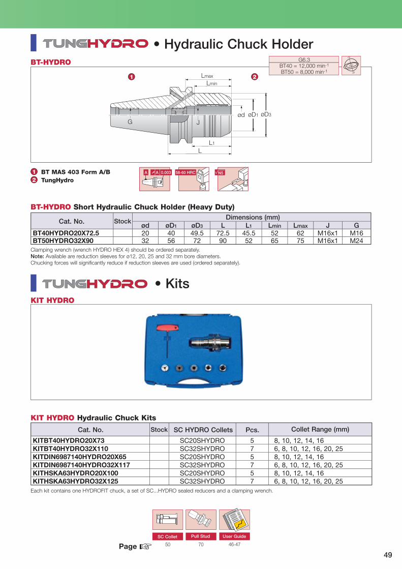
ød øD1 øD3 L L1 Lmin Lmax J GBT40HYDRO20X72.5 20 40 49.5 72.5 45.5 52 62 M16x1 M16BT50HYDRO32X90 32 56 72 90 52 65 75 M16x1 M24
BT-HYDRO
12
BT MAS 403 Form A/BTungHydro
G6.3 BT40 = 12,000 min-1
BT50 = 8,000 min-1
KITBT40HYDRO20X73 SC20SHYDRO 5 8, 10, 12, 14, 16KITBT40HYDRO32X110 SC32SHYDRO 7 6, 8, 10, 12, 16, 20, 25KITDIN6987140HYDRO20X65 SC20SHYDRO 5 8, 10, 12, 14, 16KITDIN6987140HYDRO32X117 SC32SHYDRO 7 6, 8, 10, 12, 16, 20, 25KITHSKA63HYDRO20X100 SC20SHYDRO 5 8, 10, 12, 14, 16KITHSKA63HYDRO32X125 SC32SHYDRO 7 6, 8, 10, 12, 16, 20, 25
KIT HYDRO
☞SC Collet Pull Stud User Guide
• Hydraulic Chuck Holder
BT-HYDRO Short Hydraulic Chuck Holder (Heavy Duty)
Clamping wrench (wrench HYDRO HEX 4) should be ordered separately.Note: Available are reduction sleeves for ø12, 20, 25 and 32 mm bore diameters.Chucking forces will significantly reduce if reduction sleeves are used (ordered separately).
KIT HYDRO Hydraulic Chuck Kits
Collet Range (mm)Pcs.SC HYDRO Collets
Each kit contains one HYDROFIT chuck, a set of SC...HYDRO sealed reducers and a clamping wrench.
• Kits
Dimensions (mm)Cat. No.
Cat. No.
Stock
Stock
Page

50
øD3ød2
øD1
Lmin
L2
L
ød2 Lmin øD3 L øD1 L2
SC12SHYDRO3 3 19
12 46.5 16 2SC12SHYDRO4 4 24SC12SHYDRO5 5 28SC12SHYDRO6 6 33SC12SHYDRO8 8 39SC20SHYDRO3 3 20
20 53 24 2
SC20SHYDRO4 4 25SC20SHYDRO5 5 27SC20SHYDRO6 6 34SC20SHYDRO8 8 39SC20SHYDRO10 10 40SC20SHYDRO12 12 41SC20SHYDRO14 14 44SC20SHYDRO16 16 44SC25SHYDRO6 6 37
25 60 30 4
SC25SHYDRO8 8 37SC25SHYDRO10 10 40SC25SHYDRO12 12 44SC25SHYDRO14 14 46SC25SHYDRO16 16 48SC25SHYDRO18 18 50SC25SHYDRO20 20 50SC32SHYDRO6 6 33
32 66 40 4
SC32SHYDRO8 8 38SC32SHYDRO10 10 39SC32SHYDRO12 12 42SC32SHYDRO14 14 44SC32SHYDRO16 16 44SC32SHYDRO18 18 44SC32SHYDRO20 20 49SC32SHYDRO25 25 66
SC HYDRO
SC-HYDRO Sealed SC Collet (Reduction Sleeves)
• Collet for Hydraulic Chuck
Dimensions (mm)Cat. No. Stock

51
ødh6 SW
L1Lmin
L
N·mød L L1 SW Lmin (1)
TESTBARHYDRO6 6 53 42 10 27 15TESTBARHYDRO8 8 53 42 10 27 25TESTBARHYDRO10 10 56 45 10 32 50TESTBARHYDRO12 12 62 51 10 37 110TESTBARHYDRO14 14 62 51 10 37 120TESTBARHYDRO16 16 71 54 17 37 180TESTBARHYDRO18 18 71 54 17 42 230TESTBARHYDRO20 20 71 55 17 42 250TESTBARHYDRO25 25 79 61 17 48 310TESTBARHYDRO32 32 87 65 17 52 450
J øD1
L2
W
L
J øD1 L L2 WPRESETSCREWHYDROM5 M5 5 14 1 2.5 6PRESETSCREWHYDROM6 M6 6 14 1.5 3 8PRESETSCREWHYDROM8 M8X1 8 14 2 4 10PRESETSCREWHYDROM10 M10X1 10 17 2 5 12, 14PRESETSCREWHYDROM12 M12X1 12 17 2 6 16, 18, 20PRESETSCREWHYDROM16 M16X1 14 20 2 8 20, 25, 32
PRESET SCREW HYDRO
TEST BAR HYDRO
TEST BAR HYDRO Torque Test Bars for Hydraulic Chucks
PRESET SCREW HYDRO Hydraulic Chuck Preset Screws
Used for Shanks
Clamping Torque
(1) Minimum holding length.
• Accessories
Dimensions (mm)
Dimensions (mm)
Cat. No.
Cat. No.
Stock
Stock

52
L
øD
L2G
øD1
J
L1
A 58-60 HRC ➚ A 0.003 N5
1 2
70 26 27 16 27, 30 5
BT-ER-BALANCE
12
BT MAS 403 Form ADIN6499 ER-BALANCE
GJ
L2L1
L
Lmin
Lmax
øD1øDød
58-60 HRC
•
29
BT-MAX-BALANCE
12
BT MAS 403 Form ATungBalance
N5A ➚ A 0.003
(1)G6.310,000 min-1
1 2
L L1 L2 øD øD1 G JBT40ER16X100BIN 0.5-10 100 73 44.0 28 44 M16 M10BT40ER16X150BIN 0.5-10 150 123 78.7 28 44 M16 M10BT40ER20X100BIN 1.0-13 100 73 44.6 34 44 M16 M12BT40ER20X150BIN 1.0-13 150 123 79.6 34 44 M16 M12BT40ER25X100BIN 1.0-16 100 73 43.0 42 44 M16 M16BT40ER25X150BIN 1.0-16 150 123 79.0 42 44 M16 M16BT40ER32X100BIN 2.0-20 100 73 44.0 50 60 M16 M22x1.5BT40ER32X150BIN 2.0-20 150 123 94.0 50 60 M16 M22x1.5BT40ER40X100BIN 3.0-26 100 73 44.0 63 60 M16 M28x1.5
ød øD øD1 L L1 L2 Lmin Lmax J GBT40TUNGMAX20x85BIN (1) 6-20 20 51 61 85 58 18 56 68 M16 M16BT40TUNGMAX32x108BIN (1) 6-32 32 69 80 108 81 25 70 83 M16 M16BT50TUNGMAX20x105BIN (2) 6-20 20 51 61 105 67 18 56 69 M16 M24BT50TUNGMAX32x106BIN (2) 6-32 32 69 80 106 68 25 69 83 M20x2 M24
☞
(1)(1) G2.520,000 min-1
Pull Stud Nut Wrench ER Collet Preset Screw User Guide
AT3 Taper
Balanceable Rings
Range
• Balanceable Collet Chuck Holder
(1) Blanced to G2.5 at max. n: 20,000 min-1
Wrench is not included.
(1) Chucks with taper size 40 can be balanced by the balancing ring up to G2.5 at max. n: 20,000 min-1(2) Chucks with taper size 50 can be balanced by the balancing ring up to G2.5 at max. n: 18,000 min-1
Wrench is not included.
SC Collet
Range
• BALANCE • Endmill Chuck Holder
Dimensions (mm)
Dimensions (mm)
Cat. No.
Cat. No.
Stock
Stock
BT-MAX-BALANCE Balanceable Power Chuck Holder
BT-ER-BALANCE Balanceable ER Collet Chuck Holder
Page

53
øD1øD
L
L1
D2
L3
L2
G øD2
A 58-60 HRC ➚ A 0.003 N5
1 2
70 26 27 16 27 23
ADJ BT-ER
0.1 mm 1°
G2.520,000 min-1
12
BT MAS 403 Form A/BDIN6499
øD
L
G
L1
L2
C T
øD1
58-60 HRC N5
1 2
GTI BT-ER
12
BT MAS 403 Form ADIN6499 GTI
L L1 L2 L3 øD øD1 øD2 GADJBT40D70ER32 2-20 129.5 52.5 102.5 92.5 50 70 62.5 M16ADJBT50D70ER32 2-20 144.5 52.5 106.5 - 50 70 - M24
G L L1 L2 øD øD1 T CGTIBT40ER16 M3-M10 0.5-10 M16 84.2 52.7 24.6 28 29.5 8 3GTIBT40ER32 M6-M20 2-20 M16 106.8 79.8 33 50 56.5 9 4GTIBT40ER40 M6-M28 3-26 M16 124.8 97.8 51 63 56.5 9 4GTIBT50ER16 M3-M10 0.5-10 M24 106.8 68.8 24.6 28 29.5 8 3GTIBT50ER32 M6-M20 2-20 M24 115.2 77.2 33 50 56.5 9 4GTIBT50ER40 M6-M28 3-26 M24 133.2 95.2 51 63 56.5 9 4
☞
ADJ BT-ER ER Collet Chuck with Center Alignment
Nut ER Collet Preset Screw User Guide
AT3 Taper
Pull Stud Wrench
• ER Collet Chuck with Center Alignment
GTI BT-ER Tapping Holder
Cat. No. Stock Tap Capacity
AT3 Taper
• Tapping Holder
Range
Range
Dimensions (mm)
Dimensions (mm)
Cat. No. Stock
Page
Wrench is not included.
Wrench is not included.
54
L2
øD1
L1
øD
TC
L
øD2
58-60 HRC N5
1 2
16 26 27 5
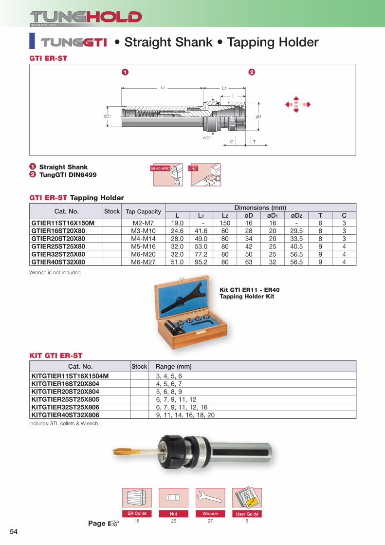
GTI ER-ST
KIT GTI ER-ST
12
L L1 L2 øD øD1 øD2 T CGTIER11ST16X150M M2-M7 19.0 - 150 16 16 - 6 3GTIER16ST20X80 M3-M10 24.6 41.6 80 28 20 29.5 8 3GTIER20ST20X80 M4-M14 28.0 49.0 80 34 20 33.5 8 3GTIER25ST25X80 M5-M16 32.0 53.0 80 42 25 40.5 9 4GTIER32ST25X80 M6-M20 32.0 77.2 80 50 25 56.5 9 4GTIER40ST32X80 M6-M27 51.0 95.2 80 63 32 56.5 9 4
KITGTIER11ST16X1504M 3, 4, 5, 6KITGTIER16ST20X804 4, 5, 6, 7KITGTIER20ST20X804 5, 6, 8, 9KITGTIER25ST25X805 6, 7, 9, 11, 12KITGTIER32ST25X806 6, 7, 9, 11, 12, 16KITGTIER40ST32X806 9, 11, 14, 16, 18, 20
☞
• Straight Shank • Tapping Holder
GTI ER-ST Tapping Holder
Includes GTI, collets & Wrench
Kit GTI ER11 - ER40 Tapping Holder Kit
ER Collet Nut Wrench User Guide
Straight ShankTungGTI DIN6499
Cat. No. Stock Range (mm)
Cat. No. Stock Tap CapacityDimensions (mm)
Page
Wrench is not included.

55
LL1
øD
KG1G
øD
K
L1
L
G
A 58-60 HRC ➚ A 0.005 N5
A
B
1 2 1 2
12
A BT-AD B BT-MT
12
BT MAS 403 Form ADIN2080DIN69871/ABT MAS 403
BT MAS 403 Form ADIN6383DIN228-2 Form D
70
K L L1 øD G1 GBT40AD30 DIN2080 60 33 50 M12 M16BT50ADBT/SK40 DIN69871/A, BT MAS-403 75 37 66 M16 M24BT50AD40 DIN2080 70 32 63 M16 M24
K L L1 øD GBT30MT1X45 MT1 45 23 25 M12BT30MT2X60 MT2 60 38 32 M12BT40MT1X45 MT1 45 18 25 M16BT40MT1X120 MT1 120 93 25 M16BT40MT2X60 MT2 60 33 32 M16BT40MT2X120 MT2 120 93 32 M16BT40MT3X75 MT3 75 48 40 M16BT40MT3X139 MT3 139 112 40 M16BT40MT4X95 MT4 95 68 50 M16BT50MT1X45 MT1 45 7 25 M24BT50MT1X120 MT1 120 82 25 M24BT50MT1X180 MT1 180 142 25 M24BT50MT2X45 MT2 45 7 32 M24BT50MT2X135 MT2 135 97 32 M24BT50MT2X180 MT2 180 142 32 M24BT50MT3X45 MT3 45 7 40 M24BT50MT3X150 MT3 150 112 40 M24BT50MT3X180 MT3 180 142 40 M24BT50MT4X75 MT4 75 37 50 M24BT50MT4X180 MT4 180 142 50 M24BT50MT5X105 MT5 105 67 70 M24
☞
BT-AD Conversion Adapter
BT-MT Morse Taper Holder
Pull Stud
AT3 Taper
Conversion Adapter / Morse Taper Holder
Dimensions (mm)
Dimensions (mm)
Cat. No.
Cat. No.
Stock
Stock
Page

56
L
KG1G
L1
øD
L2L
L1
A 58-60 HRC ➚ A 0.005 N5
1 2
12
BT MAS 403 Form ADIN6364DIN228-2 Form B
G
L
K
L1
øD
1 2
12
BT MAS 403 Form ADIN238
K L L1 L2 øD G1 GBT40MT1DRW MT1 50 23 - 25 M6 M16BT40MT2DRW MT2 50 23 - 32 M10 M16BT40MT3DRW MT3 70 43 - 40 M12 M16BT40MT4DRW (1) MT4 95 68 15 63 M16 M16BT50MT1DRW MT1 45 7 - 25 M6 M24BT50MT2DRW MT2 60 22 - 32 M10 M24BT50MT3DRW MT3 65 27 - 40 M12 M24BT50MT4DRW(1) MT4 70 32 15 63 M16 M24BT50MT5DRW(1) MT5 100 62 18 78 M20 M24
K L øD L1 GBT30DCB12X30 B12 30 - 8.0 M12BT30DCB16X30 B16 30 - 8.0 M12BT40DCB12X45 B12 45 24 18.0 M16BT40DCB12X90 B12 90 24 63.0 M16BT40DCB16X45 B16 45 30 18.0 M16BT40DCB16X90 B16 90 30 63.0 M16BT40DCB18X45 B18 45 30 18.0 M16BT40DCB18X90 B18 90 30 63.0 M16BT50DCB12X45 B12 45 - 6.7 M24BT50DCB12X105 B12 105 24 67.0 M24BT50DCB16X45 B16 45 - 7.0 M24BT50DCB16X105 B16 105 50 67.0 M24BT50DCB18X45 B18 45 - 7.0 M24BT50DCB18X105 B18 105 30 67.0 M24
BT-MT-DRWA
A
B
BT-DC-BB
70☞
BT-MT-DRW Morse Taper Draw Bar type Hplder
(1) DIN2201.
AT3 Taper
Morse Taper Holder / Drill Chuck Holder
BT-DC-B Drill Chuck Holder
Dimensions (mm)
Dimensions (mm)
Cat. No.
Cat. No.
Stock
Stock
Pull Stud
Page

57
300℃
L(mm)
Max T.I.R(µm)
35 760 985 10
Thermal Shrink Chucking System Thermal Shrink ER Collet Chucking System is an enhancement to the existing popular ER system.The SHRINK collets utilize the thermal shrink phenomenon for rigid clamping of solid carbide cutters. This new system provides higher torque, precision runout and better repeatability. The SHRINK collets with their slim design and various projection lengths allow the user to reach into deeper shaped cavities and perform narrow milling applications.Tungaloy offers a complete system for SHRINK ER collets, including a uniquely designed heating unit with a portable heating handle. The s is equipped with a high-tech temperature control for easy and practical use at the machining center or in the tool room.
Clamping time15-45 seconds
Features:• Slim design with various
projections• Flexible - fits into
standard ER chucks• High torque transfer• Rigid clamping of
carbide tools• Precision runout• Perfect repeatability
• Vibration damping• Internal coolant• Coolant JET2 available• Symmetrical design for high
speed machining• Quick and easy tool
changing• Unique SHRINK heating
unit with portable handle
Standard ER Collet
SHRINK ER Collet

58
ød
ød
ød
ød
BT (30, 40, 50)
BT (30, 40, 50)
ER20ER25ER32
BT-SRK, SRKIN
Standard ER Collet Chuck
SHORTIN
SHRINK ER Collet Compatible with StandardER Collets DIN 6499
Thermal Shrink Chucking System

59
4°30’
LminM6
øD øD1
L
L1
J
G ød
Lmax
L2
G
Lmax
J
Lmin
4˚
øDød
L2
L1
øD1
L
A 50-52 HRC ➚ A 0.003 N5
A
B
(2) (3)
12
12
1 2 1 2
A BT-SHRINK B BT-SHRINK
66 685770 35
(2), (3)
G2.525,000 min-1
ød øD1 øD L L1 L2 Lmin Lmax J GBT40SRKIN6X90 6 27 21 90 63 38.0 25 36 M5 M16 2.5BT40SRKIN8X90 8 27 21 90 63 38.0 25 36 M6 M16 3.0BT40SRKIN10X90 10 32 24 90 63 50.5 31 42 M8 M16 4.0BT40SRKIN12X90 12 32 24 90 63 50.5 36 47 M10 M16 5.0BT40SRKIN14X90 14 34 27 90 63 44.5 36 47 M10 M16 5.0BT40SRKIN16X90 16 34 27 90 63 44.5 39 50 M12 M16 6.0BT40SRKIN18X90 18 42 33 90 63 57.0 39 50 M12 M16 6.0BT40SRKIN20X90 20 42 33 90 63 57.0 41 52 M16 M16 8.0BT40SRKIN25X110 25 53 44 110 83 57.0 47 58 M16 M16 8.0BT50SRKIN6X100 (1) 6 26 21 100 62 32.0 25 36 M5 M24 2.5BT50SRKIN8X100 (1) 8 27 21 100 62 38.0 25 36 M6 M24 3.0BT50SRKIN10X100 (1) 10 32 24 100 62 51.0 31 42 M8 M24 4.0BT50SRKIN12X100 (1) 12 32 24 100 62 51.0 36 47 M10 M24 5.0BT50SRKIN14X100 (1) 14 34 27 100 62 44.5 36 47 M10 M24 5.0BT50SRKIN16X100 (1) 16 34 27 100 62 44.5 39 50 M12 M24 6.0BT50SRKIN18X100 (1) 18 42 33 100 62 57.0 39 50 M12 M24 6.0BT50SRKIN20X100 (1) 20 42 33 100 62 57.0 41 52 M16 M24 8.0BT50SRKIN25X120 (1) 25 53 44 120 82 57.0 47 58 M16 M24 8.0BT50SRKIN32X120 (1) 32 53 44 120 82 57.0 47 58 M16 M24 8.0
ød øD øD1 L L1 L2 Lmin Lmax J GBT40SRK3X50 3 10 15 77 50 35.5 10 16 M6 M16 3BT40SRK3X85 3 10 19 112 85 64.1 10 16 M6 M16 3BT40SRK4X50 4 10 15 77 50 35.5 12 18 M6 M16 3BT40SRK4X85 4 10 19 112 85 64.1 12 18 M6 M16 3BT40SRK5X50 5 10 15 77 50 35.5 15 21 M6 M16 3BT40SRK5X85 5 10 19 112 85 64.1 15 21 M6 M16 3BT40SRK6X50 6 11 16 77 50 35.5 18 24 M8 M16 4BT40SRK6X85 6 11 20 112 85 64.1 18 24 M8 M16 4BT40SRK8X50 8 14 20 77 50 42.5 25 31 M10 M16 5BT40SRK8X85 8 14 23 112 85 63.9 25 31 M10 M16 5BT40SRK10X50 10 16 22 77 50 42.4 30 36 M12 M16 6BT40SRK10X85 10 16 25 112 85 60.2 30 36 M12 M16 6BT40SRK12X50 12 20 26 77 50 42.3 32 42 M10 M16 5BT40SRK12X85 12 20 28 112 85 56.6 32 42 M10 M16 5
(3)
G2.525,000 min-1
☞
BT MAS 403 Form A SRK (for carbide shank)
BT MAS 403 Form A SRKIN (for carbide and HSS shank)
BT-SHRINK Thermal SHRINK Holder (SRKIN type for carbide and HSS shank) (3)
(1) Balanced to G2.5 at max. n: 20,000 min-1
Use only inductive heating device for SRKIN holders.
User GuidePull Stud Induction Thermal Preset Screw
Hex Key
Hex Key
AT3 Taper
• Thermal SHRINK Holder
BT-SHRINK Thermal SHRINK Holder (SRK type for carbide shank) (2) (3)
Dimensions (mm)
Dimensions (mm)
Cat. No.
Cat. No.
Stock
Stock
Page

60
4˚
øD øD1
L
L1
J
ød
Lmax
Lmin
4˚
øD øD1
L
L1
J
ød
Lmax
Lmin
10MPa
58-60 HRCA ➚ A 0.003 N5
ER..SRK...
576668
ER20, ER25-SHRINK
12
DIN6499TungShrink
(1)
ød L L1 Lmin Lmax øD1 øD JER20SRK3X35 3.00 35.00 24.5 10.0 16.00 13.5 10.0 M6 3ER20SRK3X60 3.00 60.00 24.5 10.0 16.00 13.5 10.0 M6 3ER20SRK4X35 4.00 35.00 24.5 12.0 18.00 13.5 10.0 M6 3ER20SRK4X60 4.00 60.00 24.5 12.0 18.00 13.5 10.0 M6 3ER20SRK5X35 5.00 35.00 24.5 15.0 21.00 13.5 10.0 M6 3ER20SRK5X60 5.00 60.00 24.5 15.0 21.00 13.5 10.0 M6 3ER20SRK6X35 6.00 35.00 25.5 18.0 24.00 14.7 11.0 M8 4ER20SRK6X60 6.00 60.00 29.5 18.0 24.00 15.2 11.0 M8 4ER25SRK3X35 3.00 35.00 24.5 10.0 16.00 13.5 10.0 M6 3ER25SRK3X60 3.00 60.00 44.5 10.0 16.00 16.3 10.0 M6 3ER25SRK4X35 4.00 35.00 24.5 12.0 18.00 13.5 10.0 M6 3ER25SRK4X60 4.00 60.00 44.5 12.0 18.00 16.3 10.0 M6 3ER25SRK5X35 5.00 35.00 24.5 15.0 21.00 13.5 10.0 M6 3ER25SRK5X60 5.00 60.00 44.5 15.0 21.00 16.3 10.0 M6 3ER25SRK6X35 6.00 35.00 26.0 18.0 24.00 14.7 11.0 M8 4ER25SRK6X60 6.00 60.00 44.5 18.0 24.00 17.3 11.0 M8 4ER25SRK8X35 8.00 35.00 26.5 25.0 30.00 17.8 14.0 M10 5ER25SRK8X60 8.00 60.00 39.5 25.0 31.00 19.7 14.0 M10 5
1 2 1 2
☞
Coolant JET2
(1) For JET2 collet, add JET2 to the designations (i.e. ER25SRK8x35JET2).
Thermal Induction User Guide
Wrench
(1) ER..SRKJET2...(JET2 type External coolant)
ER20, ER25-SHRINK SHRINK ER Collet SRK type (DIN6499) - Metric
• Collet for Shrink
Dimensions (mm)Cat. No. Stock
Page

61
576668
4˚
øD øD1
L
L1
J
ød
Lmax
Lmin
4˚
øD øD1
L
L1
J
ød
Lmax
Lmin
ER32SRK...
10MPa
58-60 HRCA ➚ A 0.003 N5
1 2 1 2
ER32-SHRINK
12
DIN6499TungShrink
ød L L1 Lmin Lmax øD1 øD JER32SRK3X35 3.00 35.00 22.5 10.0 16.00 13.2 10.0 M6 3ER32SRK3X60 3.00 60.00 44.5 10.0 16.00 16.3 10.0 M6 3ER32SRK3X85 3.00 85.00 70.0 10.0 16.00 19.8 10.0 M6 3ER32SRK4X35 4.00 35.00 23.5 12.0 18.00 13.4 10.0 M6 3ER32SRK4X60 4.00 60.00 44.5 12.0 18.00 16.3 10.0 M6 3ER32SRK4X85 4.00 85.00 70.0 12.0 18.00 19.8 10.0 M6 3ER32SRK5X35 5.00 35.00 24.5 15.0 21.00 13.5 10.0 M6 3ER32SRK5X60 5.00 60.00 44.5 15.0 21.00 16.3 10.0 M6 3ER32SRK5X85 5.00 85.00 70.0 15.0 21.00 19.8 10.0 M6 3ER32SRK6X35 6.00 35.00 25.5 18.0 24.00 14.7 11.0 M8 4ER32SRK6X60 6.00 60.00 45.0 18.0 24.00 17.3 11.0 M8 4ER32SRK6X85 6.00 85.00 69.5 18.0 26.00 20.8 11.0 M8 4ER32SRK8X35 8.00 35.00 33.0 25.0 31.00 18.8 14.0 M10 5ER32SRK8X60 8.00 60.00 45.0 25.0 31.00 20.4 14.0 M10 5ER32SRK8X85 8.00 85.00 65.0 25.0 31.00 23.2 14.0 M10 5ER32SRK10X35 10.00 35.00 34.0 30.0 35.00 20.8 16.0 M12 6ER32SRK10X60 10.00 60.00 44.5 30.0 36.00 22.4 16.0 M12 6ER32SRK10X85 10.00 85.00 49.5 30.0 36.00 23.0 16.0 M12 6ER32SRK12X35 12.00 35.00 28.0 32.0 - 24.0 20.0 - -ER32SRK12X60 12.00 60.00 28.0 32.0 38.00 24.0 20.0 M14 6ER32SRK12X85 12.00 85.00 28.0 32.0 38.00 24.0 20.0 M14 6
☞Thermal Induction User Guide
Coolant JET2
Wrench
(1) ER32SRKJET2...(JET2 type External coolant)
• Collet for Shrink
(1) For JET2 collet, add JET2 to the designations (i.e. ER32SRK12X85JET2).
Dimensions (mm)Cat. No. Stock
ER32-SHRINK SHRINK ER Collet SRK type (DIN6499) - Metric
Page

62
ød øD
Lmax
Lmin4°
L1
L
ød1øD1h6
1 2
58-60 HRC N5A ➚ A 0.003
ød øD øD1 ød1 L L1 Lmin LmaxST12X160SRK3 3 10 12 4 160 14.3 10 -ST12X160SRK4 4 10 12 4 160 14.3 12 27ST16X160SRK3 3 10 16 6 160 43.0 10 -ST16X160SRK4 4 10 16 6 160 43.0 12 -ST16X160SRK5 5 10 16 6 160 43.0 15 -ST16X160SRK6 6 11 16 6 160 35.5 18 35ST20X200SRK5 5 10 20 6 200 71.5 15 -ST20X200SRK6 6 11 20 6 200 64.5 18 40ST20X200SRK8 8 14 20 6 200 43.0 25 40ST25X200SRK6 6 11 25 8 200 100.0 18 35ST25X200SRK8 8 14 25 8 200 78.6 25 40ST25X200SRK10 10 16 25 8 200 64.3 30 50ST25X200SRK12 12 20 25 8 200 35.7 32 52
ST-SHRINK G2.520,000 min-1
12
576668☞
• Straight Shank
Straight ShankTungShrink
ST-SHRINK Thermal SHRINK Holder Straight Shank SRK type - MetricDimensions (mm)
Cat. No. Stock
Thermal Induction User Guide
Page
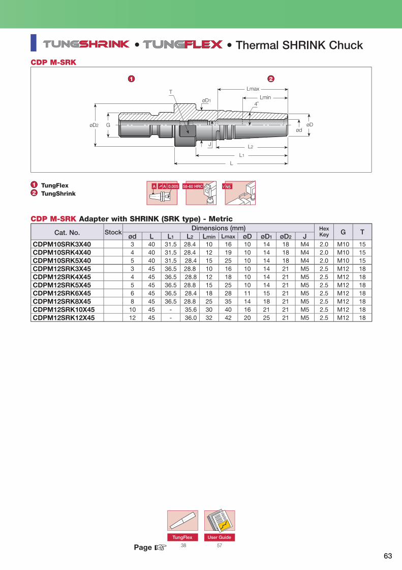
63
4˚
GøD2 øDød
L
L1
L2
øD1
TLmax
Lmin
J
•
58-60 HRC N5A ➚ A 0.005
1 2
5738
CDP M-SRK
12
TungFlexTungShrink
TungFlex
G Tød L L1 L2 Lmin Lmax øD øD1 øD2 J
CDPM10SRK3X40 3 40 31.5 28.4 10 16 10 14 18 M4 2.0 M10 15CDPM10SRK4X40 4 40 31.5 28.4 12 19 10 14 18 M4 2.0 M10 15CDPM10SRK5X40 5 40 31.5 28.4 15 25 10 14 18 M4 2.0 M10 15CDPM12SRK3X45 3 45 36.5 28.8 10 16 10 14 21 M5 2.5 M12 18CDPM12SRK4X45 4 45 36.5 28.8 12 18 10 14 21 M5 2.5 M12 18CDPM12SRK5X45 5 45 36.5 28.8 15 25 10 14 21 M5 2.5 M12 18CDPM12SRK6X45 6 45 36.5 28.4 18 28 11 15 21 M5 2.5 M12 18CDPM12SRK8X45 8 45 36.5 28.8 25 35 14 18 21 M5 2.5 M12 18CDPM12SRK10X45 10 45 - 35.6 30 40 16 21 21 M5 2.5 M12 18CDPM12SRK12X45 12 45 - 36.0 32 42 20 25 21 M5 2.5 M12 18
☞
CDP M-SRK Adapter with SHRINK (SRK type) - MetricHexKey
• Thermal SHRINK Chuck
User Guide
Dimensions (mm)Cat. No. Stock
Page

64
L
G
øD
A 58-60 HRC ➚ A 0.003 N5
!
1 2
BT-ER-CLICK
70 2765
G2.520,000 min-1
12
BT MAS 403 Form ADIN6499 ER-CLICK
TungClick
G2.520,000 min-1
L øD GBT40ER32CLICK-IN 28 41 M16BT50ER32CLICK-IN 39 41 M24
•
☞Pull Stud
BT-ER-CLICK Quick Change System
Tightening torque: 235 N·m
Wrench
AT3 Taper
• Quick Change Holder
Face Contact Advantages:
• Taper and face contact.• Ideal for high speed machining.• High precision runout.• High rigidity.• Quick and easy clamping (half a turn).
Quick-Change System
Dimensions (mm)Cat. No. Stock
Page
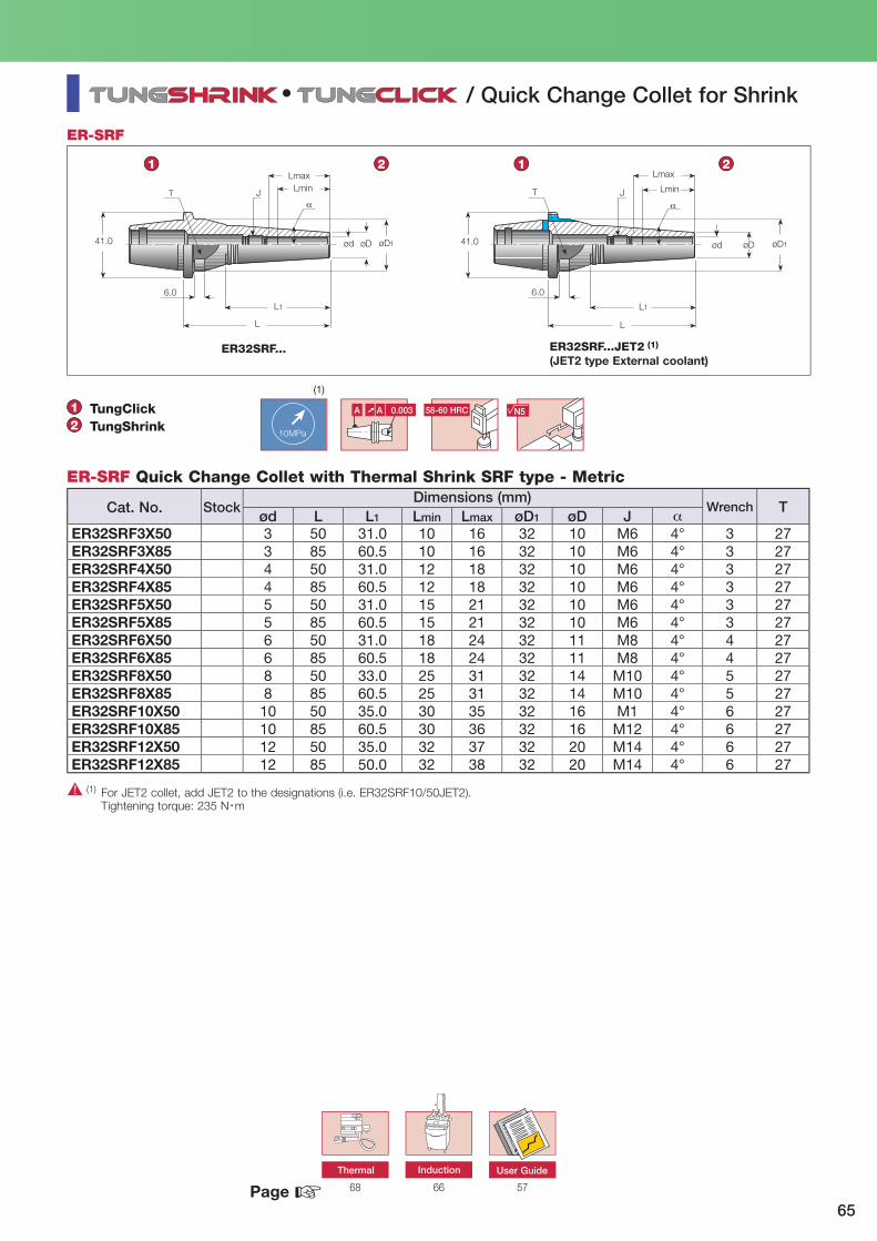
65
41.0
T J
L
L1
6.0
øD øD1
LmaxLmin
41.0
T J
L
L1
6.0
øD øD1ød
Lmax
Lmin
ød
!
10MPa
58-60 HRCA ➚ A 0.003
1 2 1 2
576668
ER-SRF
ER32SRF...
•
12
TungClickTungShrink
N5
(1)
Tød L L1 Lmin Lmax øD1 øD J α
ER32SRF3X50 3 50 31.0 10 16 32 10 M6 4° 3 27ER32SRF3X85 3 85 60.5 10 16 32 10 M6 4° 3 27ER32SRF4X50 4 50 31.0 12 18 32 10 M6 4° 3 27ER32SRF4X85 4 85 60.5 12 18 32 10 M6 4° 3 27ER32SRF5X50 5 50 31.0 15 21 32 10 M6 4° 3 27ER32SRF5X85 5 85 60.5 15 21 32 10 M6 4° 3 27ER32SRF6X50 6 50 31.0 18 24 32 11 M8 4° 4 27ER32SRF6X85 6 85 60.5 18 24 32 11 M8 4° 4 27ER32SRF8X50 8 50 33.0 25 31 32 14 M10 4° 5 27ER32SRF8X85 8 85 60.5 25 31 32 14 M10 4° 5 27ER32SRF10X50 10 50 35.0 30 35 32 16 M1 4° 6 27ER32SRF10X85 10 85 60.5 30 36 32 16 M12 4° 6 27ER32SRF12X50 12 50 35.0 32 37 32 20 M14 4° 6 27ER32SRF12X85 12 85 50.0 32 38 32 20 M14 4° 6 27
☞
ER-SRF Quick Change Collet with Thermal Shrink SRF type - Metric
(1) For JET2 collet, add JET2 to the designations (i.e. ER32SRF10/50JET2). Tightening torque: 235 N・m
Thermal Induction User Guide
Wrench
ER32SRF...JET2 (1)
(JET2 type External coolant)
/ Quick Change Collet for Shrink
Dimensions (mm)Cat. No. Stock
Page

66
Easy and efficient to operateQuick tool changing (5 sec.)Short cooling time (30 sec.)Range of ShankSolid carbide range 3-32 mmH.S.S. cutter range 6-32 mm
Suitable for:Integral toolingIntegral heavy duty toolingExtensionsER..SRK... unique collets
••••
Induction Heating Unit
Integral SRKINER... SRK
Integral SRK
Technical Specifications:Clamping range : 3 ~ 32 mm Carbide tool shankClamping range : 6 ~ 32 mm HSS & steel shankMain power supply : 3 x 380 ~ 500 V, 50 / 60 HzNominal power : 10 kWNominal current : 16 AMPCooling unit power supply : 220 V, 50 / 60 HzNominal power : 0.5 kWMax. tool length : 440 mm (from gauge line)Max. dia. clamping chuck : 52 mmEffective induction field length : 45 mmExpansion time : approx. 5 ~ 12 secondsCooling time : approx. 50 ~ 90 secondsWeight : 150 kgOverall dimensions : 1700 x 730 x 600 mm

67
INDCOOLINGCOLLET6-8
SRKININDCOOLINGCOLLET10-12INDCOOLINGCOLLET14-16INDCOOLINGCOLLET18-20INDCOOLINGCOLLETER3-5
SRKINDCOOLINGCOLLETER6INDCOOLINGCOLLETER8INDCOOLINGCOLLETER10INDCOOLING OLLETER12
IND32TOOLADAPTERIND40TOOLADAPTERIND50TOOLADAPTER (1)
IND63TOOLADAPTERIND80TOOLADAPTER
INDSHRINKINUNITEUR
Includes:Induction unitCooling unitTrolleyThree Tool Adapter (1)
SHRINK Thermal Electrical Unit
Cat. No.
(1) For taper #30
For coolant water (1.8 gallons), onlymineral water canbe used
Cooling Conector - in
Coil Conector
Main Switch
Cooling Switch
CoolingConector - out
Trolley
Main WorkingPost #50, HSK 100
Tool(1)
Adapter #40, HSK 63
CoolingHouse
Tray forCutting Tools
ControlPanel
Drawer for Adapter
Induction Main Unit
Coil Rings
Induction Starter Unit Cat. No. :4505585 IND SHRINK START UNIT EUR
INDUCTION Starter UnitThe induction starter unit is an economical starter version of the SHRINK induction unit. It was designed to help the enduser to purchase the modern shrink chucking technology in a low cost device. The starter unit is actually a simplified and limited version of the complete inductive system that we offer today:
Cooling Sleeves Used for
Optional Tool Adapter for HSK

68
SHRINKINUNITV2EUR HEATINGHANDLE220VV2
Thermal Heating UnitV2 Version
Start Heating Button
Portable Heating Unit Holder
Main Switch + Fan
Heating Power Switch(ON/OFF)
TemperatureDisplay
Cooling Rack
Set 2-Safety Setting Control500°C
Pocket for ER32
Pocket for ER40
Portable Heating UnitConnection Plug
Set 1- OperatingTemperature (Max 485°C)
Portable Heating UnitRange: 3-12 mm
Portable Heating Unit Handle
SHRINK Thermal Electric Unit Portable Heating Unit Handle
Important Note: This thermal heating unit can be used only for heating ER.. SRK and ER.. SRF collets.
220V 50/60 HZ
Cat. No. Cat. No.

69
SETER32SRKS6EUR 4, 5, 6, 8, 10, 12
SETER32SRKM6EUR 4, 5, 6, 8, 10, 12
SETER32SRKL6EUR 4, 5, 6, 8, 10, 12
SETER32SRKS6USA 0.187, 0.25, 0.312, 0.375, 0.437, 0.5
SETER32SRKM6USA 0.187, 0.25, 0.312, 0.375, 0.437, 0.5
SETER32SRKL6USA 0.187, 0.25, 0.312, 0.375, 0.437, 0.5
KITSHRINKINSV2EUR 220V 50/60 Hz 4, 5, 6, 8, 10, 12
KITSHRINKINMV2EUR 220V 50/60 Hz 4, 5, 6, 8, 10, 12
KITSHRINKINLV2EUR 220V 50/60 Hz 4, 5, 6, 8, 10, 12
SHRINK ER 32 Collet Sets and Kits
ER32 SHRINK Set6 Collets (4-12)
SHRINK Thermal Electric Unit Kit withER32 SHRINK 6 Piece Collet Set (4-12)
Cat. No. Collet Size (mm)
Cat. No. Collet Size (inch)
Cat. No. Power Suppl Collet Size (mm)
Note: Size table is inch.

70
Fig G ød1 ød2 ød4 ød5 L L1 L2 α
PSBT3015°M12JISB � M12 12.00 8.0 13 4.0 18.4 43.0 23.4 15° 1PSBT4015°M16JISB � M16 19.00 14.0 17 5.5 23 54.0 29.0 15° 1PSBT4015°M16JISOB � M16 19.00 14.0 17 5.5 23 54.0 29.0 15° 2PSBT4015°M16JISOBO M16 19.00 14.0 17 5.5 23 54.0 29.0 15° 3PSBT4015°M16JIS40B � M16 19.00 14.0 17 4.0 23 54.0 29.0 15° 2PSBT5015°M24JISB � M24 28.00 21.0 25 8.0 25 74.0 34.0 15° 1PSBT5015°M24JISOB � M24 28.00 21.0 25 8.0 25 74.0 34.0 15° 2PSBT5015°M24JISOBO M24 28.00 21.0 25 8.0 25 74.0 34.0 15° 3PSBT4045°M16MAZAKB M16 18.79 12.4 17 7.0 14.026 44.1 19.1 45° 1PSBT5045°M24MAZAKB M24 28.95 20.8 25 8.0 17.58 65.2 25.2 45° 1
ød1 Gød5
ød2 ød4
L2
L
L1
58-60 HRC N5
ød2ød4
L2L
L1
ød1 ød5 G
Fig G ød1 ød2 ød4 ød5 L L1 L2 α
PSBT3045°M12MAS1 � M12 11 7 12.5 - 18 43 23 45° 1PSBT3045°M12MAS1B � M12 11 7 12.5 3 18 43 23 45° 1PSBT3060°M12MAS2 � M12 11 7 12.5 - 18 43 23 60° 1PSBT3060°M12MAS2B M12 11 7 12.5 3 18 43 23 60° 1PSBT4045°M16MAS1 � M16 15 10 17.0 - 28 60 35 45° 1PSBT4045°M16MAS1B � M16 15 10 17.0 5.5 28 60 35 45° 1PSBT4060°M16MAS2 � M16 15 10 17.0 - 28 60 35 60° 1PSBT4060°M16MAS2B � M16 15 10 17.0 5.5 28 60 35 60° 1PSBT4090°M16MAS3 � M16 15 10 17.0 - 28 60 35 90° 1PSBT4090°M16MAS3B � M16 15 10 17.0 5.5 28 60 35 90° 1PSBT5045°M24MAS1 � M24 23 17 25.0 - 35 85 45 45° 1PSBT5045°M24MAS1B � M24 23 17 25.0 6.0 35 85 45 45° 1PSBT5045°M24MAS1OB � M24 23 17 25.0 6.0 35 85 45 45° 2PSBT5045°M24MAS1OBO M24 23 17 25.0 6.0 35 85 45 45° 3PSBT5060°M24MAS2 � M24 23 17 25.0 - 35 85 45 60° 1PSBT5060°M24MAS2B � M24 23 17 25.0 6.0 35 85 45 60° 1PSBT5060°M24MAS2OB M24 23 17 25.0 6.0 35 85 45 60° 2PSBT5090°M24MAS3 � M24 23 17 25.0 - 35 85 45 90° 1PSBT5090°M24MAS3B � M24 23 17 25.0 6.0 35 85 45 90° 1PSBT5090°M24MAS3OB � M24 23 17 25.0 6.0 35 85 45 90° 2
58-60 HRC N5
PS BT-JIS / MAZAK
PS BT-MAS
Fig 3Fig 1 Fig 2
Fig 3Fig 1 Fig 2
Fig 1: Coolant holes only in items with a "B" suffix. Fig 2: With external O-ring. Fig 3: With external and internal O-rings.
PS BT-JIS / MAZAK Pull Stud BT-JIS/ANSI - Metric
Fig 1: Coolant holes only in items with a "B" suffix. Fig 2: With external O-ring. Fig 3: With external and internal O-rings.
PS BT-MAS Pull Stud BT-MAS - Metric
Pull Stud
Dimensions (mm)
Dimensions (mm)
Cat. No.
Cat. No.
Stock
Stock
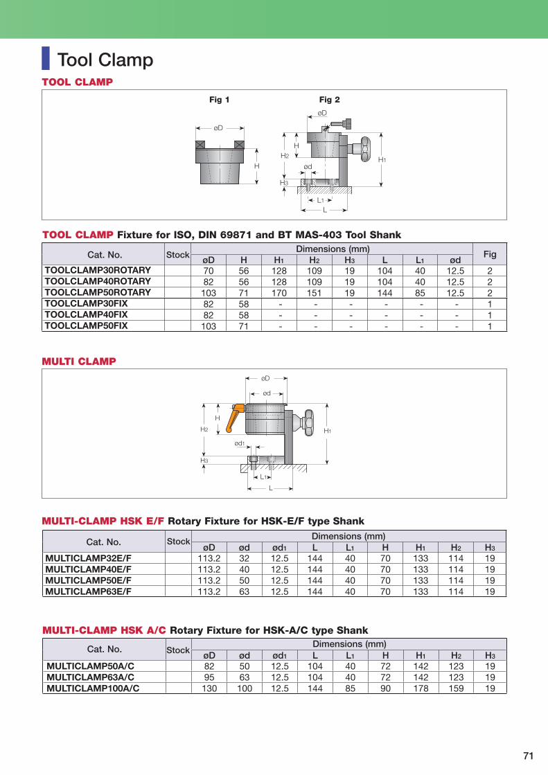
71
L1
L
H3
H2
H
ød
øD
H1
øD
H
L1
L
H
H2
H3
ød1
ød
øD
H1
MULTI CLAMP
Fig 1 Fig 2
FigøD H H1 H2 H3 L L1 ød
TOOLCLAMP30ROTARY 70 56 128 109 19 104 40 12.5 2TOOLCLAMP40ROTARY 82 56 128 109 19 104 40 12.5 2TOOLCLAMP50ROTARY 103 71 170 151 19 144 85 12.5 2TOOLCLAMP30FIX 82 58 - - - - - - 1TOOLCLAMP40FIX 82 58 - - - - - - 1TOOLCLAMP50FIX 103 71 - - - - - - 1
øD ød ød1 L L1 H H1 H2 H3
MULTICLAMP32E/F 113.2 32 12.5 144 40 70 133 114 19MULTICLAMP40E/F 113.2 40 12.5 144 40 70 133 114 19MULTICLAMP50E/F 113.2 50 12.5 144 40 70 133 114 19MULTICLAMP63E/F 113.2 63 12.5 144 40 70 133 114 19
øD ød ød1 L L1 H H1 H2 H3
MULTICLAMP50A/C 82 50 12.5 104 40 72 142 123 19MULTICLAMP63A/C 95 63 12.5 104 40 72 142 123 19MULTICLAMP100A/C 130 100 12.5 144 85 90 178 159 19
TOOL CLAMP Fixture for ISO, DIN 69871 and BT MAS-403 Tool Shank
MULTI-CLAMP HSK E/F Rotary Fixture for HSK-E/F type Shank
Tool Clamp
MULTI-CLAMP HSK A/C Rotary Fixture for HSK-A/C type Shank
TOOL CLAMP
Dimensions (mm)
Dimensions (mm)
Dimensions (mm)
Cat. No.
Cat. No.
Cat. No.
Stock
Stock
Stock

72
TP50AD40EASY EASYLOCKTROLLEY
WRENCHER16EASYLOCK TP40AD30EASY
WRENCHER20EASYLOCK TP50ADHSK63EASY
WRENCHER25EASYLOCK TP50ADHSK100EASY
WRENCHER32EASYLOCK
WRENCHER40EASYLOCK WRENCHER50EASYLOCK
WRENCHTG100OPENEASY
AccessoriesStandard Optional
EASYLOCKT.CEU
Easy Lock Unit
Table Model
Specifications
Euro Motor: 1 phase 200/240V 50/60 HZ 1 KnWeight: Table model - 85 KG. Trolley (optional) - 15 Kgf.
• Ensures controlled (proper) clamping of cutting tools• Maintains collet chuck accuracy• Easy clamping and unclamping of cutting tools• Handy set for various collet chuck sizes• Main spindle taper #50• Suitable for main shank standards #40, #50, HSK 63, HSK 100
Electrical Nut-Clamp Torque Control Device
Cat. No.
Electrical Nut-Clamp Torque Control Device

73
510
510630
550
600
340
700
500
540
Electrical Nut-Clamp Torque Control Device
Power Clamping Unit for Collet Chucks
Power Lamp
Ensure that main power switch is on and that the power supply cable is connected.
To unclamp - Push and hold in the “unclamp” button until the collet chuck is totally open.
Mount the collet chuck into the unit spindle.
Note: Assemble the collet and cutting tool. By hand, place the nut onto the collet chuck.
To clamp - Push and hold in the “clamp” button until the bottom light goes off.
Torque Selector NEW
Place the wrench on the collet chuck nut.
Choose the correct wrench size. Mount iton the wrench holder.
Trolley (optional)
(Unit: mm)

74
b
L6
ød6 ød5
ød
ød1
L4
ød3 G
L1
8°17’50”
af3
f1
20°
e1e1
ød12
BT MAS 403
Form A
BT MAS 403 Form A/B
a b (H12) ød ød1 G ød3 (H8) ød5 ød6 (H8) f1 ±0.1BT30 2 16.1 8 31.75 M12 12.5 56.144 46 13.6BT40 2 16.1 10 44.45 M16 17.0 75.679 63 16.6BT50 3 25.7 15 69.85 M24 25.0 119.020 100 23.2
f3 L1 ±0.2 L4 min L6-0.2 e1 ±0.1 ød12
BT30 20 48.4 24 16.3 21 4 0.002BT40 25 65.4 30 22.6 27 4 0.003BT50 35 101.8 45 35.4 42 6 0.004
Form BInternal Coolant Flange
Shank Stock
Shank Stock TAPER AT3
max. 35°
• Shank Standaed
Dimensions (mm)
Dimensions (mm)

MEMO

Tungaloy Rus, LLC36-G Kostukova str.308012 Belgorod, RussiaPhone:+7 4722 58 57 57 Fax:+7 4722 58 57 83www.tungaloy.co.jp/ru
Tungaloy Polska Sp. z o.o.ul. Genewska 2403-963 Warszawa, PolandPhone: +48-22-617-0890 Fax: +48-22-617-0890www.tungaloy.co.jp/pl
Tungaloy U.K. LtdHilton Hall Business Centre, EssingtonStaffordshire, WV11 2BQ, UKPhone:+44 121 309 0163 Fax: +44 121 270 9694 www.tungaloy.co.jp/uk [email protected]
Tungaloy Hungary KftErzsébet királyné útja 125H-1142 Budapest, Hungary Phone: +36 1 781-6846 Fax: +36 1 781-6866www.tungaloy.co.jp/hu [email protected]
Tungaloy TurkeyDudullu Organize Sanayi Bolgesi DESSanayi Sitesi 1 Cadde Ticaret, Merkezi No. 3/734779 Ümraniye Istanbul, Turkey Phone: +90 216 540 04 67 Fax: +90 216 540 04 87www.tungaloy.co.jp/tr [email protected]
Tungaloy Cutting Tool (Shanghai) Co.,Ltd.Rm No 401 No.88 Zhabei, Jiangchang No.3 RdShanghai 200436, ChinaPhone: +86-21-3632-1880 Fax: +86-21-3621-1918www.tungaloy.co.jp/tcts
Tungaloy Cutting Tool (Thailand) Co.,Ltd.11th Floor, Sorachai Bldg. 23/7, Soi Sukhumvit 63Klongtonnue, Wattana, Bangkok 10110, ThailandPhone: +66-2-714-3130 Fax: +66-2-714-3134www.tungaloy.co.th
Tungaloy Singapore (Pte.), Ltd.31 Kaki Bukit Road 3, #05-19 TechLinkSingapore 417818Phone:+65-6391-1833 Fax:+65-6299-4557www.tungaloy.co.jp/tspl
Tungaloy India Pvt. Ltd.Unit#13, B wing, 8th Floor, Kamala Mills Compound Trade World, Lower Parel (West), Mumbai - 4000 13. IndiaPhone: +91-22-6124-8804 Fax: +91-22-6124-8899www.tungaloy.co.jp/in
Tungaloy Korea Co., Ltd#1312, Byucksan Digital Valley 5-chaBeotkkot-ro 244, Geumcheon-gu153-788 Seoul, KoreaPhone:+82-2-2621-6161 Fax:+82-2-6393-8952www.tungaloy.co.jp/krr
Tungaloy Malaysia Sdn Bhd50 K-2, Kelana Mall, Jalan SS6/14, Kelana Jaya, 47301 Petaling Jaya, Selangor Darul Ehsan, MalaysiaPhone:+603-7805-3222 Fax:+603-7804-8563www.tungaloy.co.jp/my
Tungaloy Australia Pty LtdUnit 308/33 Lexington DriveBella Vista NSW 2153, AustraliaPhone:+612-9672-6844 Fax:+612-9672-6866www.tungaloy.co.jp/au
Tungaloy Corporation (Head offi ce)11-1 Yoshima-KogyodanchiIwaki-city, Fukushima, 970-1144 JapanPhone: +81-246-36-8501 Fax: +81-246-36-8542www.tungaloy.co.jp
Tungaloy America, Inc.3726 N Ventura Drive, Arlington Heights, IL 60004, U.S.A.Phone: +1-888-554-8394 Fax: +1-888-554-8392www.tungaloyamerica.com
Tungaloy Canada 432 Elgin St. Unit 3, Brantford, Ontario N3S 7P7, Canada Phone: +1-519-758-5779 Fax: +1-519-758-5791 www.tungaloyamerica.com
Tungaloy de Mexico S.A.C Los Arellano 113, Parque Industrial Siglo XXIAguascalientes, AGS, Mexico 20290Phone:+52-449-929-5410 Fax:+52-449-929-5411www.tungaloyamerica.com
Tungaloy do Brasil Comércio de Ferramentas de Corte Ltda.Rua dos Sabias N.10413280-000 Vinhedo, São Paulo, BrazilPhone:+55-19-38262757 Fax:+55-19-38262757www.tungaloy.co.jp/br
Tungaloy Germany GmbHAn der Alten Ziegelei 1D-40789 Monheim, GermanyPhone: +49-2173-90420-0 Fax: +49-2173-90420-19www.tungaloy.de
Tungaloy France S.A.S.ZA Courtaboeuf - Le Rio, 1 rue de la Terre de feuF-91952 Courtaboeuf Cedex, FrancePhone: +33-1-6486-4300 Fax: +33-1-6907-7817www.tungaloy.fr
Tungaloy Italia S.r.I.Via E. Andolfato 10I-20126 Milano, ItalyPhone: +39-02-252012-1 Fax: +39-02-252012-65www.tungaloy.it
Tungaloy Czech s.r.oTuranka 115CZ-627 00 Brno, Czech RepublicPhone: +420-532 123 391 Fax: +420-532 123 392www.tungaloy.cz
Tungaloy Ibérica S.L.C/Miquel Servet, 43B, Nau 7, Pol. Ind. BufalventES-08243 Manresa (BCN), SpainPhone:+34 93 113 1360 Fax:+34 93 876 2798www.tungaloy.es
Tungaloy Scandinavia ABS:t Lars Väg 42ASE-22270 Lund, SwedenPhone:+46-462119200 Fax:+46-462119207www.tungaloy.se
Distributed by:
Sep. 2012 (TJ)
ISO 9001 certifi ed ISO 14001 certifi edQC00J0056 EC97J1123Tungaloy Corporation Tungaloy Group Japan site and Asian production site18/10/1996 26/11/1997


