
Unit 3Transport layer
Departamento deTecnología Electrónica
Computer NetworkingSome of these slides are given as copyrighted material from: Computer Networking: A
Top Down Approach ,5th edition.
Jim Kurose, Keith RossAddison-Wesley, April
2009.

Transport Layer 3-2
Unit 3: Transport LayerOur goals: Understanding the
principles behind transport layer services: multiplexing &
demultiplexing reliable data transfer flow control
learn about transport layer protocols in the Internet: UDP: connectionless transport TCP: connection-oriented
transport

Transport Layer 3-3
Unit 3.Overview
3.1 Transport-layer services3.2 Multiplexing and demultiplexing3.3 Connectionless transport: UDP3.4 Principles of reliable data transfer3.5 Connection-oriented transport: TCP
segment structure reliable data transfer flow control connection management

Transport Layer 3-4
Transport services and protocols provide logical communication
between app processes running on different hosts
transport protocols run in end systems send side: breaks app
messages into segments, passes to network layer
rcv side: reassembles segments into messages, passes to app layer
more than one transport protocol available to apps Internet: TCP and UDP
applicationtransportnetworkdata linkphysical
applicationtransportnetworkdata linkphysical
logical end-end transport
Transport Layer 3-5
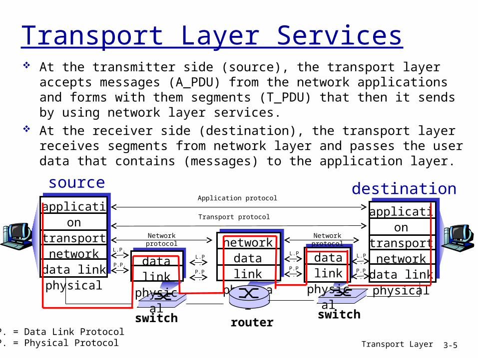
Transport Layer Services At the transmitter side (source), the transport layer accepts messages (A_PDU)
from the network applications and forms with them segments (T_PDU) that then it sends by using network layer services.
At the receiver side (destination), the transport layer receives segments from network layer and passes the user data that contains (messages) to the application layer.
sourceapplicationtransportnetworkdata linkphysical
destinationapplicationtransportnetworkdata linkphysical
networkdata linkphysical
data linkphysical
routerswitch
data linkphysical
switch
Application protocol
Transport protocol
Network protocol Network protocol
L.P.
P.P.L.P.
P.P.
L.P.
P.P.
L.P.
P.P.
L.P. = Data Link ProtocolP.P. = Physical Protocol

Transport Layer 3-6
Transport vs. network layer
network layer: provides a logical communication service between hosts Similar to postal service that sends a letter to a postal address
transport layer: extends the network service to provide a logical communication service between application processes It’s known as transport layer multiplexion and demultiplexion It relies on, enhances, network layer services

Transport Layer 3-7
Transport vs. network layer
Household analogy:Two houses with 10 kids in each one. They send letters among
them every week. processes = kids app messages = letters in envelopes hosts = houses transport protocol = Ann (in one house) and Bill (in the other
house) are responsible for picking up their brothers’ letters, sending them using the Postal Office, waiting for incoming letters and delivering them to their brothers
network-layer protocol = postal service

Transport Layer 3-8
Internet transport-layer protocols
TCP: reliable, in-order delivery congestion control flow control connection setup
UDP: unreliable, unordered delivery extension of “best-effort” IP
Not available services: Guaranteed delay Guaranteed bandwidth
applicationtransportnetworkdata linkphysical
networkdata linkphysical
networkdata linkphysical
networkdata linkphysical
networkdata linkphysical
networkdata linkphysical
networkdata linkphysical
applicationtransportnetworkdata linkphysical
logical end-end transport

Transport Layer 3-9
Unit 3. Overview.
3.1 Transport-layer services3.2 Multiplexing and demultiplexing3.3 Connectionless transport: UDP3.4 Principles of reliable data transfer3.5 Connection-oriented transport: TCP
segment structure reliable data transfer flow control connection management

Transport Layer 3-10
Multiplexing/demultiplexing
application
transport
network
link
physical
P1 application
transport
network
link
physical
application
transport
network
link
physical
P2P3 P4P1
host 1 host 2 host 3
= process= socket
delivering received segments (T_PDU)to correct socket, by using the header (T_PCI)
Demultiplexing at recv host:gathering data from multiplesockets, enveloping data (T_PDU) with header (T_PCI) (later used for demultiplexing)
Multiplexing at send host:
Transport Layer 3-11
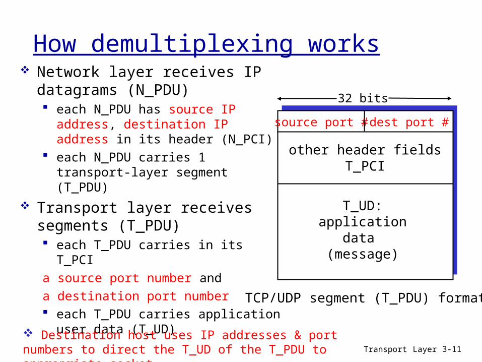
How demultiplexing works Network layer receives IP datagrams
(N_PDU) each N_PDU has source IP address,
destination IP address in its header (N_PCI)
each N_PDU carries 1 transport-layer segment (T_PDU)
Transport layer receives segments (T_PDU) each T_PDU carries in its T_PCI a source port number anda destination port number each T_PDU carries application user
data (T_UD)
source port # dest port #
32 bits
T_UD:application
data (message)
other header fieldsT_PCI
TCP/UDP segment (T_PDU) format
Destination host uses IP addresses & port numbers to direct the T_UD of the T_PDU to appropriate socket

Transport Layer 3-12
Connectionless demultiplexing (UDP)
Create UDP sockets by using an specific host-local port number or using one unused:
DatagramSocket mySocket1 = new DatagramSocket(12534);
DatagramSocket mySocket2 = new DatagramSocket();
When source host creates the T_IDU to send into UDP socket, must specify (in T_ICI):
(dest IP address, dest port number)
when UDP protocol in destination host receives the segment (T_PDU): checks destination port
number in header segment (T_PCI)
directs user data (T_UD) of the T_PDU to UDP socket with that port number
Demux (UDP) doesn’t check source IP addresses and/or source port numbers
Transport Layer 3-13
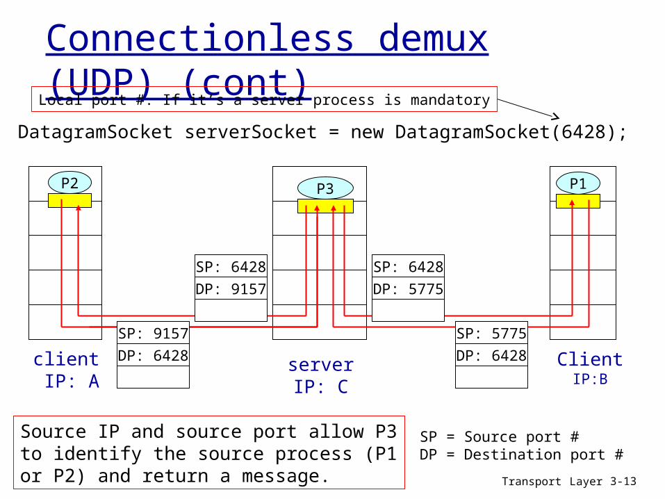
Connectionless demux (UDP) (cont)
DatagramSocket serverSocket = new DatagramSocket(6428);
ClientIP:B
P2
client IP: A
P1P1P3
serverIP: C
SP: 6428DP: 9157
SP: 9157DP: 6428
SP: 6428DP: 5775
SP: 5775DP: 6428
Source IP and source port allow P3 to identify the source process (P1 or P2) and return a message.
Local port #. If it’s a server process is mandatory
SP = Source port #DP = Destination port #

Transport Layer 3-14
Connection-oriented demux (TCP)
TCP socket identified by 4-tuple: source IP address source port number dest IP address dest port number
recv host uses all four values (in N_PCI and T_PCI) to direct segment (T_PDU) to appropriate TCP socket
server host may support many simultaneous TCP sockets: each socket identified by its
own 4-tuple web servers have different
TCP sockets for each connecting client non-persistent HTTP will have
different socket for each request

Transport Layer 3-15
Connection-oriented demux (TCP)
When creating TCP socket… … port number must be
indicated at the server. Port must be “listening”
ServerSocket WelcomeSocket = new ServerSocket(6789);
… server socket (IP & port) must be provided as T_ICI. Connection with server’s socket is established.
Socket ClientSocket = new Socket(“ServerHostname", 6789);
… when the server receives a connection request from the client, server must accept connection. Connection is identified by the client socket (IP & port) and the server socket (IP & port)
Socket socketConnection = welcomeSocket.accept();
When destination host receives a T_PDU, it must check both source and destination ports in the Transport header (T_PCI). It also must check both source and destination IP addresses in the N_ICI. Then, it must send the user data (T_UD) to the correct application process.

Transport Layer 3-16
Connection-oriented demux (TCP)Web server with several process
clientIP: B
P1
client IP: A
P1P2P4
serverIP: C
SP: 9157DP: 80
SP: 9157DP: 80
P5 P6 P3
D-IP:CS-IP: AD-IP:C
S-IP: B
SP: 5775DP: 80
D-IP:CS-IP: B
No problem if two clients process use the same
source port
No problem if two clients process use the
same source IPSP = Source port #DP = Destination port #S-IP = Source IP addressD-IP = Destination IP address
Transport Layer 3-17
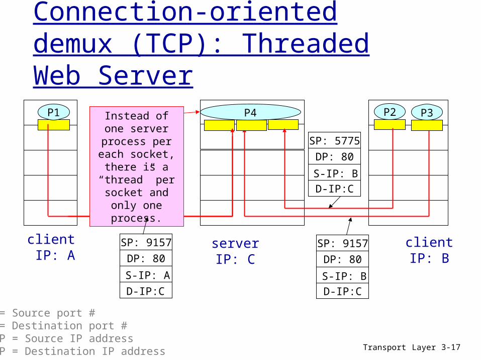
Connection-oriented demux (TCP): Threaded Web Server
P1
client IP: A
P1P2
serverIP: C
SP: 9157DP: 80
SP: 9157DP: 80
P4 P3
D-IP:CS-IP: AD-IP:C
S-IP: B
SP: 5775DP: 80
D-IP:CS-IP: B
SP = Source port #DP = Destination port #S-IP = Source IP addressD-IP = Destination IP address
Instead of one server process per each socket, there is a “thread” per socket and only
one process.
clientIP: B

Transport Layer 3-18
Unit 3. Overview
3.1 Transport-layer services3.2 Multiplexing and demultiplexing3.3 Connectionless transport: UDP3.4 Principles of reliable data transfer3.5 Connection-oriented transport: TCP
segment structure reliable data transfer flow control connection management
Transport Layer 3-19
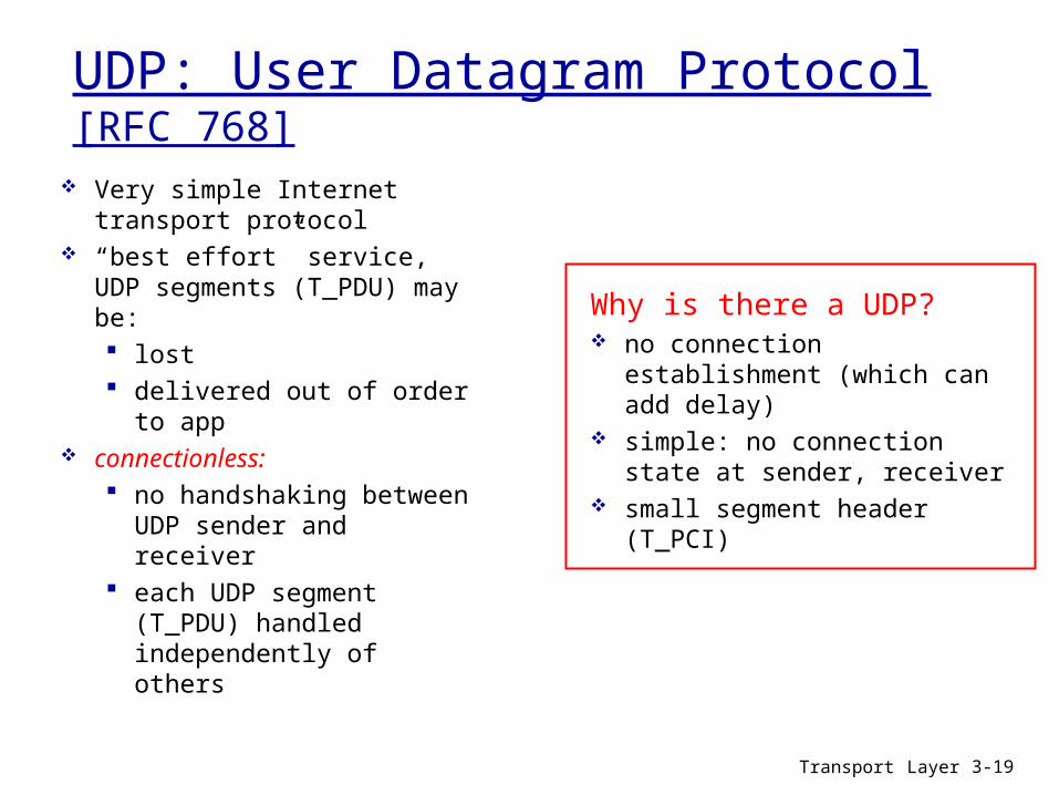
UDP: User Datagram Protocol [RFC 768]
Very simple Internet transport protocol
“best effort” service, UDP segments (T_PDU) may be: lost delivered out of order to
app connectionless:
no handshaking between UDP sender and receiver
each UDP segment (T_PDU) handled independently of others
Why is there a UDP? no connection establishment
(which can add delay) simple: no connection state at
sender, receiver small segment header (T_PCI)
Transport Layer 3-20
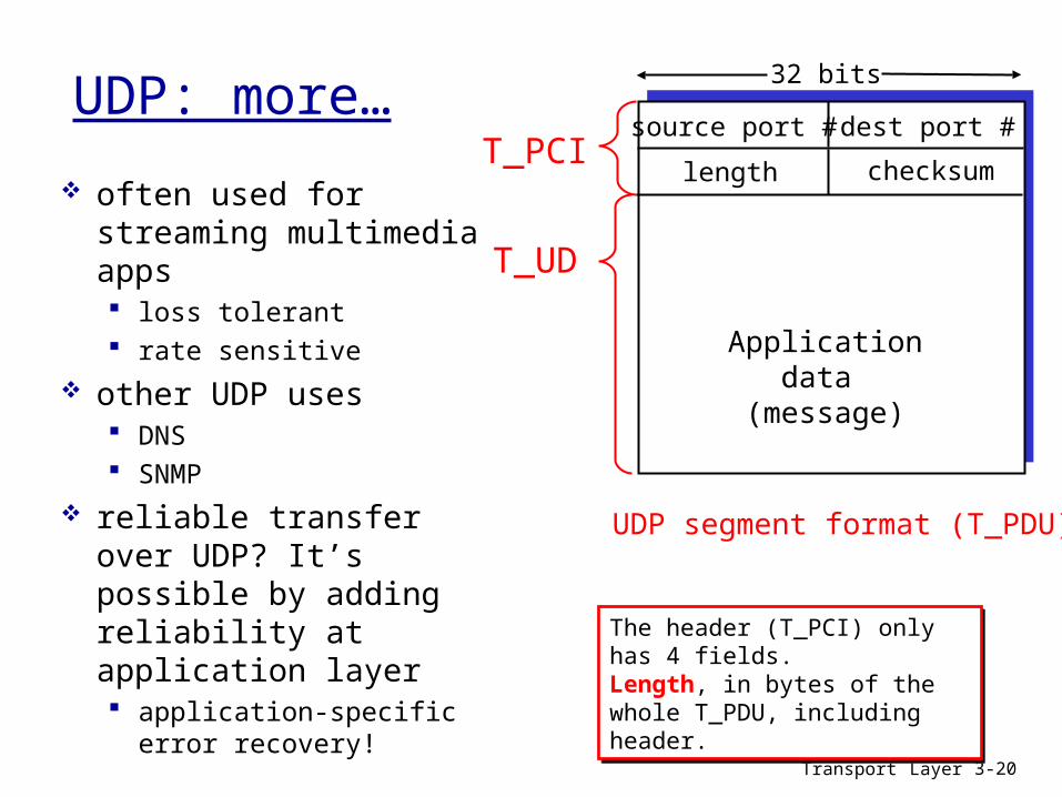
UDP: more…
often used for streaming multimedia apps loss tolerant rate sensitive
other UDP uses DNS SNMP
reliable transfer over UDP? It’s possible by adding reliability at application layer application-specific error
recovery!
source port # dest port #
32 bits
Applicationdata
(message)
UDP segment format (T_PDU)
length checksumT_PCI
T_UD
The header (T_PCI) only has 4 fields. Length, in bytes of the whole T_PDU, including header.
The header (T_PCI) only has 4 fields. Length, in bytes of the whole T_PDU, including header.

Transport Layer 3-21
UDP checksum
Sender (simplified): treat T_PDU segment contents
as sequence of 16-bit integers checksum: addition of segment
contents with carryout, then 1’s complement
sender puts checksum value into UDP checksum field (T_PCI)
Receiver: compute checksum of received
segment check if computed checksum
equals checksum field value: NO - error detected YES - no error detected. But
maybe errors nonetheless? More later ….
Goal: detect “errors” (e.g., flipped bits) in transmitted segment (T_PDU)

Transport Layer 3-22
Internet Checksum Example Note: when adding numbers, a carryout from the
most significant bit needs to be added to the result at the right-most position.
Example: add two 16-bit integers
1 1 1 1 0 0 1 1 0 0 1 1 0 0 1 1 01 1 1 0 1 0 1 0 1 0 1 0 1 0 1 0 1
1 1 0 1 1 1 0 1 1 1 0 1 1 1 0 1 1 11 1 0 1 1 1 0 1 1 1 0 1 1 1 1 0 01 0 1 0 0 0 1 0 0 0 1 0 0 0 0 1 1
carryout
sum (with carryout)checksum

Transport Layer 3-23
Unit 3. Overview
3.1 Transport-layer services3.2 Multiplexing and demultiplexing3.3 Connectionless transport: UDP3.4 Principles of reliable data transfer3.5 Connection-oriented transport: TCP
segment structure reliable data transfer flow control connection management

Why is reliable transfer necessary? wrong PDUsInterferences in link transmission
can change transmitted bits. lost PDUs When packet queue is full incoming
packets are dropped. duplicated PDUs Communication failures make
already received PDUs be retransmitted.
How are these problems detected? wrong PDUsError checking mechanisms (included in
PCI). E.g. Checksum Most complex and reliable algoritms are used in
data link layer. lost and duplicated PDUsAdding “something” in the header (PCI) of
each PDU to distinguish it from the rest of the sent PDUs.
How are these problems resolved? RetransmissionSender transmits again the PDU that had
problems.
Important in application, transport and link layers top-10 list of important networking topics!
Principles of Reliable data transfer
Transport Layer 3-24

General case of communication between peers entities in a same layer: To communicate to its peer entity, an entity sends the other a PDU makes
up a header (PCI) and, in general, user data (UD). Headers (PCI) contains protocol control information. In general, both entities transmit and receive user data. Bidirectional transfer of user data between peers entities.
Simplification of this general case: Makes easier the explanation of the principles of reliable data transfer. Suppose an unidirectional user data transfer. One of these peer entities is a transmitter (Tx) and the other is the
receiver (Rx). Tx transmits PDUs with PCI and UD (UD comes from the above layer). Rx receives PDUs with PCI and UD (UD goes to the above layer). Rx transmits PDUs that only contents PCI (without UD, only control info.) Bidirectional protocol control information transfer.
Principles of Reliable data transfer
Transport Layer 3-25

What types of PDU are used? Data PDU
Sent by the Tx Contents user data (UD) Contents protocol control information (PCI)
Control PDU Sent by the Rx Does not carry user data (UD) Contents only protocol control information (PCI)
It’s wrong to think that Tx doesn’t send control information and sends only data PDUs.
Data PDUs also carry control information.
It’s wrong to think that Tx doesn’t send control information and sends only data PDUs.
Data PDUs also carry control information.
Notice that
Principles of Reliable data transfer
Transport Layer 3-26

What does the header (PCI) content?The PCI of a data PDU contents information that allows:
Rx detecting if the data PDU has errors. Identifying the data PDU and distinguishing it from the others PDUs sent
by Tx.The PCI of a control PDU contents information that allows:
Tx detecting if the control PDU contents errors. Rx identifying a particular data PDU, and reports that the data PDU:
has been received OK by the Rx: ACK, acknowledgement, return receipt
Has not been received OK by the Rx: NAK, NACK, Negative acknowledgement, negative return receipt
Information in PCI that is for identifying a particular data PDU is called sequence number.
Information in PCI that is for identifying a particular data PDU is called sequence number.
Note
Principles of Reliable data transfer
Transport Layer 3-27

Principles of Reliable data transfer Tx basic operation:
The Tx entity in a particular layer forms a data PDU with UD and PCI and transmits it to the Rx.
Now, Tx waits for some time, known as time_out, until it receives a control PDU from the Rx. The control PDU indicates:
Data PDU received OK, with an ACK.o Tx doesn’t do anything
else. Data PDU received with
errors, with a NACK.o Tx retransmits the PDU.
If time_out expires before control PDU from Rx arrives, theno Tx retransmits the PDU.
Rx basic operation: When receiving a data PDU, Rx
entity in a layer: If the data PDU arrives OK,
it is mandatory that Rx sends Tx an ACK control PDU to notify it.
If the data PDU arrives with errors, it is optional that Rx sends Tx a NACK control PDU to notify it.
Q: How long should time_out be, as minimum?
Q: Does Rx pass always to the above layer the UD contained in a data PDU received OK?
Transport Layer 3-28

Example 1. Tx sends only a PDU with UD and doesn’t send
the next until the transmission is sucessful. Rx only sends ACK control PDU.
Tx Rx
PDU 1
Time
Without errors
ACK 1PDU 2
ACK 2
PDU 3
ACK 3
PDU X
ACK X
dtransPDU
dtransack
PCI
Tx Rx
PDU 1
PDU 2
X
PDU 1
ACK 1
Time_out
Time_out
PDU 2
ACK 2
With errors
Lost PDU
wrong PDU
Principles of reliable data transfer
Transport Layer 3-29

Example 2. Idem example 1.Rx also sends NACK control
PDU.Without errors.
Same behaviour as previous e.g.
Tx Rx
PDU 1
timePDU 2
XNACK 1
PDU 1
ACK 1
PDU 2
Time_out
ACK 2
With errors
Principles of reliable data transfer
Transport Layer 3-30

The mechanism that guarantees a reliable data transfer is known as a stop-and-wait protocol
It’s not much efficient Tx must stop and wait for receiving the ACK before sending the next PDU.
Is it possible to measure transfer performance? To simplify, let’s suppose that:
Tx always has a ready PDU to send, There isn’t any error, Each PDU has L bytes of UD and 0 bytes of PCI, dtransack = 0.
Utilization of the Tx or channel (U tx) = fraction of time that Tx/channel is busy transmitting bits of the PDU.
Principles of reliable data transfer
Transport Layer 3-31

Stop-and-wait protocol performance
First PDU bit sent, t = 0Last PDU bit sent, t = L/R
Tx Rx
RTT
First PDU bit received Last PDU bit received, send ACK
ACK received, t = RTT+L/RSend next PDU
U tx =
L / R
RTT + L / R
dtrans = L/R
Remember
Transport Layer 3-32

The protocol works but its performance is poor Example: 1 Gbps link, RTT = 30 ms, PDU = 1KByte
ssb
pdukb
R
Ldtrans 8
/10
/89
1 PDU of 1KByte every 30,008 msec 33,3kByte/sec effective transfer rate in a 1 Gbps link
Protocol can limit the capabilities provided by the underlying network hardware!
Is it possible to improve it?
00027,0008,30
008,0
/
/
RLRTT
RLU tx
Stop-and-wait protocol performance
Transport Layer 3-33

Protocols with pipelining Pipelining: Tx is allowed to send multiple PDUs (“in-flight”)
without waiting for acknowledgements (ACK), improving performance by far. Sequence numbers used in PCI must have enough range to distinguish
all in-transit PDUs. Buffers are needed in Tx and, sometimes, in Rx
Stop-and-wait Pipelining
PDU PDU
ACK
Note: We’ll study in depth this concept when studying TCP Transport Layer 3-34

Transport Layer 3-35
Pipelining: increased utilization
Send bit 1 of 1st PDU, t = 0
Tx Rx
RTT
Send last bit of PDU, t = L / R
First bit of 1st PDU arrivesLast bit of 1st PDU arrives, send ACK
ACK received, send next PDU, the 4th, t = RTT + L / R
Last bit 2nd PDU arrives, send ACKLast bit 3rd PDU arrives, send ACK
U tx
= 0,024
30,008 = 0,0008
microseconds
3 * L / R
RTT + L / R =
Increase utilizationby a factor of 3!

Transport Layer 3-36
Reliable data transfer service How does transport layer provide a reliable data transfer service to
the application layer?

Transport Layer 3-37
Reliable data transfer service How does transport layer provide a reliable data transfer service to
the application layer?
Transport layer is above network layer that provides an unreliable data transfer service.
Transport Layer 3-38
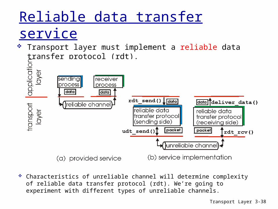
Reliable data transfer service Transport layer must implement a reliable data transfer protocol (rdt).
Characteristics of unreliable channel will determine complexity of reliable data transfer protocol (rdt). We’re going to experiment with different types of unreliable channels.
Transport Layer 3-39
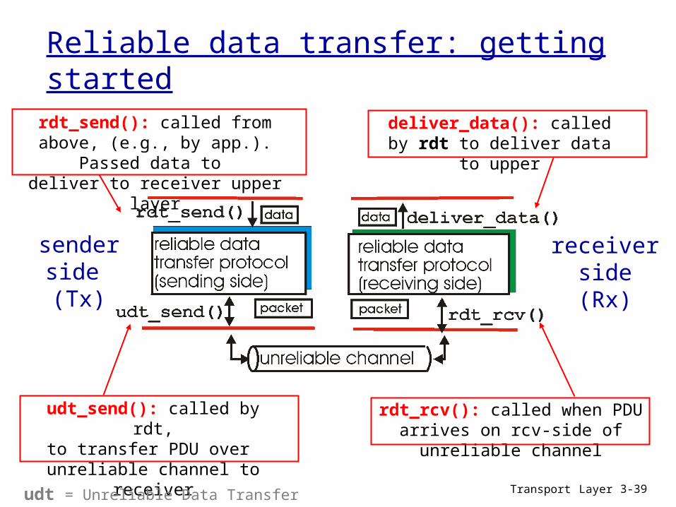
Reliable data transfer: getting started
senderside (Tx)
receiverside(Rx)
rdt_send(): called from above, (e.g., by app.). Passed data to
deliver to receiver upper layer
udt_send(): called by rdt,to transfer PDU over
unreliable channel to receiver
rdt_rcv(): called when PDU arrives on rcv-side of unreliable channel
deliver_data(): called by rdt to deliver data to upper
udt = Unreliable Data Transfer
Transport Layer 3-40
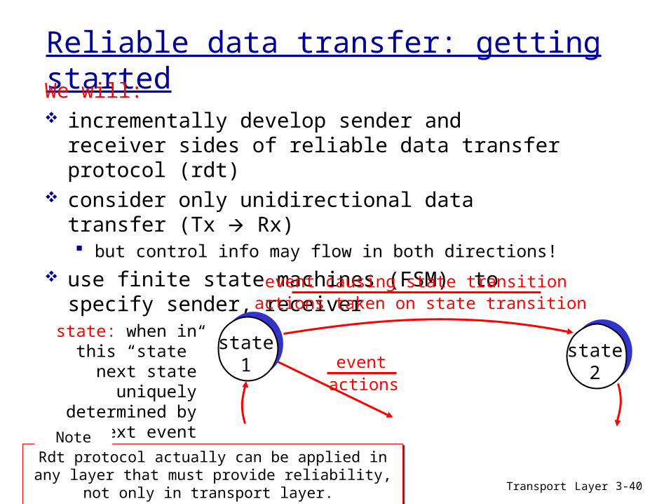
Reliable data transfer: getting startedWe will: incrementally develop sender and receiver sides of
reliable data transfer protocol (rdt) consider only unidirectional data transfer (Tx Rx)
but control info may flow in both directions! use finite state machines (FSM) to specify sender,
receiver
state1
state2
event causing state transitionactions taken on state transition
state: when in this “state” next state uniquely determined by next
event
eventactions
Rdt protocol actually can be applied in any layer that must provide reliability, not only in transport layer.
Rdt protocol actually can be applied in any layer that must provide reliability, not only in transport layer.
Note
Transport Layer 3-41
rdt1.0: reliable transfer over a reliable channel
The most simple case. It’s not realistic. underlying channel perfectly reliable
no bit errors no loss of PDUs
separate FSMs for sender, receiver: sender sends PDUs into underlying channel (to the below layer) receiver read data from underlying channel (from the below layer)
Wait for call from
above packet = make_pkt(data)udt_send(packet)
rdt_send(data)
extract (packet,data)deliver_data(data)
Wait for call from
below
rdt_rcv(packet)
sender (Tx) receiver (Rx)
In FSMs, PDUs are called packets.In FSMs, PDUs are called packets.Note

Transport Layer 3-42
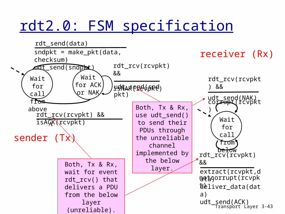
rdt2.0: channel with bit errors underlying channel may change bits in packet
checksum to detect bit errors the question: how to recover from errors.
acknowledgements (ACKs): receiver explicitly tells sender that pkt received OK
negative acknowledgements (NAKs): receiver explicitly tells sender that pkt had errors
sender retransmits pkt on receipt of NAK new mechanisms in rdt2.0 (beyond rdt1.0):
error detection receiver feedback: control PDUs (ACK,NAK) rcvrsender
Transport Layer 3-43
rdt2.0: FSM specification
Wait for call from
above
sndpkt = make_pkt(data, checksum)udt_send(sndpkt)
extract(rcvpkt,data)deliver_data(data)udt_send(ACK)
rdt_rcv(rcvpkt) && notcorrupt(rcvpkt)
rdt_rcv(rcvpkt) && isACK(rcvpkt)
udt_send(sndpkt)
rdt_rcv(rcvpkt) && isNAK(rcvpkt)
udt_send(NAK)
rdt_rcv(rcvpkt) && corrupt(rcvpkt)
Wait for ACK or
NAK
Wait for call from
belowsender (Tx)
receiver (Rx)rdt_send(data)
Both, Tx & Rx, use udt_send() to send their PDUs through
the unreliable channel
implemented by the below layer.
Both, Tx & Rx, wait for event rdt_rcv() that
delivers a PDU from the below layer (unreliable).
Transport Layer 3-44
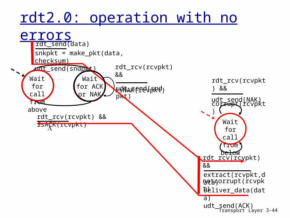
rdt2.0: operation with no errors
Wait for call from
above
snkpkt = make_pkt(data, checksum)udt_send(sndpkt)
extract(rcvpkt,data)deliver_data(data)udt_send(ACK)
rdt_rcv(rcvpkt) && notcorrupt(rcvpkt)
rdt_rcv(rcvpkt) && isACK(rcvpkt)
udt_send(sndpkt)
rdt_rcv(rcvpkt) && isNAK(rcvpkt)
udt_send(NAK)
rdt_rcv(rcvpkt) && corrupt(rcvpkt)
Wait for ACK or
NAK
Wait for call from
below
rdt_send(data)
Transport Layer 3-45
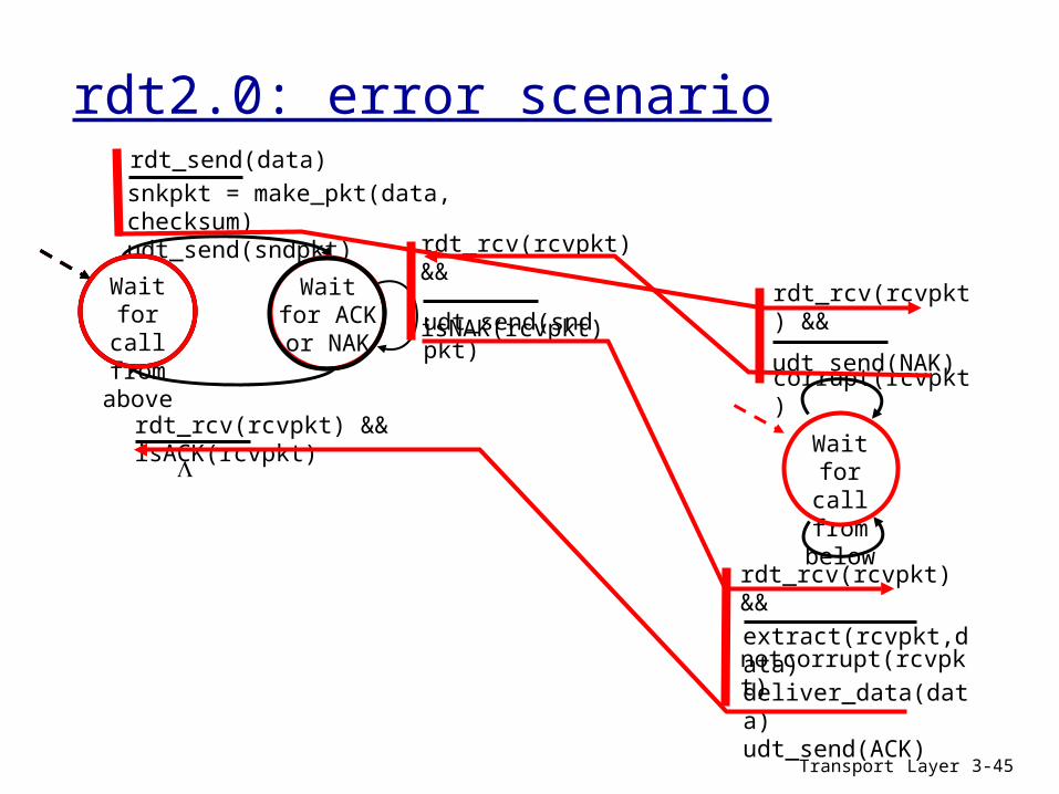
rdt2.0: error scenario
Wait for call
from above
snkpkt = make_pkt(data, checksum)udt_send(sndpkt)
extract(rcvpkt,data)deliver_data(data)udt_send(ACK)
rdt_rcv(rcvpkt) && notcorrupt(rcvpkt)
rdt_rcv(rcvpkt) && isACK(rcvpkt)
udt_send(sndpkt)
rdt_rcv(rcvpkt) && isNAK(rcvpkt)
udt_send(NAK)
rdt_rcv(rcvpkt) && corrupt(rcvpkt)
Wait for ACK or
NAK
Wait for call from
below
rdt_send(data)

Transport Layer 3-46
rdt2.0 serious fail
What happens if a control PDU (ACK or NAK) corrupted?
Tx doesn’t know if it has received an ACK or a NACK as the control PDU has errors!
Tx doesn’t know how data PDU arrived at Rx
can’t retransmit: possible duplicate
Handling duplicates: Tx retransmits current PDU if
control PDU (ACK/NAK) has errors
Tx adds sequence number in PCI to each PDU
Rx discards (doesn’t deliver up) duplicate PDUs
Tx sends one PDU, then waits for receiver response

Transport Layer 3-47
rdt2.1: sender, handles garbled ACK/NAKs
Wait for call 0 from
above
sndpkt = make_pkt(0, data, checksum)udt_send(sndpkt)
rdt_send(data)
Wait for ACK or NAK
0 udt_send(sndpkt)
rdt_rcv(rcvpkt) && ( corrupt(rcvpkt) ||isNAK(rcvpkt) )
sndpkt = make_pkt(1, data, checksum)udt_send(sndpkt)
rdt_send(data)
rdt_rcv(rcvpkt) && notcorrupt(rcvpkt) && isACK(rcvpkt)
udt_send(sndpkt)
rdt_rcv(rcvpkt) && ( corrupt(rcvpkt) ||isNAK(rcvpkt) )
rdt_rcv(rcvpkt) && notcorrupt(rcvpkt) && isACK(rcvpkt)
Wait for call 1 from
above
Wait for ACK or NAK
1

Transport Layer 3-48
rdt2.1: receiver, handles garbled ACK/NAKs
Wait for 0 from below
sndpkt = make_pkt(NAK, chksum)udt_send(sndpkt)
rdt_rcv(rcvpkt) && not corrupt(rcvpkt) && has_seq0(rcvpkt)
rdt_rcv(rcvpkt) && notcorrupt(rcvpkt) && has_seq1(rcvpkt)
extract(rcvpkt,data)deliver_data(data)sndpkt = make_pkt(ACK, chksum)udt_send(sndpkt)
Wait for 1 from below
rdt_rcv(rcvpkt) && notcorrupt(rcvpkt) && has_seq0(rcvpkt)
extract(rcvpkt,data)deliver_data(data)sndpkt = make_pkt(ACK, chksum)udt_send(sndpkt)
rdt_rcv(rcvpkt) && (corrupt(rcvpkt)
sndpkt = make_pkt(ACK, chksum)udt_send(sndpkt)
rdt_rcv(rcvpkt) && not corrupt(rcvpkt) && has_seq1(rcvpkt)
rdt_rcv(rcvpkt) && (corrupt(rcvpkt)
sndpkt = make_pkt(ACK, chksum)udt_send(sndpkt)
sndpkt = make_pkt(NAK, chksum)udt_send(sndpkt)
Transport Layer 3-49
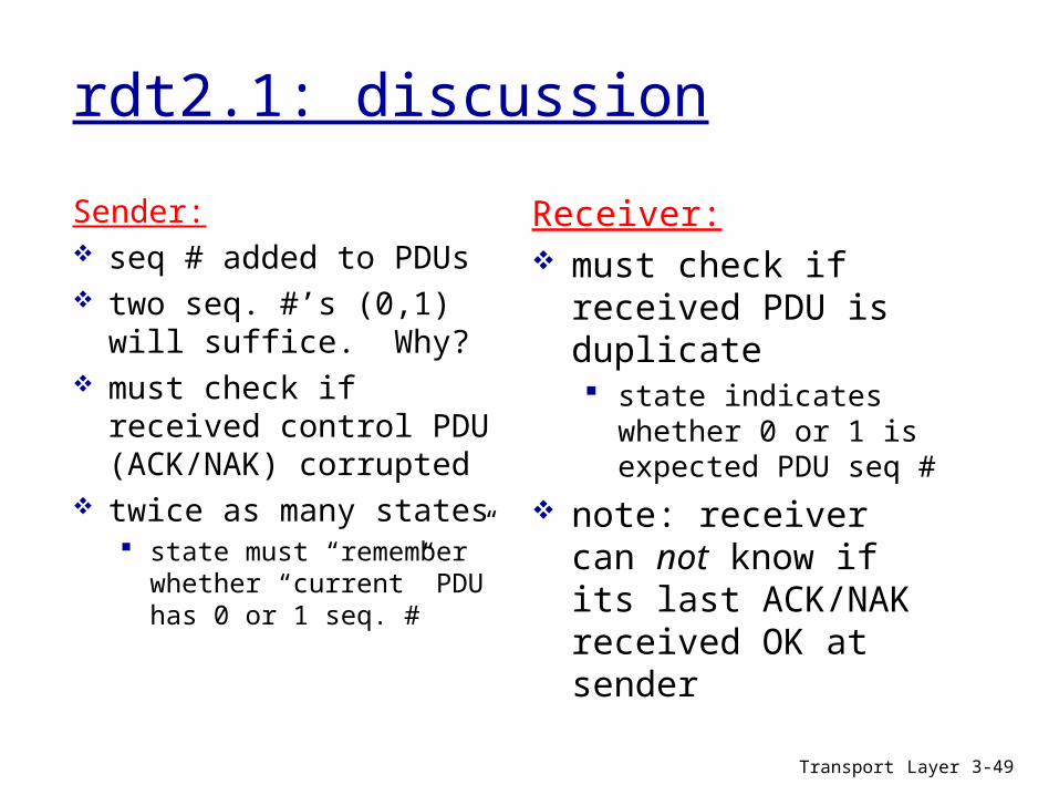
rdt2.1: discussion
Sender: seq # added to PDUs two seq. #’s (0,1) will
suffice. Why? must check if received
control PDU (ACK/NAK) corrupted
twice as many states state must “remember”
whether “current” PDU has 0 or 1 seq. #
Receiver: must check if received
PDU is duplicate state indicates whether 0 or
1 is expected PDU seq # note: receiver can not
know if its last ACK/NAK received OK at sender
Transport Layer 3-50
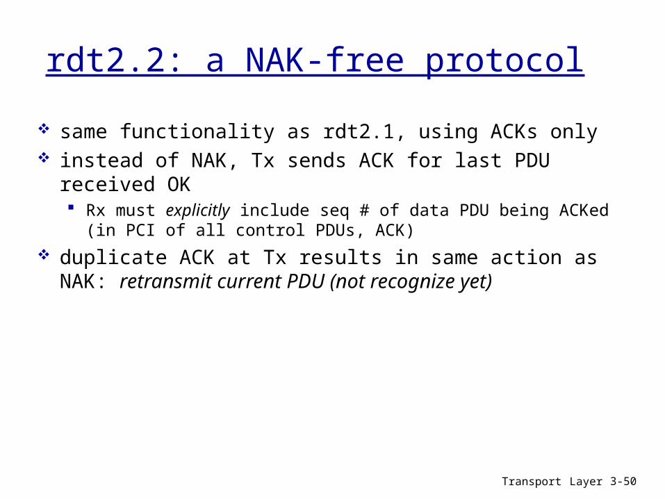
rdt2.2: a NAK-free protocol
same functionality as rdt2.1, using ACKs only instead of NAK, Tx sends ACK for last PDU received OK
Rx must explicitly include seq # of data PDU being ACKed (in PCI of all control PDUs, ACK)
duplicate ACK at Tx results in same action as NAK: retransmit current PDU (not recognize yet)
Transport Layer 3-51
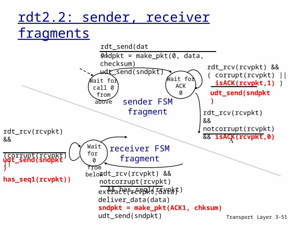
rdt2.2: sender, receiver fragments
Wait for call 0 from above
sndpkt = make_pkt(0, data, checksum)udt_send(sndpkt)
rdt_send(data)
udt_send(sndpkt)
rdt_rcv(rcvpkt) && ( corrupt(rcvpkt) || isACK(rcvpkt,1) )
rdt_rcv(rcvpkt) && notcorrupt(rcvpkt) && isACK(rcvpkt,0)
Wait for ACK
0
sender FSMfragment
rdt_rcv(rcvpkt) && notcorrupt(rcvpkt) && has_seq1(rcvpkt)
extract(rcvpkt,data)deliver_data(data)sndpkt = make_pkt(ACK1, chksum)udt_send(sndpkt)
Wait for 0 from below
rdt_rcv(rcvpkt) && (corrupt(rcvpkt) || has_seq1(rcvpkt))
udt_send(sndpkt)
receiver FSMfragment
Transport Layer 3-52
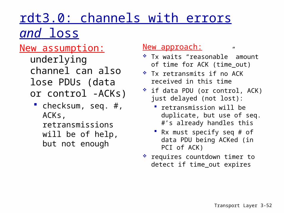
rdt3.0: channels with errors and loss
New assumption: underlying channel can also lose PDUs (data or control -ACKs) checksum, seq. #, ACKs,
retransmissions will be of help, but not enough
New approach: Tx waits “reasonable” amount of
time for ACK (time_out) Tx retransmits if no ACK received in
this time if data PDU (or control, ACK) just
delayed (not lost): retransmission will be
duplicate, but use of seq. #’s already handles this
Rx must specify seq # of data PDU being ACKed (in PCI of ACK)
requires countdown timer to detect if time_out expires

Transport Layer 3-53
rdt3.0 sender (Tx)
sndpkt = make_pkt(0, data, checksum)udt_send(sndpkt)start_timer
rdt_send(data)
Wait for
ACK0
rdt_rcv(rcvpkt) && ( corrupt(rcvpkt) ||isACK(rcvpkt,1) )
Wait for call 1 from
above
sndpkt = make_pkt(1, data, checksum)udt_send(sndpkt)start_timer
rdt_send(data)
rdt_rcv(rcvpkt) && notcorrupt(rcvpkt) && isACK(rcvpkt,0)
rdt_rcv(rcvpkt) && ( corrupt(rcvpkt) ||isACK(rcvpkt,0) )
rdt_rcv(rcvpkt) && notcorrupt(rcvpkt) && isACK(rcvpkt,1)
stop_timerstop_timer
udt_send(sndpkt)start_timer
timeout
udt_send(sndpkt)start_timer
timeout
rdt_rcv(rcvpkt)
Wait for call 0from
above
Wait for
ACK1
rdt_rcv(rcvpkt)
Design receiver FSM for the rdt3.0 protocol
Exercise
Transport Layer 3-54
rdt3.0 in action
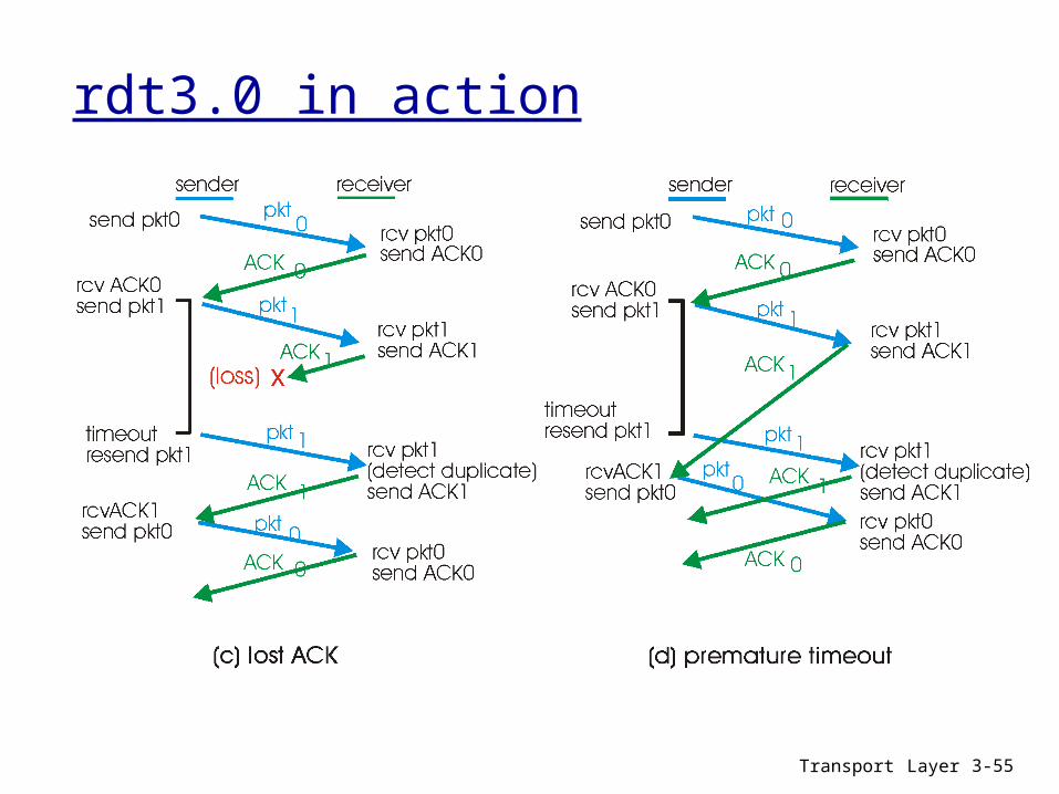
Transport Layer 3-55
rdt3.0 in action

Transport Layer 3-56
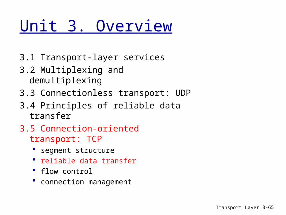
Unit 3. Overview
3.1 Transport-layer services3.2 Multiplexing and demultiplexing3.3 Connectionless transport: UDP3.4 Principles of reliable data transfer3.5 Connection-oriented transport: TCP
segment structure reliable data transfer flow control connection management

Transport Layer 3-57
TCP: Overview RFCs: 793, 1122, 1323, 2018, 2581
full duplex data: bi-directional data flow in
same connection MSS: maximum segment
size (UDs) connection-oriented:
handshaking (exchange of control msgs) inits sender, receiver state before data exchange
flow control: sender will not overwhelm
receiver
point-to-point: one sender, one receiver
reliable, in-order byte stream: no “message boundaries”
(A_PDUs) pipelined:
TCP congestion and flow control set window size (maximum PDUs # in-flight)
send & receive buffers
socketdoor
T C Psend buffer
T C Preceive buffer
socketdoor
segm ent
applicationwrites data
applicationreads data

Transport Layer 3-58
TCP segment structure (T_PDU)
source port # dest port #
32 bits
applicationdata
(variable length)
sequence number
acknowledgement numberReceive window
Urg data pnterchecksum
FSRPAUheadlen
notused
Options (variable length)
URG: urgent data (generally not used)
ACK: ACK #valid
PSH: push data now(generally not used)
RST, SYN, FIN:connection estab(setup, teardown
commands)
# bytes rcvr willingto accept
countingby bytes of data(not segments!)
Internetchecksum
(as in UDP)
T_PCI
T_UD

Transport Layer 3-59
TCP seq. #’s and ACKs (I)Sequence number: Assigned number for the first byte of a TCP segment that is sent to the other
peer entity. Initial value is set in a random way by each entity peer when connection is
initiated. Increased when segments containing PDUs are sent.ACK number: Points out the sequence number which is expected to be received by the
other peer entity. All the previous bytes are acknowledged (cumulative ACK ).
Q: How does the rcv manage disordered segments? A: TCP specification leaves it to the implementer.
Transport Layer 3-60
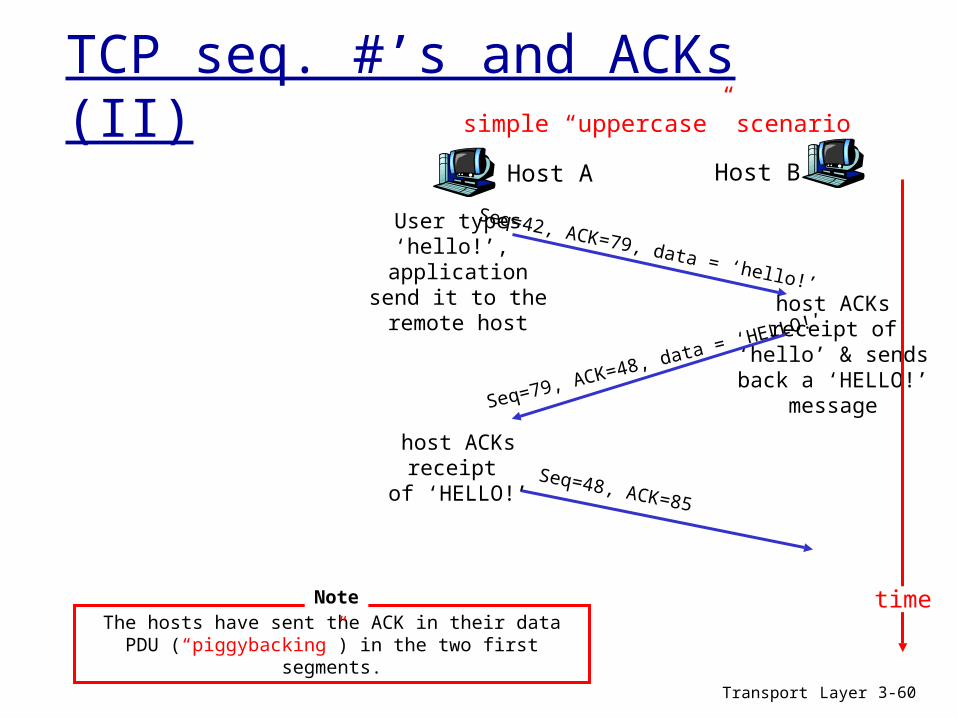
TCP seq. #’s and ACKs (II)Host A Host B
Seq=42, ACK=79, data = ‘hello!’
Seq=79, ACK=48, data = ‘HELLO!’
Seq=48, ACK=85
User types‘hello!’,
applicationsend it to theremote host
host ACKsreceipt
of ‘HELLO!’
host ACKsreceipt of
‘hello’ & sendsback a ‘HELLO!’
message
time
simple “uppercase” scenario
The hosts have sent the ACK in their data PDU (“piggybacking”) in the two first segments.
Note
Transport Layer 3-61
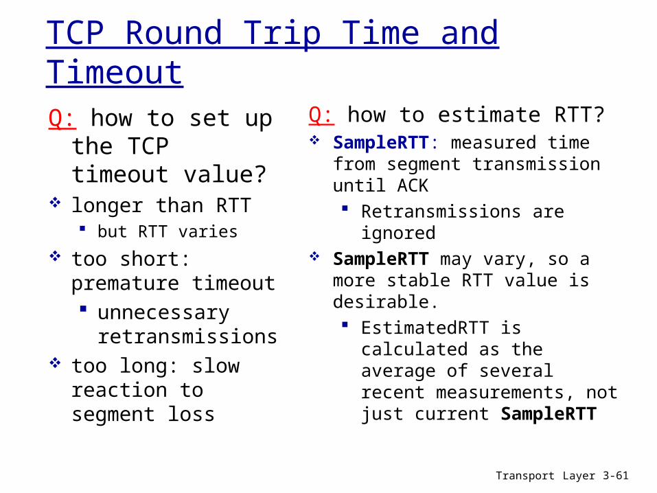
TCP Round Trip Time and Timeout
Q: how to set up the TCP timeout value?
longer than RTT but RTT varies
too short: premature timeout unnecessary
retransmissions too long: slow reaction
to segment loss
Q: how to estimate RTT? SampleRTT: measured time from
segment transmission until ACK Retransmissions are ignored
SampleRTT may vary, so a more stable RTT value is desirable. EstimatedRTT is calculated as
the average of several recent measurements, not just current SampleRTT

Transport Layer 3-62
TCP Round Trip Time and Timeout
EstimatedRTT = (1- )*EstimatedRTT + *SampleRTT
Exponential weighted moving average influence of past sample decreases exponentially fast typical value: = 0.125

Transport Layer 3-63
Example RTT estimation:RTT: gaia.cs.umass.edu to fantasia.eurecom.fr
100
150
200
250
300
350
1 8 15 22 29 36 43 50 57 64 71 78 85 92 99 106
time (seconnds)
RTT
(mill
isec
onds
)
SampleRTT Estimated RTT

Transport Layer 3-64
TCP Round Trip Time and Timeout
Setting the timeout EstimatedRTT plus “safety margin”
large variation in EstimatedRTT -> larger safety margin A first estimation of SampleRTT deviation from EstimatedRTT:
TimeoutInterval = EstimatedRTT + 4*DevRTT
DevRTT = (1-)*DevRTT + *|SampleRTT-EstimatedRTT|
(typically, = 0.25)
Then set timeout interval:
Transport Layer 3-65
Unit 3. Overview
3.1 Transport-layer services3.2 Multiplexing and demultiplexing3.3 Connectionless transport: UDP3.4 Principles of reliable data transfer3.5 Connection-oriented transport: TCP
segment structure reliable data transfer flow control connection management

Transport Layer 3-66
TCP reliable data transfer
TCP creates rdt service over IP’s unreliable service
pipelined segments, several segments “in-flight”
cumulative acks TCP uses single
retransmission timer
retransmissions are triggered by: timeout events duplicate acks
Initially, a simplified TCP sender is considered : ignores duplicate acks ignores flow control,
congestion control
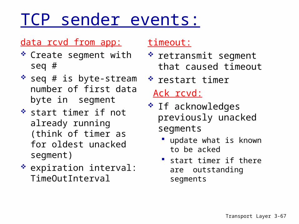
Transport Layer 3-67
TCP sender events:data rcvd from app: Create segment with seq
# seq # is byte-stream
number of first data byte in segment
start timer if not already running (think of timer as for oldest unacked segment)
expiration interval: TimeOutInterval
timeout: retransmit segment that
caused timeout restart timer Ack rcvd: If acknowledges
previously unacked segments update what is known to be
acked start timer if there are
outstanding segments

Transport Layer 3-68
TCP sender (simplified) NextSeqNum = InitialSeqNum SendBase = InitialSeqNum while (true) { switch(event)
event: data received from application above create TCP segment with data and sequence number NextSeqNum if (timer currently not running) start timer pass segment to IP /* Below layer, unreliable, sends segment to Rx */ NextSeqNum = NextSeqNum + length(data)
event: timer timeout retransmit not-yet-acknowledged segment with smallest sequence number start timer
event: ACK received, with ACK field value of y if (y > SendBase) { /* If not-yet-adcknowledged data are being acknowleged */ SendBase = y /* Update indicator not-yet-acknowledged data*/
stop timer if (NextSeqNum > SendBase) /* There are currently not-yet-acknowledged data */ start timer } } /* end of infinite loop */
Every data byte with seq# less than SendBase is acknowledged cumulatively. The ones that have greater or equal seq # are not yet acknowledged.
NextSeqNum points to “not sent” data.
Rx sends ack for all data with seq # less than y.
Transport Layer 3-69
TCP: retransmission scenarios (I)
Host A
Seq=100, 20 bytes data
ACK=100
timepremature timeout scenario
Host B
Seq=92, 8 bytes data
ACK=120
Seq=92, 8 bytes data
Seq=
92 ti
meo
ut
ACK=120
Host A
Seq=92, 8 bytes data
ACK=100
loss
timeo
ut
lost ACK scenario
Host B
X
Seq=92, 8 bytes data
ACK=100
time
Seq=
92 ti
meo
utSendBase
= 100
SendBase= 120
SendBase= 120
SendBase= 100

Transport Layer 3-70
TCP retransmission scenarios (II)Host A
Seq=92, 8 bytes data
ACK=100
loss
timeo
ut
Cumulative ACK scenario
Host B
X
Seq=100, 20 bytes data
ACK=120
time
SendBase = 120
Doesn’t expire
Tim
e_ou
t Sec
=92
Timer with the “recommended” timeout would have expired before ACK=120 arrived.So, on a retransmission only, Tx will use a timeout that is longer that the recommended one (double for first retransmission, quadruple for second one, ….), which make it easy to produce cumulative ACKs.
Tim
e_ou
t Sec
=92

Transport Layer 3-71
TCP ACK generation [RFC 1122, RFC 2581]
Event at Receiver
Arrival of in-order segment withexpected seq #. All data up toexpected seq # already ACKed
Arrival of in-order segment withexpected seq #. One other segment has ACK pending
Arrival of out-of-order segmenthigher-than-expect seq. # .Gap detected
Arrival of segment that partially or completely fills gap
TCP Receiver action
Delayed ACK. Wait up to 500msfor next segment. If no next segment,send ACK
Immediately send single cumulative ACK, ACKing both in-order segments
Immediately send duplicate ACK, indicating seq. # of next expected byte
Immediate send ACK, that corresponds to the arrived segment
Transport Layer 3-72
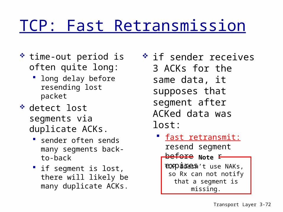
TCP: Fast Retransmission
time-out period is often quite long: long delay before resending
lost packet detect lost segments via
duplicate ACKs. sender often sends many
segments back-to-back if segment is lost, there will
likely be many duplicate ACKs.
if sender receives 3 ACKs for the same data, it supposes that segment after ACKed data was lost: fast retransmit: resend
segment before timer expires
TCP doesn’t use NAKs, so Rx can not notify that a segment is
missing.
Note
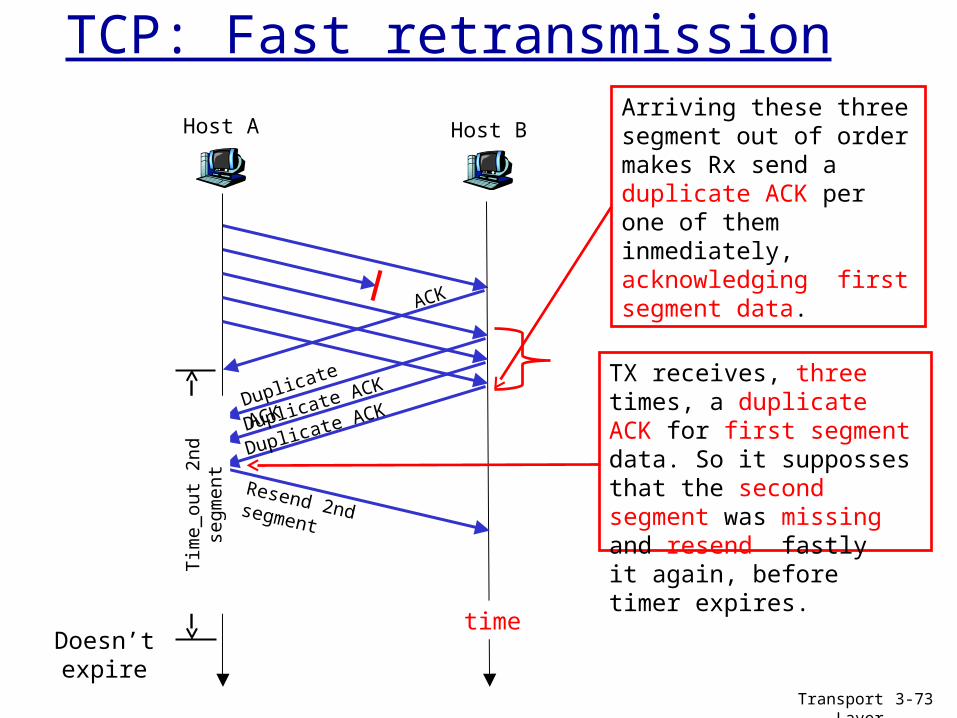
Host A Host B
Resend 2nd segment
time
Tim
e_ou
t 2nd
seg
men
t
Doesn’t expire
TCP: Fast retransmission
TX receives, three times, a duplicate ACK for first segment data. So it supposses that the second segment was missing and resend fastly it again, before timer expires.
Arriving these three segment out of order makes Rx send a duplicate ACK per one of them inmediately, acknowledging first segment data.
ACK
Duplicate ACK
Duplicate ACK
Duplicate ACK
Transport Layer
3-73

Transport Layer 3-74
event: ACK received, with ACK field value of y if (y > SendBase) { /* If not-yet-adcknowledged data are being acknowleged */
SendBase = y /* Update indicator not-yet-acknowledged data*/
stop timer if (NextSeqNum > SendBase) /*There are currently not-yet-acknowledged segments*/
start timer } else { /*It’s a duplicated ACK for already acknowledged segment*/
increment count of dup ACKs received for y if (count of dup ACKs received for y = 3) { resend segment with sequence number y /*Fast retransmission*/
start timer }
TCP: Fast retransmitThis is the ACK reception event in the simplified TCP Tx.
This part is for giving sender TCP more “intelligence” and knows to react if receives 3 duplicated ACKs, by doing fast retransmission for not-already acknowledged segment.

Transport Layer 3-75
Unit 3. Overview
3.1 Transport-layer services3.2 Multiplexing and demultiplexing3.3 Connectionless transport: UDP3.4 Principles of reliable data transfer3.5 Connection-oriented transport: TCP
segment structure reliable data transfer flow control connection management

Transport Layer 3-76
TCP Flow Control receive side of TCP
connection has a receive buffer:
speed-matching service: matching the sender’s rate to the receiving app’s drain rate
app process may be slow at reading from buffer
sender shall not overflowreceiver’s buffer by
transmitting too much, too fast
flow control
RcvBuffer
RcvWindow
Free space in TCP buffer
TCP data in buffer, waiting for being read by
app
Data from IP
Application process
Variable size
Fixed size
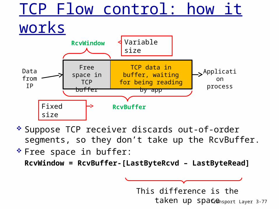
Transport Layer 3-77
TCP Flow control: how it works
Suppose TCP receiver discards out-of-order segments, so they don’t take up the RcvBuffer.
Free space in buffer: RcvWindow = RcvBuffer-[LastByteRcvd – LastByteRead]
RcvBuffer
RcvWindow
Free space in TCP buffer
TCP data in buffer, waiting for being reading
by app
Data from IP
Application process
Variable size
Fixed size
This difference is the taken up space

Transport Layer 3-78
TCP Flow control: how it works
rcvr announces free space in buffer by including value of RcvWindow in header segments (T_PCI)
sender limits unACKed data to RcvWindow Guarantees RcvBuffer is not overflown
RcvBuffer
RcvWindow
Free space in TCP buffer
TCP data in buffer, waiting for being reading
by app
Data from IP
Application process
Variable size
Fixed size
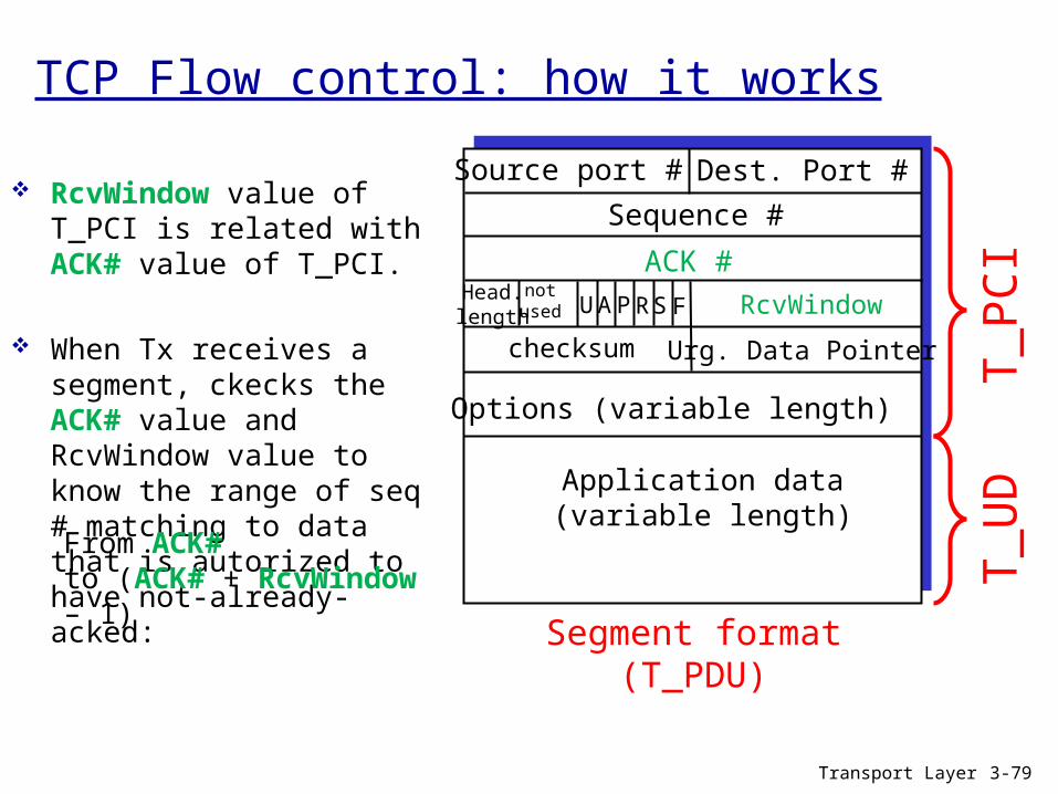
RcvWindow value of T_PCI is related with ACK# value of T_PCI.
When Tx receives a segment, ckecks the ACK# value and RcvWindow value to know the range of seq # matching to data that is autorized to have not-already-acked:
Transport Layer 3-79
From ACK#to (ACK# + RcvWindow – 1)
Source port # Dest. Port #
Application data(variable length)
Sequence #
ACK #RcvWindow
Urg. Data Pointerchecksum
FSRPAUHead.length
notused
Options (variable length)
T_PC
IT_
UD
Segment format (T_PDU)
TCP Flow control: how it works
Transport Layer 3-80
Unit 3. Overview
3.1 Transport-layer services3.2 Multiplexing and demultiplexing3.3 Connectionless transport: UDP3.4 Principles of reliable data transfer3.5 Connection-oriented transport: TCP
segment structure reliable data transfer flow control connection management
TCP Connection Management
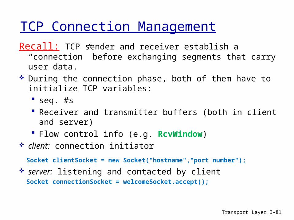
Recall: TCP sender and receiver establish a “connection” before exchanging segments that carry user data.
During the connection phase, both of them have to initialize TCP variables: seq. #s Receiver and transmitter buffers (both in client and server) Flow control info (e.g. RcvWindow)
client: connection initiator
Socket clientSocket = new Socket("hostname","port number"); server: listening and contacted by client Socket connectionSocket = welcomeSocket.accept();
Transport Layer 3-81

client
SYN, SeqNum=client_isn(not carrying ACK neither DATA)
server
SYN, SeqNum=server_isn, ACK=client_isn+1 (not carrying DATA)
SeqNum=client_isn+1, ACK=server_isn+1 (not usually carryingDATA)
Three way handshake
timetime
TCP Connection Management
Transport Layer
3-82
In TCP_PDUs flow, if a flag is active, it is indicated in the labels (except ACK, which is implicit).
Note

Three-way handshake:Step 1: Client sets up initial values for all TCP variables (buffers, initial sequence number,
etc.)- Then, it sends a SYN segment to the server: Doesn’t carry data. Specifies the initial seq # (client_isn). Carries SYN bit set to one. It is considered as the first byte of the data stream of the
TCP connection.Step 2: when receiving SYN segment, server initialize TCP buffers and variables and
sends a (SYN-ACK segment) to the TCP client:
Has the same characteristics of client SYN segment but specifying the server initial seq # (server_isn).
Acknowledges the client’s SYN segment.Step 3: Client receives the SYN-ACK segment from the server and responds sending an ACK
segment: acknowledges the server’s SYN-ACK segment. May content user data, although it ‘s not usual.
Transporte 3-83
TCP Connection Management: Establishment

Transport Layer 3-84
TCP Connection Management: Closing a connection
FIN segment has FIN bit set to 1. It is the last byte of the TCP connection data stream.
TCP entity that sends a FIN segment can not send data anymore but can receive.
client
FIN
server
ACK
ACK
FIN
socketClient.close();
socketConnection.close();
Closed connection
timed
wai
t
Both client and server may start connection close.
Note

Transport Layer 3-85
Step 1: client app closes connection by socketClient.close(); sends a TCP FIN segment to server.
Step 2: server receives FIN, replies with ACK.
Step 3: server app closes connection by socketConnection.close(); sends FIN to client.
Step 4: client receives FIN, replies with ACK.
Enters “timed wait” - will respond with ACK to received FINs
When “timed wait” expires, TCP client considers the connection is closed (releasing buffers and others resources related to the connection).
Step 5: server receives ACK. Connection closed (releasing buffers…).
TCP Connection Management: Closing a connection

Transport Layer
3-86
TCP Connection Management: Closing a connection
Previous steps with some minor modifications are the same to close the connection if: Server takes the lead to close the connection and run socketConexion.close();
Both client and server, decide, simultaneously, to close the connection and run at the same time socketCliente.close(); and socketConexion.close();
Connections have to be closed inmediately when a RST segment is received (RST bit set to 1). RESET segment is sent only in some special cases and it is not the usual way to close the connection.

Transport Layer
3-87
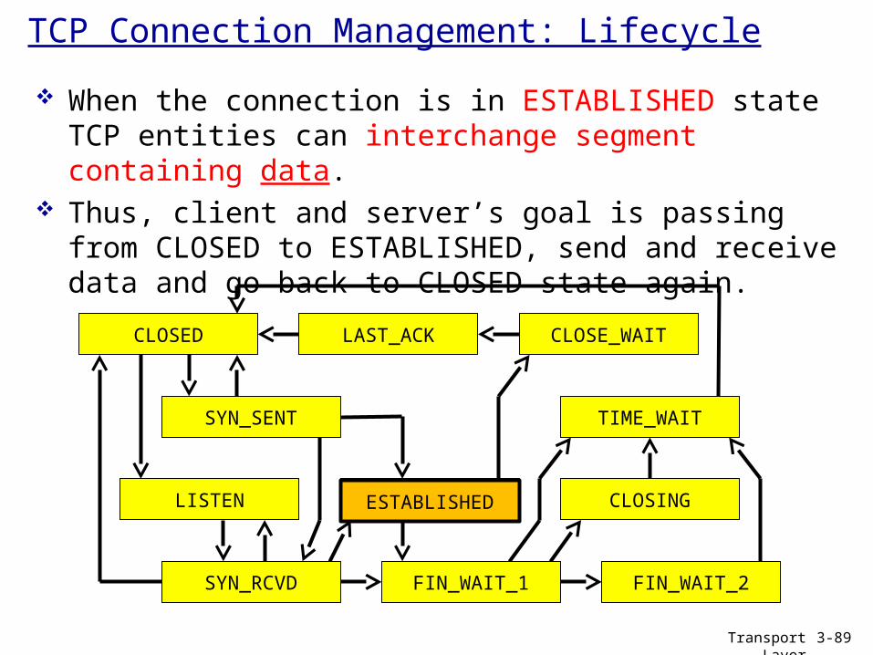
TCP Connection Management: Lifecycle
CLOSING
LAST_ACK CLOSE_WAIT
ESTABLISHEDLISTEN
FIN_WAIT_2
TIME_WAIT
FIN_WAIT_1SYN_RCVD
SYN_SENT
CLOSED
Life of a TCP connection: It is the sequence of TCP states of a TCP connection.
The next state machine shows 11 posible states and the diferent transitions among states.

Transport Layer
3-88
TCP Connection Management: Lifecycle
CLOSING
LAST_ACK CLOSE_WAIT
ESTABLISHEDLISTEN
FIN_WAIT_2
TIME_WAIT
FIN_WAIT_1SYN_RCVD
SYN_SENT
CLOSED
CLOSED is a fictitious state. It is the connection state before creating it, and after closing it completely. In this state, the connection doesn’t exist yet or has already stopped existing.
CLOSED is the initial and the final state of a connection
CLOSED
Transport Layer
3-89
TCP Connection Management: Lifecycle
CLOSING
LAST_ACK CLOSE_WAIT
ESTABLISHEDLISTEN
FIN_WAIT_2
TIME_WAIT
FIN_WAIT_1SYN_RCVD
SYN_SENT
CLOSED
When the connection is in ESTABLISHED state TCP entities can interchange segment containing data.
Thus, client and server’s goal is passing from CLOSED to ESTABLISHED, send and receive data and go back to CLOSED state again.
ESTABLISHED

Transport Layer
3-90
TCP Connection Management: Lifecycle
In green, the transitions of a typical client lifecycle. In red, the transitions of a typical server lifecycle. Black transitions are posible but not usual.
CLOSING
LAST_ACK CLOSE_WAIT
ESTABLISHEDLISTEN
FIN_WAIT_2
TIME_WAIT
FIN_WAIT_1SYN_RCVD
SYN_SENT
CLOSED

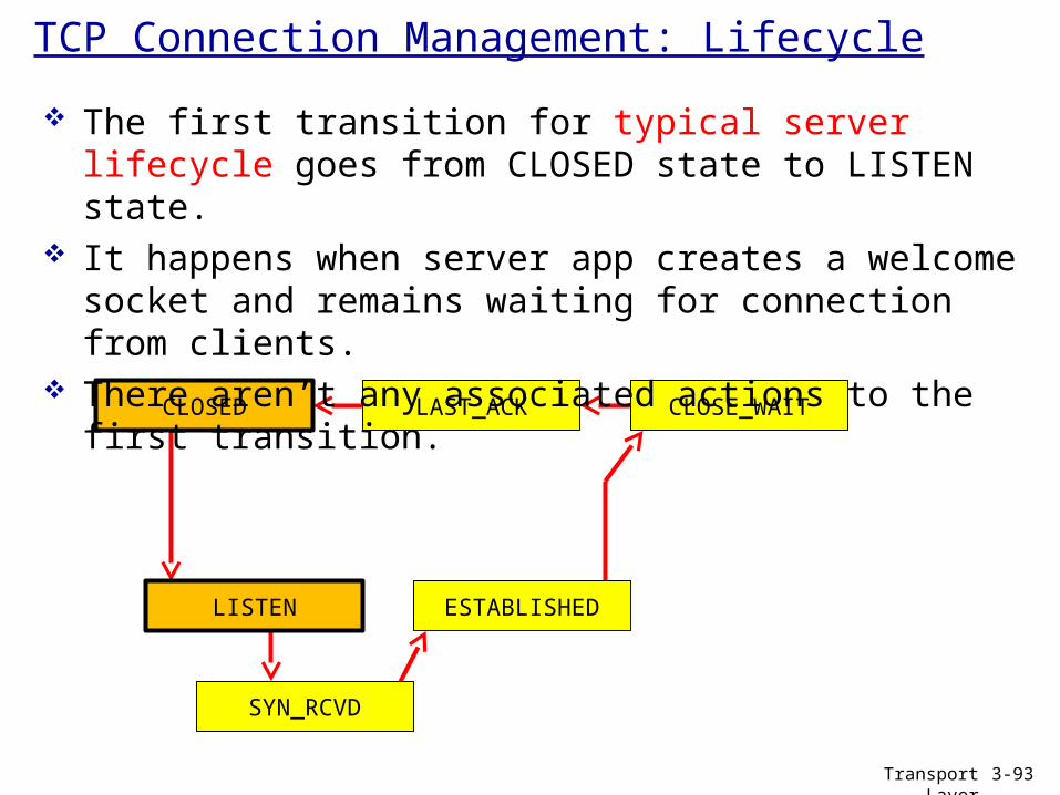
TCP Connection Management: Lifecycle
The first transition in a typical client clifecycle goes from CLOSED state to SYN_SENT state.
It happens when a “Client app starts a connection”. Event is issued.
“Send SYN segment” action is associated to it.
ESTABLISHED
FIN_WAIT_2
TIME_WAIT
FIN_WAIT_1
SYN_SENT
CLOSED
Transport Layer 3-91

TCP Connection Management: Lifecycle
Possible combinations “event/action” of the transitions of a typical client lifecycle.
ESTABLISHED FIN_WAIT_2
TIME_WAIT
FIN_WAIT_1
SYN_SENT
CLOSED
Transporte 3-92
Client app initiates a connection
Send SYN segment
SYN-ACK segment is received
Send ACK for SYN
Pass twice MSL time
Send nothing
ACK for FIN is received
Send nothing
App initiates close connection
Send FIN segment
Send ACK for FIN
FIN segment is received
TCP Connection Management: Lifecycle
LAST_ACK CLOSE_WAIT
ESTABLISHEDLISTEN
SYN_RCVD
CLOSED
Transport Layer
3-93
The first transition for typical server lifecycle goes from CLOSED state to LISTEN state.
It happens when server app creates a welcome socket and remains waiting for connection from clients.
There aren’t any associated actions to the first transition.

TCP Connection Management: Lifecycle
Possible combinations “event/action” of the transitions of a typical server lifecycle.
CLOSED
Transport Layer
3-94
Server app creates welcome socket
SYN segment is received
Send ACK-SYN segment
ACK for FIN is received
Send nothing
Send ACK for FIN
FIN segment is received
LAST_ACK
CLOSE_WAIT
ESTABLISHED
LISTEN
SYN_RCVD
Send nothing
ACK for SYN is received
Send nothing
App initiates close connection
Send FIN segment
Transport Layer 3-95
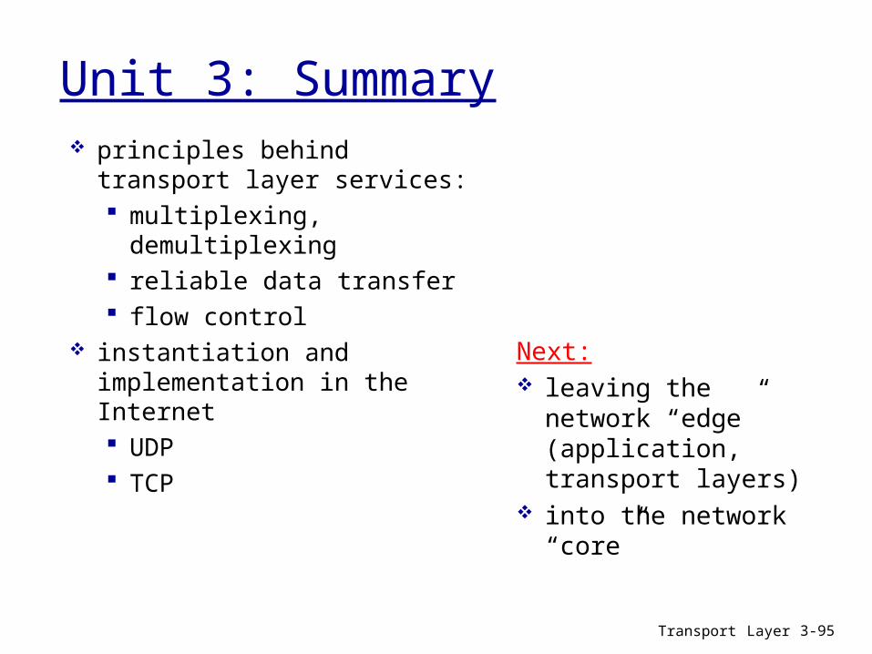
Unit 3: Summary principles behind transport
layer services: multiplexing, demultiplexing reliable data transfer flow control
instantiation and implementation in the Internet UDP TCP
Next: leaving the network
“edge” (application, transport layers)
into the network “core”

PROBLEMS AND EXERCISES
Computer Networking – Unit 3: Transport layer
Departamento deTecnología Electrónica
Transport Layer 96

Pr1: port numbers
Transport layer 2-97
Suppose that client A initiates a TCP connection to a Web server called S. Naerly simultaneously, client B also initiates a TCP connection to S.
a) Indicate possible source and destination port numbers for:1. Segments sent from A to S
2. Segments sent from B to S
3. Segments sent from S to A
4. Segments sent from S to B
b) If A and B are in diferent hosts, could source port number from A to S be the same that from B to S?
c) What happens if client process A and B are in the same host?

Pr2: port numbers
Transport Layer 2-98
Look at the connections that the clients have initiated with the Web server and answer the questions:
P1
ClientIP: A
P1P2P4
Web ServerIP: C
SP: 9157DP: 80
SP: 9157DP: 80
P5 P6 P3
D-IP: CS-IP: A
D-IP: CS-IP: B
SP: 5775DP: 80
D-IP: CS-IP: B
client IP: B
SP = Source port #DP = Destination port #S-IP = Source IP addressD-IP = Destination IP address

Pr2: port numbers (II)
Transport Layer
3-99
What are the source and destination port number values in the segments flowing from the server to the clients’ processes?
What are the IP addresses (source and destination) of N_PDUs carrying these transport-layer segments?

Pr3: checksum
Transport Layer
3-100
UDP and TCP use 1s complement for their checksums. Suppose you have the following three 16-bit words:
1110000001010010 1101010100101111 0010101110101111
What is the 1s complement of the sum of these 16-bit words? Receiver adds the three words to the received checksum. If the
result of the addition, in binary, contains some zero, the receiver realizes there is some error in some bit, is it right?
Is it possible that a 1-bit error will go undetected? Propose a particular example for a non-detectable error.

Pr4: Channel utilization
Transport Layer
3-101
Pipeline protocols improve the performance of stop-and-wait protocols.
Suppose a Tx and a Rx with a 1Gbps link, 30ms RTT, 1500 bytes PDUs and header size equal to zero (negligible size in comparison to the data size).
How many data PDUs have to be “in-flight” for a channel utilization of 95%?

Pr5: Control over T_PDU content
Transport Layer
3-102
It was said that an application may choose UDP for a transport protocol as UDP offers finer application control (than TCP) of what data is sent in a segment, and when.
a) Why does an application have more control of what data is sent in a segment?
b) Why does an application have more control on when the segment is sent?
Pr6
Transport Layer
3-103
Suppose a client application protocol which is sending an only PDU of 1000 bytes, using transport reliable service. Server application replies with a 100 bytes PDU.
Make a diagram of TCP_PDU flow. Label active flags, point out seq numbers, ACK numbers, and the number of bytes of the TCP_DU. Also point out the size (bytes) of every TCP_PDU. Suppose there are no options for TCP, and initial sequence numbers (ISN) of 1000 for the client, and 3000 for the server.

Pr7: MSS
Transport Layer
3-104
Consider transferring an enormous file of L bytes from Host A to Host B. Assume a MSS of 536 bytes.
a) What is the maximum value of L, so that TCP sequence numbers are run out of? Recall that the TCP sequence number field has 4 bytes.
Note: MSS is the maximum size of user data carried by any segment in a TCP connection. In SYN segment, using TCP options header, each TCP entity informs the other about MSS. The smaller is used.
Pr7: MSS (II)
Transporte 3-105
b) For the value of L obtained in (a), how long does it takes to transmit the file?
Suppose that a total of 66 bytes of transport, network, and data-link header are added to each segment. The packet is sent out over a 155 Mbpslink. Ignore flow control and congestion control so A can pump out the segments back to back and continuously.
Pr8.
Transporte 3-106
Suppose that a client application protocol is sending an only PDU of 100 bytes using the reliable transport service on the internet. Server app replies with a 100-byte PDU.
Make a diagram of TCP_PDU flow. Label active flags, point out seq numbers, ACK numbers, and the number of bytes of the TCP_DU. Also point out the size (bytes) of every TCP_PDU. Suppose there are no options for TCP, and initial sequence numbers (ISN) are 0 at both client and server. MSS is 536.

Pr9: seq # and ACK
Transport Layer
3-107
Host A and B are using a TCP connection. Host B has already received from A bytes up to byte 126. Then, Host A sends two back-to-back segments to Host B. Both segments have 70 and 50 bytes of data, respectively. In the first segment, the sequence number is 127, the source port number is 302, and the destination port number is 80. Host B sends an acknowledgement whenever it receives a segment from Host A.
• In the second segment sent from Host A to B, which are the sequence number, source port number, and destination port number?
• Consider that the first segment arrives before the second segment. For the acknowledgement of the first arriving segment, which is the acknowledgment number, the source port number, and the destination port number?

Pr9: seq # and ACK (II)
Transport Layer
3-108
c) Now, consider that the first segment arrives before the second segment. For the acknowledgement of the first arriving segment, which is the acknowledgment number, the source port number, and the destination port number?
d) Suppose the two segments sent by A arrive in order at B. The first acknowledgement is lost and the second acknowledgement arrives after the first timeout interval. Draw a time diagram, showing all the segments and acknowledgements that were sent. (Assume there is no additional packet loss.) For each segment in your figure, provide the sequence number and the number of bytes of data; for each acknowledgement that you add, provide the acknowledgement number.
Pr10: TCP flow control
Transport Layer
3-109
Host A and B are directly connected with a 100 Mbps link. There is a TCP connection between both hosts. Host A is
sending an enormous file over this connection to Host B. Host A can send its application data into its TCP socket at a rate
as high as 120 Mbps Host B can read out of its TCP receive buffer at a maximum rate
of 60 Mbps. Describe the effect of TCP flow control on host A’s application
layer rate in sending data through its TCP socket.
P11: estimated RTT
Transport Layer
3-110
We discussed about TCP needs to estimate a value for RTT, in order to know how long it has to wait for an ACK.
To estimate the RTT, TCP uses SampleRTT values. SampleRTT is the time between a segment sending and the arrival of its ACK.
However, TCP does not use the SampleRTT associated to the retransmitted segments.
Why do you think TCP avoids measuring the SampleRTT for retransmitted segments?
Pr12: variables in pipelining
Transport Layer
3-111
What is the relationship between the variable SendBase of TCP transmitter and the variable LastByteRcvd of TCP receiver?

Pr13: variables in pipelining
Transport Layer
3-112
What is the relationship between the variable LastByteRcvd of TCP receiver and the variable y of TCP sender?
Pr14: fast retransmission
Transport Layer
3-113
TCP waits until it has received three duplicate ACKs before performing a fast retransmission.
When receiving three duplicate ACKs for a segment, TCP does a fast retransmission of the segment, as it is supposed lost. Retransmission does not waiting for timer expiring.
Why do you think the TCP designers chose not to perform a fast retransmission after the first duplicate ACK for a segment is received?

Pr15: flow control
Transport Layer 3-114
Host A is sending an huge file to Host B over a TCP connection. Over this connection, no packet is loss and timers never expire. Transmission rate of the link connecting Host A to the Internet is R bps. Suppose that the process in Host A is capable of sending data into its
TCP socket at a rate of S bps, where S = 10·R. Furthermore, suppose that the TCP receiving buffer is large enough to
hold the entire file. The sender’s buffer can hold only one percent of the file.
What would prevent the process in Host A from continuously passing data to its TCP socket at rate S bps? TCP flow control? TCP congestion control? Or anything else? Discuss it.


