
Voltage grid support of DFIG wind turbines during grid faults
Gabriele MichalkeUniversity of Technology Darmstadt, Germany
Anca D. Hansen Risø National Laboratory, Denmark
EWEC Milan 7-10 May 2007

2
Outline
• Background
• DFIG wind turbine – modelling, control issues in case of grid faults:
• Drive train and pitch control system• DFIG system control and protection
• DFIG wind turbine – voltage grid support control
• Power transmission system test model
• Case study - simulation results
• Conclusions

3
Background
• Projects:• Ph.D project ”Variable Speed Wind Turbines - Modelling, Control and Impact on
Power Systems” funded by ”Stiftung Energieforschung Baden-Württemberg”• ”Simulation platform to model, optimise and design wind turbines” – funded by
Danish Energy Agency
• Participants:• Darmstadt Technical University• Risø National Laboratory• Aalborg Technical University
• Overall goal: • Wind farms interaction with the power system during grid faults• Advanced control design of wind farms according to the new grid codes
• Focus in this presentation: • Voltage grid support of DFIG wind turbines during grid faults

4
DFIG wind turbine – modelling, control issues in case of grid faults:
Crowbar
DFIG
~=
~ ~ ~
Power converter control
refQrefP
Control mode :• normal operation• fault operation
~=
RSC GSC
Fault detection
Drive train with gearbox
Wind turbine
Pitch angle control
DFIG system – control and protection
Aerodynamics
k
c

5
Drive train and pitch control system
ngear
J rot
Trot
J gen
Tgenc
k
• 2 mass mechanical model
eqosc J
kf
2
1
gengearrot
gengearroteq JnJ
JnJJ
2
2
Free – free frequency:
Equivalent inertia:
• Pitch control system
+
-
ref
ref
Gain schedullingKPI
+
- servoT
1
dt
d
s
1PI
Pitch angle controls the speed
Prevent over-speed both in: - normal operations - grid faults operations
Rate of change limitation important during grid faults

6
DFIG system control (normal operation)
ACDC AC
DC
RSC GSC
Power converter
PI PI PI PI dcU
GSCQ
DCrefUGSC
refQ
gridP
gridQ
gridrefP
gridrefQ
Slow control (power)
Power converter control • RSC controls Pgrid and Qgrid independently!• GSC controls UDC and QGSC=0 !
Reference signals:• Active power for RSC is defined by
MPT:
P
MPT
Maximum power tracking point
gridrefP
gridrefPPI PI PI
RSCqrefI RSC
drefI GSCqrefI GSC
drefI
RSCdIRSC
qI GSCdI
GSCqI
Fast control (current)
PI
• DC voltage is set to constant value
• GSC is reactive neutral
• Reactive power for RSC - certain
value or zero

7
DFIG system control and protection during grid faults
Power converter is very sensitive to grid faults !!!• Protection system monitors DFIG signals • Crowbar protection:
external rotor impedance
Severe grid faults triggers crowbar:• RSC disabled• DFIG behaves as SCIG• GSC can be used as a STATCOM
Damping controller
-1 -0.5 0 0.5 1 1.5 2 2.5 3-3
-2
-1
0
1
2
3
Speed [p.u.]
Ele
ctro
ma
gn
etic
to
rqu
e [
p.u
.] crowbarcrowbarcrowbar RRR 321
• Increased crowbar: improved dynamic stability of the generator reduces reactive power demand
New grid codes require:• Fault ride-through capability: wind turbine has to remain connected to the grid during grid faults
-1 -0.5 0 0.5 1 1.5 2 2.5 3-25
-20
-15
-10
-5
0
Speed [p.u.]
Re
act
ive
po
we
r [M
var]
. . . .
crowbarcrowbarcrowbar RRR 321

8
Fault Ride Through – Damping of Torsional oscillations during grid faults
10.007.505.002.500.00 [s]
1.150
1.125
1.100
1.075
1.050
1.025
10.007.505.002.500.00 [s]
3.0E+4
2.0E+4
1.0E+4
0.0E+0
-1.0E+4
DIgS
ILENT
Generator speed [pu]
Without damping controller With damping controller
Mechanical torque [Nm]
[sec]
During grid faults:• Unbalance between the torques, which act at the ends of the drive train• Drive train acts like a torsion spring
that gets untwisted• Torsional oscillations excited in the drive train
Wind speed
ref
gridrefP
-+
Damping controller
PIOptimal speed
Damping controller:• designed and tuned to damp torsional oscillations• provides active power reference for RSC control

9
DFIG wind turbine – voltage grid support control
Third stage (voltage grid support)
DFIG control structure – normal operation
GSCrefQgrid
refPgridrefQ
• During grid faults DFIG controllability is enhanced by a proper co-ordination of three controllers:
co-ordination GSC Reactive Power Boosting
GSC reactive power boostingDampingController
Damping controller
RSC Voltage Controller
RSC voltage controller
• Damping controller damps actively the torsional oscillations of the drive train system during grid faults
gridrefacU ,
gridacU
gridrefQ+
-
RSC voltage controller
PI
• RSC voltage controller controls grid voltage as long as the protection device is not triggered
• GSC reactive power boosting controls grid voltage when RSC is blocked by the protection device
10
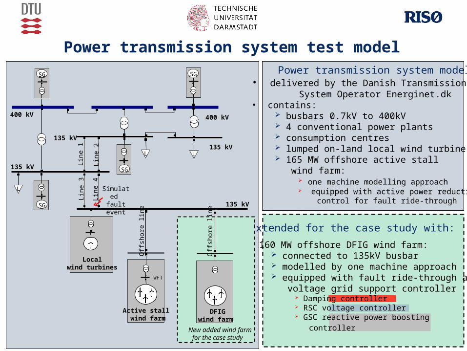
Power transmission system test model Power transmission system model:
• delivered by the Danish Transmission System Operator Energinet.dk
• contains: busbars 0.7kV to 400kV 4 conventional power plants consumption centres lumped on-land local wind turbine 165 MW offshore active stall wind farm:
one machine modelling approach equipped with active power reduction control for fault ride-through
LL
L
400 kV
Lin
e 1
Lin
e 2
Lin
e 4
Lin
e 3
Off
shor
e lin
e
Active stall wind farm
Localwind turbines
400 kV
135 kV
135 kV
135 kV
135 kV
WFT
SG SG
SG
SG
Simulated fault event
Extended for the case study with:
• 160 MW offshore DFIG wind farm: connected to 135kV busbar modelled by one machine approach equipped with fault ride-through and voltage grid support controller
Damping controller RSC voltage controller GSC reactive power boosting controller
WFT
Off
shor
e lin
e
DFIG wind farm
New added wind farmfor the case study

11
LL
L
400 kV
Lin
e 1
Lin
e 2
Lin
e 4
Lin
e 3
Off
shor
e lin
e
Active stallw ind farm
Localwind turbines
400 kV
135 kV
135 kV
135 kV
135 kV
WFT
SG SG
SG
SG
Off
shor
e lin
e
DFIGwind farm
WFT
New added wind farmfor the case study
LLLLLL
LLL
400 kV
Lin
e 1
Lin
e 2
Lin
e 4
Lin
e 3
Off
shor
e lin
e
Active stallw ind farm
Localwind turbines
400 kV
135 kV
135 kV
135 kV
135 kV
WFT
SGSG SGSGSG
SGSG
SGSG
Off
shor
e lin
e
DFIGwind farm
WFT
New added wind farmfor the case study
Case study - simulation results
2 sets of simulations:• First set of simulations:
DFIG voltage grid support capability
• Second set of simulations: illustrates DFIG voltage grid support influence on the performance of a
nearby active stall wind farm
Simulated grid fault:• 3-phase short circuit grid fault on Line 4
• Grid fault lasts for 100ms and gets cleared by
permanent isolation
• DFIG wind farm operates at its rated capacity
at the fault instant
• On-land local wind turbines are disconneted
during grid faults, as they are not
equipped with any fault ride-through control
Simulated fault event

12
5.003.752.501.250.00 [s]
190.0
150.0
110.0
70.00
30.00
-10.00
5.003.752.501.250.00 [s]
1.500
1.200
0.90
0.60
0.30
-0.000
5.003.752.501.250.00 [s]
150.0
100.0
50.00
0.00
-50.00
-100.0
DIg
SIL
EN
T
Vo
ltage
WF
T [
pu]
Act
ive
pow
er
WF
T [M
W]
Rea
ctiv
epo
wer
WF
T [M
var]
[sec]
1 2
1
1
2
2
1 - DFIG wind farm without voltage grid support - DFIG wind farm with voltage grid support2
5.003.752.501.250.00 [s]
190.0
150.0
110.0
70.00
30.00
-10.00
5.003.752.501.250.00 [s]
1.500
1.200
0.90
0.60
0.30
-0.000
5.003.752.501.250.00 [s]
150.0
100.0
50.00
0.00
-50.00
-100.0
DIg
SIL
EN
T
Vo
ltage
WF
T [
pu]
Act
ive
pow
er
WF
T [M
W]
Rea
ctiv
epo
wer
WF
T [M
var]
[sec]
1 2
1
1
2
2
1 - DFIG wind farm without voltage grid support - DFIG wind farm with voltage grid support21 - DFIG wind farm without voltage grid support - DFIG wind farm with voltage grid support2
DFIG voltage grid support capability
First set of simulations:• Focus on the DFIG wind farm performance and its interaction with the power system• It is assumed the worst case for the voltage stability:
165MW offshore active stall wind farm is not equipped with power reduction control
5.003.752.501.250.00 [s]
190.0
150.0
110.0
70.00
30.00
-10.00
5.003.752.501.250.00 [s]
1.500
1.200
0.90
0.60
0.30
-0.000
5.003.752.501.250.00 [s]
150.0
100.0
50.00
0.00
-50.00
-100.0
DIg
SIL
EN
T
Vo
ltag
e
WF
T [
pu
]A
ctiv
e po
wer
WF
T [M
W]
Rea
ctiv
e po
wer
WF
T [M
var]
[sec]
1 2
1
1
2
2
1 - DFIG wind farm without voltage grid support - DFIG wind farm with voltage grid support2

13
Second set of simulations
Focus on:How DFIG voltage grid support control influences the performance of a nearby active stall wind farm during grid faults
Four control sceneries are illustrated:
DFIG WF without voltage grid support
DFIG WF with voltage grid support
AS WF without power reduction control
AS WF with power reduction control
Scenario a Scenario b
Scenario cScenario d

14a - DFIG-WF without / AS-WF without b - DFIG-WF with /AS-WF without
10.007.505.002.500.00 [s]
300.00
200.00
100.00
0.00
-100.00
10.007.505.002.500.00 [s]
300.00
200.00
100.00
0.00
-100.00
-200.00
DIg
SIL
EN
T
Act
ive
po
we
r W
FT
[M
W]
Re
act
ive
po
we
r W
FT
[M
var]
[sec]
DFIG voltage grid support – effect on a nearby wind farm
c - DFIG-WF with /AS-WF with d - DFIG-WF without / AS-WF with
ba
c d
a b
c d

15
DFIG voltage grid support – effect on a nearby wind farm
10.007.505.002.500.00 [s]
1.100
1.070
1.040
1.010
0.98
0.95
10.007.505.002.500.00 [s]
2.00
1.50
1.00
0.50
0.00
-0.50
-1.00
DIg
SIL
EN
T
Ge
ne
rato
r sp
ee
d [
pu
]M
ech
an
ica
l po
we
r [p
u]
[sec]
a - DFIG-WF without /AS-WF without b - DFIG-WF with /AS-WF without
c - DFIG-WF with /AS-WF with d - DFIG-WF without /AS-WF with
a
b
c
a
b
cd
d

16
Remarks:
• DFIG voltage grid support control has a damping effect on the active stall wind farm, no matter whether this has or has not power reduction control (case (b) and (c))
• Worst case for the active stall wind farm (case a): DFIG wind farm has no voltage grid support control Active stall wind farm has no power reduction control
• Best case for the active stall wind farm (case b):
• DFIG wind farm is equipped with voltage grid support control
• Active stall wind farm has no power reduction control
Note that AS-WF is not subjected to torsional oscillations and there is no loss in the active power production
DFIG wind farm equipped with voltage grid support control can improve the performance
of a nearby active stall wind farm during a grid fault, without any need to implement
an additional ride-through control strategy in the active stall wind farm !!!

17
Conclusions
• DFIG controllability during grid faults is enhanced by a proper coordination design between three controllers: Damping controller - tuned to damp actively drive train torsional oscillations
excited in the drive train system during grid faults RSC voltage controller - controls grid voltage as long as RSC is not blocked by
the protection system GSC reactive power boosting controller – contributes with its maximum reactive
power capacity in case of severe grid fault
• Case study: Large DFIG wind farm - placed nearby large active stall wind farm Power transmission system generic model – delivered by Danish Transmission
System Operator Energinet.dk
• DFIG wind farm equipped with voltage grid support control participates to reestablish properly the grid voltage during grid fault can help a nearby active stall wind farm to ride-through a grid fault, without any
additional fault-ride through control setup inside the nearby active stall wind farm


