voltage grid support of dfig wind turbines during grid faults gabriele michalke university of...
TRANSCRIPT

Voltage grid support of DFIG wind turbines during grid faults
Gabriele MichalkeUniversity of Technology Darmstadt, Germany
Anca D. Hansen Risø National Laboratory, Denmark
EWEC Milan 7-10 May 2007

2
Outline
• Background
• DFIG wind turbine – modelling, control issues in case of grid faults:
• Drive train and pitch control system• DFIG system control and protection
• DFIG wind turbine – voltage grid support control
• Power transmission system test model
• Case study - simulation results
• Conclusions

3
Background
• Projects:• Ph.D project ”Variable Speed Wind Turbines - Modelling, Control and Impact on
Power Systems” funded by ”Stiftung Energieforschung Baden-Württemberg”• ”Simulation platform to model, optimise and design wind turbines” – funded by
Danish Energy Agency
• Participants:• Darmstadt Technical University• Risø National Laboratory• Aalborg Technical University
• Overall goal: • Wind farms interaction with the power system during grid faults• Advanced control design of wind farms according to the new grid codes
• Focus in this presentation: • Voltage grid support of DFIG wind turbines during grid faults

4
DFIG wind turbine – modelling, control issues in case of grid faults:
Crowbar
DFIG
~=
~ ~ ~
Power converter control
refQrefP
Control mode :• normal operation• fault operation
~=
RSC GSC
Fault detection
Drive train with gearbox
Wind turbine
Pitch angle control
DFIG system – control and protection
Aerodynamics
k
c

5
Drive train and pitch control system
ngear
J rot
Trot
J gen
Tgenc
k
• 2 mass mechanical model
eqosc J
kf
2
1
gengearrot
gengearroteq JnJ
JnJJ
2
2
Free – free frequency:
Equivalent inertia:
• Pitch control system
+
-
ref
ref
Gain schedullingKPI
+
- servoT
1
dt
d
s
1PI
Pitch angle controls the speed
Prevent over-speed both in: - normal operations - grid faults operations
Rate of change limitation important during grid faults

6
DFIG system control (normal operation)
ACDC AC
DC
RSC GSC
Power converter
PI PI PI PI dcU
GSCQ
DCrefUGSC
refQ
gridP
gridQ
gridrefP
gridrefQ
Slow control (power)
Power converter control • RSC controls Pgrid and Qgrid independently!• GSC controls UDC and QGSC=0 !
Reference signals:• Active power for RSC is defined by
MPT:
P
MPT
Maximum power tracking point
gridrefP
gridrefPPI PI PI
RSCqrefI RSC
drefI GSCqrefI GSC
drefI
RSCdIRSC
qI GSCdI
GSCqI
Fast control (current)
PI
• DC voltage is set to constant value
• GSC is reactive neutral
• Reactive power for RSC - certain
value or zero

7
DFIG system control and protection during grid faults
Power converter is very sensitive to grid faults !!!• Protection system monitors DFIG signals • Crowbar protection:
external rotor impedance
Severe grid faults triggers crowbar:• RSC disabled• DFIG behaves as SCIG• GSC can be used as a STATCOM
Damping controller
-1 -0.5 0 0.5 1 1.5 2 2.5 3-3
-2
-1
0
1
2
3
Speed [p.u.]
Ele
ctro
ma
gn
etic
to
rqu
e [
p.u
.] crowbarcrowbarcrowbar RRR 321
• Increased crowbar: improved dynamic stability of the generator reduces reactive power demand
New grid codes require:• Fault ride-through capability: wind turbine has to remain connected to the grid during grid faults
-1 -0.5 0 0.5 1 1.5 2 2.5 3-25
-20
-15
-10
-5
0
Speed [p.u.]
Re
act
ive
po
we
r [M
var]
. . . .
crowbarcrowbarcrowbar RRR 321

8
Fault Ride Through – Damping of Torsional oscillations during grid faults
10.007.505.002.500.00 [s]
1.150
1.125
1.100
1.075
1.050
1.025
10.007.505.002.500.00 [s]
3.0E+4
2.0E+4
1.0E+4
0.0E+0
-1.0E+4
DIgS
ILENT
Generator speed [pu]
Without damping controller With damping controller
Mechanical torque [Nm]
[sec]
During grid faults:• Unbalance between the torques, which act at the ends of the drive train• Drive train acts like a torsion spring
that gets untwisted• Torsional oscillations excited in the drive train
Wind speed
ref
gridrefP
-+
Damping controller
PIOptimal speed
Damping controller:• designed and tuned to damp torsional oscillations• provides active power reference for RSC control

9
DFIG wind turbine – voltage grid support control
Third stage (voltage grid support)
DFIG control structure – normal operation
GSCrefQgrid
refPgridrefQ
• During grid faults DFIG controllability is enhanced by a proper co-ordination of three controllers:
co-ordination GSC Reactive Power Boosting
GSC reactive power boostingDampingController
Damping controller
RSC Voltage Controller
RSC voltage controller
• Damping controller damps actively the torsional oscillations of the drive train system during grid faults
gridrefacU ,
gridacU
gridrefQ+
-
RSC voltage controller
PI
• RSC voltage controller controls grid voltage as long as the protection device is not triggered
• GSC reactive power boosting controls grid voltage when RSC is blocked by the protection device
10
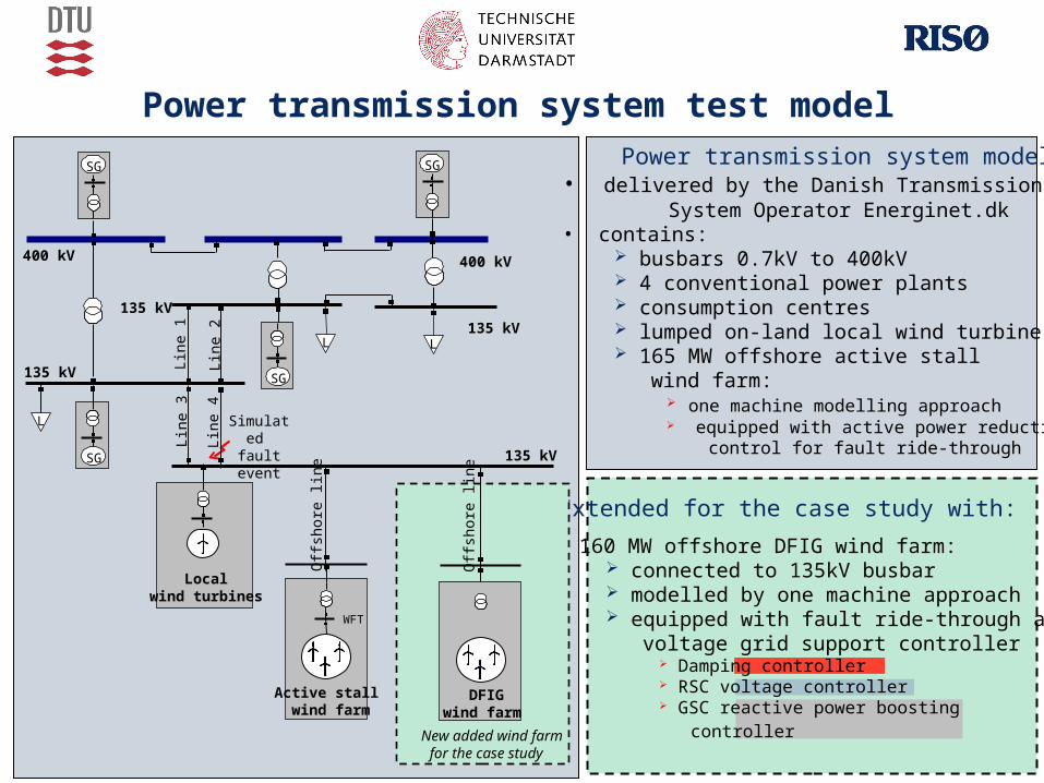
Power transmission system test model Power transmission system model:
• delivered by the Danish Transmission System Operator Energinet.dk
• contains: busbars 0.7kV to 400kV 4 conventional power plants consumption centres lumped on-land local wind turbine 165 MW offshore active stall wind farm:
one machine modelling approach equipped with active power reduction control for fault ride-through
LL
L
400 kV
Lin
e 1
Lin
e 2
Lin
e 4
Lin
e 3
Off
shor
e lin
e
Active stall wind farm
Localwind turbines
400 kV
135 kV
135 kV
135 kV
135 kV
WFT
SG SG
SG
SG
Simulated fault event
Extended for the case study with:
• 160 MW offshore DFIG wind farm: connected to 135kV busbar modelled by one machine approach equipped with fault ride-through and voltage grid support controller
Damping controller RSC voltage controller GSC reactive power boosting controller
WFT
Off
shor
e lin
e
DFIG wind farm
New added wind farmfor the case study

11
LL
L
400 kV
Lin
e 1
Lin
e 2
Lin
e 4
Lin
e 3
Off
shor
e lin
e
Active stallw ind farm
Localwind turbines
400 kV
135 kV
135 kV
135 kV
135 kV
WFT
SG SG
SG
SG
Off
shor
e lin
e
DFIGwind farm
WFT
New added wind farmfor the case study
LLLLLL
LLL
400 kV
Lin
e 1
Lin
e 2
Lin
e 4
Lin
e 3
Off
shor
e lin
e
Active stallw ind farm
Localwind turbines
400 kV
135 kV
135 kV
135 kV
135 kV
WFT
SGSG SGSGSG
SGSG
SGSG
Off
shor
e lin
e
DFIGwind farm
WFT
New added wind farmfor the case study
Case study - simulation results
2 sets of simulations:• First set of simulations:
DFIG voltage grid support capability
• Second set of simulations: illustrates DFIG voltage grid support influence on the performance of a
nearby active stall wind farm
Simulated grid fault:• 3-phase short circuit grid fault on Line 4
• Grid fault lasts for 100ms and gets cleared by
permanent isolation
• DFIG wind farm operates at its rated capacity
at the fault instant
• On-land local wind turbines are disconneted
during grid faults, as they are not
equipped with any fault ride-through control
Simulated fault event

12
5.003.752.501.250.00 [s]
190.0
150.0
110.0
70.00
30.00
-10.00
5.003.752.501.250.00 [s]
1.500
1.200
0.90
0.60
0.30
-0.000
5.003.752.501.250.00 [s]
150.0
100.0
50.00
0.00
-50.00
-100.0
DIg
SIL
EN
T
Vo
ltage
WF
T [
pu]
Act
ive
pow
er
WF
T [M
W]
Rea
ctiv
epo
wer
WF
T [M
var]
[sec]
1 2
1
1
2
2
1 - DFIG wind farm without voltage grid support - DFIG wind farm with voltage grid support2
5.003.752.501.250.00 [s]
190.0
150.0
110.0
70.00
30.00
-10.00
5.003.752.501.250.00 [s]
1.500
1.200
0.90
0.60
0.30
-0.000
5.003.752.501.250.00 [s]
150.0
100.0
50.00
0.00
-50.00
-100.0
DIg
SIL
EN
T
Vo
ltage
WF
T [
pu]
Act
ive
pow
er
WF
T [M
W]
Rea
ctiv
epo
wer
WF
T [M
var]
[sec]
1 2
1
1
2
2
1 - DFIG wind farm without voltage grid support - DFIG wind farm with voltage grid support21 - DFIG wind farm without voltage grid support - DFIG wind farm with voltage grid support2
DFIG voltage grid support capability
First set of simulations:• Focus on the DFIG wind farm performance and its interaction with the power system• It is assumed the worst case for the voltage stability:
165MW offshore active stall wind farm is not equipped with power reduction control
5.003.752.501.250.00 [s]
190.0
150.0
110.0
70.00
30.00
-10.00
5.003.752.501.250.00 [s]
1.500
1.200
0.90
0.60
0.30
-0.000
5.003.752.501.250.00 [s]
150.0
100.0
50.00
0.00
-50.00
-100.0
DIg
SIL
EN
T
Vo
ltag
e
WF
T [
pu
]A
ctiv
e po
wer
WF
T [M
W]
Rea
ctiv
e po
wer
WF
T [M
var]
[sec]
1 2
1
1
2
2
1 - DFIG wind farm without voltage grid support - DFIG wind farm with voltage grid support2

13
Second set of simulations
Focus on:How DFIG voltage grid support control influences the performance of a nearby active stall wind farm during grid faults
Four control sceneries are illustrated:
DFIG WF without voltage grid support
DFIG WF with voltage grid support
AS WF without power reduction control
AS WF with power reduction control
Scenario a Scenario b
Scenario cScenario d

14a - DFIG-WF without / AS-WF without b - DFIG-WF with /AS-WF without
10.007.505.002.500.00 [s]
300.00
200.00
100.00
0.00
-100.00
10.007.505.002.500.00 [s]
300.00
200.00
100.00
0.00
-100.00
-200.00
DIg
SIL
EN
T
Act
ive
po
we
r W
FT
[M
W]
Re
act
ive
po
we
r W
FT
[M
var]
[sec]
DFIG voltage grid support – effect on a nearby wind farm
c - DFIG-WF with /AS-WF with d - DFIG-WF without / AS-WF with
ba
c d
a b
c d

15
DFIG voltage grid support – effect on a nearby wind farm
10.007.505.002.500.00 [s]
1.100
1.070
1.040
1.010
0.98
0.95
10.007.505.002.500.00 [s]
2.00
1.50
1.00
0.50
0.00
-0.50
-1.00
DIg
SIL
EN
T
Ge
ne
rato
r sp
ee
d [
pu
]M
ech
an
ica
l po
we
r [p
u]
[sec]
a - DFIG-WF without /AS-WF without b - DFIG-WF with /AS-WF without
c - DFIG-WF with /AS-WF with d - DFIG-WF without /AS-WF with
a
b
c
a
b
cd
d

16
Remarks:
• DFIG voltage grid support control has a damping effect on the active stall wind farm, no matter whether this has or has not power reduction control (case (b) and (c))
• Worst case for the active stall wind farm (case a): DFIG wind farm has no voltage grid support control Active stall wind farm has no power reduction control
• Best case for the active stall wind farm (case b):
• DFIG wind farm is equipped with voltage grid support control
• Active stall wind farm has no power reduction control
Note that AS-WF is not subjected to torsional oscillations and there is no loss in the active power production
DFIG wind farm equipped with voltage grid support control can improve the performance
of a nearby active stall wind farm during a grid fault, without any need to implement
an additional ride-through control strategy in the active stall wind farm !!!

17
Conclusions
• DFIG controllability during grid faults is enhanced by a proper coordination design between three controllers: Damping controller - tuned to damp actively drive train torsional oscillations
excited in the drive train system during grid faults RSC voltage controller - controls grid voltage as long as RSC is not blocked by
the protection system GSC reactive power boosting controller – contributes with its maximum reactive
power capacity in case of severe grid fault
• Case study: Large DFIG wind farm - placed nearby large active stall wind farm Power transmission system generic model – delivered by Danish Transmission
System Operator Energinet.dk
• DFIG wind farm equipped with voltage grid support control participates to reestablish properly the grid voltage during grid fault can help a nearby active stall wind farm to ride-through a grid fault, without any
additional fault-ride through control setup inside the nearby active stall wind farm