
W EEx nA non-sparkingmotors
R o t a t i n g E l e c t r i c a l M a c h i n e s
Frames 80 - 355L
2204E

W EEx nA non-sparking motors80 - 355L
2204E Issue 1.2e W EEx nA non-sparking motors
Brook CromptonBrook Crompton is a leading manufacturer of
electric motors for the global industrial
market, with motor solutions which benefit a
wide range of customers.
Our products are used in almost every
industrial activity including water treatment,
building services, chemical/petrochemicals,
general processing and manufacturing where
they drive fans, pumps, compressors and
conveyors, amongst other things.
Brook Crompton incorporates many well
known names including Brook Motors,
Crompton Parkinson, Electrodrives,
Newman, Bull Electric and Hawker Siddeley
Electric Motors.
We have extensive stocks of motors around
the world, backed-up by a network of
distributors, ensuring excellent local support
wherever needed.
Quality assuranceStringent quality procedures are observed
from first design to finished product in
accordance with the ISO9001 documented
quality systems.
All of our factories have been assessed to
meet these requirements, a further
assurance that only the highest possible
standards of quality are accepted.
W EEx nA motorsBrook Crompton has one of the widest
available ranges of electric motors for
operation in hazardous atmospheres and
hostile environments.
We have over 90 years’ technical and design
experience in this most specialised market
and are able to ensure the correct selection
of motors for any application, taking into full
account the two most important factors to be
considered - safety and economy.
The W EEx nA non-sparking motor range
covers products with outputs from as little as
0.18kW to 400kW in frame sizes 80 to 355L.
Motors are manufactured in factories that are
licensed by a European notified body (eg
EECS/BASEEFA, PTB), meeting rigorous
quality controls.
Benefits include:• high efficiency for low running costs
• high reliability for long life
• low noise levels
• cool running for long insulation life
• Eurovoltage: 400V ±10%
• dual frequency: 50Hz and 60Hz
• high power factors
• high torque with smooth acceleration and
low current
• 2-year warranty
• IP55 protection
• 4-position cable entry
EfficiencyBrook Crompton are an approved
manufacturer of ac electric motors within the
UK Government’s Enhanced Capital
Allowance (ECA) scheme. A wide range of
single and multi-speed motors are included
on the UK Energy Technology List. Please
check the ECA scheme website:
www.eca.gov.uk at time of purchase for
current listing.
ATEXBrook Crompton’s range of EEx nA motors
are fully compliant with the requirements of
ATEX Directive (94/9/EC).
2

Standards and environment
3
2204E Issue 1.2e W EEx nA non-sparking motors
Standards
EnvironmentEnclosureAll motors have degrees of IP protection
as defined in IEC EN 60034-5.
European directivesFour European directives apply in
varying degrees to ac induction motors.
Brook Crompton comply in the following
manner:
Motor coolingMotors are cooled in accordance with
EN 60034-6. The normal arrangement
is IC411 (Totally Enclosed Fan Ventilated) via
a fan mounted at the non-drive end.
Alternative methods of cooling available on
request.
Reference numbers
Motor CE marked
Standards
Documentation for customers’ technical file
Safety instructions with every motor
Comment
Compliance with European directives applying to AC induction motors
73/23/EEC
93/68/EEC
Yes
EN 60034
Declaration of conformity
Yes
Relevant electrical
equipment operating
between
50 to 1000 volts AC
Directives Low voltage(LV)
89/392/EEC
91/368/EEC
93/44/EEC
93/68/EEC
No
Not applicable
Certificate of incorporation
Yes
Statement(2)
Machinery(MD)
89/336/EEC
92/31/EEC
93/68/EEC
No
EN 60034-1
Statement(1)
Yes
Component
Electromagnetic compatibility(EMC)
(1) Motors operating from a correctly applied, sinusoidal (AC) supply meet the requirements of the EMC directive and are within the limits specified in standard
EN 60034-1(2) When installed in accordance with our customer safety and installation and maintenance instructions, they can be put into service only when the machinery into
which they are being incorporated, has been declared to be in conformity with the machinery directive in accordance with Article 4(2) and Annex IIB of that Directive
(98/37/EEC)
94/9/EC
YES
EN 50014
EN 50021
Declaration of conformity
Yes
Hazardous atmosphere
equipment - mandatory
after July 2003
ATEX
standard motor complies optional
Range UK European
National standard
International North American
Standard
Outputs
Performance
Dimensions
Mounting
Degrees of IP protection
EEx nA
Non-sparking
BS
BS 5000 part 10,
appendix A
BS 4999 Part 101
BS 4999 part 141
EN 60034-7
EN 60034-5
EN 50014
EN 50021
EN 50014
EN 50021
BS
BS 5000 part 10
BS 4999 part 101
as DIN and NF
EN 60034-7
EN 60034-5
VDE
–
VDE 0530 part 1
–
–
–
DIN
DIN 42673, DIN 42677
–
DIN 42673, DIN 42677
DIN 42950
DIN 40050
-
NF
NF C51-110
NF C51-111
NF C51-105, NF C51-120
NF C51-117
NF C51-115
–
IEC
–
IEC 60034-1
IEC 60072-1
IEC 60034-7
IEC 60034-5
IEC 60079-15
NEMA*
MG1 part 10
MG1 part 12
MG1 part 4
MG1 part 4
MG1-1.26B
–
Standards
-
Motors complying with IEC 60034-1 also comply with many of the national standards of other European countries, eg CEI 203 (Italy), NBN7 (Belgium), NEN 3173 (Netherlands),SEN 2601 01 (Sweden) *Motors to NEMA standards have CSA approval and generally comply with Canadian (EEMAC) standards.

EEx nA (non-sparking) motorsFrame Sizes W-DF80 to W-DF355
Suitable for use in Group II Zone 2 locations.
GeneralThe construction of EEx nA motors is similar
to standard TEFV motors, but with special
attention to eliminate production of arcs,
sparks or dangerous surface temperatures.
Air gap concentricity is rigidly inspected
throughout manufacture, and the structure of
the motor is impact-tested. All motors comply
with the requirements of the ATEX Directive
(94/9/EC).
Temperature classAn important feature of the motor design is
the limitation imposed on the external or
internal surface temperature that can be
attained under all conditions except starting.
This range of motors is suitable for use in
gases with auto ignition temperature not
lower than T3, ie 200°C. For temperature
classes T4, T5 and T6 - please consult Brook
Crompton.
Terminal boxStandard and alternative terminal box
positions are available as detailed in the table
below (positions detailed are looking on drive
end of motor).
Impact coversDesigned to prevent the ingress of falling
foreign bodies, impact covers are fitted on
motors when mounted verticaly, shaft down.
CertificationThe motors are certified by a European
notified body who also grant the licence to
manufacture
Dual zonesSome installations may be subjected to more
than one type of hazard. The presence of
gases and vapours etc may occur with
combustible dusts. Under these
circumstances, it is possible to supply motors
with certification for both hazards. Further
details are available from Brook Crompton.
EEx nA EEMUA (non-sparking)motorsFrame sizes W-DF80 to W-DF355
Suitable for use in Group II Zone 2 locations.
GeneralThe Brook Crompton EEx nA EEMUA motor
range covers products from 0.18kW to
280kW.
StandardsAll motors comply with the requirements of
EEMUA (The Engineering Equipment and
Materials Users Association) Pub no 132-1988
and with leading petro-chemical industry
specifications. They are manufactured in
accordance with EN 50021 and are certified
for use in Zone 2, hazardous areas.
PerformanceIn accordance with BS 5000 Part 99 and
IEC60034-1. Motors up to and including 40kW
rated output have a starting characteristic in
accordance with BS 4999 Part 112, design N.
Motors above 40kW rated output have a
characteristic in accordance with design D.
Full performance data is available on request.
Temperature classMaximum surface temperatures are limited to
T3.
Mechanical featuresFerrous cooling fans
Sheet steel fan covers
Collar type eyebolts
Cast iron stator frames and endshields
Reduced balance
IP55 enclosure
Specially stamped nameplate
Through greasing frames 160 and above
Phase barriers, for use with either shell
clamps or uninsulated cable lugs, are
standard on motors to EEMUA. By fitting a
larger terminal box, solid aluminium cables
can be catered for.
EEx nA and EEx nA EEMUA specification
2204E Issue 1.2e W EEx nA non-sparking motors
Certificate Numbers
W-DF80 to W-DF180
W-DF200 to W-DF355L
Frame size
BAS00ATEX3119X
BAS00ATEX3133X
Certificate No
Terminal box positions available
W-DF80-90
W-DF100-180
W-DF200-355
Frame size
-
Alternative
Standard
Standard
Standard
Alternative
Alternative
Alternative
Alternative
EEx nA heater ratings
80
90
100
112
132
160
180
200
225
250
280
315
355
Frame size
12
12
12
14
24
40
40
29
48
48
96
96
192
12
12
12
14
24
40
40
29
42
42
84
84
169
240V 110V
Heater rating
Terminal pin cable capacity and terminal nut tightening torque
80-100
112-132
160-180
200L-280S
280M-355L
Frame size
80-100
112-132
112-132
160-180
160-180
200-280S
280M-355L
4 (M4)
10 (M5)
10 (M5)
16 (M6)
16 (M6)
95 (M10)
300 (M10)
T box size Mains terminals
4
4
4
4
4
2.5
2.5
Aux terminals
1.5
3
3
5
5
26
26
Mains terminals
0.5-0.8
0.5-0.8
0.5-0.8
0.5-0.8
0.5-0.8
1
1
Aux terminals
Cable capacity (mm2) Tightening torque (Nm)
EEx nA motor certification plate
N
Top RHSLHS
�
4
Vertically mounted motors fitted with impact cover
W-DF80M-90L
W-DF100L-112M
W-DF132S-180L
W-UDF200LX
W-UDF225S/M
W-UDF250ME
W-UDF280SE
W-UDF280ME
W-UDF315SE
W-UDF315ME
W-UDF315M/L
W-UDF355S/M/L
European frame
W-DF80M-90L
W-DF100L-112M
W-DF132S-180L
W-DF200LX
W-DF225S/M
W-DF250S
W-DF250M
W-DF280S
W-DF280M
W-DF315S
W-DF315M/L
W-DF355S/M/L
29
30
40
45
45
45
48
48
48
48
53
65
BS frame
Increase
in L Dim

2204E Issue 1.2e W EEx nA non-sparking motors
Mounting options
Approximate shipping specifications
W-DF80M
W-DF90S
W-DF90L
W-DF100L
W-DF112M
W-DF132S
W-DF132M
W-DF160M
W-DF160L
W-DF180M
W-DF180L
W-UDF200LX
W-UDF225S
W-UDF225M
W-UDF250ME
W-UDF280SE
W-UDF280ME
W-UDF315SE
W-UDF315ME
W-UDF315M
W-UDF315L
W-UDF355S
W-UDF355M
W-UDF355L
W-DF80M
W-DF90S
W-DF90L
W-DF100L
W-DF112M
W-DF132S
W-DF132M
W-DF160M
W-DF160L
W-DF180M
W-DF180L
W-DF200LX
W-DF225S
W-DF225M
W-DF250S
W-DF250M
W-DF280S
W-DF280M
W-DF315S
W-DF315M
W-DF315L
W-DF355S
W-DF355M
W-DF355L
BS
15
19
22
35.5
45
68
72.5
121
133
162
177.5
255
320
375
420
570
660
800
1000
1100
1300
2000
2300
2500
Net weight (kg) Gross weight (kg) Cubage (m3)
16.5
20.5
23.5
38
48
71
78.5
133
145
178
193.5
270
335
390
460
610
721
871
1095
1195
1395
2120
2420
2620
0.02
0.03
0.03
0.03
0.05
0.08
0.08
0.15
0.15
0.21
0.21
0.30
0.37
0.37
0.63
0.70
1.2
1.2
1.8
1.8
1.8
2.3
2.3
2.3
European
Type
5

2204E Issue 1.2e W EEx nA non-sparking motors
kW(hp)
Jkgm2
PN
nmin–1
Type
0.75(1)
1.1(1.5)
1.5(2)
2.2(3)
3(4)
4(5.5)
5.5(7.5
7.5(10)
11(15)
15(20)
18.5(25
22(30)
30(40)
37(50)
45(60)
55(75)
2850
2875
2850
2860
2880
2870
2910
2900
2935
2935
2940
2950
2940
2940
2955
2955
W-DF80ME(1)
W-DF80MJ(1)
W-DF90SF(1)
W-DF90LM(1)
W-DF100LJ(1)
W-DF112MM(1)
W-DF132SE(1)
W-DF132SJ(1)
W-DF160MB(1)
W-DF160MJ(1)
W-DF160LR(1)
W-DF180ME(1)
W-UDF200LGX(2)
W-DF200LGX(3)
W-UDF200LNX(2)
W-DF200LNX(3)
W-UDF225MN(2)
W-DF225MN(3)
W-UDF250MNE(2)
W-DF250SN(3)
0.0014
0.0019
0.0023
0.0028
0.006
0.008
0.017
0.02
0.039
0.045
0.056
0.094
0.15
0.18
0.47
0.56
LPA
dB(A)
64
64
64
64
60
60
66
66
68
68
68
68
73
73
75
75
380 VA
400 VA
415 VA
ηη1.0 PN
0.75 PN
0.5 PN
MN
NmMA
MN
IAIN
IN
1.77
2.51
3.4
4.6
5.9
7.6
10.5
14.0
20.7
27.7
34
39
55
67
81
99
1.69
2.39
3.2
4.4
5.7
7.2
10.0
13.3
19.7
26.3
32
37
52
64
77
94
1.69
2.39
3.2
4.4
5.7
7.2
10.0
13.3
19.7
26.3
32
37
51
62
74
90
77.077.073.081.081.078.082.083.081.084.085.083.086.587.086.588.089.089.089.589.588.089.590.089.090.590.889.791.391.591.291.892.191.392.292.291.092.993.092.093.393.492.593.793.792.594.094.293.0
Cos Ø1.0 PN
0.75 PN
0.5 PN
0.830.77 0.650.820.750.630.820.750.630.860.810.710.880.830.750.910.890.850.890.850.730.910.890.820.890.860.790.900.880.800.910.890.810.920.900.840.890.860.800.890.860.800.900.880.830.900.880.83
2.5
3.7
5.0
7.4
10.0
13.3
18.1
24.7
35.8
48.8
60.2
71.4
97
120
145
178
2.2
2.7
2.5
2.5
3.0
3.0
2.7
2.5
2.2
2.2
2.4
2.2
2.7
2.7
2.3
2.3
MS
MN
MK
MN
2.0
2.4
2.2
2.2
2.6
2.8
2.4
2.3
1.8
1.9
1.9
1.9
2.3
2.3
1.9
1.9
2.5
2.7
3.0
3.0
3.1
3.1
3.1
3.0
3.0
3.1
3.2
3.1
2.9
2.9
2.8
2.8
MA
MN
Y
–
–
–
–
–
0.85
0.80
0.75
0.65
0.65
0.78
0.65
0.75
0.75
0.65
0.65
IAINY
–
–
–
–
–
2.8
2.4
2.5
2.5
2.6
2.7
2.8
2.5
2.5
2.5
2.5
MS
MN
Y
–
–
–
–
–
0.80
0.75
0.70
0.60
0.60
0.65
0.60
0.60
0.60
0.50
0.50
5.5
6.7
6.0
6.3
7.8
7.8
8.2
8.2
7.8
8.0
8.7
9.0
7.8
7.8
7.8
7.8
Mea
n so
und
pres
sure
leve
l
@ 1
m o
n no
load
Roto
r ine
rtia
WK
2
Star
del
tapu
ll up
torq
ue
Dire
ct o
n lin
e
pull
out t
orqu
e ra
tio
Dire
ct o
n lin
e
star
ting
curr
ent r
atio
Dire
ct o
n lin
e
star
ting
torq
ue ra
tio
Full
load
torq
ue
Pow
er fa
ctor
Effic
ienc
y
Full
load
cur
rent
at
rate
d vo
ltage
Fram
e re
fere
nce
and
size
Full
load
spe
ed in
revo
lutio
ns p
er m
inut
e
Rate
d po
wer
Dire
ct o
n lin
e
pull
up to
rque
Star
del
tast
artin
g cu
rren
t rat
io
Star
del
tast
artin
g to
rque
ratio
(1)
Performance data3000 min–1 (2 pole)
(1) European and BS frame reference(2) European frame reference(3) BS frame reference
For performance curves and notes - see page 236
{ }{ }{ }{ }{ }{ }{ }{ }{ }{ }{ }{ }{ }{ }{ }{ }

2204E Issue 1.2e W EEx nA non-sparking motors
Performance data3000 min–1 (2 pole)
kW(hp)
Jkgm2
PN
Mea
n so
und
pres
sure
leve
l
@ 1
m o
n no
load
Roto
r ine
rtia
WK
2
Star
del
tapu
ll up
torq
ue
Dire
ct o
n lin
e
pull
out t
orqu
e ra
tio
Dire
ct o
n lin
e
star
ting
curr
ent r
atio
Dire
ct o
n lin
e
star
ting
torq
ue ra
tio
Full
load
torq
ue
Pow
er fa
ctor
Effic
ienc
y
Full
load
cur
rent
at
rate
d vo
ltage
Fram
e re
fere
nce
and
size
Full
load
spe
ed in
revo
lutio
ns p
er m
inut
e
Rate
d po
wer
Dire
ct o
n lin
e
pull
up to
rque
Star
del
tast
artin
g cu
rren
t rat
io
Star
del
tast
artin
g to
rque
ratio
(1)
nmin–1
Type
.75(100)
90(125)
110(150)
132(175)
150(200)
160(215)
185(250)
200(270)
225(300)
250(335)
280(375)
315(420)
355(475)
400(535)
2960
2960
2978
2978
2980
2980
2980
2978
2982
2982
2982
2982
2982
2985
0.7
0.8
1.4
1.7
2.4
2.6
2.8
2.8
5.0
5.3
5.9
6.3
7.0
8.0
LPA
dB(A)
77
77
78
78
80
80
80
80
80
80
80
80
80
80
380 VA
400 VA
415 VA
ηη1.0 PN
0.75 PN
0.5 PN
MN
NmMA
MN
IAIN
IN
134
160
194
233
260
277
320
346
398
445
496
551
621
691
127
152
184
221
247
264
304
329
379
421
471
524
590
657
123
146
177
213
238
254
294
317
364
405
454
505
569
633
94.694.993.495.095.093.595.895.494.095.895.494.096.295.894.396.395.994.496.496.294.896.496.294.896.495.994.696.496.094.896.496.194.996.596.295.296.596.395.496.696.495.6
Cos Ø1.0 PN
0.75 PN
0.5 PN
0.900.880.830.900.880.830.900.880.830.900.880.830.910.890.850.910.890.850.910.890.850.910.890.850.890.870.850.890.870.850.890.870.850.900.890.860.900.890.860.910.900.87
242
290
353
423
481
513
593
641
721
801
897
1009
1137
1280
2.2
2.2
2.2
2.2
2.0
2.0
2.0
1.85
2.0
2.0
2.0
2.0
2.0
2.0
MS
MN
MK
MN
2.0
2.0
1.8
1.8
1.7
1.7
1.7
1.6
1.6
1.6
1.6
1.6
1.6
1.6
3.0
3.0
2.9
2.9
2.75
2.75
2.75
2.5
2.7
2.7
2.7
2.7
2.7
2.7
MA
MN
Y
0.65
0.65
0.65
0.65
0.60
0.60
0.60
0.55
0.65
0.65
0.65
0.65
0.65
0.65
IAINY
2.5
2.5
2.5
2.5
2.5
2.5
2.5
2.3
2.3
2.3
2.3
2.3
2.3
2.3
MS
MN
Y
0.50
0.50
0.45
0.45
0.45
0.45
0.45
0.42
0.45
0.45
0.45
0.45
0.45
0.45
7.8
7.8
7.8
7.8
7.8
7.8
7.8
7.2
7.5
7.5
7.5
7.5
7.5
7.5
W-UDF280SNE(2)
W-DF250MN(3)
W-UDF280MNE(2)
W-DF280SN(3)
W-UDF315SNE(2)
W-DF280MN(3)
W-UDF315MNE(2)
W-DF315SN(3)
W-UDF315MN(2)
W-DF315MN(3)
W-UDF315MP(2)
W-DF315MP(3)
W-UDF315LN(2)
W-DF315LN(3)
W-UDF315LN(2)
W-DF315LN(3)
W-UDF355SG(2)
W-DF355SG(3)
W-UDF355SJ(2)
W-DF355SJ(3)
W-UDF355SN(1)
W-DF315SN(3)
W-UDF355MJ(2)
W-DF355MJ(3)
W-UDF355MN(2)
W-DF355MN(3)
W-UDF355LN(2)
W-DF355LN(3)
(1) European and BS frame reference(2) European frame reference(3) BS frame reference
For performance curves and notes - see page 23 7
{ }{ }{ }{ }{ }{ }{ }{ }{ }{ }{ }{ }{ }{ }

2204E Issue 1.2e W EEx nA non-sparking motors
kW(hp)
Jkgm2
PN
nmin–1
Type
0.55(0.75)
0.75(1)
1.1(1.5)
1.5(2)
2.2(3)
3(4)
4(5.5)
5.5(7.5)
7.5(10)
11(15)
15(20)
18.5(25)
22(30)
30(40)
37(50)
45(60)
55(75)
1410
1410
1435
1435
1440
1445
1445
1450
1460
1470
1470
1470
1470
1470
1470
1475
1475
0.0015
0.0019
0.0028
0.0035
0.008
0.09
0.015
0.027
0.029
0.068
0.084
0.16
0.19
0.31
0.45
0.65
0.75
LPA
dB(A)
47
47
48
48
54
54
56
59
59
63
63
62
62
65
66
67
67
380 VA
400 VA
415 VA
ηη1.0 PN
0.75 PN
0.5 PN
MN
NmMA
MN
IAIN
IN
1.66
1.97
2.76
3.7
5.0
6.7
8.7
11.6
15.4
22
29.5
36
43
57
70
84
103
1.58
1.88
2.63
3.5
4.8
6.4
8.3
11.0
14.7
21
28.1
34
41
54
66
80
98
1.58
1.88
2.63
3.5
4.8
6.4
8.3
11.0
14.7
21
28.1
34
41
52
64
77
94
75.075.070.078.079.077.079.580.078.081.082.080.083.583.583.084.585.585.086.587.086.088.088.588.089.089.589.091.091.290.591.892.391.792.292.391.392.692.992.593.293.292.393.693.692.593.994.293.094.294.693.5
Cos Ø1.0 PN
0.75 PN
0.5 PN
0.670.570.450.740.650.500.760.660.520.770.680.550.800.740.610.800.740.610.800.740.600.820.760.640.830.770.650.830.790.670.840.790.680.840.790.640.840.800.690.860.840.750.860.840.750.860.840.750.860.840.75
3.7
5.1
7.5
10.1
14.8
20.2
26.5
36.2
49.4
71.5
97.5
120
143
195
240
292
357
2.0
1.8
2.2
2.5
2.2
2.3
2.5
2.4
2.5
2.5
2.5
2.8
2.5
2.3
2.3
2.7
2.7
MS
MN
MK
MN
1.8
1.6
2.0
2.2
1.9
2.1
2.1
2.1
2.1
2.0
2.0
2.2
2.0
1.9
1.9
1.9
1.9
2.4
2.2
2.5
2.8
2.5
2.5
2.9
2.9
2.9
2.9
2.9
3.2
2.9
3.2
3.2
3.2
3.2
MA
MN
Y
–
–
–
–
–
–
0.75
0.70
0.70
0.65
0.65
0.80
0.75
0.7
0.7
0.75
0.75
IAINY
–
–
–
–
–
–
2.2
2.2
2.2
2.3
2.3
2.6
2.2
2.4
2.3
2.5
2.5
MS
MN
Y
–
–
–
–
–
–
0.65
0.60
0.60
0.50
0.50
0.65
0.60
0.55
0.55
0.55
0.55
4.2
4.4
5.1
5.6
5.5
5.8
7.0
7.5
7.5
7.7
7.7
8.4
7.5
7.5
7.3
7.7
7.7
Performance data1500 min–1 (4 pole)
Mea
n so
und
pres
sure
leve
l
@ 1
m o
n no
load
Roto
r ine
rtia
WK
2
Star
del
tapu
ll up
torq
ue
Dire
ct o
n lin
e
pull
out t
orqu
e ra
tio
Dire
ct o
n lin
e
star
ting
curr
ent r
atio
Dire
ct o
n lin
e
star
ting
torq
ue ra
tio
Full
load
torq
ue
Pow
er fa
ctor
Effic
ienc
y
Full
load
cur
rent
at
rate
d vo
ltage
Fram
e re
fere
nce
and
size
Full
load
spe
ed in
revo
lutio
ns p
er m
inut
e
Rate
d po
wer
Dire
ct o
n lin
e
pull
up to
rque
Star
del
tast
artin
g cu
rren
t rat
io
Star
del
tast
artin
g to
rque
ratio
(1)
W-DF80ME(1)
W-DF80MG(1)
W-DF90SE(1)
W-DF90LK(1)
W-DF100LJ(1)
W-DF100LR(1)
W-DF112MS(1)
W-DF132SJ(1)
W-DF132MR(1)
W-DF160MJ(1)
W-DF160LR(1)
W-DF180ME(1)
W-DF180LJ(1)
W-UDF200LNX(2)
W-DF200LNX(3)
W-UDF225SN(2)
W-DF225SN(3)
W-UDF225MN(2)
W-DF225MN(3)
W-UDF250MNE(2)
W-DF250SN(3)
(1) European and BS frame reference(2) European frame reference(3) BS frame reference
For performance curves and notes - see page 238
{ }{ }{ }{ }{ }{ }{ }{ }{ }{ }{ }{ }{ }{ }{ }{ }{ }

2204E Issue 1.2e W EEx nA non-sparking motors
kW(hp)
Jkgm2
PN
nmin–1
Type
.75(100)
90(125)
110(150)
132(175)
150(200)
160(215)
185(250)
200(270)
225(300)
250(335)
280(375)
315(420)
355(475)
400(535)
1475
1475
1480
1482
1485
1487
1487
1485
1487
1487
1487
1487
1487
1487
W-UDF280SNE(2)
W-DF250MN(3)
W-UDF280MNE(2)
W-DF280SN(3)
W-UDF315SNE(2)
W-DF280MN(3)
W-UDF315MNE(2)
W-DF315SN(3)
W-UDF315MN(2)
W-DF315MN(3)
W-UDF315MP(2)
W-DF315MP(3)
W-UDF315LN(2)
W-DF315LN(3)
W-UDF315LN(2)
W-DF315LN(3)
W-UDF355SG(2)
W-DF355SG(3)
W-UDF355SJ(2)
W-DF355SJ(3)
W-UDF355SN(2)
W-DF355SN(3)
W-UDF355MJ(2)
W-DF355MJ(3)
W-UDF355MN(2)
W-DF355MN(3)
W-UDF355LN(2)
W-DF355LN(3)
1.4
1.6
3.2
3.7
4.4
4.7
5.5
5.5
8.2
9.5
10.6
11.9
13.2
14.6
LPA
dB(A)
69
69
71
71
73
73
73
73
76
76
76
79
79
79
380 VA
400 VA
415 VA
ηη1.0 PN
0.75 PN
0.5 PN
MN
NmMA
MN
IAIN
IN
131
157
191
229
257
274
316
342
379
420
470
528
588
662
126
151
184
220
247
264
305
329
365
405
453
509
567
638
94.794.893.595.095.193.895.695.594.095.895.694.295.995.794.795.995.794.796.095.895.096.095.895.096.496.295.496.696.495.696.796.595.896.896.796.096.896.796.396.996.896.5
Cos Ø1.0 PN
0.75 PN
0.5 PN
0.870.85 0.750.870.850.750.870.850.770.870.850.770.880.860.780.880.860.780.880.860.780.880.860.780.890.860.800.890.860.800.890.870.810.890.880.830.900.890.840.900.890.84
486
583
710
852
965
1029
1190
1286
1445
1605
1798
2023
2280
2569
2.4
2.5
2.4
2.4
2.4
2.4
2.4
2.3
2.1
2.1
2.1
2.1
2.1
2.1
MS
MN
MK
MN
1.9
2.0
2.0
2.0
2.0
2.0
2.0
1.9
1.7
1.7
1.7
1.7
1.7
1.7
2.7
2.8
2.6
2.6
2.7
2.7
2.7
2.6
2.5
2.5
2.5
2.5
2.5
2.5
MA
MN
Y
0.72
0.75
0.70
0.70
0.70
0.70
0.70
0.65
0.65
0.65
0.65
0.65
0.65
0.65
IAINY
2.3
2.4
2.5
2.5
2.5
2.5
2.5
2.4
2.2
2.2
2.2
2.2
2.2
2.2
MS
MN
Y
0.54
0.55
0.5
0.5
0.5
0.5
0.5
0.45
0.5
0.5
0.5
0.5
0.5
0.5
7.4
7.4
7.7
7.7
7.8
7.8
7.8
7.6
7.2
7.2
7.2
7.2
7.2
7.2
Performance data1500 min–1 (4 pole)
Mea
n so
und
pres
sure
leve
l
@ 1
m o
n no
load
Roto
r ine
rtia
WK
2
Star
del
tapu
ll up
torq
ue
Dire
ct o
n lin
e
pull
out t
orqu
e ra
tio
Dire
ct o
n lin
e
star
ting
curr
ent r
atio
Dire
ct o
n lin
e
star
ting
torq
ue ra
tio
Full
load
torq
ue
Pow
er fa
ctor
Effic
ienc
y
Full
load
cur
rent
at
rate
d vo
ltage
Fram
e re
fere
nce
and
size
Full
load
spe
ed in
revo
lutio
ns p
er m
inut
e
Rate
d po
wer
Dire
ct o
n lin
e
pull
up to
rque
Star
del
tast
artin
g cu
rren
t rat
io
Star
del
tast
artin
g to
rque
ratio
(1)
138
165
201
241
270
288
333
360
398
442
494
556
619
697
(1) European and BS frame reference(2) European frame reference(3) BS frame reference
For performance curves and notes - see page 23 9
{ }{ }{ }{ }{ }{ }{ }{ }{ }{ }{ }{ }{ }{ }

2204E Issue 1.2e W EEx nA non-sparking motors
kW(hp)
Jkgm2
PN
nmin–1
Type
0.37(0.5)
0.55(0.75)
0.75(1)
1.1(1.5)
1.5(2)
2.2(3)
3(4)
4(5.5)
5.5(7.5)
7.5(10)
11(15)
15(20)
18.5(25)
22(30)
30(40)
37(50)
45(60)
920
920
920
940
930
950
965
960
960
975
975
975
975
975
980
980
985
0.0015
0.0021
0.0028
0.0039
0.009
0.014
0.023
0.027
0.029
0.10
0.12
0.23
0.42
0.48
1.23
1.47
2.55
LPA
dB(A)
49
49
65
65
58
54
58
58
58
59
59
59
62
62
63
63
65
380 VA
400 VA
415 VA
ηη1.0 PN
0.75 PN
0.5 PN
MN
NmMA
MN
IAIN
IN
1.33
1.86
2.23
3.4
4.5
5.8
7.5
9.5
12.9
16.8
23.8
33
39
46
61
74
88
1.27
1.77
2.12
3.2
4.3
5.5
7.1
9
12.3
16
22.7
31
37
43
58
70
84
1.27
1.77
2.12
3.2
4.3
5.5
7.1
9
12.3
16
22.7
31
35
42
56
67
81
69.068.064.071.071.068.074.074.072.078.077.075.079.079.077.082.582.580.586.086.084.086.586.586.087.087.086.590.090.589.091.091.089.591.091.089.591.291.290.091.791.790.592.792.791.793.293.292.093.493.392.3
Cos Ø1.0 PN
0.75 PN
0.5 PN
0.610.510.400.630.540.410.690.590.450.630.520.410.640.540.420.700.600.470.710.640.520.740.670.550.740.670.540.750.700.600.770.720.600.780.730.600.800.760.670.800.760.670.800.760.670.820.780.690.830.790.71
3.8
5.7
7.8
11.2
15.4
22.1
29.8
39.8
54.7
73.4
108
147
181
215
292
361
436
2.0
2.0
2.2
2.8
2.0
2.8
2.2
2.1
2.0
1.8
2.0
2.4
2.3
2.3
2.7
2.7
2.5
MS
MN
MK
MN
1.8
1.8
2.0
2.5
2.0
2.3
1.7
1.6
1.6
1.7
1.9
2.2
2.8
2.8
1.8
1.8
1.8
2.2
2.3
2.4
3.0
2.3
2.8
2.7
2.6
2.5
2.8
2.8
2.8
2.0
2.0
2.1
2.1
2.0
MA
MN
Y
–
–
–
–
–
–
0.65
0.60
0.60
0.55
0.60
0.65
0.65
0.65
0.80
0.80
0.75
IAINY
–
–
–
–
–
–
2.1
2.0
2.0
2.1
2.5
2.2
2.3
2.3
2.0
2.0
1.9
MS
MN
Y
–
–
–
–
–
–
0.55
0.50
0.50
0.5
0.50
0.60
0.50
0.50
0.45
0.45
0.40
3.7
3.7
4.1
4.5
4.2
5.8
6.5
6.2
5.5
6.5
7.5
6.5
7.0
7.0
6.0
6.0
6.0
Performance data1000 min–1 (6 pole)
Mea
n so
und
pres
sure
leve
l
@ 1
m o
n no
load
Roto
r ine
rtia
WK
2
Star
del
tapu
ll up
torq
ue
Dire
ct o
n lin
e
pull
out t
orqu
e ra
tio
Dire
ct o
n lin
e
star
ting
curr
ent r
atio
Dire
ct o
n lin
e
star
ting
torq
ue ra
tio
Full
load
torq
ue
Pow
er fa
ctor
Effic
ienc
y
Full
load
cur
rent
at
rate
d vo
ltage
Fram
e re
fere
nce
and
size
Full
load
spe
ed in
revo
lutio
ns p
er m
inut
e
Rate
d po
wer
Dire
ct o
n lin
e
pull
up to
rque
Star
del
tast
artin
g cu
rren
t rat
io
Star
del
tast
artin
g to
rque
ratio
(1)
W-DF80MG(1)
W-DF80MM(1)
W-DF90SG(1)
W-DF90LT(1)
W-DF100LR(1)
W-DF112MS(1)
W-DF132SG(1)
W-DF132ML(1)
W-DF132MM(1)
W-DF160MM(1)
W-DF160LV(1)
W-DF180LM(1)
W-UDF200LGX(2)
W-DF200LGX(3)
W-UDF200LNX(2)
W-DF200LNX(3)
W-UDF225MN(2)
W-DF225MN(3)
W-UDF250MNE(2)
W-DF250SN(3)
W-UDF280SNE(2)
W-DF250MN(3)
(1) European and BS frame reference(2) European frame reference(3) BS frame reference
For performance curves and notes - see page 2310
{ }{ }{ }{ }{ }{ }{ }{ }{ }{ }{ }{ }{ }{ }{ }{ }{ }

2204E Issue 1.2e W EEx nA non-sparking motors
kW(hp)
Jkgm2
PN
nmin–1
Type
.55(75)
75(100)
90(125)
110(150)
132(175)
150(200)
160(215)
185(250)
200(270)
225(300)
250(335)
280(375)
315(420)
985
985
985
985
985
985
985
985
985
985
985
990
990
W-UDF280MNE(2)
W-DF280SN(3)
W-UDF315SNE(2)
W-DF280MN(3)
W-UDF315MNE(2)
W-DF315SN(3)
W-UDF315MN(2)
W-DF315MN(3)
W-UDF315LN(2)
W-DF315LN(3)
W-UDF355SG(2)
W-DF355SG(3)
W-UDF355SG(2)
W-DF355SG(3)
W-UDF355SJ(2)
W-DF355SJ(3)
W-UDF355SN(2)
W-DF355SN(3)
W-UDF355MJ(2)
W-DF355MJ(3)
W-UDF355MN(2)
W-DF355MN(3)
W-UDF355LJ(2)
W-DF355LJ(3)
W-UDF355LN(2)
W-DF355LN(3)
2.9
5.0
6.0
6.1
7.3
10
10
11.1
12.2
13.6
15.2
16.9
18.6
LPA
dB(A)
65
68
68
70
70
74
74
74
74
77
77
77
77
380 VA
400 VA
415 VA
ηη1.0 PN
0.75 PN
0.5 PN
MN
NmMA
MN
IAIN
IN
107
144
172
207
248
281
298
345
372
419
465
520
585
102
137
164
197
236
267
283
328
354
398
442
494
555
98
132
158
190
227
257
273
316
341
384
426
476
535
93.893.692.694.394.193.094.594.393.494.894.793.895.094.994.195.595.494.595.995.794.995.995.895.196.095.995.296.096.095.496.196.195.696.296.295.796.396.395.9
Cos Ø1.0 PN
0.75 PN
0.5 PN
0.830.79 0.710.840.800.720.840.800.720.850.810.730.850.810.730.850.830.760.850.830.760.850.830.760.850.830.760.850.830.760.850.830.760.850.830.760.850.830.76
533
727
872
1066
1280
1454
1551
1793
1939
2181
2424
2701
3038
2.5
3.0
3.0
2.8
2.8
1.7
1.7
1.7
1.7
1.7
1.8
1.8
1.8
MS
MN
MK
MN
1.9
2.1
2.1
1.9
1.9
1.4
1.4
1.4
1.4
1.4
1.5
1.5
1.5
2.0
2.6
2.6
2.0
2.0
2.1
2.1
2.1
2.1
2.1
2.2
2.2
2.1
MA
MN
Y
0.75
0.90
0.90
0.80
0.80
0.50
0.50
0.45
0.45
0.45
0.48
0.48
0.48
IAINY
1.85
2.1
2.1
2.1
2.1
2.2
2.2
2.1
2.1
2.1
2.2
2.2
2.1
MS
MN
Y
0.40
0.60
0.60
0.55
0.55
0.35
0.35
0.35
0.35
0.35
0.40
0.40
0.40
6.1
7.0
7.0
6.7
6.7
6.7
6.7
6.7
6.7
6.7
7.0
7.0
7.0
Performance data1000 min–1 (6 pole)
Mea
n so
und
pres
sure
leve
l
@ 1
m o
n no
load
Roto
r ine
rtia
WK
2
Star
del
tapu
ll up
torq
ue
Dire
ct o
n lin
e
pull
out t
orqu
e ra
tio
Dire
ct o
n lin
e
star
ting
curr
ent r
atio
Dire
ct o
n lin
e
star
ting
torq
ue ra
tio
Full
load
torq
ue
Pow
er fa
ctor
Effic
ienc
y
Full
load
cur
rent
at
rate
d vo
ltage
Fram
e re
fere
nce
and
size
Full
load
spe
ed in
revo
lutio
ns p
er m
inut
e
Rate
d po
wer
Dire
ct o
n lin
e
pull
up to
rque
Star
del
tast
artin
g cu
rren
t rat
io
Star
del
tast
artin
g to
rque
ratio
(1)
(1) European and BS frame reference(2) European frame reference(3) BS frame reference
For performance curves and notes - see page 23 11
{ }{ }{ }{ }{ }{ }{ }{ }{ }{ }{ }{ }{ }

2204E Issue 1.2e W EEx nA non-sparking motors
kW(hp)
Jkgm2
PN
nmin–1
Type
0.18(0.25)
0.25(0.33)
0.37(0.5)
0.55(0.75)
0.75(1)
1.1(1.5)
1.5(2)
2.2(3)
3(4)
4(5.5
5.5(7.5)
7.5(10)
11(15)
15(20)
18.5(25)
22(30)
30(40)
695
695
700
680
690
690
690
720
720
725
725
725
730
730
730
730
735
0.0017
0.0021
0.0028
0.0035
0.009
0.0095
0.015
0.029
0.031
0.09
0.11
0.14
0.24
0.48
0.75
1.23
1.47
LPA
dB(A)
46
46
50
50
53
53
57
57
57
53
53
53
58
60
60
62
62
380 VA
400 VA
415 VA
ηη1.0 PN
0.75 PN
0.5 PN
MN
NmMA
MN
IAIN
IN
1.01
1.26
1.71
2.4
2.77
3.9
4.6
6.2
8.2
10.4
13.9
18.2
27.6
35
43
50
67
0.96
1.2
1.63
2.3
2.64
3.7
4.4
5.9
7.8
9.9
13.2
17.3
26.3
33
40
47
64
0.96
1.2
1.63
2.3
2.64
3.7
4.4
5.9
7.8
9.9
13.2
17.3
26.3
32
39
45
61
55.052.044.059.056.549.062.059.051.064.062.055.069.568.061.071.570.568.074.574.071.082.583.080.084.084.082.086.086.084.087.087.085.588.088.086.090.090.088.090.090.088.590.590.589.591.591.589.092.092.090.0
Cos Ø1.0 PN
0.75 PN
0.5 PN
0.490.420.340.510.430.340.530.440.340.540.440.330.590.490.400.600.510.390.660.560.440.650.570.450.660.580.450.680.640.510.690.650.520.710.650.520.670.590.480.730.660.540.730.660.540.740.660.540.740.670.55
2.5
3.5
5.1
7.6
10.4
15.2
20.7
29.2
39.8
52.7
72.4
98.8
143.9
196
242
288
390
2.2
2.2
2.3
2.3
1.8
1.8
1.9
1.6
1.6
1.6
1.6
1.6
2.0
1.8
2.0
2.0
1.7
MS
MN
MK
MN
2.0
2.0
2.1
2.1
1.7
1.7
1.7
1.5
1.4
1.4
1.4
1.4
1.7
1.6
1.6
1.6
1.6
2.5
2.5
2.5
2.7
2.1
2.1
2.0
2.4
2.4
2.5
2.5
2.5
2.5
2.6
2.25
2.4
2.4
MA
MN
Y
–
–
–
–
–
–
–
–
–
0.5
0.5
0.5
0.63
0.45
0.5
0.45
0.4
IAINY
–
–
–
–
–
–
–
–
–
1.7
1.7
1.8
1.4
1.7
1.6
1.7
1.7
MS
MN
Y
–
–
–
–
–
–
–
–
–
0.45
0.45
0.45
0.55
0.35
0.35
0.35
0.35
2.7
2.9
3.0
3.3
3.2
3.2
4.0
5.0
5.0
5.5
5.7
6.0
4.5
5.8
5.5
6.0
6.0
Performance data750 min–1 (8 pole)
Mea
n so
und
pres
sure
leve
l
@ 1
m o
n no
load
Roto
r ine
rtia
WK
2
Star
del
tapu
ll up
torq
ue
Dire
ct o
n lin
e
pull
out t
orqu
e ra
tio
Dire
ct o
n lin
e
star
ting
curr
ent r
atio
Dire
ct o
n lin
e
star
ting
torq
ue ra
tio
Full
load
torq
ue
Pow
er fa
ctor
Effic
ienc
y
Full
load
cur
rent
at
rate
d vo
ltage
Fram
e re
fere
nce
and
size
Full
load
spe
ed in
revo
lutio
ns p
er m
inut
e
Rate
d po
wer
Dire
ct o
n lin
e
pull
up to
rque
Star
del
tast
artin
g cu
rren
t rat
io
Star
del
tast
artin
g to
rque
ratio
(1)
W-DF80MG(1)
W-DF80MM(1)
W-DF90SG(1)
W-DF90LM(1)
W-DF100LR(1)
W-DF100LS(1)
W-DF112MS(1)
W-DF132SM(1)
W-DF132MR(1)
W-DF160ME(1)
W-DF160MM(1)
W-DF160LV(1)
W-DF180LM(1)
W-UDF200LNX(2)
W-DF200LNX(3)
W-UDF225SN(2)
W-DF225SN(3)
W-UDF225MN(2)
W-DF225MN(3)
W-UDF250MNE(2)
W-DF250SN(3)
(1) European and BS frame reference(2) European frame reference(3) BS frame reference
For performance curves and notes - see page 2312
{ }{ }{ }{ }{ }{ }{ }{ }{ }{ }{ }{ }{ }{ }{ }{ }{ }

2204E Issue 1.2e W EEx nA non-sparking motors
kW(hp)
Jkgm2
PN
nmin–1
Type
37(50)
45(60)
55(75)
75(100)
90(125)
110(150)
132(175)
150(200)
160(215)
185(250)
200(270)
225(300
735
735
740
740
740
740
740
740
740
740
740
740
W-UDF280SNE(2)
W-DF250MN(3)
W-UDF280MNE(2)
W-DF280SN(3)
W-UDF315SNE(2)
W-DF280MN(3)
W-UDF315MNE(2)
W-DF315SN(3)
W-UDF315MN(2)
W-DF315MN(3)
W-UDF315LN(2)
W-DF315LN(3)
W-UDF355SJ(2)
W-DF355SJ(3)
W-UDF355SN(2)
W-DF355SN(3)
W-UDF355SN(2)
W-DF355SN(3)
W-UDF355MJ(2)
W-DF355MJ(3)
W-UDF355MN(2)
W-DF355MN(3)
W-UDF355LN(2)
W-DF355LN(3)
2.55
2.9
5.0
6.0
6.1
7.3
12.2
13.6
13.6
15.2
16.9
18.6
LPA
dB(A)
63
63
64
64
65
65
72
72
72
74
74
74
380 VA
400 VA
415 VA
ηη1.0 PN
0.75 PN
0.5 PN
MN
NmMA
MN
IAIN
IN
81
98
119
159
188
227
274
310
331
383
413
464
77
93
113
151
179
218
260
294
315
364
393
441
74
90
109
146
172
210
251
284
303
350
378
425
92.592.591.593.092.891.693.593.392.094.193.992.294.494.293.494.694.493.695.194.893.695.595.394.095.595.394.095.695.494.195.695.494.395.695.494.7
Cos Ø1.0 PN
0.75 PN
0.5 PN
0.750.68 0.560.750.690.570.750.700.580.760.720.600.770.730.640.770.730.640.770.730.640.770.730.640.770.730.640.770.730.640.770.730.640.770.730.64
481
585
710
968
1161
1419
1703
1936
2065
2387
2581
2903
1.7
1.7
2.5
2.5
2.4
2.4
1.6
1.6
1.6
1.6
1.6
1.6
MS
MN
MK
MN
1.6
1.4
1.5
1.5
1.8
1.8
1.3
1.3
1.3
1.3
1.3
1.3
2.4
2.4
2.0
2.0
2.0
2.0
2.0
2.0
2.0
2.0
2.0
2.0
MA
MN
Y
0.40
0.40
0.60
0.60
0.65
0.65
0.40
0.40
0.40
0.40
0.40
0.40
IAINY
1.7
1.7
1.7
1.7
1.7
1.7
1.8
1.8
1.8
1.8
1.8
1.8
MS
MN
Y
0.35
0.3
0.35
0.35
0.45
0.45
0.3
0.3
0.3
0.3
0.3
0.3
6.0
6.0
6.0
6.0
6.0
6.0
6.1
6.1
6.1
6.1
6.1
6.1
Performance data750 min–1 (8 pole)
Mea
n so
und
pres
sure
leve
l
@ 1
m o
n no
load
Roto
r ine
rtia
WK
2
Star
del
tapu
ll up
torq
ue
Dire
ct o
n lin
e
pull
out t
orqu
e ra
tio
Dire
ct o
n lin
e
star
ting
curr
ent r
atio
Dire
ct o
n lin
e
star
ting
torq
ue ra
tio
Full
load
torq
ue
Pow
er fa
ctor
Effic
ienc
y
Full
load
cur
rent
at
rate
d vo
ltage
Fram
e re
fere
nce
and
size
Full
load
spe
ed in
revo
lutio
ns p
er m
inut
e
Rate
d po
wer
Dire
ct o
n lin
e
pull
up to
rque
Star
del
tast
artin
g cu
rren
t rat
io
Star
del
tast
artin
g to
rque
ratio
(1)
(1) European and BS frame reference(2) European frame reference(3) BS frame reference
For performance curves and notes - see page 23 13
{ }{ }{ }{ }{ }{ }{ }{ }{ }{ }{ }{ }

2204E Issue 1.2e W EEx nA non-sparking motors
Dimensions- European & BS specificationsFoot, flange and face mounting - frames 80 - 180L
14
IM B3IM 1001
Mounting options
IM B14/IM B34IM 3601/IM 2101
Mounting options
IM B5/IM B35IM 3001/IM 2001
Mounting options

2204E Issue 1.2e W EEx nA non-sparking motors
W-DF80M
W-DF90S
W-DF90L
W-DF100L
W-DF112M
W-DF132S
W-DF132M
W-DF160M
W-DF160L
W-DF180M
W-DF180L
Type
125
140
140
160
190
216
216
254
254
279
279
General Terminal boxA
100
100
125
140
140
140
178
210
254
241
279
B
50
56
56
63
70
89
89
108
108
121
121
C
80
90
90
100
112
132
132
160
160
180
180
H
10
10
10
12
12
12
12
15
15
15
15
K
1 X M20
1 X M20
1 X M20
2 X M20
2 X M25
2 X M25
2 X M25
2 X M32
2 X M32
2 X M32
2 X M32
KK
278
322
322
368
382
447
447
604
604
663
663
L(1)
35
38
38
34
40
47
47
55
55
64
64
AA
157
175
175
195
230
255
255
300
300
344
344
AB
158
175
175
197
220
260
260
315
315
355
355
AC
127
155
155
165
182
220
220
300
300
326
326
BB
-
-
-
274
305
348
348
428
428
469
469
HD
-
-
-
234
257
300
300
368
368
410
410
HD1
10
12
12
14
16
17
17
22
22
22
22
HA
116
116
116
116
131
131
131
174
174
174
174
TBW
116
116
116
116
131
131
131
174
174
174
174
TBH
W-DF80M
W-DF90S/L
W-DF100L
W-DF112M
W-DF132S
W-DF132M
W-DF160M
W-DF160L
W-DF180M
W-DF180L
Type IM B5 mounting
165
165
215
215
265
265
300
300
300
300
M
130
130
180
180
230
230
250
250
250
250
N
200
200
250
250
300
300
350
350
350
350
P
12
12
14.5
14.5
14.5
14.5
18.5
18.5
18.5
18.5
S
3.5
3.5
4
4
4
4
5
5
5
5
T
12
12
12
12
12
12
13
13
15
15
LAIM 1B14 mounting
-
-
130
130
165
165
215
215
-
-
M
80
95
110
110
130
130
180
180
-
-
N
120
120
160
164
200
200
250
250
-
-
P
M6
M8
M8
M8
M10
M10
M12
M12
-
-
S
3
3
3.5
3.5
3.5
3.5
4
4
-
-
T
9
9
12.5
13
13
13
13
13
-
-
LA
W-DF80M
W-DF90S/L
W-DF100L
W-DF112M
W-DF132S
W-DF132M
W-DF160M
W-DF160L
W-DF180M
W-DF180L
Type Shaft
19
24
28
28
38
38
42
42
48
48
D
40
50
60
60
80
80
110
110
110
110
E
6
8
8
8
10
10
12
12
14
14
F
15.5
20
23.9
23.9
33
33
37
37
42.5
42.5
G
32
40
50
50
70
70
100
100
100
100
EB
4
5
5
5
5
5
5
5
5
5
ED
M6 x 16
M8 x 19
M10 x 22
M10 x 22
M12 x 28
M12 x 28
M16 x 36
M16 x 36
M16 x 36
M16 x 36
DH
TAPPED HOLE DH
TO DIN 332
F
D
GD
G
Foot, flange and face mounting - frames 80 - 180L
For tolerance details and notes - see page 23 15
6
7
7
7
8
8
8
8
9
9
GD
(1) For vertically mounted, shaft down motors see table on page 4 for increase in overall length due to the fitting of an impact cover.
2204E Issue 1.2e W EEx nA non-sparking motors
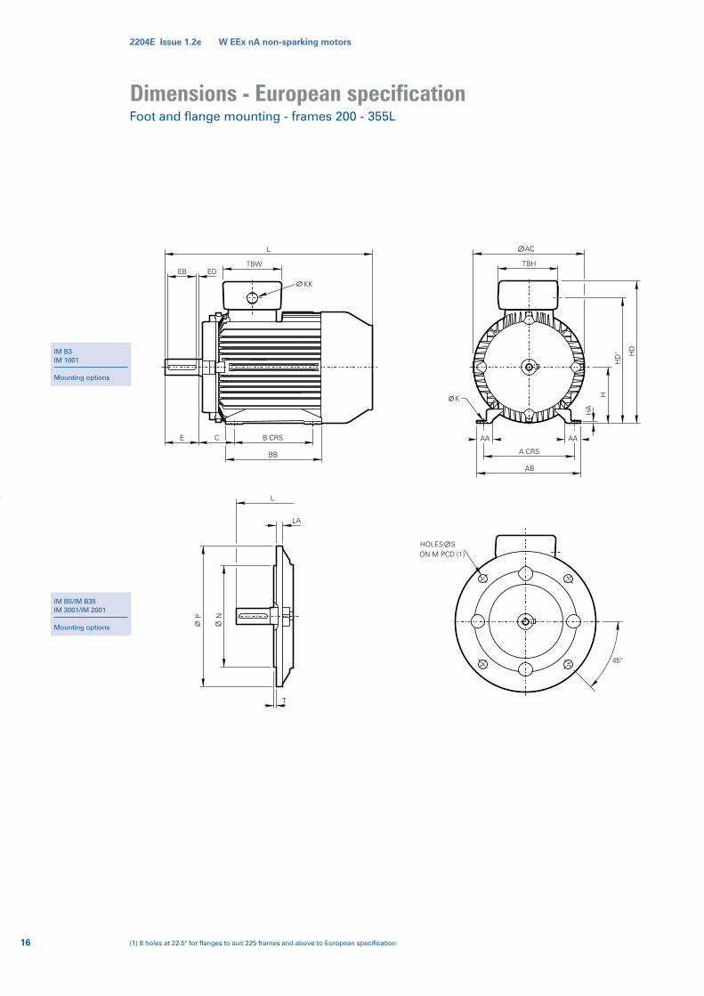
Dimensions - European specificationFoot and flange mounting - frames 200 - 355L
IM B3IM 1001
Mounting options
IM B5/IM B35IM 3001/IM 2001
Mounting options
16 (1) 8 holes at 22.5° for flanges to suit 225 frames and above to European specification

2204E Issue 1.2e W EEx nA non-sparking motors
W-UDF200LX
W-UDF225S
W-UDF225M
W-UDF250ME
W-UDF280SE
W-UDF280ME
W-UDF315SE
W-UDF315ME
W-UDF315M
W-UDF315L
W-UDF355S
W-UDF355M
W-UDF355L
Type
318
356
356
406
457
457
508
508
508
508
610
610
610
General Terminal boxA
305
286
311
349
368
419
406
457
457
508
500
560
630
B
133
149
149
168
190
190
216
216
216
216
254
254
254
C
200
225
225
250
280
280
315
315
315
315
355
355
355
H
M16
M16
M16
M20
M20
M20
M24
M24
M24
M24
M24
M24
M24
K
2 x M32 + 1 x M20
2 x M40 + 1 x M20
2 x M40 + 1 x M20
2 x M50 + 1 x M20
2 x M50 + 1 x M20
2 x M50 + 1 x M20
2 x M63 + 1 x M20
2 x M63 + 1 x M20
2 x M63 + 1 x M20
2 x M63 + 1 x M20
2 x M63 + 1 x M20
2 x M63 + 1 x M20
2 x M63 + 1 x M20
KK
787
875
915
985
1065
1070
1145
1215
1245
1315
1485
1605
1655
L(1)
74
70
70
79
83
83
89
89
89
89
100
100
100
382
426
426
482
540
540
597
597
597
597
710
710
710
AA AB
381
410
448
448
508
508
563
563
640
640
732
732
732
AC
359
349
374
419
438
489
482
533
533
583
626
686
756
BB
30
25
25
28
35
35
38
38
38
38
27
27
27
HA
501
550(2)
570
595(3)
655(2)
655(2)
845
845
875
875
975
975
975
HD
176
220
220
220
220
220
330
330
330
330
330
330
330
TBW
220
288
288
288
288
288
526
526
526
526
526
526
526
TBH
(1) For vertically mounted, shaft down motors see table on page 4 for increase in overall length due to the fitting of an impact cover.(2) add 25mm when cable entry is facing drive end(3) add 50mm when cable entry is facing drive end
TAPPED HOLE DH
TO DIN 332F
D
GD
G
Foot and flange mounting - frames 200 - 355L
787
845
885
985
1065
1070
1115
1185
1215
1285
1415
1535
1585
L(1)
W-UDF200LX
W-UDF225S
W-UDF225M
W-UDF250ME
W-UDF280SE
W-UDF280ME
W-UDF315SE
W-UDF315ME
W-UDF315M
W-UDF315L
W-UDF355S
W-UDF355M
W-UDF355L
Shaft
55
60
60
65
75
75
80
80
80
80
100
100
100
D
110
140
140
140
140
140
170
170
170
170
210
210
210
E
16
18
18
18
20
20
22
22
22
22
28
28
28
F
49
53
53
58
67.5
67.5
71
71
71
71
90
90
90
G
100
125
125
125
125
125
160
160
160
160
200
200
200
EB
5
10
10
10
10
10
5
5
5
5
5
5
5
ED
W-UDF200LX
W-UDF225S
W-UDF225M
W-UDF250ME
W-UDF280SE
W-UDF280ME
W-UDF315SE
W-UDF315ME
W-UDF315M
W-UDF315L
W-UDF355S
W-UDF355M
W-UDF355L
Type IM B5, IM B35 mounting
350
400
400
500
500
500
600
600
600
600
740
740
740
M
300
350
350
450
450
450
550
550
550
550
680
680
680
N
400
450
450
550
550
550
660
660
660
660
800
800
800
P
19
19
19
19
19
19
24
24
24
24
24
24
24
S
5
5
5
5
5
5
6
6
6
6
6
6
6
T
19
19
19
25
25
25
29
29
29
29
28
28
28
LA
4 po
le +
2 po
le
Type4 pole +
55
55
55
60
65
65
65
65
65
65
75
75
75
D
110
110
110
140
140
140
140
140
140
140
140
140
140
E
16
16
16
18
18
18
18
18
18
18
20
20
20
F
49
49
49
53
53
58
58
58
58
58
67.5
67.5
67.5
G
100
100
100
125
125
125
125
125
125
125
125
125
125
EB
5
5
5
10
10
10
10
10
10
10
10
10
10
ED
M20 x 42
M20 x 42
M20 x 42
M20 x 42
M20 x 42
M20 x 42
M20 x 42
M20 x 42
M20 x 42
M20 x 42
M24 x 50
M24 x 50
M24 x 50
DH
2 pole
17For tolerance details and notes - see page 23
10
11
11
11
12
12
14
14
14
14
16
16
16
GD
10
10
10
11
11
11
11
11
11
11
12
12
12
GD
444
488
510
535
595
595
744
744
776
776
874
874
874
HD1

2204E Issue 1.2e W EEx nA non-sparking motors
Dimensions - BS specificationFoot and flange mounting - frames 200 - 355L
18
IM B3IM 1001
Mounting options
IM B5/IM B35IM 3001/IM 2001
Mounting options
(1) 8 holes at 0° for flanges to suit 225 frames and above to British specification

2204E Issue 1.2e W EEx nA non-sparking motors
W-DF200LX
W-DF225S
W-DF225M
W-DF250S
W-DF250M
W-DF280S
W-DF280M
W-DF315S
W-DF315M
W-DF315L
W-DF355S
W-DF355M
W-DF355L
318
356
356
406
406
457
457
508
508
508
610
610
610
General Terminal boxA
305
286
311
311
349
368
419
406
457
508
500
560
630
B
133
149
149
168
168
190
190
216
216
216
254
254
254
C
200
225
225
250
250
280
280
315
315
315
355
355
355
H
M16
M16
M16
M20
M20
M20
M20
M24
M24
M24
M24
M24
M24
K
74
70
70
79
79
83
83
89
89
89
100
100
100
787
875
915
985
1030
1100
1145
1215
1245
1315
1485
1605
1655
L(1)
382
426
426
482
482
540
540
597
597
597
710
710
710
AA AB
381
410
448
448
508
508
563
563
640
640
732
732
732
AC
359
349
374
381
419
438
487
483
533
583
626
686
756
BB
30
25
25
28
28
35
35
38
38
38
27
27
27
HA
501
550(2)
570
595(3)
625(2)
655(2)
810
845
875
875
970
970
970
HD
176
220
220
220
220
220
330
330
330
330
330
330
330
TBW
220
288
288
288
288
288
526
526
526
526
526
526
526
TBH
Foot and flange mounting - frames 200 - 355L
787
845
885
985
1030
1070
1115
1185
1215
1285
1415
1535
1585
L(1)
W-DF200LX
W-DF225S
W-DF225M
W-DF250S
W-DF250M
W-DF280S
W-DF280M
W-DF315S
W-DF315M
W-DF315L
W-DF355S
W-DF355M
W-DF355L
Shaft
55
60
60
70
70
80
80
85
85
85
100
100
100
D
110
140
140
140
140
170
170
170
170
170
210
210
210
E
16
18
18
20
20
22
22
22
22
22
28
28
28
F
49
53
53
62.5
62.5
71
71
76
76
76
90
90
90
G
100
125
125
125
125
160
160
160
160
160
200
200
200
EB
5
10
10
10
10
5
5
5
5
5
5
5
5
ED
W-DF200LX
W-DF225S
W-DF225M
W-DF250S
W-DF250M
W-DF280S
W-DF280M
W-DF315S
W-DF315M
W-DF315L
W-DF355S
W-DF355M
W-DF355L
Type IM B5, IM B35 mounting
350
400
400
500
500
500
500
600
600
600
740
740
740
M
300
350
350
450
450
450
450
550
550
550
680
680
680
N
400
450
450
550
550
550
550
660
660
660
800
800
800
P
19
19
19
19
19
19
19
24
24
24
24
24
24
S
5
5
5
5
5
5
5
6
6
6
6
6
6
T
19
19
19
25
25
25
25
29
29
29
28
28
28
LA
4 po
le +
2 po
le
Type
55
55
55
60
60
65
65
65
65
65
75
75
75
110
110
110
140
140
140
140
140
140
140
140
140
140
E
16
16
16
18
18
18
18
18
18
18
20
20
20
F
49
49
49
53
53
58
58
58
58
58
67.5
67.5
67.5
G
100
100
100
125
125
125
125
125
125
125
125
125
125
EB
5
5
5
10
10
10
10
10
10
10
10
10
10
ED
M20 x 42
M20 x 42
M20 x 42
M20 x 42
M20 x 42
M20 x 42
M20 x 42
M20 x 42
M20 x 42
M20 x 42
M24 x 50
M24 x 50
M24 x 50
DHType
4 pole + 2 pole
For tolerance details and notes - see page 23 1919
10
11
11
12
12
14
14
14
14
14
16
16
16
GD
10
10
10
11
11
11
11
11
11
11
12
12
12
GD
TAPPED HOLE DH
TO DIN 332F
D
GD
G
D
(1) For vertically mounted, shaft down motors see table on page 4 for increase in overall length due to the fitting of an impact cover.(2) add 25mm when cable entry is facing drive end(3) add 50mm when cable entry is facing drive end

2204E Issue 1.2e W EEx nA non-sparking motors
W-DF80M
W-DF90S/L
W-DF100L
W-DF112M
W-DF132S/M
W-DF160M/L
W-DF180M/L
W-UDF200LX
W-UDF225S
W-UDF225M
W-UDF250ME
W-UDF280SE
W-UDF280ME
W-UDF315SE
W-UDF315ME
W-UDF315M
W-UDF315L
W-UDF355S/M/L
Bearing references and oil seals for horizontally-mounted motors only
European
W-DF80M
W-DF90S/L
W-DF100L
W-DF112M
W-DF132S/M
W-DF160M/L
W-DF180M/L
W-DF200LX
W-DF225S
W-DF225M
W-DF250S
W-DF250M
W-DF280S
W-DF280M
W-DF315S
W-DF315M
W-DF315L
W-DF355S/M/L
BS
All
All
All
All
All
All
All
All
All
All
2
4 up
2
4 up
2
4 up
2
4 up
2
4 up
2
4 up
2
4 up
2
4 up
Polarity
Bearings(1)
Drive end Non-drive end
Oil seals(2)
62042Z
62052Z
62062Z
62062Z
62082Z
63092Z
63102Z
6312
6313
6314
6314
6316
6314
6318
6314
6318
6316
6319
6316
6319
6316
6319
6316
6319
N316
N324
62022Z
62032Z
62052Z
62052Z
63052Z
63072Z
63082Z
6312
6313
6314
6314
6316
6314
6318
6314
6318
6316
6319
6316
6319
6316
6319
6316
6319
6316
6324
20 x 30 x 7(3)
25 x 35 x 7(3)
30 x 42 x 7(3)
30 x 42 x 7(3)
40 x 52 x 7(3)
45 x 60 x 8(3)
50 x 65 x 8(3)
60 x 80 x 8(3)
65 x 90 x 10(4)
70 x 90 x 10(4)
70 x 90 x 10(4)
80 x 110 x 10(3)
70 x 90 x 10(4)
90 x 120 x 12(3)
70 x 90 x 10(4)
90 x 120 x 12(3)
70 x 90 x 10(4)
90 x 120 x 12(3)
70 x 90 x 10(4)
90 x 120 x 12(3)
70 x 90 x 10(4)
90 x 120 x 12(3)
70 x 90 x 10(4)
90 x 120 x 12(3)
75 x 100 x 10(4)
115 x 145 x 14(3)
Drive end
15 x 24 x 5(3)
17 x 28 x 6(3)
25 x 37 x 7(3)
25 x 37 x 7(3)
25 x 37 x 7(3)
35 x 47 x 7(3)
40 x 52 x 7(3)
60 x 80 x 8(3)
65 x 90 x 10(4)
70 x 90 x 10(4)
70 x 90 x 10(4)
80 x 110 x 10(3)
70 x 90 x 10(4)
90 x 120 x 12(3)
70 x 90 x 10(4)
90 x 120 x 12(3)
70 x 90 x 10(4)
90 x 120 x 12(3)
70 x 90 x 10(4)
90 x 120 x 12(3)
70 x 90 x 10(4)
90 x 120 x 12(3)
70 x 90 x 10(4)
90 x 120 x 12(3)
75 x 100 x 10(4)
115 x 145 x 14(3)
Non-drive end
Bearings and greasingarrangementsBearings are pre-packed with a grease type
dependant on frame size and re-greasing
facility as detailed in table opposite:
Technical information:Mechanical
(1) Frame sizes 80 and 90 have bearings with CN clearances, frame sizes 100 to 355 have bearings with C3 clearance ‘medium’ series(2) Sizes given are in mm, and represent bore x outside diameter x widthMaterial: (3) Nitrile rubber (4) Silicon rubber
Standard and re-greasing facilities
Type Standardgrease
Re-greasingfacility
80 - 180
200 - 355
EA6 Polyurea
Esso Unirex N3
Available
Standard
Type
W-DF80-90
W-DF100-180L
W-UDF200LX
W-UDF225S
W-UDF225M
W-UDF250ME
W-UDF280SE
W-UDF280ME
W-UDF315SE
W-UDF315ME
W-UDF315M
W-UDF315L
W-UDF355S/M/L(1)
W-UDF355S/M/L(2)
Grease life expected at 80ºC bearing temperature x 103 hours
European
W-DF80-90
W-DF100-180L
W-DF200LX
W-DF225S
W-DF225M
W-DF250S
W-DF250M
W-DF280S
W-DF280M
W-DF315S
W-DF315M
W-DF315L
W-DF355S/M/L(1)
W-DF355S/M/L(2)
BS
22.0
26.0
12.6
12.6
11.3
11.3
11.3
11.3
9.4
9.4
9.4
9.4
5.0
9.4
Horizontal
3000 min-1
Vertical Horizontal
22.0
26.0
8.2
8.2
7.4
7.4
7.4
7.4
6.1
6.1
6.1
6.1
3.3
6.1
32.0
35.0
30.0
30.0
29.5
26.3
23.4
23.4
21.3
21.3
21.3
21.3
8.2
13.5
32.0
35.0
20.3
20.3
19.2
17.1
15.2
15.2
13.8
13.8
13.8
13.8
5.3
8.8
35.0
35.0
30.0
30.0
30.0
30.0
30.0
30.0
30.0
30.0
30.0
30.0
16.2
22.5
(1) DE = Drive End (2) NDE = Non-Drive End
35.0
35.0
27.8
27.8
26.0
23.6
21.3
21.3
20.3
20.3
20.3
20.3
10.5
14.6
35.0
35.0
30.0
30.0
30.0
30.0
30.0
30.0
30.0
30.0
30.0
30.0
24.5
30.0
35.0
35.0
30.0
30.0
30.0
29.3
27.8
27.8
26.0
26.0
26.0
26.0
15.9
19.5
Vertical Horizontal Vertical Horizontal Vertical
1500 min-1 1000 min-1 750 min-1Type
20

2204E Issue 1.2e W EEx nA non-sparking motors
Technical information:Mechanical
W-DF80M
W-DF90S/L
W-DF100L
W-DF112M
W-DF132S
W-DF132M
W-DF160M
W-DF160L
W-DF180M
W-DF180L
Maximum permissible external axial thrust and radial loads in Newtons (N)
Type
2
4
6
8
2
4
6
8
2
4
6
8
2
4
6
8
2
4
6
8
4
6
8
2
4
6
8
2
4
6
8
2
4
6
8
Poles
339
303
284
296
444
398
349
369
781
710
560
580
768
690
541
565
1355
1269
1186
1002
1253
1167
997
2168
2153
2022
1509
2144
2123
1973
1464
2711
2749
2575
2266
Load towardsmotor
Horizontal shaft Vertical shaft
Load away from
motor
539
503
484
496
684
638
589
609
1101
1030
880
900
1088
1010
861
885
1707
1621
1538
1354
1605
1519
1349
2663
2648
2517
2004
2639
2618
2468
1959
3274
3312
3138
2829
321
283
260
272
421
366
309
334
743
655
506
521
715
612
463
487
1266
1168
1074
869
1130
1035
858
2932
2659
2905
2389
2950
2982
2946
2435
3667
3830
3785
3469
Load towardsmotor
Shaft up
562
530
516
528
716
682
641
656
1159
1107
963
985
1170
1131
979
1003
1838
1779
1711
1556
1794
1718
1561
2002
1960
1777
1250
1951
1895
1669
1144
2465
2426
2166
1850
Load awayfrom motor
All figures are based on L10aah life of 20,000 hours
Axial and radial loads
521
483
460
472
661
606
549
574
1063
975
826
841
1035
932
783
807
1618
1520
1426
1221
1482
1387
1210
2497
2160
1977
1450
2151
2095
1869
1344
2665
2626
2366
2050
774
729
653
662
915
854
720
747
1295
1215
1145
1018
1295
1202
1141
1009
2114
2095
1997
1609
2068
1968
1600
3650
3785
3626
3316
3613
3738
3544
3233
4374
4556
4334
3979
Shaft down
Maximum permissible radial load
at end of shaft
(standard mounting)
362
330
316
328
476
442
401
416
839
787
643
665
850
811
659
683
1486
1427
1359
1204
1442
1366
1209
2437
2464
2410
1894
2455
2487
2451
1940
3104
3267
3222
2906
Load towardsmotor
Load awayfrom motor
21
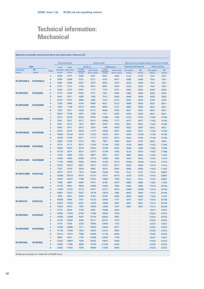
2204E Issue 1.2e W EEx nA non-sparking motors
Technical information:Mechanical
W-UDF200LX
W-UDF225S
W-UDF225M
W-UDF250ME
W-UDF280SE
W-UDF280ME
W-UDF315SE
W-UDF315ME
W-UDF315M
W-UDF315L
W-UDF355S
W-UDF355M
W-UDF355L
Maximum permissible external axial thrust and radial loads in Newtons (N)
2
4
6
8
4
6
8
2
4
6
8
2
4
6
8
2
4
6
8
2
4
6
8
2
4
6
8
2
4
6
8
2
4
6
8
2
4
6
8
2
4
6
8
2
4
6
8
2
4
6
8
Poles
5435
6058
6055
5781
6692
6770
6441
6729
7530
7640
7293
6640
9012
9391
9007
6505
10241
10846
10400
6268
9774
10582
10136
7443
10305
11190
10797
7337
10077
10958
10347
7398
10192
11060
10667
7055
10008
10872
10263
6118
12994
14038
14106
5779
12528
13148
13214
5595
12343
12936
13002
Horizontal shaft Vertical shaft
All figures are based on L10aah life of 20,000 hours
BSframe
Loadtowardsmotor
Loadaway from
motor
4775
5398
5395
5121
6122
6200
5871
6197
6998
7108
6761
6108
8418
8797
8413
5911
9579
10184
9738
5736
9112
9920
9474
6849
9965
10850
10457
6743
9737
10618
10007
6804
9852
10720
10327
6461
9668
10532
9923
5524
11454
12498
12566
5185
10988
11608
11674
5001
10803
11396
11462
5005
5531
5457
5183
5941
5935
5606
6084
6745
6673
6326
5837
8030
8311
7927
5472
8943
9423
8977
5101
8014
8704
8257
5921
8299
9050
8657
5654
7672
8419
7798
5664
8006
8715
8322
5050
7501
8207
7587
3136
8799
9387
9455
2326
7511
7523
7589
1734
7038
6980
7046
Loadtowardsmotor
Load awayfrom motor
5361
6121
6215
5941
7177
7371
7042
7082
8099
8463
8116
7209
9794
10311
9927
7352
11377
12157
11711
7355
11534
12524
12077
8957
12719
13810
13417
9082
13044
14131
13510
9154
12862
13971
13578
9164
13123
14229
13609
9692
17389
19143
19211
10050
18055
19533
19599
10396
18282
19794
19860
6021
6781
6875
6601
7747
7941
7612
7614
8631
8995
8648
7741
10388
10905
10521
7946
12039
12819
12373
7887
12196
13186
12739
9551
13059
14150
13757
9676
13384
14471
13850
9748
13202
14311
13918
9758
13463
14569
13949
10286
18929
20683
20751
10644
19595
21073
21139
10990
19822
21334
21400
Loadtowardsmotor
Load awayfrom motor
4345
4871
4797
4523
5371
5365
5036
6213
6213
6141
5794
5305
7436
7717
7333
4878
8281
8761
8315
4569
7352
8042
7595
5327
7959
8710
8317
5060
7332
8079
7458
5070
7666
8375
7982
4456
7161
7867
7247
2542
7259
7847
7915
1732
5971
5983
6049
1140
5498
5440
5506
Europeanframe
5125
5588
5536
5252
5963
5982
5648
6602
6868
6856
6501
6262
8163
8477
8087
5692
9260
9336
9336
5824
9136
9698
9216
6804
9443
10042
9630
6680
9121
9734
9312
6885
9482
10066
9640
6603
9207
9801
9367
-
-
-
-
-
-
-
-
-
-
-
-
Europeanframe
BSframe
5125
5588
5536
5252
5963
5982
5648
6602
6876
6856
6501
6262
8163
8477
8087
5897
9627
10182
9706
5795
8842
9386
8919
6804
9443
10042
9630
6680
9121
9734
9312
6885
9482
10066
9640
6606
9207
9801
9367
-
-
-
-
-
-
-
-
-
-
-
-
7541
7541
7541
7541
8202
8202
8202
8745
8921
8921
8921
8921
11342
11342
11342
8242
17105
17105
17105
9825
17423
17423
17423
11342
17414
17414
17414
11342
17414
17414
17414
11342
17414
17414
17414
11342
17414
17414
17414
12627
27533
27533
27533
12627
27533
27533
27533
12627
27533
27533
27533
Europeanframe
BSframe
7541
7541
7541
7541
8202
8202
8202
8745
8921
8921
8921
8921
14166
14166
14166
8921
14166
14166
14166
9503
17348
17348
17348
11342
17414
17414
17414
11342
20887
20887
20887
11342
20748
20748
20748
11342
20748
20748
20748
12627
27533
27533
27533
12627
27533
27533
27533
12627
27533
27533
27533
Maximum permissible radial load at end of shaft
Shaft up Shaft down Standard ball bearing Roller bearingType
W-DF200LX
W-DF225S
W-DF225M
W-DF250S
W-DF250M
W-DF280S
W-DF280M
W-DF315S
W-DF315M
W-DF315L
W-DF355S
W-DF355M
W-DF355L
22

2204E Issue 1.2e W EEx nA non-sparking motors
Dimensions – page notes
All dimensions in millimetres
Drain holes are standard on frames 160-355 andon request for frames 80-132
Please note that 80 frame motors are onlyavailable as terminal box right or left.
Cable entry can be arranged in any one of fourpositions at 90° intervals
No eyebolts on frame sizes 80 (all poles) and 90(6 and 8 pole)
Dimensions should not be used for installationpurposes unless specially endorsed
B5 mounted motors have suffix ‘D’ in the frame reference, eg W-DF132MVX-D and B35mounted motors have suffix ‘H’ in the framereference, eg W-DF132MVX-H
B14 mounted motors have suffix ‘C’ in the frame reference, eg W-DF132MVX-Cand B3/B14 mounted motors have suffix ‘H’ in the frame reference, eg W-DF132MVX-H
23
DOL starting(BS EN 60034-12 Design N)
Typical speed/current curve
Typical speed/torque curve
Star delta starting(BS EN 60034-12 Design NY)
Typical speed/current curve
Typical speed/torque curve
Performance data - page notes
220
1.82
346
1.16
365
1.1
420
0.95
440
0.91
500
0.80
550
0.73
Voltage
Factor
(IA) Starting current(IN) Full load current(MA) Starting torque or ocked rotor torque(MS) Pull up torque or run up torque(MK) Pull out torque or breakdown torque(MN) Full load torque
Torque/speed curves for specific motors canbe supplied on request
During the run up period in Star, there mustbe an adequate excess of motor torque overthe load torque. The change to Delta mustnot occur until the motor is near theoperating speed. Refer to Brook Cromptonfor running up against a load in excess of70% full load during Star Delta starting.
Performance figures are subject to IECtolerances. Performance figures are based ona 400 volt winding. To calculate IN on specialvoltages, multiply the IN at 400 volts by thefollowing factors:
130 to 180
230 to 250
300
350
450
550
680
Flange
j6
h6
h6
h6
h6
h6
h6
Dim N
+0.014
–0.011
+0.016
–0.013
+0.000
-0.032
+0.000
-0.036
+0.000
-0.040
+0.000
-0.044
+0.000
-0.050
Tol Limits
IEC 72-1Annex C.I.7 Option 1
60 and 80
95 and 110
130 and 180
Face
j6
j6
j6
Dim N
+0.012
–0.007
+0.013
–0.009
+0.014
–0.011
Tol Limits
IEC 72-1Annex C.I.7 Option 1
11 to 18
19 to 28
32 to 48
55 to 80
82 to 120
Shaft
j6
j6
k6
m6
m6
Dim D
+0.008
–0.003
+0.009
–0.004
+0.018
+0.002
+0.030
+0.011
+0.035
+0.013
Tol
British andEuropean
Limits
TAPPED HOLE DH
TO DIN 332
F
D
GD
G

Brook CromptonSt Thomas’ Road, HuddersfieldWest Yorkshire HD1 3LJ UKTel: +44 (0) 1484 557200Fax: +44 (0) 1484 557201E-mail: [email protected]: www.brookcrompton.com
Printed in Englandgh111/08/02 2204E issue 1.2e
© Copyright 2002. Brook Crompton. All rights reserved.
R o t a t i n g E l e c t r i c a l M a c h i n e s
Worldwide sales and service network
Every care has been taken to ensure the accuracy of the information
contained in this publication, but, due to a policy of continuous
development and improvement the right is reserved to supply products
which may differ slightly from those illustrated and described in this
publication


