dr. sataa al-bayati (10-11)
TRANSCRIPT

1
تغى الله انشحًن انشحٍى
Pumps & Pumping Stations-3rd
Class)المضخبث ومحطبث الضخ( Dr. Sataa Al-Bayati (10-11)
Dictionary:
Impeller = انذفاعح, suction= أيتصاصعحة أو , centrifugal = تناتزي, rotary= دواسج ,
Piston = Plunger = مكبس,Progressing = تقدم , Screw = لولب, Gear = تشط,
Submersible = غاطظ,Mounted = يشكة عهى حايم, Pneumatic = ًهىائ,hub=يحىس,
Positive displacement = الاصاحح الاٌجاتٍح ,Line shaft = عًىد يناونح عهىي,
Ejector = قارف, Regenerative = شجاعأعت , Multistage = يتعذد انًشاحم,
Vessel = وعاء, Lobe = نتىء يغتذٌش, affinity laws = قىانٍن انتقاسب,angular
,تقىٌح = booster,انغشعح اننىعٍح = specific speed,صاوي=
Pumps are needed for:
1. Lift water from a lake, reservoir or river to WTP.
2. After WTP to force the water into the mains & elevated storage.
3. In the system booster pumps is required at certain points to keep the
required pressure.
4. Raise the water from wells into a collecting basin (C.B.). Then from the
C.B. into the main pipe.
River → L.L.P. → W.T.P. → H.L.P. → Distr. System (booster P.)
(1) (2) (3)
Wells → Pumps → C.B.→ Pumps → Distr. System
(4) (4)
Classification of Pumps)تصنيف المضخبث(
1. Kinetic Pumps Kinetic pumps impart velocity and pressure to the fluid as it moves past or
through the pump impeller and, subsequently, convert some of that velocity
into additional pressure.

2
Fig.( 1) Classification of pumps. Hydraulic Institute [2].

3
1.1 Centrifugal Pumps ( Fig.2): All centrifugal pumps have one common feature: they are equipped with a
volute or casing. The function of the volute is to collect the liquid discharged
by the impeller and to convert some of the kinetic (velocity) energy into
pressure energy. It gives high head.
Fig. (2) centrifugal pump
1.2 Vertical Pumps They are equipped with an axial diffuser (or discharge bowl) rather than a
volute. The diffuser performs the same basic functions as the volute.
Classification of Vertical Pumps Vertical pumps were originally developed for well pumping. The bore size
of the well limits the outside diameter of the pump and so controls the
overall pump design.
1.2.1 Lineshaft Pump In lineshaft pump, the driver is mounted on the discharge head.
A typical lineshaft-driven, deep well pump is shown in Fig. (3). The bowl
assembly of the pump may contain as many as 60 stages, depending on the
well setting and on the discharge pressure requirements.

4
Figure(3) A lineshaft-driven vertical turbine pump. Hydraulic Institute [2].
1.2.2 Submersible Pump It (Fig. 4) is driven by a submersible motor. The motor is mounted below
the bowl assembly and is directly coupled to the pump rotor shaft.
Deep well submersible pumps, particularly useful for very deep (more than
180 m or 600 ft).
Short-setting submersible pumps, used for pumping shallow wells and
sumps or where the noise of a motor would be objectionable.

5
Figure (4) A vertical turbine pump driven by a submersible motor, Hydraulic Institute [2].
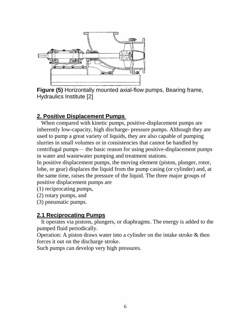
1.2.3 Horizontally Mounted, Axial-Flow Pumps They are high-capacity pumps and are typically used for flood control and
similar applications.
Horizontally mounted, axial-flow pumps are typically low-head pumps, and
larger sizes can have very high capacity—up to 30 m3/s (500,000 gal/min) or
more. Smaller pumps frequently have a bearing frame (Fig. 5) High-capacity
pumps operating with suction lift and located above the high-water level
may have a center hub that is equipped with water shaft seals and is accessed
through a manhole. The hub is never flooded with water.
Submersible, motor-driven, axial-propeller pumps are used in Europe for
flood-control applications.
The motor of these pumps may be filled with water and the bearings
lubricated with water. The pump and motor are inherently flood resistant.
Such pumping stations are compact, low in cost, and require no pump house.
6
Figure (5) Horizontally mounted axial-flow pumps, Bearing frame, Hydraulics Institute [2]
2. Positive Displacement Pumps When compared with kinetic pumps, positive-displacement pumps are
inherently low-capacity, high discharge- pressure pumps. Although they are
used to pump a great variety of liquids, they are also capable of pumping
slurries in small volumes or in consistencies that cannot be handled by
centrifugal pumps— the basic reason for using positive-displacement pumps
in water and wastewater pumping and treatment stations.
In positive displacement pumps, the moving element (piston, plunger, rotor,
lobe, or gear) displaces the liquid from the pump casing (or cylinder) and, at
the same time, raises the pressure of the liquid. The three major groups of
positive displacement pumps are
(1) reciprocating pumps,
(2) rotary pumps, and
(3) pneumatic pumps.
2.1 Reciprocating Pumps It operates via pistons, plungers, or diaphragms. The energy is added to the
pumped fluid periodically.
Operation: A piston draws water into a cylinder on the intake stroke & then
forces it out on the discharge stroke.
Such pumps can develop very high pressures.

7
Fig. (6) piston type
Plunger Pumps A representative plunger pump is shown in Fig. (7). It can be used for all
types of wastewater, sludge, scum, slurries, and clarifier and thickener
underflow. It can be applied for transfer and for metering service. Such
pumps are available in single and multicylinder models. The plunger
contains the crosshead, driven by a camshaft arrangement.
A plunger pump is equipped with single or dual ball lift check valves. The
dual design contains two ball check valves in series for each plunger on both
the suction and the discharge side. Two valves rarely hang up on foreign
matter at the same time, so if one valve is unseated the other continues to
operate properly until the foreign matter is flushed through without affecting
the pump operation.
The pump bodies and plunger housings are separate components, and the
plunger can be removed for replacement without disturbing the shaft
assembly, pump body, or piping. As with all positive displacement pumps,
plunger pump capacity is not altered by a changing discharge head. The
positive pressure exerted by the plunger clears plugged lines.
The pumps are, therefore, well suited for metering applications.

8
Figure (7) A plunger pump, G.M. Jones [3].
2.2 Rotary Pumps:
It is positive displacement pump use gears, lobes, screws, vanes. The
energy is added to the pumped fluid continuously.
Operation: It contains two rotating gears draw water into chamber & forces
it into discharge pipe.
2.2.1 Rotary Lobe Pumps It contains two elastomer-coated rotors that are driven by an integral gear
box and synchronized by timing gears. The rotors run without touching each
other or the casing. The liquid is drawn through the inlet port into the
pockets between the lobes and chamber walls. Because liquid cannot escape
between the two rotors, it discharges in the direction of rotation of the outer
lobes through the discharge nozzle.
Because of the "twisted" lobes, the pump discharges at a continuous and
smooth flow rate and is relatively nonagitating and nonshearing. The pump
is self-priming and can be run dry without damage from blocked or starved
suction inlets. It is suited for handling a wide range of sludge viscosities and
types. No check valves are required (provided the gearing prevents
backward rotation), and the pumping is not susceptible to rag buildup.
Elastomeric coatings for the lobes have been developed to pass hard solids
up to 120 mm (4 in.) in diameter, and the coating has good wearing life in
mildly abrasive duty. Where there is a high content of debris, an automatic
reverse mechanism can be provided to reduce operator attention.

9
At the head of the treatment plant (where sludges contain a low percentage
of solids but high grit content), urethane-coated rotors are recommended and
the pumps should be run at reduced speeds. Otherwise,
Buna N-coated rotors are used. The pumps are used for pumping sludge with
as much as 6% solids.
In summary, the initial cost is relatively high, but the advantages of
(1) quick, easy, inexpensive replacement of moving parts;
(2) compactness and space saving;
(3) high tolerance for rags and large solids;
(4) long life at low speeds; and
(5) self-priming make the overall life cycle cost attractive.
Fig.(8) Lobe pumps
2.2.2 Progressing Cavity Pumps A progressing cavity pump is designed specifically to transfer abrasive
and viscous fluids with a high solid, fiber, and air content. A hard steel
screw rotor rotates and orbits within an elastomer stator. The pitch of the
stator is two times the pitch of the rotor. As the rotor turns, it contacts the
stator along a continuous sealing line, creating a series of sealed cavities that
progress to the discharge end.
The cavity fills with liquid as it gradually opens and expands at the suction
end of the rotor. The trapped liquid is transported to the discharge end and is
then gradually discharged in an axial direction. Multistage pumps of up to
four stages are available for reduced wear from abrasives.
Progressing cavity pumps are used in wastewater treatment plants for
transferring all types of slurries and sludge, and they can pass solids with a
sphere diameter of up to 50 mm (2 in.). A "bridge breaker" can be added at
the front end of the pump to reduce the size of large solids. These pumps are
self-priming up to lifts of 8.5 m (28 ft), but they cannot be operated dry.

10
The flow is even and the shear is low. The pump is relatively easy to service,
but sufficient clear floor space must be available for dismantling and for
access to the rotor and the Cardan shaft.
Progressing cavity pumps are relatively low in cost, but stators and rotors
may have to be replaced frequently, especially if grit is present in the fluid.
To reduce wear, pump speed should be low (no more than 400 rev/min)
when pumping sludge or raw wastewater.
2.2.3 Screw Pumps In an Archimedes screw "pump" (a water lifter, really), a helical screw
rotates slowly and conveys water at atmospheric pressure trapped between
the flights of the screw up a trough or a pipe.
Screw pumps are high volume, nonclog, atmospheric-head devices that can
pump a variety of solids and debris in raw wastewater without screening.
There are two general types:
(1) the open screw, which rotates in a trough (Fig. 9-a), and
(2) the enclosed screw, in which both the screw and an enclosing cylinder
rotate (Fig. 9-b).
A major advantage of these pumps is variable pumping at constant speed,
because the output (up to design capacity) is controlled by the sump level
and equals the influent flow rate. The disadvantages are the inducement of
turbulence, the release of odors and other volatile substances in wastewater,
and the relatively high initial cost. But when comparing costs with those of
other types of pumps, consider the cost of the total system, including all
piping, wet or dry wells, screens, fittings, valves, variable-speed controls,
and other accessories as well as operating and maintenance costs. Note that
operators like screw pumps because the good ones, when properly installed,
are so trouble-free.
Fig. (9-a) An open screw pump

11
Fig. (9-b) An enclosed screw pump, G.M. Jones [3].
2.2.3.1 Open Screw Pump It (often called Archimedes screw) consists of a torque tube to which
spiral flightsare attached, a lower submerged bearing, an upper radial and
thrust bearing, a gear reducer (typically driven by an electric motor), and a
trough in which the screw rotates at a constant speed. The limiting speed
ranges from 20 rev/min in large pumps to 75 rev/min in small ones and
cannot be exceeded without water spilling over the top of the screw.
2.2.3.2 Enclosed Screw Pump Except for the following differences, the enclosed screw pump is similar
to the open type:
• Because the flights are welded to the outer cylinder, there is no slippage
(backflow). If the pump is stopped, the water is retained between the flights.
The lower bearing (a self-aligning set of rollers mounted above the high-
water level) is easily accessible.
The rollers carry most of the radial load.
• Because there is no slippage, the efficiency of the pump is very high and
stays high even at low discharge.
• A massive concrete structure is not needed.
2.2.3.3 Screw-Centrifugal Pump It has a deep, cone-shaped impeller with a demonstrated superior ability to
pass stringy material combined with low shear pumping action. These
pumps have been applied successfully in wastewater pumping stations with
heavy rag loads and variable speed drives, in treatment processes with a

12
need to preserve flocculated material, and in situations requiring fish
friendly operation.
2.3 Pneumatic Pump Compressed air is used to move the liquid in pneumatic pumps. In
pneumatic ejectors, compressed air displaces the liquid from a gravity-fed
pressure vessel through a check valve into the discharge line (Fig. 10) in a
series of surges spaced by the time required for the tank or receiver to fill
again.
The reduced density of a column of an air-liquid mixture is used to raise the
liquid in an air lift pump (Fig. 11). But because the water is not pressurized,
it is not really a pump. It is therefore not included in Fig. (1), and it should
be called a "water-lifting device."
Air Lift Pump (water-lifting device)
It consists of a simple tube immersed in the sump or wet well with a high
volume of low-pressure compressed air admitted at the bottom of the tube.
The reduced-density air-liquid mixture in the tube is raised by the static head
in the wet well, and it overflows into the open discharge channel (Fig.11).
The pump is extremely simple and can be constructed in the field. It is
suitable for raw wastewater, sludge, and sandy or dirty water.
The hydraulic efficiency is very low and rarely reaches 35%. For all except
very low heads, the pump requires large submergence.
Fig. (10) A pneumatic ejector, G.M. Jones [3].

13
Fig. (11) An air lift pump, G.M. Jones [3]. Pneumatic Ejector It is used for pumping low flow rates of wastewater at high heads (flow
rates to 140m3/h [600gal/min] at heads to 90 m [300 ft]), especially if the
flow rates are highly variable. The pump consists of a pressure vessel that is
allowed to fill by gravity until a predetermined level is reached (Fig. 10).
Controls are then operated to admit compressed air to the vessel. The high
pressure moves the liquid into the force main. When the chamber has been
emptied, the controls close the air supply valve and vent the air in the tank to
the atmosphere, which allows the next cycle to begin. The compressed air
may be supplied from a plant air system or from compressors installed on
location. Air receivers of adequate capacity for several cycles are sometimes
installed to provide for limited continuing operation of the system during
power outages.
Regenerative Turbine Pumps (special pumps)
They have long been recognized for efficiently producing low flows at
pressures much higher than those of centrifugal pumps of comparable size.
The liquid circulates in and out of the impeller buckets many times on its
way from the inlet to the outlet of the pump. Both centrifugal and shearing
action combine to impart additional energy to the liquid each time it passes
through the buckets. Pressure from the inlet in Fig. (12-a) increases linearly

14
to the discharge. The impeller runs at very close axial clearances with the
pump channel rings to minimize the recirculation losses, so these pumps can
only be used with clean liquids.
Pumps are made with capacities ranging from 0.13 L/s to more than 4.4 L/s
(2 gal/min to more than 70 gal/min) at heads ranging from 3 m to more than
120 m (10 ft to more than 400 ft).
Fig. (12) A regenerative turbine pump, (a) Impeller; (b) Section A-A. G.M. Jones [3].
Multistage Centrifugal Pumps Sizes are available for pumping from 0.08 to over 22 L/s (1.2 to over 350
gal/min) at corresponding heads of 150 to 260 m (350 to 600 ft). An
advantage of the multistage configuration is that pressures do not change
very much with a change in flow rate.
Summary of Typical Pump Applications The principal uses of the pumps shown in Fig. (1) are given in Table (1).
No distinction is made in Table (1) between clean water and dirty water
(with gritty material such as sand in suspension) because a clean water pump

15
can be made satisfactory for dirty water if it is constructed of abrasion-
resistant materials and if it is equipped with, for example, the appropriate
kinds of seals.
Table 1 Application of Pumps, G.M. Jones [3]. (For information)

16

17
Work & Efficiency of Pumps) الشغل والكفبءة(
Head, h = p/γ
If h = 1ft → p = γ h = 62.4Lb/ft3 × 1ft × (1ft
2/144in
2)
= 0.433psi
h = 1m → p = 9.8kN/m3 × 1m
= 9.8kN/m2 = 9.8kPa
Pressure → absolute pressure (AP)
→ gage pressure
1bar = 10m = 100kPa
Atmospheric pressure & Absolute Pressure relationship:
Fig.(13)
Total dynamic head (TDH) of a pump (total pumping head)
= static suction lift + static discharge head + friction head + velocity head
(negligible)
= Hs + Hd + HL
Fig.(14) Head terms used in pumping
(a) & (c). Total static head = static suction lift + static discharge head
(b) Submerged pump inlet (positive head upon intake)
Total static head (TSH) = static discharge head – static suction lift

18
(a) (b)
(c)
Fig.(14) Head terms used in pumping
Where:
HT = total static head
Hs = static suction lift
= difference in elevation between pump centerline & low level of supply
Hd = static discharge head
= difference in elevation between the pump & point of discharge
HL = headloss due to friction & fittings in discharge pipe
Friction head = hf + hL
hf → Darcy-Weisbach eq. or Hazen William eq.
hL = K(V2/2g)
K = ƒ (1/dia. of fittings) → Table (2)
Many types of fittings → Table (3)
ƒ (equivalent length of straight pipe) → Table (4)
HT
Hd
Hs
HT
Hd
Hs
p
HT
Hd
Hs

19
Table (2) Minor loss coefficient

20
Table (3) Energy Loss Coefficients for Flanged Pipe Fittings
Table (4) Approximate resistance of common Fittings, in equivalent feet of
straight pipe
System Head Curve)ينحنى اننظاو انشحنح( :
The relation between the piping system-flow.

21
HL = ƒ (dia., length, material, material condition, no. and type of fittings).
HL = ƒ (D, L, f)
Fig. (15-a) System headloss curve, HL-Q.
Q1 → HL1 from Darcy eq.
Q2 → HL2
↓
At Q = 0 →H = 0
H-Q parabolic → H = ƒ (V2) = ƒ (Q
2).
Fig. (15-b) System Head Curve, H-Q
TDH = H = HL + TSH
At Q = 0 → H = TSH
Note: No relation between TSH & Q, Why?
(a) System headloss curve (b) System head curve
Fig.(15) Head curves
Water Power)قذسج انًاء( :
Pw = KQH --- (1)
Where:
Pw = output power,
Q = flow,
H = total head,
K = constant = ƒ (γ & units).
For water at 20oC
K = 2.525 × 10⁻⁴
(hp, gpm, ft)
= 0.163 (kW, m3/min, m)
Power input to pump, Pp = Pw/e --- (2)

22
e =pump efficiency = ƒ (pump design, fluid, & operation) < 1
range ( 40 - 90%)
Power input to motor, Pm = Pp/e1
Where: e1 = motor efficiency < 1
For design purpose use e = 0.75 & e1 = 0.95.
Pm → Motor → Pp → Pump → Pw
motor input motor output pump output
pump input
Example (1):
Determine the water power, pump power, & motor load (power) for a pump
system designed to deliver 1.89 m3/min (500 gpm) against a total system
head of 50 m (164 ft).assume the efficiency of both pump & motor is 80%.
Solution:
γQH = (kN/m3).(m
3/s).m = kN.m/s = kW
Pw = KQH
= 0.163 × 1.89 × 50 = 15.4kw
= 2.525 × 10-4
× 500 × 164 = 20.7hp (1hp = 0.746kw)
Pp = Pw/e
= 15.4/0.8 = 19.25 kw
Pm = Pp/e1
= 19.25/0.8 = 24.06 kw (32.3hp).
***********************
The Centrifugal Pump
Action of the Centrifugal pump (Fig.16))يثذأ انعًم(:
Water in a rotating vessel وعاء()
h = s2/2g ------- (3)
Where:
h = height above level at center,
s = linear speed at point where h is measured.
Increase h with s indicates that these pumps produce high head.

23
Fig.(16) Water in a rotating vessel
Operation:
Water enters at casing center accelerated by rotating impeller through radial
& tangential velocity. The water leaving the impeller is slowed by the casing
& the flow velocity converted to pressure. The conversion is by casing
(volute pump).
Fig.(17) operation Basic parts of a centrifugal pump showing cover (left) and section of a centrifugal pump, commonly termed a volute pump because of the shape of its housing.
Fig.(18) Basic parts
Effect of Varying Speed)تأثيز تغييز السزعت(
D = impeller diameter
ω = angular velocity
Q = ƒ (ω)

24
h = ƒ (ω2)
Pw = ƒ (ω3)
For a pump (affinity laws):
Q1/( ω1 D13) = Q2/( ω2 D2
3) = --- ---- (4)
h1/( ω12 D1
2) = h2/( ω2
2 D2
2) = --- ----(5)
Pw1/( ω13 D1
5) = Pw2/( ω2
3 D2
5) = ---
Specific speed, ωs: the speed at which a pump in series will discharge a unit
flow under a unit head at max. efficiency. Q, h at emax
ωs = (ωQ1/2
)/h3/4
--- (6)
Where:
Q –gpm, h –ft, ω –rpm
ωs = 6.67 (ωQ1/2
)/h3/4
--- (7)
Where:
Q –m3/min, h –m, ω –rpm
High ωs more efficient than low ωs
For max. efficiency;
ωs = 1000- 4000 → centrifugal pump (radial p.)
4000- 7000 → mixed pump (radial & axial p.)
> 7000 → axial pump
Why we call a centrifugal pump, radial pump?
For a particular pump, the value of specific speed will vary from zero at zero
discharge to ∞ at zero head.
Characteristics of Centrifugal Pumps)خواص المضخت النببذة(
Q = ƒ (ω, h)

25
Fig. (19) Characteristic curves (H α 1/Q), ω = constant
h, Pw, η, vs. Q
e.g.: at emax → Q = gpm, h = ft, Pw = hp
Fig. (19) Characteristic curves of a centrifugal pump, ω = constant
Fig. (20) Pump Series Characteristic Curves, submitted by manufacturers.
For each pump, h, Q, Pw, e, D, & NPSH.
Ex.: If D = 12″, η = 72%, h = 108ft, Q = gpm, Pw = hp, & NPSH =
η

26
Fig. (20) Pump Series Characteristic Curves.
One casing → several impeller sizes.
→ expansion of an existing system.
Note: Cost of installation & alignment of large pumps may equal or exceed
that of pump itself.
The conditions that can alter pump performance:
a. Changes in impeller or casing geometry,
b. Increased internal pumping losses caused by wear, &
c. Variation of liquid properties.
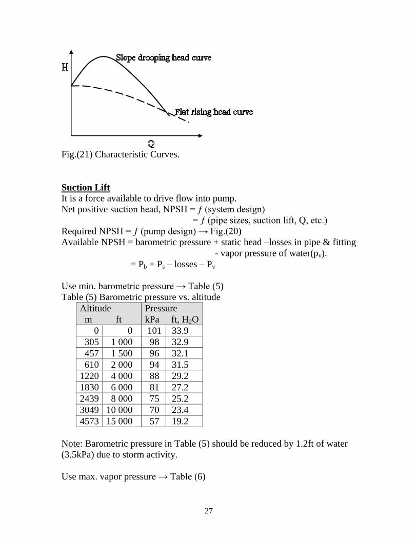
Classification of characteristic (Fig.21)
1. drooping head: rise to a max. h at an intermediate Q, then drop to a
lower shutoff,
2. rising head: rise to shutoff as Q decreases.
3. flat head: low variation in h with Q.
4. steep head: high variation in h with Q.
Moderately steep curve is preferable.
27
Fig.(21) Characteristic Curves.
Suction Lift It is a force available to drive flow into pump.
Net positive suction head, NPSH = ƒ (system design)
= ƒ (pipe sizes, suction lift, Q, etc.)
Required NPSH = ƒ (pump design) → Fig.(20)
Available NPSH = barometric pressure + static head –losses in pipe & fitting
- vapor pressure of water(pv).
= Pb + Ps – losses – Pv
Use min. barometric pressure → Table (5)
Table (5) Barometric pressure vs. altitude
Altitude
m ft
Pressure
kPa ft, H2O
0 0 101 33.9
305 1 000 98 32.9
457 1 500 96 32.1
610 2 000 94 31.5
1220 4 000 88 29.2
1830 6 000 81 27.2
2439 8 000 75 25.2
3049 10 000 70 23.4
4573 15 000 57 19.2
Note: Barometric pressure in Table (5) should be reduced by 1.2ft of water
(3.5kPa) due to storm activity.
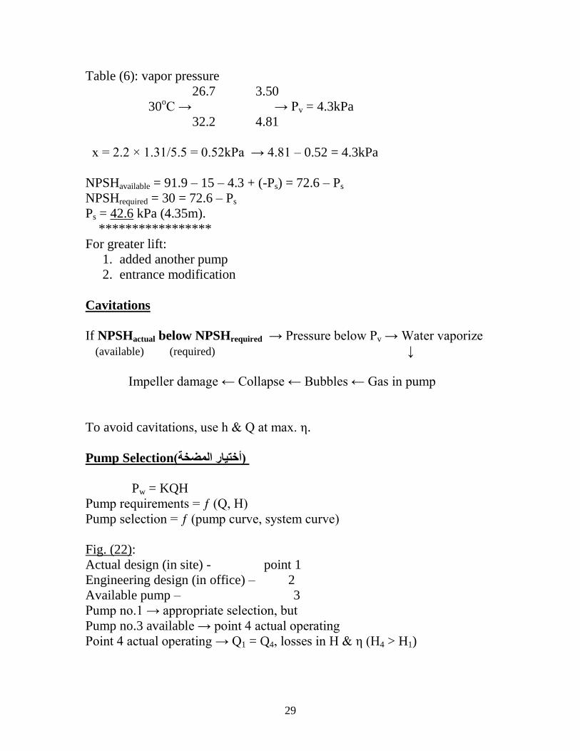
Use max. vapor pressure → Table (6)

28
Table (6) Vapor pressure of water vs. temperature
Temperature
oC
oF
Pressure
kPa ft, H2O
0 32 0.61 0.204
4.4 40 0.84 0.281
10 50 1.23 0.411
15.6 60 1.76 0.591
21.1 70 2.5 0.838
26.7 80 3.5 1.17
32.2 90 4.81 1.61
37.8 100 6.54 2.19
43.3 110 8.81 2.95
48.9 120 11.7 3.91
54.4 130 15.3 5.13
60 140 19.9 6.67
Example (2):
Assume that a water pumping station at 500 m elevation uses pumps
which require 30 kPa positive suction pressure (NPSH) when delivering
water at 30oC. What is the allowable suction lift of these pumps if the
entrance & friction losses are 15 kPa?
Solution:
NPSH = Pb + Ps – losses – Pv
Table (5): parametric pressure
457m 96kPa
500m → → 95.45kPa
610m 94kPa
43 x
153 2 → x = 43 × 2/153 = 0.55kPa → 96 – 0.55 = 95.45kPa
Storm activity: Pb = 95.4 – 3.5 =91.9kPa
29
Table (6): vapor pressure
26.7 3.50
30oC → → Pv = 4.3kPa
32.2 4.81
x = 2.2 × 1.31/5.5 = 0.52kPa → 4.81 – 0.52 = 4.3kPa
NPSHavailable = 91.9 – 15 – 4.3 + (-Ps) = 72.6 – Ps
NPSHrequired = 30 = 72.6 – Ps
Ps = 42.6 kPa (4.35m).
*****************
For greater lift:
1. added another pump
2. entrance modification
Cavitations
If NPSHactual below NPSHrequired → Pressure below Pv → Water vaporize
(available) (required) ↓
Impeller damage ← Collapse ← Bubbles ← Gas in pump
To avoid cavitations, use h & Q at max. η.
Pump Selection)أختيبر المضخت(
Pw = KQH
Pump requirements = ƒ (Q, H)
Pump selection = ƒ (pump curve, system curve)
Fig. (22):
Actual design (in site) - point 1
Engineering design (in office) – 2
Available pump – 3
Pump no.1 → appropriate selection, but
Pump no.3 available → point 4 actual operating
Point 4 actual operating → Q1 = Q4, losses in H & η (H4 > H1)

30
Fig.(22) Effects of Pump selection.
General Requirements for Pump Selection:
1. Capacity: satisfy the required discharge
2. Operation reliability: easy to start, sure of service in working, & does
not fail suddenly or cause trouble.
3. Efficiency: high efficiency
4. Power: low required power
5. Cost: cheap in initial cost, operation & maintenance cost, & long life.
System-Pump Curves
Cases:
1. both curves flat (Fig. 23a)
2. flat system-steep pump (Fig. 23b)
3. steep system-flat pump (Fig. 23c)
4. both curves steep (Fig. 23d)
Note: Case (3) is preferable: Q not varies much with H.
Fig.(23a) Both curves flat

31
Fig. (23b) flat system-steep pump
Fig. (23c) steep system-flat pump
Fig. (23d) both curves steep

32
Variation in Capacity)التغيزّ في السعت( Variable demand required variable pump capacity. Choose pump with
max. demand & let throttling to min. demand.
Pumps in Parallel
(Fig.24)
To increase capacity, Q.
This done by addition of characteristic curve:
Addition discharges of pumps at each head.
a. identical pumps (Q = 2Q1): AC = 2AB, CE = 2CD
b. dissimilar pumps(Q = Q1 + Q2): CF = CD + CE
At H > A:
Pump no. 1 dose not discharge, why?
Pump no. 2 discharge only.
For low Q use pump no.1
If pump no.2 used, pump no.1 never start due to high head, otherwise
use check valve.
At H ≤ A: Pump no.1 can be used for low Q
Pump no.2 medium Q
Pump no.1 & no.2 high Q
Pump no.1 low H
Pump no.2 high H
(a) Identical pumps. (b) Dissimilar pumps.
Fig. (25) Combined characteristic curves.

33
Multiple pumps & system curve:
More than two pumps (Fig. 26)
Pump no.1, % of max. design Q in the system
2 %
3 or (1+2) %
1 + 3 %
2 + 3 %
1 + 2 + 3 %
Intermediate Q → throttling, or pressure increases (system curve).
One selects a pump whose design point is close to operating point & that it
can be operate efficiently & economically over the required range.
Fig. (26) Combined characteristic curves for multiple pump installation.
Water Distribution Pumping )مضخبث التوسيع( High-lift pumps move treated water from water treatment plant into
distribution system.
Different sets of pumps may be needed against unequal pressures.
1. Source pumps: they located at the upstream end of the pipeline. They
draw water from reservoirs, tanks, & wells.

34
2. Booster pumps يضخاخ تقىٌح() , B.P.: they are located at some
intermediate point in the pipeline. They are used for high elevations,
& away areas.
________________ B.P._____B.P.____
↑ ↑ ↑ │ 2 │ 2
P P P
1
Pumps in series: used in booster pumps to increase head
Fig.(27) Pumps in series
Fig. (28) Connection of booster pump, US DEP. OF THE ARMY [3]

35
Well Pumps مضخبث البئز()
Shallow wells
Fig.(29) Shallow-well pump installation, R. Miller, et al [4].
Deep wells
They use vertical turbine pumps.
Multistage diffuser centrifugal pumps:
Series of small impellers.
Multistage pump chara. Curves (Fig.30)
It is same as pumps in series.
Each stage related to impeller.
Dia. 100mm – 750mm
H up to 5,000kPa (1,500ft water)
Q up to 100m3/min (30,000gpm)
Fig.(30) Series combination of pump stages.

36
Power for Pumping رة الضخ(قد)
Choice of prime Mover)أختٍاس انًحشك(
Electricity motor is used to drive pumps & there are many other movers.
Steam Engines)يكائن تخاسٌح(
Steam engines can be used in large plants & with cheap fuel.
Steam Turbines)عنفاخ تخاسٌح(
Impulse turbines are operated by the velocity of moving jet steam. They use
velocity & expansive force of steam.
Combined steam turbine & centrifugal pump advantages:
Small space, light foundations, simplicity, reliability & automatic oiling.
η for turbine 64 - 74%
with reducing gears 97.5 – 99%.
Diesel Engines)يكائن دٌضل(
High first cost, large space, need skilled operators, noisy in operation, cheap
fuel, & gearing is necessary.
Gasoline Engines)يكائن تنضٌن(
High fuel cost, but low first cost, therefore can be used for standby or
emergency service.
No gearing need. Wear in valves.
Electric Motors)يحشكاخ كهشتائٍح(
Cheap, & available
Pumping Stations
Location
Central location gives pressure uniformity in distribution system.
Small city: station on one side of high use area & storage tank on the other
side.
Large city: main station at central & substations or booster stations at such
points.
Figs. 31, 32, & 33 show layout of pump stations.

37
Fig.(31) River side intake
Fig.(32) Typical Pumping Station, US Army Corps of Engineers, [6]

38
Fig.(33) Typical Pumping Station, plan, US DEP. OF THE ARMY [5]
Capacity & Operation
Operation methods:
a. Water pumped directly into the system.
Characteristics:
- Variation in use by turning on & turning off.
- Interruption in service.
- Pressure fluctuations.
- Inefficiently & uneconomically.
b. Water pumped to a large elevated reservoir & discharged by gravity to
the distributed system.
Characteristics:
- Uniform pumping rates.
- Safety against interruption.
- Little head change.

39
- Efficient use of pumps but cost of elevated storage.
c. Water is pumped into the system with excess into elevated tank.
Characteristics:
- Max. efficiency for pumps
- Water for emergencies
- Costly
There should be sufficient space in the station to allow repair work & space
for installing additional pumps.
For proper O&M each unit should not be operated for more than 22
consecutive hours.
The station should be as close to the intake point as possible so that the
length of suction pipe is short. The suction pipe should be air tight, but the
water supply line has only to be water tight.
Auxiliary Pumping Stations (Booster Pumps))يضخاخ انتقىٌح(
Used for: 1. high ground elevation.
2. mains of inadequate size. The pump takes water from the largest
main & discharges into a pipe of the problem, with excess into an elevated
tank.
- This pump work automatically by;
a. A float rising & falling in the elevated tank.
b. A pressure pipe from the tank to the pump.
c. An altitude valve in discharge pipe from the tank closes when pressure
reaches a certain height.
d. Electrode type of control.
Many water utilities refuse to accept in-line pumps as satisfactory for
booster service & require construction of pressure equalizing storage
reservoir. Horizontal & vertical booster pumps then take suction from the
storage reservoir & return water at higher pressures to the mains.
Valves & Piping Details
- Foot valve: hold priming water in pump on suction side.
- Check valve: on discharge side; prevent backward surges.
- On outlet side of check valve a gate valve is required to permit repairs to
the check valve & allow throttling centrifugal pump.
- Pressure-relief valve on discharge side of a reciprocating pump. So that
stoppage will not cause damage to pump.
- Piping (suction & discharge)
Free from bends & size with low friction head.

40
- Pressure gauge-gives pressure condition.
- A meter measuring output of each pump.
Fig.(34) Centrifugal pump, showing location of gages for taking readings to calculate total hydraulic load, R. Miller, et al. [4].
Fig.(35) Wet pit pump
Reference: 1. E.W. Steel, & T.J. McGhee, 1979,"Water Supply & Sewerage", 5
th Ed., McGraw-HILL.
2. Hydraulic Institute , 1983, "Hydraulic Institute Standards for Centrifugal, Rotary, &
Reciprocating Pumps", 14th ed., 9 Sylvan Way, Parsippany, NJ 07054. www.pumps. Org 3. G.M. Jones (Editor-in-chief), 2006, "Pumping station design", 3
rd Ed.
4. R. Miller, et al, 2004, "Pumps & Hydraulics", Wiley. 5. US DEPARTMENT OF THE ARMY, 1992, WATER SUPPLY: PUMPING
STATIONS, TECHNICAL MANUAL.
6. US Army Corps of Engineers, 1998, “Water Distribution, Technical Instructions”, TI 814-03, Washington, DC.