draft cultural resource management and underwater
TRANSCRIPT
1
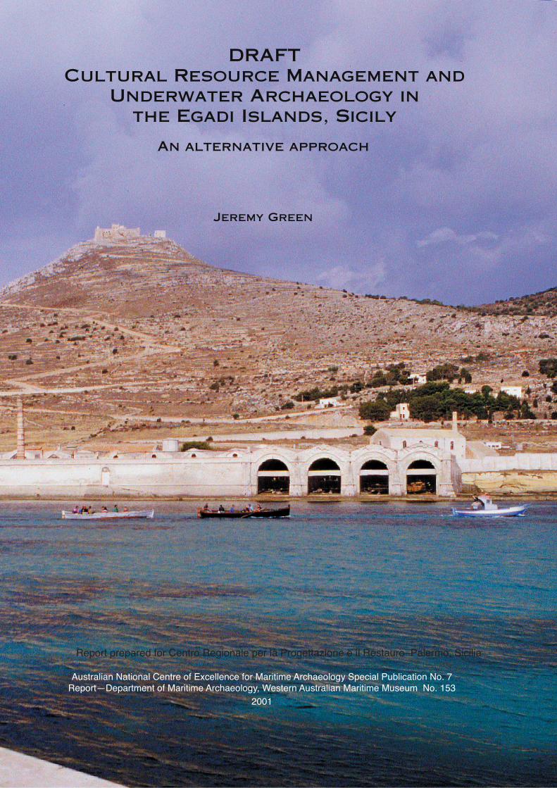
An alternative approach
Jeremy Green
Report prepared for Centro Regionale per la Progettazione e il Restauro–Palermo, Sicilia
Australian National Centre of Excellence for Maritime Archaeology Special Publication No. 7Report—Department of Maritime Archaeology, Western Australian Maritime Museum No. 153
2001
DRAFT Cultural Resource Management and
Underwater Archaeology in the Egadi Islands, Sicily
1
Cultural resource management and underwater archaeology of the Egadi Islands, Sicily:
A report prepared by Jeremy Green
This report has been prepared following a visit to Sicily in 2000 at the invitation of Dr Sebastiano Tusa to advise the Centro Regionale per la Progettazione e il Restauro–Sicilia on issues relating to underwater cultural resource management. The report reflects on the author’s experience in the Egadi Islands during a brief period (5–15 June) and outlines issues that may be relevant for future planning of maritime archaeological work in the region. The author should qualify these findings by acknowledging his limited experience of working in the region. It is likely that some of the issues dealt with in this report may suffer from a lack of understanding of the structure of the organisation and, more particularly, the author’s regrettable lack of understanding of the Italian language.
Note: this draft document does not include figures. These will be included in the final version of the report.
2
INTRODUCTION
The Egadi Islands are rich in underwater cultural heritage, having a long and important role in the maritime activities of Sicily and the Mediterranean. This underwater heritage—largely ancient shipwreck sites—has been extensively looted by divers and, as a result, much of what survives is badly damaged. It is probable that many other sites are known by locals, but, for various reasons, have not been reported to the authorities. In addition, there are likely to be many undiscovered sites—in both deep and shallow waters—which, if found and not adequately protected, will be under threat. The overall objective, therefore, is to find a means to ensure the long-term protection of all sites.
The immediate task is to set in place measures that, in the short and long term, will actively discourage the present practice of looting underwater sites. At the same time, the stakeholders, i.e. those with a vested interest in underwater heritage, must be persuaded to recognize the benefits of conserving these sites. Neither of these aims can be achieved without implementing a programme to change existing attitudes towards shipwreck material—a long, difficult and complex process. Attitudes can be changed, albeit slowly, and it is important that such programmes are undertaken to start the process at the local level, and can be supported through international efforts to protect underwater cultural heritage.
The three main avenues for effecting change are as follows: education; legislation and community participation. Each of these will be discussed in detail later. It must be emphasized at the outset, however, that the traditional method of relying on legislation alone to preserve shipwreck sites simply does not work. Legislative measures will only succeed if underpinned by education programmes to promote a change in public attitudes (i.e. of divers and non-divers alike) and to encourage community involvement. Legislation still has an important role to play in the management of sites. It provides the legislative framework for site management, defines the management process, encourages the positive aspects of preservation and, ultimately, makes provision for punishing miscreants.
This report sets out a management plan which can be used as a tool to define the programme for the Egadi Islands underwater cultural heritage management and to provide a structure and benchmarks for its implementation. It is not necessarily the only plan that could be developed, but it can be used as a starting-point in the overall process. The report is divided into three parts: the first outlines a management plan to deal with the underwater cultural heritage of the region; the second details a methodology to achieve the objectives of the plan; and finally, there is a section which makes recommendations on structure and strategic goals for the programme. As the primary objective of the work in the Egadi Islands is to preserve the underwater cultural heritage, strategies to achieve this are described in the management plan. It is intended, however, that the plan could also be used as a template to develop programmes for preserving the underwater cultural heritage of other regions. Since the author’s experience is largely based on work in Australia and Asia, there are some areas where the management strategies described may need to be adapted to suit the local conditions in Sicily. The methodology largely relates to survey methods and
3
techniques and is designed to be used as a practical guide to future archaeological work. The recommendations in the concluding section are intended as a guide for the management agencies and can be used to identify issues that need attention.
OUTLINE OF GENERAL OBJECTIVES
The general objective of this report is to develop a management plan for the Egadi Islands that will ensure the long-term protection of all of the underwater cultural heritage of the region. In formulating such a plan, and in the programme that may follow, it is important to ensure that a balance is achieved between the operation of management and the archaeological requirements. In other places, the author has too often observed archaeological needs being disregarded by management; and, conversely, the archaeological process ignoring management issues and the protection of sites. The management plan outlined here encompasses a multi-disciplined programme involving cultural resource management (CRM) and archaeological research. In devising a CRM plan, it is useful to adopt a step-by-step approach as follows:1. Identification of the issues2. Identification of the resource3. Identification of the stakeholders4. Establishment of the infrastructure (the organization and equipment)5. Location of sites6. Management of sites7. Education to create attitudes that understand the need for protection of sites8. Training9. Publication.Planning an archaeological research programme will involve devising strategies and allocating resources for fieldwork and scientific work related to the sites including:1. Geophysical survey to determine the extent of the area that is to be managed;2. Location of archaeological sites;3. Pre-disturbance recording of the sites; 4. Archaeological investigation and excavation of the sites; and 5. Education, which is the process of communicating the archaeological information
to a wide client group, including the general public, divers, locals, tourist industry and professionals.
CULTURAL RESOURCE MANAGEMENT
CRM implies a system whereby a resource is cared for in a way that ensures it is protected and preserved for the future. There is some confusion that CRM actually means that sites should not be disturbed, this being the only way to effectively preserve them. This argument has been used on a number of occasions, particularly in cases where the administrative structure is either under-funded or the practitioners are unfamiliar with archaeological techniques. A pragmatic approach to CRM is a
4
mix of in situ preservation and archaeological excavation. The CRM should uphold a philosophy which maintains that the sites, and the material in the sites, be made available for the public. It would be the responsibility of the managers to ensure that this process does not result in loss of material or the deterioration of sites.
While CRM is the process of looking after and preserving sites, it does not preclude excavation. On the contrary, in many cases, excavation is an effective management tool. There may be good archaeological reasons why a site should be excavated, but the reasons for any excavation need to be considered within the overall management strategy.
Through the careful integration of archaeological practice, resource management and museum and communication skills, sites can be brought to the attention of the public who can then be made aware of the significance and importance of the resource. The archaeological process is the method of gathering the information which provides, firstly, the scientific basis for the work, and which then disseminates information for the public. The public can then become involved in and participate in the management of the resource. There are examples of other programmes in which the public have become involved in the decision-making process. One has only to examine the conservation and The Green movements to be aware that public opinion can reverse quite strongly held attitudes. The basis of these movements has been to make the public aware of the long-term advantages of protecting resources and to seek public support in reversing existing policies and attitudes which threaten them. In a similar way, the CRM process should be aimed at preserving sites by changing public opinion through management strategies which draw on the continuing archaeological research.
The next three subsections will outline the main issues relating to CRM in Sicily, describing the different types of potential resources, and identifying the various stakeholders involved in underwater cultural heritage in Sicily. The fourth subsection will examine means of promoting public interest in, and regulating public access to, the maritime resource; and propose an appropriate management system. The final three subsections will touch upon some of the other concerns of a CRM programme, briefly discussing how the location and management of sites operate within the CRM process, and the role of education and training.
Identification of the issuesOne of the most important issues that a CRM programme for the Egadi Islands needs to address is how to effect a change in the existing negative attitudes of a group of looters and people who are not interested in preserving sites; and, at the same time, promote the positive attitudes of the group of people who are keen to preserve sites. These matters are discussed in the section Identification of Stakeholders (below).
Firstly, there is the need to establish efficient management practices, which enables the protection of sites to be set firmly within government and institutional policies, ensuring that the protection process has long-term stability.
Another crucial issue, is how to change existing perception that maritime archaeology is the realm of the academic, with little benefit filtering down from academe to the public sector. This widely held perception has, in many cases, a basis of truth and has resulted in a marginalization the general public and alienation of the
5
diving community, who see a limited ability to be involved in this type of work. The general public has little idea of the issues involved and their main exposure to the field is in the more sensational aspects of treasure hunting. This will be discussed further in the section Identification of the Resource.
Identification of the resourceThe resource—the underwater sites—in the Egadi Islands, as elsewhere in Sicily, falls into three main categories: sites that are known to the authorities; sites that are known to some people, but not the authorities; and sites that have not been found. Location of sites requires a complex strategy to be developed to find them. This includes negotia-tion with people who know of sites but are reluctant to reveal their location; searching for sites in shallow water and searching for sites in deep water.
Finding the location of sites requires a three-fold strategy: visually searching for sites using divers; the use of informants; and the use of remote sensing techniques. The visual search will be the most time-consuming and most difficult to manage, requiring training and a carefully prepared survey programme (discussed below in survey techniques and the planning of the overall programme). The use of inform-ants raises the sensitive issue of how to manage and influence individuals who know the locations of sites. Remote sensing is expensive and produces limited returns for the financial outlay. Assuming that many of the deep-water sites are probably known through bottom-trawling, remote sensing may be best employed to locate precisely the position of these approximately known sites.
The ultimate protection of sites requires the development of strategies that will ensure they are not disturbed. This can only be achieved when the majority of the stakeholders are agreed that these sites need to be protected because they can see the benefits of this for the Egadi Islands. Obviously, cultural tourism will play an important role in this process, since tourism is likely to be one of the most important industries for the islands now that the tuna industry is largely defunct. Recording the sites will require the cooperation of volunteers and will require infrastructure that will to help to ensure that the sites are properly managed and looked after in the future.
Once sites have been located, they need to be appropriately managed. Indeed, the management needs to be clearly defined before the sites are found (see Management of Sites below). The management plan should address all of the issues related to the long-term objectives of underwater cultural heritage management. This is still related to the identification of the resource, because individual sites will present different resource potentials.
This process should relate to the management plan, with precise stages, objectives and reporting structures. Initially, a three-year plan could be developed, with a clear objective that, by the end of the three years, the methods of management of the underwater cultural heritage should be defined, understood and, within reason, appropriately managed. The programme would involve one team carrying out visual survey of the sea-bed up to 30 m and investigating reported sites up to 50 m, and separate team conducting the remote sensing survey. I would suggest a plan that involved a concentrated visual search on a limited area in order to develop a
6
methodology. This is detailed in the section on methodology below.Assuming that t30 m is the normal maximum, practical (low-cost) archaeological
working depth for conventional SCUBA, and that one ignores sites at extreme depths (deeper than c. 200 m), archaeological sites of interest can be divided into three basic categories: 1. Shallow-water wrecks, i.e. up to 30 m; 2. Medium-depth sites, i.e. between 30 m and 60 m, in the workable, but high-cost,
range, and;3. Deep-water wrecks, i.e. in depths beyond 60 m, where Remotely Operated Ve-
hicles (ROV) or non-conventional or commercial diving technology would be required. It is assumed that visible shallow-water sites are all going to be known and dived
on by local people. The Egadi Islands region has a history of local diving and an active fishing industry, with access to SCUBA equipment. The medium-depth sites present the greatest potential because they will be better preserved, however, being more difficult to find means they are less likely to be looted but also makes the chance of their discovery more remote. The deeper water sites will probably be known through bottom-trawling, although they are less likely to have been exploited.
It is important to remember that most sites which have been heavily looted are still likely to contain a large quantity of archaeological information which can be extracted, but archaeological expertise will be required to access and exploit the information.
Identification of the stakeholdersThere are a wide variety of ‘stakeholder’ groups, who are either of direct or indirect relevance to this programme. It is important to identify each group; assess its potential impact (positive, neutral or negative); and establish a role for each one, or a management regime to address any potential threat that it may present. The various interest groups or stakeholders fall into a number of basic categories:
General Non-Diving Public;Recreational Diving Public (non-local); Diving Public (local); Commercial Salvage—Treasure Hunting Divers (amateur and professional); Commercial Dive Charter and Tourist Operators;Commercial—Other;
Non-Government Organizations (NGO)–GIASS (Gruppo Indagine Archeologica Subacquea Sicilia);
Government sector agencies with overlapping or associated responsibilities;Archaeological.These groups represent a wide cross-section of the community, including some
whose members present direct threats to the programme; some who have the potential to benefit the programme and some who are already fully committed. The management plan is designed to address the needs of each of these groups and, where necessary, propose ways that their attitudes can be influenced or changed. Change can only be effected when there are clearly demonstrated advantages to the group or groups involved, and this has to take into consideration the individual or group’s
7
characteristics. The following lists some issues for consideration in adopting a positive stance for stakeholders:1. In order to gain a financial advantage, dive charter operators may reveal site
locations to the authorities. They will see long-term benefit of ensuring sites are not looted, as a value-added experience will give the operator a commercial advantage;
2. Adopting a high-profile survey will demonstrate that, through survey, these sites will be discovered anyway so that cooperation will assist this process;
3. The amateur dimension of the Egadi Islands project is very important. By ensuring that this group is properly regarded and looked after, the programme can rely on a continuing diver-based support, which will help to counteract the negative group;
4. Consideration should be given to the concept of a reward for discovering or revealing the location of a site. The reward should be clearly gauged on the state of preservation of the site, thus discouraging the concept of looting sites and then revealing their presence for a reward. Care should be taken in the assessment of the sites. A number of countries have adopted the reward system, which does not necessarily need to be financial; it could be a civil award;
5. The results of the work should be publicly available. The proposed museum in the deserted tuna factory in Favagnana will make an ideal venue for this. It is essential that there is a forum where all members of the public (diving and non-diving) can see the results of the work and, more particularly, become involved in it.
GENERAL NON-DIVING PUBLIC It is difficult to assess the attitude of the general public towards underwater archaeology. Their understanding of the subject is likely to be limited, simply because archaeologists have not generally worked in the public forum. There are few popular books that give a true picture of the subject and the media is usually saturated with stories of treasure hunting. Museum displays, popular articles, publications, the Internet, wreck trails and television documentaries have all proven to be successful ways of enabling public access to information and encouraging public involvement.
RECREATIONAL DIVING PUBLIC (NON-LOCAL)This group represents one of the main threats to underwater archaeological sites in the region. As the group which is likely to have the largest impact on underwater cultural heritage, it is the most important one to influence. Within the group, there are possibly three sub-groups: a minority of dedicated divers who are extremely interested in wishing to help or be actively involved in the preservation of this heritage; a majority of divers who remove material from sites out of ignorance; and divers who purposely set out to loot sites for financial or personal gain. The first two groups can be encouraged to be involved in programmes and training courses along the lines of the Nautical Archaeological Society (NAS) Course. The third group is unlikely to be influenced by involvement in the programme. It is probably better to attempt to marginalize them, using protective legislation to curb their activities. It is possible
8
that, over a period of time, through the object lesson of the involvement of amateurs in a constructive and rewarding programme, members of this group may revise their strategy. However, in the long run, a pragmatic approach is to ensure that the group does not recruit new members that will continue the activities. In Egadi it is assumed that this recreational diving group are tourists from outside the Egadi area.
DIVING PUBLIC (LOCAL)This is a complex group, while small in number it is likely that they have an enormous amount of knowledge. It is apparent that there are local diving people who know of sites and who may or may not be willing to reveal their location. The key issue is to demonstrate to the whole community that having sites protected and implementing a positive programme will bring real benefits to the region. Thus, if local public opinion can be persuaded to support preservation, this will put pressure on local divers to support the programme.As for the locals who are unwilling to reveal their knowledge of sites, the reasons for such attitudes are complex: they may be deriving financial benefit from the knowledge (selling amphora); they may have a dislike of authority (the ‘dog-in-the-manger’ attitude); or they may consider it to be ‘their’ site, like a possession, of which they would lose ‘ownership’ by revealing it. If this group could be involved as inspectors and local representatives reporting to the central administration, they could play an important community role and gain recognition from this.
COMMERCIAL SALVAGE—TREASURE HUNTING DIVERS (AMATEUR AND PROFESSIONAL)This, in Italy overall, comprises probably only a small group, since it relies on public funding and, therefore, requires at least some form of legitimacy. The capital investment required for these types of operations makes it unlikely that they will operate in an area where they could be arrested and have their equipment confiscated. This group’s main impact is likely to be in extra-territorial waters where there is currently no legislation. While some treasure hunting within the Mediterranean continues to occur, it is unlikely that a major looting operation of a wreck site will take place because of the inevitable public outcry and international repercussions.
COMMERCIAL DIVE CHARTER AND TOURIST OPERATORS
Dive charter operators are a group who are likely to gain considerable financial benefit from a progressive CRM programme and, once convinced of its merits, would become strong advocates of protection. If sites can be protected and made available for operators to take their dive groups to visit, then they are likely to increase their business. The programme should involve the operators in understanding the nature of the sites through education and training. This would help the operators to improve their service to their customers. As new sites are discovered, they could participate in the process. This could work in various ways, e.g. operating on a similar basis to guides who take the public on tours of museums and ancient sites. Additionally, the operators could take on a role as inspectors, whereby they monitor sites and provide feedback to the Superintendent of the Centro Regionale per la Progettazione e il
9
Restauro–Sicilia. In addition, the programme would represent considerable ‘value-adding’ for any tourist to the Egadi Islands. Anything that is likely to engage the visitor and to enhance their visit will benefit the tourist industry. By enriching their experience—if positive—tourists will be encouraged to revisit the islands and to persuade others to come.
COMMERCIAL—OTHER
Several groups exist within this category, which includes local fishermen (tuna, line, net and trawler). This group usually has no incentive for or interest in involvement with underwater cultural heritage, other than that material recovered could potentially be sold, or that the knowledge of the position of a site could be revealed for a financial benefit. Obviously there are exceptions, but overall this is a difficult group to influence. Possible solutions may be a reward system for information on sites, or recruitment as inspectors, although the latter should be treated with caution as, unlike the charter operators, the fishermen will have little motivation.
NON-GOVERNMENT ORGANISATIONS (NGO) AND GIASS As a visitor to Sicily, lacking a thorough understanding of the role of GIASS, the author had difficulty in assessing its future function in a CRM programme. At the time of the visit, GIASS did not have permission to dive on any of the sites, so its role was obscure. It is understood that GIASS now has permission to dive on sites, which makes it, potentially, one of the key groups able to effect change. As GIASS members are paid by the regional administration, it is clear that their role should be one of co-ordination and leadership; however, at present they lack certain skills and experience. This group would benefit from advanced technical training in aspects of maritime archaeology, so that they could more effectively co-ordinate and lead future programmes. It may be that this group could also supervise or manage another, larger group, of volunteer divers, which would add to the effectiveness of the project. The training for GIASS members should include some form of qualification at the end of the course. This would provide an incentive to those members who wish to pursue a more significant leadership role within the organisation, as well as an assessment of the ability of the group so that they can be used to the greatest efficiency.
GOVERNMENT As noted previously, the Centro Regionale per la Progettazione e il Restauro–Sicilia is the key organisation with overall responsibility for underwater cultural heritage and this programme However, there are other government agencies which should be identified as having interests in this area. It is outside the parameters of the report to comment in this area following the author’s short visit, except to note the obvious and very beneficial co-operation between the Centro Regionale and the Guardia Financiale. It has been the author’s experience in Australia that the greater the inter-governmental co-operation that exists, the greater the public service profile. The State Museum of Western Australia has relationships with the government departments of Fisheries, Conservation and Land Management, Heritage, Marine Police, Transport (Marine),
10
Land Administration (Survey) and the Navy. Such relationships need to be formalized and this could be achieved by creating an advisory committee (see below, the section on Management under Structural Requirements).
ARCHAEOLOGICAL
The key members of this group lie naturally within the Centro Regionale, the universities of Trapani, and Palermo, together with other universities in Sicily and Italy that have interest in this area. The role of the archaeologist, in such a programme, is to oversee the archaeological programme. The CRM work, could be administered by an archaeologist or by a person with administrative expertise. Whatever course of action is taken in the eventual programme, there will be a need for clear archaeological direction. Obviously, this is a complex issue, and the author appreciates that this is exacerbated by the lack of qualified archaeologists in government positions in Sicily. However, it is vital that if this programme is to succeed, there should be somebody with archaeological expertise controlling it. If no archaeologist is available from within Sicily, then possibly one should be contracted for a period of time from outside Sicily, until locally trained archaeologists become available.
Structural requirementsThe structural requirements relate to the land- and underwater-based programmes. This section deals with the various ways that the programme can provide information for the visiting public and how this can benefit the Egadi Islands, together with management-related issues. Such programmes should attempt to work within, or be associated with, other programmes in the Egadi Islands related to tourism, heritage and the natural environment. The objective of these initiatives is to get information to the public.
LAND-BASED PROGRAMMES
ExhibitionExhibitions and museum-based displays are an important means of getting a message across to the public. As already proposed, the Floria Tuna Factory in Favignana will make an ideal site for a museum and centre to promote the shipwrecks programme of the Egadi Islands. It is understood that this programme is already in place. The facility to provide a public forum for the work will have important implications for many of the stakeholders that were discussed above.
Wreck trailsThe pedestrian public can be part of a wreck site programme through wreck trails. Starting in Favignana, a series of ‘look-out’ points can be set up at appropriate positions around the islands, which will provide information about nearby underwater sites. These information posts would link back to more detailed information in the exhibitions in Favignana. They can be integrated into a wider, land-based heritage trail programme, whereby the visitor, with a simple map in a brochure form, and signage, can follow a trail that takes them to all the important sites in the region. There is no
11
reason why significant wreck sites cannot be sign-posted to add a maritime dimension. Anchorages and known wreck sites can be indicated on the brochure and with signs at appropriate panoramic view-points. This can be promoted in the museum and, wherever possible, should involve local residents.
PublishingPrinted material in just about every form has been proven as effective means of promoting the principles of conservation and preservation of land-based or underwater cultural heritage. This can range from inexpensive A4 pamphlets or brochures, through to a medium-priced and more detailed descriptive history with site details, to large-format glossy publications. The pamphlets are the most effective as they are easy to produce, can be easily changed and provide basic information that can be provided for a large number of people.
MARINE-BASED PROGRAMMES
Allowing divers to have access to a wreck site is a risky exercise. It needs to be co-ordinated with a thorough educational and public relations programme. In the end, however, divers are going to access sites anyway, so the provision of education and information is crucial in order to maximise the likelihood that they will behave in an appropriate manner.
Wreck trailsProviding basic information to the diver will help to ensure that the individuals who dive on sites are informed of the correct position, the risks that the site presents, what is on the site and where things are located, together with what they may and may not do. This at least gives one the opportunity to influence the diver in a positive way. Hopefully, they can be made aware of the programme in the Museum and thus be encouraged to report anything unusual that they may see on the site. If divers have a positive experience when visiting a wreck, they are more likely to behave in an appropriate manner and even become more interested in preserving sites.
An example of a simple and effective way to inform and encourage divers in site-sensitive behaviour is to produce waterproof information sheets that the divers can use on their dive to locate and orient themselves on the site. These sheets should provide general information on each site, guidelines on appropriate behaviour and sources for further information. This could be co-ordinated by the museum-based Centro Regionale in Favignana and, again, should involve the locals as part of the programme.
In Western Australia and elsewhere, many sites have been marked with plinths or site markers. These markers serve several purposes: firstly, they establish the site is known; they also provide information about the site; they provide a focal point for co-ordinating diving on the site; and, finally, what the diver may or may not do on the site. Such aids are very useful as they establish an implied presence on the site as well as providing information for the diver. Plinths are simple and easy to construct. The information sheets that are mounted on the plinth are usually of bullet-proof glass,

12
with the information etched on the inside of the glass sheet.Another issue to be considered is that of the damage that can be caused when
boats anchor on a site. The programme could include the option of providing proper anchoring points for vessels visiting the site. The buoy could have information about the site and any restrictions that apply to it. If this system were to be implemented, the author recommends a screw anchor as the best anchoring system, as it provides great holding power in both the horizontal and vertical direction. This avoids having a long chain dragging on the site, because the buoy chain is almost vertical.
In some places, the diver pays to access the site, and is provided with a permit. This simplifies site management, since anybody found on a site is clearly breaching the rules. Obviously, legislation would need to be enacted to support this process. If the permit system is user-pays, then this has the advantage of generating revenue. It is debatable, however, whether a user-pays and revenue generation system is better than treating the situation on a trust basis. Divers in Western Australia have free access, but they are largely local divers. In the Egadi Islands, as most of the visitors are non-local, a user-pays system may be more appropriate.
Dive charterAs discussed above, the dive charter business could become an important component in the programme. Firstly, the operators need to be organised and agree to some code of practice. If they agree to cooperate with the programme, information about the sites could be provided to them and, through workshops, special arrangements could be developed to assist them in their operations. A decision would need to be made as to whether, in the long term, the charter operators could become inspectors. Experience in Western Australia has shown that the appointment of inspectors is worthwhile, as it provides an additional group of people who are authorised to administer the legislation. In most cases, the inspectors provide feed-back on the sites but they are also empowered to prosecute people who are breaking the law.
Experience in Australia has demonstrated that co-operation with dive charter operators and tourist agencies can be very helpful; and they, in turn, are generally extremely pleased with the information and assistance that is provided. The dive charter operators could also help to maintain the anchoring points for the sites, and monitor the sites for any recent disturbance. If the programme is successful it will be in their long-term interest to ensure the sites are not looted.
PublicationsThere is a wide range of publications that can be made available to the public (diving and general), some of which have already been mentioned As discussed, simple waterproof information sheets can be sold directly to the divers and charter operators. These can be taken underwater and would provide basic information, directions to find the site, its GPS co-ordinates and a site plan, obviously with information on what should not be done on the site.
As a complement to this, a small guidebook to the wrecks of the Egadi Islands could provide the basic information shown on the diver information sheet, but with more
13
details about the sites and the kind of material that one would find on the sites—such as amphora types and lead anchors—together with references to further reading. Again, the basic information and rationale as to why the protection of these sites is so important should be included. The book or booklet could be illustrated in colour and would make it an attractive and, possibly, revenue-generating project.
MANAGEMENT
Ultimately, the preservation of these sites will depend on the effectiveness of the management system. The hierarchical system would presumably have a project manager (an archaeologist), under whose direction would be various levels of specialists. This can probably best be illustrated in a tree-diagram. It is important to ensure that the system is well balanced. There is a need for good management of field staff and that the programme has access to senior management. It is also important that in the management of sites there is an awareness that archaeological programme is an essential part of the operation as it provides new and important information that will keep the programme dynamic.An important management arrangement would be the establishment of an advisory committee. It is inevitable that the administration of such a programme is likely to become difficult and contentious. If there is no clear involvement of the various ‘stakeholders’, they will be fragmented by different pressure groups. A way of avoiding such division is to create a formal ‘advisory committee’ which advises the Director of the Centro Region ale per la Progettazione e il Restauro–Sicilia. This allows the project director to bring issues to the advisory committee which can be discussed and recommendations tabled. Provided there is wide representation on this committee, it is unlikely that any resolution will be passed that does not have the majority support. This provides a double advantage of ensuring that issues are properly discussed and that decisions are seen not to be made by the agency, but rather by consultation in committee. This is a useful way of deflecting criticism of contentious decisions, since the agency has not necessarily made the decision.
Location of sitesThe methods of locating sites will be discussed in detail in the Archaeological Research section; however, it is important to examine how the process of locating sites will fit into the CRM process, as it requires carefully management. Also, achievable goals need to be established and a work programme formulated with a realistic time-frame. For example, in any given time a small team of divers can search a fixed area of sea-bed. Given that the three main Egadi Islands have a known length of coastline, what area would one expect to be able to survey within the five-year time-frame? What would one expect to achieve within this period, a 1% coverage, or a 10%, 20% or 50% coverage? In addition, what area of deep-water sea-bed could be realistically surveyed in a, let’s say, 3-week survey period?
The most significant requirement for this work is to establish a Geographical In-formation System (GIS)(for detailed explanation, see under Archaeological Research, Geophysical Survey, section on Creating the GIS). This will allow the archaeologists
14
and managers to record and assess the development of the programme and monitor the status of the sites. A GIS gives excellent visual representation of numerical and visual data, so that the progress of the project and the condition of each site can be easily monitored.
Management of sitesA CRM plan must give a clear definition of how the site management will operate. Sites need to be regularly inspected and the programme developed where the management of the sites has clearly identified objectives. Management needs to ensure that the site is stable and that it is not being adversely affected. This requires a periodic monitoring or inspection programme and probably cooperation with dive tour operators who, as part of the programme, could provide information on the current state of the site and report any changes.
Education and trainingEducation and training are dealt with together in this section, both forming an important element in the management plan. Education operates at three different levels: staff education and professional training, which provides work-based programmes to improve operational skills; training for commercial-sector operators, who would benefit from an educational programme to assist them in providing a better service for their clients; and visitor education, for the diving and non-diving public.
In the staff training, the objective would be to provide comprehensive skills for the GIASS group, as it will have the basic responsibility for implementing the management plan. The essential objective would be to train the GIASS group in techniques and methodology for the whole programme; which would include search and survey techniques, through to advanced maritime archaeological techniques and resource management training.
The CRM programme, following the basic training of GIASS members, would then move on to recruit local commercial-sector operators—in both the dive charter and the normal tourist area—who would be interested in co-operating with the programme. With the identification of additional interest groups, a series of workshops could be conducted to involve them in the programme.
Training and education programmes could be run for visiting tourist-divers, to assist the programme. These could operate on the lines of the Nautical Archaeological Society (NAS) Training Programme. They could be conducted in conjunction with the local tourism industry, with mutual benefits to all parties.
ARCHAEOLOGICAL RESEARCH
15
IntroductionIt must be remembered that the main focus of this project is the scientific field of archaeology. The management plan, discussed above, is a method whereby the resource is preserved and protected. The resource can be managed without a scientific study, but this would lead to a somewhat sterile programme, because it would not provide for accessing the important archaeological information which enlarges our understanding of the past. The objective of the archaeological research is, therefore, to reveal as much about the past as possible, within a carefully managed, practical programme. There is no point in starting a project without the resources to complete the work, conserve the material, and ensure that the material is properly looked after and displayed. Therefore, the archaeological work exists within the management strategy.
In the first part of this report, a management plan has been outlined, which identifies a wide range of interest groups that can be involved in the overall programme. The objective is to involve all these individuals and groups positively in the programme. Some will have a passive involvement, such as recreational divers who simply visit sites; whereas others will become involved in the programme, in assisting in the management or in the archaeological work. This approach attempts to ensure that the passive group does not damage or destroy the resource but enjoys it, while the active group are directed in a positive way to provide assistance to the programme.
The objectives proposed for the Egadi Islands research programme are as follows: to assess the selected area; to conduct a survey programme to investigate the area and locate sites; and, in time, to conduct limited excavation on selected sites. It should be reiterated that while many of the known sites have been looted, even very badly looted sites can reveal immense amounts of information, for very little cost or effort. Therefore, the research programme needs to address the issue of known sites and how to assess their significance. Ideally, if new sites can be found, they can be properly protected and investigated, and then integrated in an overall programme. Thus, survey is the first major part of the research programme and a description of the various methods of scientific surveying takes up the second part of this report.
Excavation is not dealt with in detail in this report and will be dealt with in a separate report to be developed at a later date.
The survey process is divided into two phases: defining the search area using geophysical survey techniques (establishing a GIS); and conducting an archaeological survey, which in itself is a dual process. The first stage of the archaeological survey involves a search of those areas defined in the geophysical survey. This is followed up, in the second stage, by a site survey, which is a more detailed scrutiny of any sites located from the archaeological search. Various remote sensing techniques (described in the following sections) may be used at all stages of survey. While the emphasis in this report is on scientific means of finding sites, the human element of research is equally important. Such methods include archival research; examining the written records relating to sites and oral history relating to the knowledge local people may have of sites.
Geophysical survey
16
INTRODUCTION
For the purposes of marine work, geophysical survey is the process of recording data relating to the ocean, sea-bed and coastline and incorporating this into an overall plan of the potential areas to be investigated. The objective is to record these details in a graphical format which will help in plotting sites, planning search and survey, and developing Geographical Information Systems (GIS) (see Creating the GIS below) which can be used for archaeological and management purposes.
Survey methods have radically changed in recent years and, in May 2000, an important change occurred which dramatically changed the nature of all marine surveying. Originally, the Global Positioning System (GPS) introduced the possibility of locating position anywhere on or above the surface of the Earth, using a small hand-held system that provided three-dimensional location to an accuracy of about 200 m. Accuracy is a complex issue, but essentially the accuracy of position refers to the standard deviation. The system was capable of providing a more accurate position, but the United States (US) government, which controls the GPS satellites, introduced an intentional error or dither (referred to as Selected Availability (SA)) into the system to reduce the position accuracy to about 200 m. It was possible to get round SA using a more sophisticated differential system, which increased the accuracy to about 2 m. On 1 May 2000, the US turned off SA, which now means that with a standard off-the-shelf GPS, the theoretical position accuracy is 1.8 m. This makes standard surveying possible for all survey work with just a GPS, and thus makes redundant most conventional surveying techniques. However, the introduction of very precise position-fixing brings with it a number of new problems, particularly the issue of the map datum, which will be discussed in more detail below.
The geophysical survey process is, firstly, to create a GIS of the area combining all available existing information. Once a survey area and finally conducting remote sensing and other types of archaeological survey of the area.
CREATING THE GISAs noted earlier, the most significant requirement for the location and management of sites is to establish a GIS (Geographical Information System). A GIS is essentially a computer-based system that enables the layering of a variety of different sorts of information. For example, one could have a GIS of a region that would have maps, aerial photographs, site location database, archaeological site plans and artefacts integrated in the system. The user could then select all the water shallower than, let’s say, 10 m; select all the wreck sites in this area; and display all the sites with a particular type of amphora. The GIS can assist the archaeologists and managers in recording and assessing the development of the programme and will help to monitor the status of the sites.
The maps available for marine survey work will generally include Admiralty charts and topographical maps. The Admiralty charts provide some information about the sea-bed, but usually at a scale that is not adequate for archaeological survey work, whereas the 1:100000 topographical maps are at a good scale but have no underwater information. These maps can be scanned and then registered so that they can be shown
17
on the GIS in their true geographical space, or may be available in digital form. Registering or geo-referencing is the process whereby each pixel of the graphic image is located in its correct geographical coordinate. Usually such files are geo-tiff files which have the geographical information included in a header in the file, or normal tiff files with an ancillary world file which has the geo-referencing information.
A further source of potentially useful information is aerial photographs (particularly high-quality colour) which can be scanned and used in defining shallow water search areas. However, it is often difficult to correctly geo-reference these files, since precise survey information is required of known features on the photographs. Sometimes, for areas where the accuracy is not critical, the photographs can be geo-referenced using geographical features on the photographs, such as headlands, rocks, etc. that can be identified on charts and, thus, have relatively accurate geographical coordinates.
It is possible that some form of digital cartographic information may be available of the area being surveyed, and while digital information is a rapidly developing field, it is likely that much of the existing information will need to be converted to digital format. Since much of the work will be required at relatively low accuracy, the problem of converting information should not be too complex.
With the GIS information thus established, it is then necessary to decide on the area to be searched and the methods that can be used to search. If there is not adequate information on the depths and sea-bed in general, it may be necessary to carry out a small- scale bathymetric survey, possibly with just an echo sounder and GPS. However, the decision-making process is likely to be complex and will depend on the type of survey likely to be undertaken. For example the decision-making process will be dif-ferent for deep-water survey work, where divers are likely to be involved, compared with shallow-water survey where divers can be easily and economically utilised. In reality, some sort of mix between the two will usually be used.
DEEP-WATER SURVEY
Deep-water geophysical work is likely to involve a range of remote sensing devices. It is unlikely that detailed hydrographic information will be required or available, and survey will probably involve a mixture of remote sensing options to locate and identify potential archaeological material. The most complex problem will be in differentiating natural underwater features from archaeological sites. Almost certainly, some form of Remotely Operated Vehicle (ROV) will be required to inspect likely targets.
SHALLOW-WATER SURVEY
In the case of shallow-water geophysical work, where one plans to use divers for inspection or survey, it is usually necessary to have detailed underwater topographical information. In this situation, the decision-making process is more complex. It is possible that one could simply conduct a bathymetric survey of the proposed search area, prior to deploying either remote sensing equipment or divers. It is, however, essential to have a clear idea of what the sea-bed is like, prior to deploying expensive and vulnerable remote sensing equipment at depth, or putting divers into the water where the depth is likely to be unpredictable. There is always a danger that the
18
equipment will become entrapped or damaged. If divers are to be employed then a clear understanding of the depths and the topography will assist in the dive planning and efficiency.
SURVEYING AND LAY-BACK
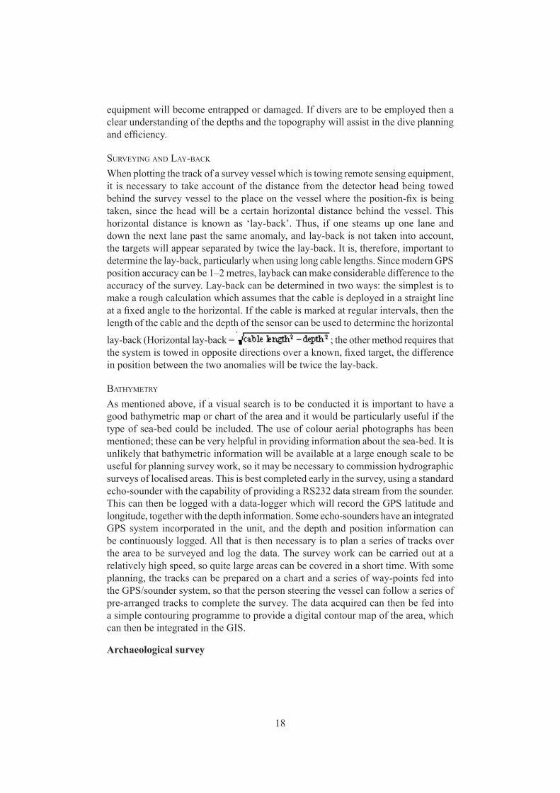
When plotting the track of a survey vessel which is towing remote sensing equipment, it is necessary to take account of the distance from the detector head being towed behind the survey vessel to the place on the vessel where the position-fix is being taken, since the head will be a certain horizontal distance behind the vessel. This horizontal distance is known as ‘lay-back’. Thus, if one steams up one lane and down the next lane past the same anomaly, and lay-back is not taken into account, the targets will appear separated by twice the lay-back. It is, therefore, important to determine the lay-back, particularly when using long cable lengths. Since modern GPS position accuracy can be 1–2 metres, layback can make considerable difference to the accuracy of the survey. Lay-back can be determined in two ways: the simplest is to make a rough calculation which assumes that the cable is deployed in a straight line at a fixed angle to the horizontal. If the cable is marked at regular intervals, then the length of the cable and the depth of the sensor can be used to determine the horizontal
lay-back (Horizontal lay-back = ; the other method requires that the system is towed in opposite directions over a known, fixed target, the difference in position between the two anomalies will be twice the lay-back.
BATHYMETRY
As mentioned above, if a visual search is to be conducted it is important to have a good bathymetric map or chart of the area and it would be particularly useful if the type of sea-bed could be included. The use of colour aerial photographs has been mentioned; these can be very helpful in providing information about the sea-bed. It is unlikely that bathymetric information will be available at a large enough scale to be useful for planning survey work, so it may be necessary to commission hydrographic surveys of localised areas. This is best completed early in the survey, using a standard echo-sounder with the capability of providing a RS232 data stream from the sounder. This can then be logged with a data-logger which will record the GPS latitude and longitude, together with the depth information. Some echo-sounders have an integrated GPS system incorporated in the unit, and the depth and position information can be continuously logged. All that is then necessary is to plan a series of tracks over the area to be surveyed and log the data. The survey work can be carried out at a relatively high speed, so quite large areas can be covered in a short time. With some planning, the tracks can be prepared on a chart and a series of way-points fed into the GPS/sounder system, so that the person steering the vessel can follow a series of pre-arranged tracks to complete the survey. The data acquired can then be fed into a simple contouring programme to provide a digital contour map of the area, which can then be integrated in the GIS.
Archaeological survey
19
SEARCHING FOR SITES
Archaeological survey is the investigation of sites that have archaeological remains or potential for archaeological material. Survey should involve the recording of all archaeological detail, from ancient to modern. Often, such surveys involve regional studies, where the area is too large to survey completely at any one time, and strategies need to be developed to conduct the work. This may involve selecting sites with a high potential for remains or investigating particular areas known to have sites. What follows describes the various methods of searching for archaeological sites, including remote sensing and visual search techniques.
Position fixingAs all sites need to be precisely located, the obvious choice for position fixing is the GPS. As mentioned above, since 1 May 2000 SA has been turned off, giving increased accuracy of position using a GPS. With SA turned off, position accuracy for small hand-held systems (capable of displaying 3 decimal points in minutes) is about 2 m. Given current prices, of a few hundred dollars, the GPS is an extremely useful instrument for a wide range of surveying techniques. The only way improve the accuracy of a GPS is to use a differential system with a high-precision GPS unit, which will provide sub-centimetre accuracy, but it is both complex and expensive.
Again, the advent of accurate GPS presents interesting opportunities to improve the recording of searches, either by deploying the GPS on the surface support vessel or by developing a waterproof GPS that can be used on the water surface. An even more revolutionary method is to make the system completely watertight and run an external antenna on the surface connected to the GPS by cable. In this situation, provided the diver is not too deep or there is not too much current, divers can record underwater features and use the navigation facilities that GPS provides.
In general two situations exist where it is necessary to locate position at sea. The first is where a particular site has been located, and its position needs to be determined accurately for future relocation. Using a GPS, either a large number of position fixes can be taken by the survey vessel anchored over the site to locate its position as accurately as possible, given the movement of the vessel; or some form of stable buoy can be established over the site and a single GPS measurement made to the buoy. Another method would be to use the diver-operated GPS, as discussed above. The other situation is where one is moving over the surface of the water or through the water, say towing some form of search detector system, and the search path needs to be known to ensure that the survey is providing adequate coverage. In this moving situation, position needs to be determined rapidly, in order to keep pace with the survey, but extreme accuracy may not necessary (as discussed above in the Geophysical Survey section).
DatumNow that the ordinary GPS system is accurate to a few metres, it is essential that the user understands the significance of the datum the GPS receiver is using. This is particularly important because the local Italian datum is approximately 100 m different from the WGS 84 system used in most survey work. This means that if you
20
plot a position recorded on a GPS using WGS 84 on a chart using the Italian datum, the position will be 100 m from the true position. Most national datum have been progressively revised over the years, so there are often a number of different datum systems; however, there is a current trend for all national datum to be redefined so that they approximate (within centimetres) to the WGS 84 system. Charts and maps, however, may be drawn in WGS 84 or in any number of versions of the local datum. For this reason, great care is needed to ensure that the GPS datum is recorded when recording position and that the chart datum is also known. Additionally, any future work will need to know what datum was used for the recording.
Most GPS units have a variety of different datum built into the system—often a hundred or more—so that the unit can be set in any particular datum. It is strongly recommended that all recording and survey work is carried out in WGS 84. It is relatively simple to change the datum later and ensures consistency.
Side-scan sonarCurrent high definition side-scan sonar is probably the most effective method of searching the sea-bed for wreck sites. These sonar systems, which have computer-driven software, have the ability to incorporate GPS information and magnetometer data making them an extremely versatile system. Some systems can operate at dual-frequencies, usually about 120 KHz provides large-scale survey over 500 to 1000 m ranges and around 600 KHz provides high accuracy surveys resolving about 10 cm objects at ranges up to about 100 m.
Side-scan sonar provides an acoustic view of the sea floor, on either side of the tow-fish. This is achieved by transmitting a narrow focussed beams of sound from either side of the fish. These beams have a fan-shape, narrow in the longitudinal direction and wide and fan-shaped in the lateral. Sound strikes the sea bed at progressively greater distances from the tow-fish and these signals are then radiated back and picked up by the tow-fish transducers. Using time dependent gain, it is possible to amplify the distant reflections sufficiently so that the sound display is uniform from the closest point to the most distant. The result is an acoustic picture of the sea-bed on either side of the tow-fish; in normal mode strong reflections are bright and shadows are dark. Tests show that sites in zero visibility situations can be resolved with high accuracy and certainly the system can be used for preliminary site survey work before divers are put into the water (see below).
It is possible to measure the height of a sonar target by the length of the shadow cast by the object. The calculation is quite simple and merely requires the height of the fish above the sea-bed, and the position and length of the shadow (see Fig. xx).
Side-scan sonar is only really useful in locating sites that lie on flat sandy sea-bed, where the site has some noticeable relief. Where the sea bed is rocky, sites are difficult to differentiate from the rock formations. In some cases, side-scan of areas which have mixed rock and sand can be used to delineate search areas and define areas that need to be surveyed with other forms of remotes sensing or by visual means.
Because the side-scan images that are generated on a computer, they can be geo-referenced (that is the image can be converted to an approximation of the true sea bed
21
situation), these images (known as GeoTIFFs) can be incorporated into a GIS system or mosaiced to produce a sonar image of the sea bed. Such information is enormously useful in defining areas that may contain potential wreck sites or graphically recording the areas that have been searched.
MagnetometerThe use of the magnetometer for locating archaeological shipwreck sites was developed by Professor E.T. Hall at the Research Laboratory for Archaeology, Oxford. In this pioneering work, he showed that a marine proton magnetometer could be utilised to locate shipwrecks. While the instrument is ideally suited for locating iron ships, it can be used in certain circumstances for locating non-ferrous shipwrecks such as amphora carries.
The magnetometer measures the intensity of the Earth’s magnetic field at the sensor head. The presence a ferromagnetic object influences this field, the local effect increasing the intensity in some areas and decreasing it in others creating a ‘so-called’ magnetic anomaly.
Assuming that the Earth’s magnetic field intensity is uniform, and that an iron object behaves like a short bar magnet in this field, the object will create variations in the magnetic field strength and direction. This can be demonstrated graphically in a simplified form, the cross-section of a magnetised object in the plane of the magnetic meridian. Areas where the local field intensity is enhanced and diminished are shown, together with a contour map showing an idealised intensity plot at a fixed distance above the object. The intensity of the anomaly varies as the inverse cube of the distance, and an approximate formula for the intensity is as follows:
Because ceramic material that has been fired above the Curé Point has a theremoremenant magnetic component, amphorae on a wreck, for example, would create a magnetic anomaly. Its strength is diminished, however, because during the firing process in the kiln the individual ceramic objects are all magnetised uniformly, the subsequent stowage onboard a ship is completely random, thus reducing, by cancellation, the magnetic effects of the individual items. The effect, therefore is very localised, but can be utilised in a pre-disturbance survey to determine the extent of the buried wreck site.
Two ancient wrecks with ceramic cargoes can be cited as examples of this magnetic effect. First the 3rd century BC Kyrenia wreck was surveyed using a magnetometer to produce a close plot magnetic intensity plan of the site. The resulting magnetic anomaly was 250 nT normal with a 110 nT reverse anomaly at a height of one metre above the sea bed. This demonstrates that a site with a large quantity of amphora (Kyrenia had over four-hundred ) is probably unlikely to be detected using a magnetometer survey. This conclusion is supported by a similar survey of a tile wreck at Cape Andreas where a similar close plot survey gave a magnetic field intensity of 200 nT at one metre above the sea bed. It is, of course, possible that a vessel could be carrying iron or some other form of ferrous material and if one is conducting a remote sensing survey, the addition of a magnetometer would certainly be worthwhile.
Obviously with a towed magnetometer search, as with any remote sensing survey,
22
some consideration of the geometry of the system is required. Firstly, it is essential to have an estimate of the size of object that is being searched for, so that the most effective deployment of the sensor head can be achieved. Knowing the size of the object, or the potential size, it is possible to calculate the detection range from the above formula. The detector head must then be streamed behind the search vessel so that its height above the sea-bed is constant, and gives the best lateral coverage. Clearly, maintaining a height equal to the maximum detection range of the object being searched for is useless, as the lateral coverage or lane width will be negligible. Experiments have shown that the optimum height above the sea-bed is half the detection range, which gives a width of coverage equal to 1.7 times the detection range. Because the velocity is the most critical variable in determining the depth of the sensor head, any variation in velocity will make a considerable difference to the depth of the head. It is therefore essential that the survey is either carried out with the detector heavily weighted to the required depth (the weights being non-ferrous and kept several metres away from the sensor), or that a method of depth determination be used. Ideally, an echo-sounder transducer located near the head would give the head–sea-bed distance, or if the system is deployed in conjunction with a side-scan sonar this distance can be easily monitored. However, a less complex system to install is a fine (1–2 mm in diameter) plastic tube taped to the cable and open-ended at the bottom end. The top end is attached to an accurate pressure gauge which is calibrated in depth of sea-water. A constant air flow valve is connected to a high pressure air source to give a regular and minimum flow of air down the tube no matter what the depth. The depth is then given by measuring the pressure required to maintain the output of the constant flow valve. This system gives the depth of the head, not the head-sea-bed distance, so an echo-sounder sea-bed depth measurement is still required so that the head–sea-bed distance can be calculated. In some respects this is a good system, because the echo-sounder can warn the operators if there is a sudden change in depth of the sea-bed which may cause the detector head to snag the bottom.
In shallow water, it is worth considering operating the magnetometer in air rather than water. The advantage is that in air, there is a reduction in the background noise caused by the sea-water and microphony caused by cable towing noise. Interestingly, with a proton magnetometer it is unlikely that the background noise will be less than about 5–10 nT in sea-water, but a 1–2 nT signal can be expected in air. As a result, it can be advantageous to run the survey with the detector head on the surface in the quieter environment where smaller anomalies can be resolved.
The only effective way to operate a magnetometer survey is to carry out the survey first and subsequently investigate the anomalies. It is essential to avoid the temptation of examining each anomaly as it occurs, as this is both time consuming and inefficient. Most magnetometers have either a digital read-out usually in the form of a paper trace or an on-line data logging system. Whatever the system used, it is necessary to relate the magnetic intensity figures with the position being plotted. Modern developments with GPS and computers have radically changed the approach to surveying. Previously, where there was only a digital read-out, the values were recorded against time, every say 10 seconds. In situations where there was a paper trace or chart recorder giving a
23
more or less continuous reading of the intensity, the point on the trace where each fix was taken was marked. Later, the readings on the traces were then related to the plotted position of the vessel, so that the magnetic anomalies could be plotted and identified. The survey runs were first plotted on the chart and then the magnetic intensity values were transferred to these runs, in say tens or hundreds of nano Tesla. This was quite difficult as there was usually not a large number of position fixes for each run. In such cases, the values for each position fix were plotted and then interpolated between the fixes. It was then possible, although quite difficult, to follow contours around the chart and draw them in.
With an automated data logging systems the magnetic and position data is fed directly into a computer where it is stored for processing. The GPS position and the magnetic field intensity may well be stored with other digital data such as side-scan sonar, depth readings, sub-bottom profile and other information. This data can then be plotted using software contour packages or a GIS to provide multi-dimensional surveying data.
In the situation where a position fixing system is not available, it is possible to locate an anomaly by throwing a buoy overboard when the anomaly is first observed. The course is then reversed and a buoy thrown overboard when the anomaly is again observed, thus bracketing the target. The process can be repeated on a course at right angles to the first to help to define the position more accurately.
A number of sophisticated programs allow all sorts of options to correct for diurnal variation and deep geological anomalies. However, it should be noted that proton precession magnetometers cannot be operated in areas where there are very large magnetic gradients since it is unable to resolve the magnetic intensity and as a result produces random signals. Similarly, electromagnetic interference such as thunder storms, sun spot activity, the proximity to radio transmission or electric sparking such as electric railway trains all can hinder or make magnetometer work impossible.
Sub-bottom profilerThe use of sub-bottom profilers has long been considered to be an important technique for locating buried wreck sites; however, to date, there has not been a site that can be unequivocally said to have been found using this technique. In many cases, the sites have been identified from the traces only after the sites has been plotted on the trace. It may well be that the systems used are inappropriate for this type of work, particularly in the early days of the application of this technique. No doubt, with advancing technology, sub-bottom profiling will become more sophisticated and better suited for survey. Currently, most sub-bottom profiling systems used for archaeological prospecting are normally used for geological prospecting and examine features at tens or hundreds of meters.
Multi-beam sonarThis is a relatively new technique which uses a sophisticated array of transducers to examine a swathe of sea-bed. Beams are sent out by each transducer and the incoming signals are processed to give details of the sea bed, including hardness, vegetation,
24
depth, etc. The data is then processed and displayed on a computer screen. The potential resolution of the system is uncertain, as yet, but the system is undoubtedly extremely useful for detailed mapping of areas of sea-bed prior to a visual search. The definition of the types of sea bottom will also be useful in deciding areas that need to be searched.
Visual search techniquesBefore any type of visual survey is undertaken, a number of factors need to be determined: the type of search to be used, the area to be searched, the width of coverage of the search and the type of the object being searched for. These factors will indicate the feasibility of the search. If a 1 km square has to be searched for a large object in 10 m lanes at 5 km per hour, that will take about 20 hours and is thus quite a reasonable short-period survey. A 10 km square being searched for a small object with 5 m lanes at 5 km per hour will take 400 hours, which is totally different, and a major undertaking. Similar considerations apply to geophysical survey work, discussed above. Obviously, background research, preliminary hydrographic survey and a study of the area will indicate the extent of the area to be searched. The search technique and the type of object or objects being looked for will decide the pattern of search system, the lane width and speed of operation. It is also prudent to build a large safety factor into the survey to ensure adequate coverage. Even with quite simple searches, some method of recording the path of the search is absolutely essential. Often an initial enthusiasm leads to a false optimism in the belief that the objective will be quickly and easily achieved. At this point, unless an accurate record has been made, it will be necessary to start all over again, this time in a more systematic manner.
Any visual search technique requires a record of what area has been searched, and what areas are still to be searched. Thus, it is of the utmost importance that the position of the diver or divers can be located at the surface and so plotted on a chart. This is best done using a buoy on a line attached to the diver and a small boat can be used to plot the position of the buoy. One of the commonest and most effective search techniques is the swim-line. A group of divers are spaced out on a line, so that they are within sight of each other. The divers swim in a particular direction keeping the line taut and at right angles to the direction of motion. The divers observe the sea-bed and record and mark material as they proceed. The swim-line, ideally, should be positioned some distance above, but within good visual sight of the sea-bed. As a very general rule, the height above the sea-bed should be half the diver separation, in this way each diver searches half of the search area belonging to the diver on either side. This ensures that any particular area of the sea-bed is visually searched by two divers, and thus there is a high certainty of sighting an object. In some cases, it may be necessary to alter the distances to improve efficiency. However, it should be emphasised, firstly, that a diver can all too easily overlook the presence of an artefact which is probably heavily encrusted with marine growth; and secondly, that the distance above the sea-bed should not be too great, or the divers will be unable to spot small objects.
The main concern with the swim-line is that without some form of control, there is no clear idea of the path of the search, so that a survey of a defined area can be a
25
somewhat hit-and-miss operation. One solution is to lay a jack-stay on the sea-bed which the end diver of the swim-line follows. Using this system, the swim-line has a direction, and the survey can proceed regularly by laying successive jack-stays. The beginning and end of the jack-stay are marked with anchored buoys, and the jack-stay runs from some point down the anchor line off to the other marker. Alternatively, divers on either end of the swim-line can use compass bearings, but it is more difficult to maintain control by this means. Both techniques were used by this author at Cape Andreas in 1969 and 1970. Although both systems had their relative merits, the compass controlled swim-lines, which were necessary because of currents, resulted in unpredictable search areas. In many cases, the simple solution is to track the swim-line with a GPS recording the position of a surface buoy indicating the end of the swim-line. A more revolutionary and at present untried system would be to deploy the GPS aerial on the surface and, provided the divers are operating their search in reasonably shallow water, attached this to a watertight GPS unit held by the diver. In this case plotting tracks and using the navigation facilities of the unit could be carried out underwater.
The swim-line requires a great deal of organisation and preparation and proceeds slowly. An alternative is the towed search, where one or two divers are towed on a board or sled behind a boat at a comfortable speed (about 2–3 knots). By means of diver-adjustable depressors and controls on the sled, the height can be adjusted so that the sea-bed is kept in view. In this way, considerable distances can be surveyed quite quickly and the only real concerns are: the diver’s ability to withstand the cold; the ability to maintain the sea-bed in view over undulating topography; and to maintain a reasonable speed for the comfort of the diver. The sleds and boards vary in complexity, but it is advisable to avoid the so-called manta boards, unless the diver has some form of support. The most comfortable system is one where the diver lies supported in a relaxed prone position on a form of saddle. The depressors should be balanced, so that strong depression or (more important) elevation can be achieved with only a small amount of effort. The sled should be arranged so that in a free condition, it automatically rises and, for obvious reasons, the diver must be able to abandon the sled easily. Voice communication can be an advantage, but again it should be easy to ditch. The depth that the sled can reach will depend on the drag, which is a function of the speed of the tow, the length and the diameter of the tow rope.
The cable equations are quite complex, but in general it is preferable to keep the cable diameter as small as possible, since, for a given velocity, it has a significant effect on the drag. For this reason it is worth considering using wire, although it is extremely difficult to handle and needs to be used with caution.
SURVEYING SITES
Pre-disturbanceThe objective of a pre-disturbance survey is to determine as much as possible about the site before excavation. This means one has to rely mainly on remote sensing

26
techniques, together with physical recording. One of the priorities of a pre-disturbance survey is to determine the broad extent
or perimeter of the site and then, depending on the complexity of the site, to fill in the surface details and possibly try and assess the depth of burial of the site. While sites vary in extent and complexity, the principle: to work systematically; rarely fails. A simple way of determining the extent of the site is to select a point somewhere on the site (even if this is not the centre), and working in a systematic manner, measure from that point to the extremity of the site in the four orthogonal directions. The cardinal points are the easiest to use, since one can use a wrist compass to determine approximate direction and a tape measure fixed at the origin to measure the distance. By swimming survey lines in N, S, E and W directions, the extent of the site can be deduced quite simply. The results, plotted on a sketch map of the site, should give a fair idea of its approximate extent and dimensions. It may be worthwhile then running the NE SE SW and NW directions to fill in more information. There are many other ways of determining the perimeter of the site; for example it may be possible to swim around the perimeter measuring distance and bearing, or to measure from one side of the site to the other directly. The system chosen will depend on the local conditions but the objective is to establish the approximate area one is dealing with. It should be remembered that the area initially investigated may not in fact be the main part of the site and that there might be other areas some distance away, of comparable significance. If remote sensing has been used prior to the pre-disturbance survey, this information, particularly side-scan sonar images may help in establishing the approximate extent of the site even before the survey work starts. Various alternative approaches to deal with this present themselves: one option is to carry out an extensive survey of the general area; another option is to concentrate on the main area with limited exploration in the neighbourhood. The priorities will depend on the circumstances. A simple solu-tion is to concentrate on the local survey, while carrying out limited survey over a wider area with a small team, but whatever happens, work should always proceed in a systematic manner.
It is very useful to establish a baseline across the centre of the site or alongside the site, preferably along or parallel to the long axis of the site (if there is one), as it can serve as a datum of further survey work and also operates as an important orientation aid for the surveyors and others working on the site. It is best to use the baseline for rough or initial survey work, since it will usually be a line or tape of some sort and, as such, the points on it are not precise enough to serve as accurate survey stations or control points. The ends of the baseline can act as permanent reference points and should be fixed and marked, so that even if the site survey is abandoned, the baseline can be relocated. It will also be necessary, if the baseline is long, to pin it or attach it in some way to the bottom, thus preventing bowing and reducing the effects of currents. It is advisable to use a tape measure, or a marked line. A number of two-dimensional survey options then exist, which are discussed below. The choice of method will be subject to the nature of the site and the preferences of the surveyor.
It is well worth investing in proper underwater writing slates, with removable sheets that can be stored in a file. After each dive the record sheets with the date,
27
diver and time logged on it, together with the survey data, can be removed from the slate and stored in a ring binder. In this way primary data can be stored for future reference and the likelihood of transcription errors are reduced. A survey book should also be kept so that all data can be recorded from the sheets as soon as possible after the measurements are taken; preferably, the data should be stored on a computer with hard-copy stored in files if necessary. Again, the reduction in the number of transcriptions will reduce errors.
In many cases, there will be only vague traces of the site visible on the sea-bed during a pre-disturbance survey, so that the initial survey may be relatively cursory. However, it may be possible to extend a survey below the surface of the sea-bed, using electronic equipment or a simple probe, and thus obtain additional information on the extent of the buried remains. Various techniques can be used: a magnetometer–metal detector survey will indicate the extent of buried metal remains; and a probe: survey, which is extremely simple to undertake, will provide important information on the depth and extent of the buried material. Imagine a wreck where there are only a few objects on the surface. While it may be worthwhile to make exploratory trenches on the site, their location on the site will be based, to a large extent, on guess-work, as there are no clues as to what is under the surface of the sea-bed. A probe survey will, on the other hand, quickly establish the extent of the site, thus saving valuable time.
In the case of a site which is highly complex, but which is confined to a single area, photography will usually be the most effective method of recording the site, provided there is good visibility. The photo mosaic is likely to be the best system to use on this type of site, as long as it is reasonably flat. The method of making a photomosaic survey is described below, but it requires that the extent of the site is defined so that the photography can be properly planned. A number of control points on the site are needed which can be marked with numbered tags. These can be accurately surveyed with tapes or other measuring systems described below. The whole area then can be photographed and a photomosaic produced and the measurement survey used to assist on the production of the mosaic. If calibrated cameras are used, the photomosaic data can be incorporated into photogrammetric techniques which will provide precise three-dimensional information.
In other circumstances, where a site is comprises of a number of discrete areas of interest, separated by considerable distances (i.e. separated by distances that are several diameters of the area of interest), it would be wasteful to produce a photomosaic or a detailed survey of large areas of nothing. Therefore, the areas of interest should be recorded in detail, and these related to each other. A good example of such a site would be an anchor graveyard. The areas between the anchors are of no particular interest, except perhaps for the broad topographical features. The anchors have to be recorded in detail and their orientation to each other determined. This type of site requires that the broad area survey be carried out to define the areas of interest and, additionally some point on each individual area of interest needs to be defined.
Two-dimensional techniquesSince most site surveys are largely two-dimensional, the more complex techniques
28
of three-dimensional surveys will be described separately.
TrilaterationTrilateration is one of the simplest two-dimensional survey techniques and is useful to provide a quick survey of the site where accuracy is not the prime consideration. A single point can be uniquely determined in two dimensional space relative to two fixed reference points if, firstly, the distance between the two reference points is known, and secondly, the distances from these two reference points to an unknown point can be measured. This represents the textbook situation where three sides of a triangle are known and, as a result, the triangle is uniquely defined.
In practice most sites are not strictly two dimensional, but usually have some component of height or Z. For simplicity, provided the height is small in comparison to the horizontal distances, it is possible to use a two dimensional approximation. Thus, two fixed semi-permanent markers (often referred to as survey points, reference points or control points) are set up on the site, possibly on the baseline. It is important to remember that the baseline is better located to one side of the site for this work. This is because, if the baseline runs through the centre of the site, there can be confusion as to which side of the baseline the measurements are made and, more important, there will be large errors where points are located close to the baseline because of poor geometry. In this situation the accuracy will be poor in the area close to the baseline, where the angle of intersection of the arcs are fine and where a small error in measurement makes a large error in distance. In some cases, several different survey points have to be selected because of the size of the site. These must be rigid and permanent reference points that can be easily identified with some sort of tag. On a sandy or muddy site, the points can be a series of stakes, driven deeply into the sea-bed so that they are rigid. In rocky conditions, pitons or steel pins with a ring can be driven into the rock. It is always advisable to mark survey points with clearly identifiable tags, so the operators can easily identify the reference point and also, if photographic techniques are used this will help in identification of the reference point. The survey may be extended from one area to the next by selecting a new reference point, and utilising two points from the last survey with the new point.
The zero end of the measuring tapes are looped over the stakes and a measurement should first be made of the distance between the two stakes. Points on the site can then be trilaterated by measuring the two distances from the stakes to the object concerned. Care is needed to ensure that the measurements are related to their respective stakes, hence the need for clear markers on the points identifying the point. The position can then be uniquely defined, provided it is noted on which side of the baseline the object lies. It should be remembered that there are two solutions to a two tape trilateration; one is the mirror image of the other on the opposite side of the baseline. The surveyor will need to consider what are the best conditions, so that the arcs intersect almost at right angles.
Plotting can be carried out either using a computer graphics package or plotted manually on a plotting sheet. In drawing up the results of a survey, the reference points must be accurately plotted on the survey sheet. It is of utmost importance to
29
ensure that the location of all the reference points have been surveyed as exactly and as accurately as possible.
The easiest way to manually plot the data is by using drafting or beam compass. The compass is set on the reference point from which the measurement was obtained, and an arc is described with a radius proportional to the measured distance. The compass is then placed on the second reference point, again the radius is set proportional to the measurement and a second arc described. The intersection of the arcs gives the position (provided it is on the correct side of the baseline and not the mirror image). The main criticism of this method of plotting is that it produces a mass of unsightly arc intersections on the plan and, on large-scale plans, the distances involved may be beyond the length of conventional beam compasses.
With modern computer software drawing or Computer Aided Drafting (CAD) packages, results can be plotted more efficiently and more accurately than hand plotting. Access to computer plotters greatly facilitates the production of high quality plans, however, even in the field, the use of CAD can verify data which can then be later plotted on a large format (up to A0) plotter. The use of surveying packages such as SiteSurveyor and Web will be discussed below.
The two-tape system has some inherent problems which need to be considered. Because only two distances are measured, there can be only one solution (ignoring the trivial mirror image solution). If one of the measurements is incorrectly recorded, or there is an inaccuracy in the measurement, the calculated position will be incorrect, and the surveyor will have no indication of this, other than that the plotted position may seem rather unusual. In order to overcome this problem, three reference points and three tapes are often used in the two dimensional situation. If this is the case, and one of the measurements is wrong, when the position is plotted, it will show up because the three arcs will not intersect. This is known, because of its shape, as a cocked-hat. The larger the cocked-hat, the larger the error. The advantage with the system is that it tells the surveyor when there is an error but it does not, however, indicate which measurement is wrong, so all that can be done is to discard the measurement or treat it with caution. In this situation there will also be some confusion if there is any height difference on the site. If there is any vertical component, the three measurements will always be larger than if the site was absolutely flat and thus there will always be a cocked-hat situation, introducing yet another problem. If one is thinking of using a three-tape system, the site should be almost completely flat.
Obviously the three-tape technique is more difficult to use underwater than the two-tape system, with the added confusion of yet another tape. Where greater accuracy is required, a four-tape system (or even more tapes) can be used which will provide more accurate and reliable information, but will require much greater time to obtain results. Such systems are worth considering on shallow water sites where more time is available or where high accuracy is required. As will be discussed below, three-tape trilateration is unsuitable for recording the third dimension, particularly if the vertical or Z component is small in relation to the distances measured. It can only be effective if one of the reference points is elevated in the Z-axis, or if the component of Z is comparable with the other two axes. In other words the three-tape system cannot be
30
used to measure small heights, unless one of the reference points is elevated.
Distance-angle measurementThe use of a two-tape system for preliminary survey has a disadvantage in that it is often difficult and time consuming to manage two or more tapes at once. An alternative is to work with a single tape and measure the angle or bearing of the object to a fixed reference point. This technique works where high accuracy is not require and is best in clear water. If one cannot see the end of the tape, a bearing along the tape can be utilised, but one needs to ensure that the tape is not snagged on an obstruction.
The system can be worked with one or two operators. With one operator, the zero end of the tape is fixed to a central reference point. The operator then swims to the first point, making sure that the tape is kept well above the sea-bed, to ensure that it does not snag the bottom. At the point to be measured, the distance and bearing to the reference point is recorded. If all the tape cannot be seen because of poor visibility, then it will be necessary to swim along it to check for snags. With the two-operator system, the recorder operates as before and the second person swims along the tape to clear snags.
When using this system, it is important to note the difference between a back or reciprocal bearing and a forward bearing. If a surveyor, for example, takes a tape with the zero attached to a datum point and swims in a northerly direction, then, turning around, sights back along the tape, this will give a back or reciprocal bearing or southerly reading. Alternatively, if the compass is used to sight in the direction of travel, then this is a true bearing (from the reference point to the object), which will be north. Thus great care is needed in recording what type of bearings are being used.
Underwater angle measuring devices, by nature, are of simple construction. They unfortunately suffer from inherent accuracy limitations, particularly because it is not possible to incorporate an optical telescope into an underwater angle measuring device to give the equivalent of the highly accurate terrestrial theodolite. Most underwater angle measuring devices like a large circular protractor have accuracy of around ± 0.5° and with such a limitation, if one had an error of 1° in the measurement, then at 10 m from the measuring point the error in position will be 175 mm, and this error will increase in proportion to the distance from the measurement point.
The magnetic compass is one of the most simple underwater angle measuring devices, but because it has an accuracy of about ±5°, it has only very limited ap-plication. In addition, magnetic compasses are affected by iron objects, thus making it quite unsuitable for survey work on ships that have any iron on them. The compass is ideal for broad survey work such as defining the extent of the site or in the general preliminary survey work, but it is obviously not useful for detailed work.
A simple solution is to enlarge a 360° protractor to a diameter of about 0.5 to 1 m, which can then, because of the enlarged scale, measure angles at greater accuracy. A simple way to do this is to enlarge a plastic protractor in a photocopying machine using some form of waterproof ink printed on plastic film or paper. The resultant print of the protractor can then be trimmed and mounted on circular plastic or metal sheet, making an ideal underwater angle-measuring device. The protractor, mounted hori-
31
zontally on a reference stake, can then be used to take direct bearing measurements, but care is needed to ensure that the protractor does not rotate on the mounting and that the mounting is rigid. The tape measure can be attached to the centre of the protractor with a short length of wire so that the wire can be used to take the readings on the protractor and thus give a greater degree of accuracy. The bearing is taken by noting the angle which the wire makes with the outside of the protractor. Alternatively, an alidade consisting of a simple ruler rotating about the centre point of the protractor with sighting pins or a tube with cross wires at either end, can be used to sight independently in the direction of the tape. It is also possible to use a non-optical, underwater theodolite, which is basically the same as the sighting tape-alidade, except that it measures vertical angles as well as horizontal. This will be discussed below in the section dealing with three-dimensional survey.
An alternative and potentially more accurate option to a circular protractor is a rigid T-shaped angle-measuring instrument. The angle is determined by taking a reading on a tape mounted on the cross-part of the T. Since the distance from the origin (at the bottom of the cross) is fixed, the offset along the T gives the tangent of the angle. This instrument can give a greater accuracy than the protractor, since it is easier to construct on a large-scale. It also has the advantage that it can be constructed very quickly and simply in the field.
It should be noted that the distance-bearing system has a constant error function i.e. the error is constant irrespective of the angle or distance, unlike the trilateration system where the accuracy varies according to the strength of the fix. Thus the distance-bearing system is a very attractive system, because there is no need to take into consideration factors relating to placement of survey points and accuracy or strength of fix, it is just unfortunate that in most cases the angle measuring device is relatively inaccurate. The survey point may be placed in the centre of the site or off the site, depending on the situation. When working close to the survey point, if the sighting device stands above the sea-bed, care must be exercised to ensure that the slope angle of the tape measure to the horizontal is not greater than a few degrees, otherwise offset errors will occur.
Rectangular measuring systemsA simple form of a rectangular measuring system is the offset survey, where offset distances (distances at right angles to the baseline) are measured from a baseline. The system requires some method of defining a right-angle, usually a rigid right-angle cross set up on the baseline. This can be easily made out of square, mild steel tubing about 2 m long with a sighting pin at each end of the cross. It is placed on the baseline so that one of the arms of the cross is parallel to the baseline, the arms at right angles give the direction of the offset on either side of the line. In this simple form, it is a surprisingly accurate and efficient system. Alternative systems include a right-angled triangle and an optical square. In the latter case, the construction of a hand-held instrument on the lines of a terrestrial optical square requires a mirror mounted at 45° to the axis of the direct sighting, two pins on a bar with a 45° mirror in between. By aligning the two pins along a baseline, the visual position at the right
32
angle to point at which the instrument is located can be sighted. In this situation, a second assistant can move a marker around until the operator has determined that the baseline and the marker are in coincidence, and thus at right angles. This type of system is also very useful for setting up a rectangular grid on a site.
Computer-based surveying programs There are a number of computer-based programs that can be used for site surveying. the least squares adjustment programme, DSM system, Web and SiteSurveyor all use a mathematical method of calculating the best fit of a series of data measurements. If, for example, every unique distance between four points is measured, giving a total six measurements, there will, inevitably, be some error in each of these measurements depending on the accuracy of the measuring system. If the measurements are used to plot the position of the points on a plan in a conventional manner with a compass, there will be a resulting uncertainty in position of each of the plotted points. The least squares adjustment programme calculates the best fit from this given data, using rigorous statistical techniques, and provides a statistical estimation of the errors involved in the measurements. Through a series of mathematical iterations, the distances are systematically varied by small amounts in order to seek a unique best fit, which requires the least amount of adjustment to the measurements. It is obviously not necessary to have a complete understanding of the mathematical theory, or the programme, but the method offers a very interesting solution to the problem of surveying sites underwater.
The concept of using computer programs to solve complex surveying problems has been known and understood for a number of years. With the advent of the small and powerful computers, it has been possible to develop programs that can be used in the field, ranging from a simple BASIC program, to the Web program developed by Nick Rule to the most up-to-date Site Surveyor Program developed by Peter Holt.
By using a computer program a number of possibilities exist for the archaeologist to conduct survey work underwater. There are two general ways that the system can be used: one where control points are not used and measurements are made between points that need to be surveyed; the other uses control points. The first technique requires only some of the distances between points to be known, so that not every inter-object distance is required. Also, if there are N points, then the minimum number of measurements that need to be made in order to define the N points is 2N-3 out of a total number of possible measurement N(N+1)/2. This is important, since, as the number of points (N) increases, so the number of measurements involved increase. For example, the total number of measurements between three points (the figure shown in square brackets is the minimum number measurements) is 2+1=3 [3]; four points it is 3+2+1=6 [5], five points 4+3+2+1=10 [7], and for one hundred it is 550 [197]. There are a number of important advantages to using this method. Firstly, because control points are unnecessary, the need for elaborate survey stakes and the time required to put them in place is avoided. The system can be used by one person using one tape-measure. Additionally, the results give important information on the reliability of the measurements and the accuracy of the calculated co-ordinates. The main drawback
33
is that the this system can only be used on relatively flat sites. Simulation tests have shown that a variation of 10% in the height measurements produced only a very small variation in the plan position and thus it can be used in a two dimensional mode on relatively flat sites without causing large errors. The program will attempt to calculate the Z coordinate but this will inevitably have a large error. Web and Site Surveyor can be used for sites with large vertical components where a more complex, three-dimensional adjustments are required. This type of survey is best applied to a situation where one is doing an initial survey of a site; where the survey is going to be extensive and long-term control points should be used. This survey system is, in fact, the basis of a control point survey, because it represents the first part of the work where the control points are surveyed and located.
In the case where control points are used, these need to be surveyed in first. The control points must be rigid and located in positions where they will give the best access to the rest of the site. If the site has elevation, then control points should be located over the range of heights across the site. It is often the case that not all of the site will be accessible from the control points, so more control points than would normally be needed for a flat site will be required. Again, the same issues exist with Z, unless at least one control point is elevated to at least half the height to the horizontal distance involved on the site, the accuracy of Z will be poor in comparison to X and Y. Even if the site is relatively flat, control points will have to be slightly elevated to gain access to low points on the site. Depending on the accuracy required, three or more measurements will be required to obtain a fix. As explained above, if the sur-vey is preliminary, then three tapes may be all that is necessary, however for detailed survey at least five measurements should be made.
In some cases it may not be possible to measure directly to the point of interest, for example where the target is in a hole or depression in the site and the tapes cannot reach the point in a straight line. In such cases, the tapes can be brought to a point above the target and a plumb-bob used to take a depth from that point.
Before measurement can begin, each point or feature to be surveyed must be tagged with a unique code or number and, if one operator is doing the survey, the tag must be robust enough to hold the end of the tape-measure firmly in place (a strong nail or hook is ideal). A pre-prepared writing slate should list, in a logical manner, all the combinations of measurements required to complete the survey. The distances are then measured underwater. If two operators works together, then it is necessary for one operator to check that the tape is not snagged and possibly hold the writing slate when it is not being used, while the other does the recording. However, very little time is saved using two operators, particularly in clear water when the operator can see that the tape is straight. One other consideration is to use an underwater communications system so that the operator can inform the surface operator what the readings are. This is particularly useful in poor visibility where it is difficult to write on a slate or where time is of an essence,
Using the fixed control point system, requires the points to firmly established so that they cannot move in the course of the survey. Each station is then given a reference name which can be easily identified. First every inter-control point distance must be
34
measured to the highest possible accuracy as these measurements will form the basis of the subsequent survey. There are various ways of then conducting the survey: four or more tapes can be attached to the control points and the measurements of all the distances made at the same time—a complex method requiring skill and dexterity—this is probably only good for small localised surveys. Alternatively one can measure from one control point at a time. Whatever method very careful note taking, recording and measurement is required.
On return to the surface, the data is entered into the computer program, the writing slate overlays should be stored in a loose leaf binder for reference purposes. As Site Surveyor is the latest and is a more sophisticated program than Web, or some of the other more simple programs, the following discussion will deal with Site Surveyor (however the principles are the same). Firstly, an approximation is made for the locations of the control points and these are placed on the site via the graphic window plan view. To do this it is important to establish what the coordinate system that you are going to use. Site Surveyor can at a later date very simply recalculate a new co-ordinate system, but initially a crude ‘mud-map’ with a coordinate system is needed. The locations of the control points can be accurate to only a few metres, the program will sort out their correct position later. The inter-control point direct measurements can then, using the graphic interface, can then be entered, data being taken directly from the diving slate. It may be that with very large data sets, the data can be more rapidly entered in a spreadsheet and then imported in a CSV (comma delimited) format to the program. It is also necessary to provide an estimate of the reliability of the measurements, i.e. the approximate standard deviation one would expect using a tape-measure on the underwater site (say 0.05 m over a distance of 50 m for normal measurements); distances that known to be approximate are given a large standard deviation (say 5.0 m). This enables the program to weight the more accurate measurements and take less notice of the poorer measurements.
Finally, the computer program is run and the data is printed out. The output firstly consists of an error log giving the standard deviation or RMS error together with the average error, representing the residual, or amount that each measurement had to changed to make the survey fit. From these two figures the surveyor can decide if the adjustment accuracy is suitable. If the RMS error is large, it will then be necessary to examine the distance measurements and find which measurement have a high residual. As such, the residual provides a very useful means of locating gross errors in the measurements, since any distance measurement that has a large residual is likely to be suspect. These measurements can then be ignored or resurveyed to increase the accuracy. The final output consists of the calculated X, Y and Z co-ordinates together with the standard deviation for each station.
This being completed the control points are then locked and will serve as a basis for all future survey work. Because the system of using control points relies on the points remaining fixed, it is worth, from time to time, checking the inter-control point distances to ensure that nothing has moved. The strategy from this point onward will depend very much on the nature of the work. It may be that as the work proceeds, new control points will be required. These can be surveyed in by simply measuring
35
from the new point to as many control points as possible. The measurements to site objects will only require a few distances, not every control point will be used, at least four and as many as 6 or 7, however, thought needs to go into selecting the points. It is useless, for example choosing five points that are close together or in a straight line. Control points should be selected to give the widest spread and that are distributed around the site.
It may be seen, therefore, that this system has a number of extremely useful features in comparison with other surveying techniques. Any system that provides a rigorous statistical treatment of errors has immediate advantages over standard trilateration and the other relatively primitive underwater surveying methods. The advantage of having an estimate of the accuracy of the points, together with an indication of gross errors in the measurements, will be useful for then surveyor and archaeologist. There have been a number of publications related to the application of this system. A practical field trial of the an early least squares adjustment system in Thailand (Atkinson et al., 1989) is worth mentioning. Major features of an excavated hull structure (in 27 m of water) were marked with numbered tags. A total of 15 stations covered an area of 14 m E – W by 3 m N – S. All the ranges of the matrix were recorded. The measurements were initially taken by ten divers, but the numbers were later limited to four as inconsistencies among observers became apparent. This problem was compounded by having a number of tapes in use, some of which had both metric and imperial units, adding reading problems caused by the effect of depth. Initially, all the measurements were entered with standard deviations of 0.005 m. Station co-ordinates were estimated by using a rough plot of the site. High residual values from the output of the data indicated which ranges were suspect and needed to be re-measured. Re-measurement was continued until shortage of time restrained further surveying. As the measurements were refined and estimates of the co-ordinates became more accurate, the resulting standard deviations for the co-ordinates and the residual values became uniformly small. In one particular case, a small but consistently larger than average standard deviation was noted for measurements to one particular point. On subsequent inspection of the point, it was discovered that the tag was attached to a plank that was very slightly loose and as a result was causing unreliable measurement.
More recently the application of Site Surveyor to the HMAS Pandora site and the 4th century bc site at Tektas in Turkey. Sonar Distance Measuring Systems (SDMS)A number of SDMS of varying complexity, sophistication and price are available. In many cases, an SDMS will be beyond the budget of most archaeological surveyors, but with the growth of the field of maritime archaeology and the micro-electronics industry, such instruments may be used in large-scale operations or they may well become more readily affordable and thus available to the underwater archaeologist working on smaller projects. SDMS usually use sound signals, or sonar, to measure distance and there are a number of possible configurations.
Transmission with passive reflection back to the origin is a system rather like an echo-sounder: a pulse of sound is transmitted from a transducer; immediately a timer starts and an amplifier is switched on to listen for the returning pulse. The time for the pulse to return is measured, enabling the distance to be determined and with a
36
number of distance measurements, the position can be uniquely located. The main problem with the system lies in the effects of spurious reflections from other objects (back-scatter); and some form of complex corner reflector is required to redirect a strong signal back to the transducer.
Transmission with active reflection back to origin uses a semi-directional transmitter–receiver system which is placed on the object to be recorded. A pulse is transmitted out, towards a transducer. The transducer, on a fixed time interval after reception of the pulse, reradiates a signal, which is received back by the transmitter–receiver and the time taken to do this is measured. This system has a far greater reliability and accuracy than the first system, but requires two or more fixed transducers mounted on rigid reference points.
Transmitted signals can be received by a hydrophone (no reflection or re-radiation being required). Electronic connections are required between a consul (which may be on the surface), a reference hydrophone and several transmitters. At a given signal from the master unit, two or more transmitters emit coded signals which are received by the hydrophone and sent to the master unit, which then measures the times. The times are converted to distances and the position can therefore be determined.
Sector scans are a specialised type of position-fixing system. Initially these were developed for ship-board use, but have now been modified for sea-bed work. The system consists of a complex acoustic transducer which is able to transmit a fan-shaped sonar beam which can rotate either mechanically or electronically through 360° around the transponder. The transponder is placed on the sea-bed and receives back-reflected signals from objects which are then displayed on a screen similar to a radar screen, and distances and bearings from reflected objects can be measured electronically. The system is used widely in the offshore oil industry.
An SDMS known a High Precision Acoustic Surveying System (HPASS) has been developed in Western Australia by the National Centre of Excellence in Maritime Archaeology at the Western Australian Maritime Museum and the Centre for Marine Science, Curtin University of Technology. This system uses an array of six transponders that are arranged around the site to be surveyed and a mobile interrogation unit with an accurate pressure transducer to measure depth. Recent deployment of the system on the Pandora and City of Launceston wreck sites and the Roman Bridge at Maastricht have shown the system is extremely useful for low visibility work or where time is at a premium. Accuracy over 40–50 metres have given RMS values of around 5 mm for several hundred measurements.
All SDMS are subject to a number of errors which are related to the physical properties of the transmission of sound in water. The speed of sound in water is not constant, varying with temperature, salinity and pressure. Some consideration of these variables has to be made when carrying out measurements. The HPASS system uses a temperature sensor to determine the temperature of the water, the variable having the largest influence on the sound speed. Additionally, salinity measurements on site are used to adjust the second variable and adjust the depth measurement which is affected by the salinity. In addition, sound can be refracted by changes in temperature of the water giving anomalous results, and multiple reflections of the sound signals
37
from objects and the sea-bed and particularly the water surface can create problems. In HPASS, the actual measurements are the average of a large number of readings made over a few seconds; data is then stored in electronic memory in the instrument, to be downloaded at the end of the operation.
Recently, another system referred to as SHARPS (Sonic High Accuracy Ranging and Positioning), has been described by Watts. This system has a slightly different arrangement to the system described above as it was designed for precise tracking of submerged bodies at high update rates and relies on hard wire to the surface support vessel. Another recent arrival on the market is the ?? system.
Three-dimensional survey techniquesGeneralOn some sites, where there is an extensive vertical component in the topography, some form of three-dimensional measurement is required. This may be because the object being surveyed is required in three dimensions, or that the site is irregu-lar and the measurements need to be reduced to a common datum plane. To some extent, this issue has been discussed above in two dimensional surveying, There are various ways of surveying in three dimensions, one simple way is to measure the vertical component in combination with a horizontal survey, and reduce all the slope measurements to a common datum plane by applying Pythagoras’ theorem to the right-angled triangle formed by the slope distance and the height. Other approaches use the three-dimensional spatial geometric measurements to calculate the co-ordinates. As discussed in the Site Surveyor program, the calculation of height, or Z, is dependent on the accuracy of the measurements and the vertical distribution of the control points. When there is a small variation in the heights of the control points and the points to be surveyed, the Z accuracy will be low. If highly accurate Z is required, then either some or all of the control points need to be elevated or an alternative method of measuring Z should be considered.
Trilateration in three dimensions Trilateration is often quoted as a viable method of surveying in three dimensions underwater. It requires that there are at least three reference points, usually two ground points and one elevated point. The accuracy of the vertical component is related to the elevation of the vertical reference point. Whereas ground reference points are typically 2 to 5 m apart, a vertical reference point is unlikely, except in special circumstances, to be greater than 1 to 2 m above the ground, because it is difficult to construct a stable reference much higher than this. As a result, the level of accuracy in the vertical plane will be considerably lower than that in the horizontal plane. While the degree of vertical accuracy may be acceptable, it should be noted that, because the co-ordinates are interrelated, this can also affect the horizontal accuracy. Take for example a simple, poor fix situation, where the intersection lies about 1° from the straight line joining the two survey stations. If the distances are 1000 units, then the fix will be offset by about 17 units. If the measured distances are 1001 units, then the distance will be offset 48 units. Compare this with a situation where the angle of
38
intersection is about 20°, and thus a strong fix, in this case an increase from 1000 to 1001 makes a difference of 342 to 345 offset.
Using programs such as Site Surveyor, some estimate of the Z error is usually given, but again, one must remember that when there is poor Z, there may be two solutions on either side of the horizontal plane, one slightly better than the other. The use of Z should always be considered carefully, because even if one is working on a sloping site, if most of the direct distances to the control points are in the same plane, the psudo-Z (the Z or vertical in relation to the site plane, not the true vertical Z) will have poor accuracy which will effect the true X, Y and Z co-ordinates.
Obviously, when working within a three-dimensional structure, such as substantial ship remains, there will considerable vertical structural components which will provide opportunities to establish rigid survey points and so this will not be a problem. In this situation, the only problems may be selecting appropriate points that will allow uninterrupted access, with the tapes, to the interior of the structure. Alternatively bottom topography may provide rocks or vertical feature that control points cane be located. The final resort is to construct a tower of some sort that will provide some form of vertical control.
With the advent of reasonably accurate digital depth gauges that can measure to 0.1 m, it is possible that the incorporation of depth into the system could improve the vertical accuracy. Other possibilities are discussed below (see Levelling) which enable alternative methods of measuring Z which will provide accurate results to help improve the overall site accuracy.
Three-dimensional rectangular co-ordinate surveyAn extremely simple and effective technique for surveying a site in three dimen-sions was used by Henderson on the excavation of the James Matthews in Western Australia. A three-dimensional rectangular co-ordinate survey system or ‘bed-frame’ was established over the site. This was done by driving stakes into the ground, at 1 m intervals along the baseline. Between a pair of these stakes, a bar was set up and levelled with a spirit level. A pair of bars was then mounted extending horizontally and at right angles to the baseline 6 m across the site to a second pair of stakes. Using a carpenter’s level the framework was accurately levelled so that it formed a horizontal datum 6 m by 1 m. On this frame, resembling a ‘bed-frame’, a sliding H-shape was placed so that the vertical arms of the ‘H’ could move along the 6 m bars, and the cross of the ‘H’ ran between the 6 m bars across the site. From this bar, a plumb-bob was dropped to particular points on the site that were to be measured. The vertical distance from the reference plane to the point to be measured gave the vertical or Z co-ordinate; the distance across the H-bar gave the second, longitudinal or X co-ordinate (to this had to be added the position of the bar from the start of the survey, because, as the excavation proceeded, the bars were moved along the site and levelled); and the distance from the baseline to the ‘H’-bar gave the lateral, or Y co-ordinate. Thus, as the bed-frames could be extended and levelled across the site, it was possible to effectively create an artificial reference plane across the whole of the site. Tape measures were attached to the arms of the ‘H’ and to the ‘bed-frame’
39
so that the X and Y co-ordinates could easily be read off. A sketch plan was made of each 6 m by 1 m grid frame and the positions of
points of interest noted on the plan and numbered. These numbers were then listed, and the recorder had the job of making the three-dimensional measurements of the several hundred co-ordinates in the frame. The drawback with this technique is that it is extremely time-consuming and only suitable for calm, shallow water sites. It is, however, a highly effective method of accurately recording a site and it can be complemented with photographic recording, which is helpful for adding additional details.
Angular measurement The distance-bearing system of measurement can easily be modified for three-di-mensional work. An underwater theodolite is not a particularly difficult instrument to construct, but it is only useful in very clear water. The theodolite is based on the land theodolite with simplified optics. The system, mounted on a solid tripod, consists of three parts. The first part is a table or platen that can be levelled with three adjustable levelling screws. Two small bubble levels are mounted on the platen, one between two of the levelling screws, the other at right angles to this (in the same way as an ordinary terrestrial optical theodolite). Levelling proceeds first by removing the tilt between the two screws which has the bubble level between them. Then the other component of tilt is removed by adjusting the third screw. Provided the first pair of screws are adjusted by equal and opposite number of turns, the levelling will proceed quickly and a final round of fine adjustment removes the remaining tilt. Thus, the platen is level.
In the centre of the platen is a pivot on which a circular protractor turns. This is the second part, the horizontal circle onto which a holder is mounted. Onto this is mounted the third part which consists of a sighting tube with cross wires at each end, attached to a vertical protractor. The centre of the axis of the sighting tube and vertical protractor are arranged to lie vertically above the centre of axis of the horizontal circle. After levelling the platen, the operator sights the object under investigation through the sighting tube, aligning the cross wires exactly on the object, and the horizontal and vertical angles are then read off. The bearings taken from the horizontal circle may be made relative to a fixed point by taking a bearing from a reference point and thus any subsequent survey from this measuring station can be correlated to this fixed point.
The tripod or stand carrying the theodolite has to be heavy and solid so that it will not be easily dislodged. The theodolite should be carefully calibrated, in air, to ensure that there are no systematic errors in the readings of the protractors; in particular, the sighting tube should always be viewed from the same end of the tube. The levelling of the tube should also be checked to ensure that the tube is horizontal. With the vertical marker on zero, an object is viewed in coincidence with the cross wires in one direction through the tube. The sighting device is then rotated through 180° in the horizontal plane and the object should still appear in coincidence with the cross wires. The underwater theodolite is a simple and effective instrument for pre-disturbance and site surveying work, but it is only effective in clear calm water. Its accuracy is
40
limited because the angle measurements do not benefit from the sophistication of the land-based instruments.
The instrument can be used in a number of different ways to determine three-dimensional co-ordinates. One option is to set the theodolite up in a particular position. The distance, and horizontal and vertical bearings are measured to objects on the site and these measurements can then be used to calculate the horizontal and vertical components of the co-ordinates of the objects on the site relative to an arbitrary grid. To properly define the grid, it will be necessary to select a datum point and define its three-dimensional co-ordinates. In this way, it is not necessary to know the height of the theodolite above the ground and should the theodolite necessary to be moved, it is simply necessary to co-ordinate, at the next station, a few common objects so that the new survey can be matched to the old.
Alternatively, the theodolite can be used as a level. In this case an underwater surveying staff is used. The theodolite is set with the tube horizontal and the operator indicates to the staff operator where the coincidence or level occurs. Horizontal distances can be then be taken from the staff to the theodolite.
Profiling In certain situations, profiles can be particularly useful and may contribute vertical or three-dimensional information to a horizontal survey. There are a number of different situations where profile information can be of use, particularly in the case of recording a flattened hull structure, where the curvature of the hull is of interest. There are various simple systems of recording profiles: the off-set bar, the distance-angle method, and the mechanical profiling device. Alternatively, levelling methods can be used to measure profiles (see Levelling below).
The off-set barThe off-set bar is placed across the site at right angles to the axis and pinned to the site so that it cannot move, and its orientation in the horizontal plane is thus random. Provided there is a fixed linear feature such as a baseline, then the longitudinal position of the bar can be determined, and it can be set at right angles to this baseline. The orientation of the bar to the horizontal plane can be measured with a spirit level or plumb-bob, so that the relationship of the bar to the horizontal plane is known. Measurements of the perpendicular distance from the bar to the feature on the site can be made with a ruler which must be set at right angles to the bar. Either the ruler can be made to slide in a slot, which is mounted on the bar and which in turn can move on the bar or, alternatively, a square, which can slide along the bar can be used in conjunction with a ruler to measure the distance. Since the orientations of the bar at the various stations are known, the co-ordinates can be reduced mathematically to a common datum (see Green & Harper, 1983i & ii).
The distance-angle methodThe other similar simple method of recording a profile is to use a distance-angle system with a circular protractor and a tape. In this case, the protractor is set in the plane of
41
the profile, and the distance and angle is measured to selected points on the profile. A simple example of this system is illustrated in Piercy (1981).
LevellingHydrostatic levelling devices Hydrostatic levelling devices can be used in situations where three-dimensional measurements are required. The device measures the height or Z co-ordinate and is, therefore, useful for recording profiles and where relative heights are required.
The most common hydrostatic levelling device is the bubble tube, which is usually a long, clear, plastic tube into which air is introduced. Because the air–water interface will be in the same horizontal plane, this effect can be utilised to measure levels. It can be a difficult method to use, as the tube is long and unwieldy. There are two ways of using a bubble tube, either in the dynamic or static mode. In both cases, one end of the tube is attached to a reference datum point. In the dynamic system, air is introduced into the top of the tube under a small positive pressure. The mobile end is then adjusted in height so that air just begins to bubble out of the datum end of the tube, at which point a vertical measurement is taken from the air–water meniscus at the other end of the tube. This point lies in a plane with the reference point where the air is bubbling out. Great care has to be taken to ensure that the hydrodynamic effects of pathways taken by the air does not produce anomalous effects. It has been noted that, if air is introduced at the top of the loop, there is a tendency, when air starts to come out of one end of the tube for it to continue to exit from this end, even when the other end is significantly higher and theoretically the air should be coming out at that end .
In the preferred static technique, a fixed volume of air is introduced into a clear plastic tube about 10 mm in diameter. The reference end of the tube is attached to a stake and the working end of the tube is placed alongside it. Enough air should be introduced into the tube so that there is a reasonable length of water filling the tubing at either end so that, should the tube be inadvertently moved above or below the datum, air will not be spilled from the tube, thus upsetting its calibration. An adjustable mark is attached to the mobile end of the tube and adjusted to the position where the menisci in the two tubes correspond. Provided the tube does not become distorted, the mobile end of the tube can be moved around the site and adjusted in height so that the meniscus corresponds with the reference mark, at this point the mark lies in the same horizontal plane as the original calibration. Vertical measurements can then be made from the reference mark up or down to the point of interest.
Absolute pressure measurement is a less useful method of obtaining vertical height because the available pressure gauges are generally not accurate enough to measure the small difference of height on the sea-bed, relative to the overall depth. An alternative method using a pressure gauge is to measure the differential pressure between a reference point and the point to be measured. A standard aneroid differential pressure gauge or two electronic pressure transducers can be used; the tube from one end of the gauge is attached to a reference point, and the relative pressure readings are taken at the gauge.
An interesting, pressure-based system which was proposed a number of years ago
42
by Colin Martin, consists of an air reservoir with a fine capillary tube. A volume of air is introduced into the reservoir and an adjustable marker is set to locate the position of the meniscus at a particular reference point on the site. The instrument can then be moved over the site and, provided the meniscus remains at the datum mark on the capillary tube, the mark will lie in the same horizontal plane as the reference point; from this mark, depth measurements can be made to points on the site. Obviously, great care is required not to raise the instrument too far above the datum plane in which case air will bubble out of the tube and the calibration will be lost. The instrument provides a constant datum plane from which measurements down to the site can be made. If the capillary tube is narrow and the reservoir large, then small variations in height of the instrument produce large movements of the meniscus in the tube. If there is an appreciable tide, it is possible that the instrument will lose calibration and a re-calibration at a datum point will be required to ensure that the measurements are related. Choppy sea conditions may also cause problems, because in shallow water the meniscus will oscillate and an average will be needed to find the mean.
Carpenterʼs levelA carpenter’s level carpenter’s can be used to obtain vertical measurements, either by measuring directly down from the end of the level to the point of interest or by using the level to set a reference bar horizontal so that measurements can be taken from the bar. A simple form of the system consists of a carpenter’s level and a ruler. Starting from a fixed point, the level is adjusted so that the bubble indicates that it is horizontal. A ruler is then used to measure the rise or fall at the other end of the level. The position is marked on the site and the level reset on this mark. Using this system, a number of rises or falls can be recorded across a profile, for fixed distances equal to the length of the level.
A modification to this system consists of two bubble levels mounted at right angles in a Perspex block. Two adjustable steel rulers can be moved in and out, at right angles to each other, through the block in directions parallel to the levels. The instrument can be used in three ways. In the first way, the horizontal is set at a fixed distance (say 1 m), and then the rise or fall is determined across a profile, regardless of the features. In the second method, the horizontal and the vertical distances are measured from one feature to another, thus giving precise details on the structure. In the third system, only the vertical component is recorded, so that effectively a levelling process is carried out around a site from feature to feature, finally ending up at the start again.
The method is extremely efficient, although it requires meticulous record-keep-ing. In particular, great care is required to note what is a rise and what is a fall. A simple way of working is as follows: observing the starting point, if the long arm points away from the start, in other words, the vertical ruler rises from the origin and the horizontal arm extends out to the next point, then this is an outward reading or in surveying terms a “fore” reading. In the opposite case, where the horizontal ruler starts at the origin and extends out to where the vertical ruler drops to the next point, then that reading is an inward or “back” reading If one proceeds around a traverse and finishing at the starting point, then the fore readings should equal the back readings,
43
i.e. the rises should equal the falls. It is possible, using statistical methods to close the traverse and readers are referred to the standard works on surveying (Hydrographer of the Navy, 1965 & 1982).
Remote sensing techniques Close-plot magnetometerA close-plot magnetometer survey was first applied on the Kyrenia shipwreck in Cyprus in an attempt to obtain information about the material buried on the site. A grid was set up over the site and the magnetometer detector head was placed at regular intervals on the grid to measure the local field strength. By plotting the field intensity, the extent of the magnetic anomalies on the site could be determined. The diver who placed the magnetometer detector head was equipped with aluminium aqualung cylinders and the ferrous component of the equipment was kept to a minimum so that it did not affect the measurements. Tests were made to determine how close the operator could work to the detector before it was influenced by the equipment; the tests showed that the diver needed to be at least 10 m away from the detector head to avoid having any effect. The operator was also equipped with voice communications which enabled the surface operators to advise when a reading had been made, and the diver to advise when the detector was in place. Initially the detector was set on the sea-bed in order to take the readings. Later it was found that it was better to have the head about 0.5 m above the sea-bed to filter out small surface ferrous material. Readings were made at 2 m intervals over an area of 28 m by 10 m. A further series of readings were taken at 0, 1, 2, 3, 5 and 10 m above the bottom, so that an estimate of the mass causing the anomaly could be made using the formula discussed above. The results were plotted as a magnetic field intensity contour diagram. This showed two sharp magnetic anomalies, which were thought to be due partially to the amphora cargo, and partially to possible buried ferrous material. This same method has been used on the Cape Andreas tile wreck, the Amsterdam survey, and at Padre Island, Texas. Since these early surveys, magnetometer area surveys have become commonplace with sophisticated software which constructs magnetic contour plots automatically, however, few magnetometer surveys of wreck sites have been made.
It is essential that proper reference points are set up to ensure that the diurnal variation can be monitored properly and if the survey proceeds over a number of days, each day’s survey can be linked to previous work.
Metal detector surveyAt the time of the Kyrenia survey, it was proposed that a metal detector survey should be conducted over the same area as the magnetometer survey on the grounds that the metal detector (a pulsed induction machine) could locate both ferrous and non-ferrous material, and thus it would be possible to differentiate ferrous material found on the magnetometer survey from the ferrous and non-ferrous targets found on the metal detector survey. The results of the survey clearly showed metal targets which occurred on the metal detector, and which did not occur on the magnetometer survey. These items later proved to be the lead sheathing of hull, and the main iron anomaly
44
of a large iron concretion. A similar approach was made with the Amsterdam survey which also turned up large non-ferrous targets.
A close plot metal detector survey was used on the Santa Maria de la Rosa, where the metal detector was used to locate small, buried metal objects, but did not reveal the expected iron and bronze guns on the site.
In the Amsterdam survey, the instrument reading was recorded and used in a dot density diagram to indicate targets. In the other two surveys, the instrument was used to delineate the areas where strong signals were recorded, and these were plotted on the plan.
Probe surveyProbes have been widely used to determine the extent of a buried site. On the Kyrenia wreck, Cyprus, a simple iron-rod probe was used to determine where material was buried. The site was probed at the intersections of the grids, and if there was no contact, the position was re-probed in the neighbourhood of the grid intersection. If there was a contact, and usually the operator was able to distinguish if it was ceramic, wood, stone, etc., this was recorded; if there was no contact, this was also recorded. By working systematically, it was possible to clearly delineate the area of the wreck site. Later, at Cape Andreas, a contour probe survey was made to determine the extent of the buried cargo. In this case, the depth of contact was measured and recorded, so that a contour plot of the site could be made. One of the problems of using a probe underwater is that it is often difficult to force into the ground, particularly when the bottom is clay. An effective way of resolving this is to pump air or water down a narrow tubular probe, which then enables the probe to penetrate quite easily to great depths. The tube can be ordinary, small-bore, steel water pipe and the air or water pressure does not need to be very great to have the required effect.
When working in muddy or sandy situations on a wreck site where the archae-ological remains are likely to be deeply buried, some form of probe survey can be of great advantage. Provided the probe is used sensibly, the extent of the buried site can be determined, and this can be very important in planning an excavation. The visible site may only be 10% of that buried, for example, which will have major implications on the planning of the excavation. Additionally, with careful probing it may be possible to determine the location of the bottom of the hull of a site, thus giving an idea of the depth of material on the site, again essential in planning. Used sensibly, probing is unlikely to damage anything except the most fragile material and potential harm can be kept to the absolute minimum by not probing too violently.
Side-scan sonarWith the development of high definition side-scan sonar it is possible to utilise this technique to obtain rudimentary site plans. If such a system is available, it is worthwhile using it to obtain basic site information. A 160 KHz system has been used in Australia on a number of sites to obtain basic information about the site prior to survey work. Results have indicated that the system has a resolution of about 5–10 cm.
45
PhotographyWith the advent of computers, digital cameras and high resolution digital video recorders the nature of underwater photography and its application to underwater archaeology has radically changed. Where as once a complex dark room, enlarger and printing facilities were necessary to work in the field, now provided film can be processed in the field, all further processing can be done electronically. The recent advent of high-resolution digital cameras now provides an opportunity for the whole process to be digital. Video cameras do not have the resolution of high resolution digital camera or conventional but they too provide an alternative to the conventional camera.
The essential part of underwater photography is obviously the camera. The Nikonos system with the 15 mm lens was up until recently the only practical system for high quality photography. Given that the waters around Sicily are clear, the advantages of using this system are considerable. The 15 mm lens is an extremely accurate lens, considered to be of photogrammetric quality; the draw back to using the system is the time taken to process information. Digital systems have recently become viable as a real alternative to the Nikonos system. The three mega-pixel cameras have high definition and are enormously efficient in speed of operation. Using a digital camera, an operator can take about 80 high quality photographs on a 64 Mbit memory card and, on arrival at the surface, these images can be downloaded onto a computer in less than a minute and are immediately available for printing or processing in a photogrammetric program. The quality of 3 Mpixel image is now comparable to the conventional 35 mm film process. The only con in this is that the camera and housing are expensive.
Using photogrammetric techniques, it is relatively simple to calibrate any underwater camera and lens so that radial distortions can be compensated for and, with a corrected lens, most aberrations can be eliminated. Once a camera lens has been calibrated it is possible for a wide variety of options in the use of photogrammetric techniques, which are essentially the method of obtaining measurements from photographs. This technique requires that the lens is calibrated so that the optical errors or distortions can be corrected and that there is some form of control in the photograph. The control can be simply a rectangular grid frame or accurately surveyed control points. Whichever, this control enables the measurements to be scaled. A photograph without scale is largely useless.
Grid-frame and rectificationIn many cases all that is required is that a photograph of an object or part of a site can be approximately measured. The simplest way to do this is to take a vertical or semi-vertical photograph of the site or object and include a square grid frame in the photograph. If the size of the grid frame is known, then either in the photographic process or in a graphics package on a computer (Adobe Photoshop) the grid can be rectified and scaled. Naturally the rectification is approximate, but it will be correct in the plane of the frame. Thus if the site is reasonably flat, a roughly scaled and rectified plan can be obtained. In the past a lot of time was spent trying to get the camera perpendicular to the grid frame as this saved a lot of darkroom time. However,
46
with computer graphics package this is really no longer necessary. All that needs to be done is to get the grid frame as level as possible (planar with the site) and try and get as high as possible and reasonably vertical to take the photograph. Rectification can then be done in software.
PhotomosaicThe photomosaic is a very useful way of getting a plan of a large site where it would not be possible to photograph in a single frame because one would have to be too far away from the subject and the image would be indistinct. The photomosaic is always a compromise; one can get very close the site and get a huge number of very clear pictures, or be further away with less distinct images but in more manageable numbers. Joining mosaics always presents problems. Firstly, two adjacent photographs side by side will never match exactly unless the site is absolutely flat. Joining features in a series of photographs will produce a run that matches reasonably well. However, the adjacent run will rarely match the features on the first run and there is a dilemma if creating runs and trying to make them match, or starting at the centre and matching the photographs around in a gradually increasing radius. In the latter case it become more and more difficult to achieve the match. In addition, every photograph needs some sort of scale. This can be a grid frame placed in each photograph or a series of graduated survey lines, three in each frame that can be used to scale the photographs. The single grid frame in each picture has the problem that the frames will not be in the same plane in each photograph, so that the rectification will be to a series of different planes, making the matching difficult. The grid lines are a better choice, but they need to be carefully arranged so that they are at the correct separation to appear in each photograph. In addition they need to be graduated (usually with black and white tape) so that there is adequate graduations to scale the photographs. Because the lines are always slightly above the site there will also be a slight scale difference between the lines and the site.
The best solution to scaling a mosaic is to set up a series of control points over the site and survey these in. These points can then be plotted on the lay-up board that the photomosaic is constructed (either on a computer graphics package or on a hard board that photographs are placed on). The control points will then help to guide the placement of the mosaic so that the large-scale orientation is maintained.
PhotoModellerPhotoModeller is a computer program that enables three dimensional measurements to be obtained from a series of photographs of a site. The system requires that the lens and focal length is accurately calibrated. The operator then takes a series of photographs around the site and included in the photograph is some form of control. The images are then imported into PhotoModeller and common points are identified on each photograph. The program then calculates the location of the points in three dimensional space using a form of photo-resection. The control points allow the model to be scaled and orientated. The main drawback with the program is that the common points must be easily identifiable in each photograph. While this is relatively easy
47
for photographs taken on land where structures are usually well defined, underwater, images are often difficult to locate precisely. In many cases special control that can easily be identified needs to be used. This can be black and white targets or spot points, all of which are difficult to attach and keep in position. An interesting application of this program was developed Tufan Turanli on the 4th century BC shipwreck at Tektas in Turkey (an Institute of Nautical Archaeology project directed by George Bass). Here, large numbers of amphora needed to be surveyed; since the amphora fell into three or four basic types, once they were identified, their size and dimensions were known. What the archaeologists wanted to know was the spatial orientation of each amphora. Turanli developed a cunning method to do this, he made mapping labels that were placed over the mouth of each amphora. The labels had three dots printed on them forming a triangle and a registration number. These labels were placed on the amphora with the apex pointing towards one of the handles. The amphora were then photographed and the location of the dots on each label were calculated. Once the three dimensional co-ordinates of the three dots were known they were located in a three dimensional mapping program, so that the dots represented the position in space that the dots were on the original site. A wire frame model of the amphora was generated with a representation of the three dots on the mouth. The program then located the amphora so that it corresponded to the correct location in space. In this way a three dimensional plan of the site could be generated showing the location of the amphora.
Stereo-photogrammetryStereo-photogrammetry is a system where a pair of photographs are taken of an area and the viewed in a form that enables the viewer to see the image in three dimensions. In early photogrammetry, this was done with pairs of photographs which were then viewed through a optical system with the operator looking through a binocular viewfinder at the stereo image. Knowing the geometry of the system and having some control in the photographs, three dimensional information could be obtained. With the advent of computers and software that did the work of the optical system it is now possible to view a computer screen using stereo-glasses and view the image in three dimensions. The system alternates on the screen the right hand and then the left hand at a high rate, while the glasses which are connected to the computer alternately turn off the left eyepiece and then the right eyepiece in synchronisation with the screen images. In this way the viewer sees the right image in the right eye and the left image in the left eye and thus see the view stereoscopically. Once this is achieved, it is relatively simple then to move a cursor around the site in three dimensions and extract measurements and track features. This system has an advantage over PhotoModeller, because, as one is viewing the scene in three dimensions it is much easier to measure and track obscure features that cannot be resolved in PhotoModeller. Thus for example, over a featureless surface, in PhotoModeller there would be no single point that could be identified on three or four views, whereas in the stereo system, the cursor can be placed so that it rests on the surface and contours or tracks across this surface can be easily made.
48
Three-dimensional optionsAs mentioned in the example of the Tektas site, it is possible to use the three dimensional information to create a three dimensional plan of a site. These plans can be useful in observing the three dimensional relationship between objects on a site. Usually the objects are generated in a wire frame model which is easily and quickly manipulated by the computer program. When the modelling is finished, the wire frames can be rendered or draped with textures that can be taken from the original photographs.
GENERAL RECOMMENDATIONS
EquipmentVarious items of equipment are clearly required for the programme, these include:1. A hand-held GPS system. Trimbel, Garmin or Magellan system but whatever
system it must have the ability to down-load data to a computer or a data-logger. The purchase of one or two hand-held GPS receivers is recommended—Trimbel
49
Scoutmaster, Magellan Pro or the Garmin II are all robust, small, splash proof and easy to use. If necessary they can be placed in a waterproof plastic case (similar to the mobile phone cases) and used on a boat or even on the water surface. It may also be possible to obtain a small Palm personal organiser or data logger which could be used to track the path of the unit
2. Nikonos 2 or 3 with a 15 mm water-corrected lens. It is strongly recommended that Nikonos 2 or 3 are obtained as these are completely mechanical cameras and when flooded they can be easily repaired
3. Digital camera with an underwater housing and a calibrated lens (3.3 Mpixel recommended)
4. High-level lap-top computer5. Slide/negative scanner, Polaroid SprintScan 35 Plus or similar6. Flat-bed scanner Umax 30007. Esri ArcView GIS v.3.18. PhotoModeller9. VirtualMapper or equivalent stereo system10. Rhinoseros NURBS 3 D modelling program11. Microsoft Office 200012. Adobe PageMaker desk-top publishing13. Macromedia FreeHand 9 (preferred) or Adobe Illustrator
Operational A number of operation recommendations have been outlined in the document above, these include:1. Establishing field team2. Creating Departmental structure3. Training staff including GIASS 4. Establishing a fieldwork programme5. Meeting with stakeholders6. Appointment of inspectors
ProgrammeThe report recommends various programmes that can be used to enhance the operations, these include:1. Establishment of land-based wreck trail programme2. Establishment of underwater wreck trails3. Production of brochures providing information on wreck sites4. Underwater guide sheets5. Exhibitions on underwater cultural heritage in Egadi Islands6. Planning for diver training programme in conjunction with tour operators

50