(draft revision) - bannock county, idaho · hydrogeologic mapping and recharge ... ground water...
TRANSCRIPT
THE LOWER PORTNEUF RIVER VALLEY AQUIFER:
A GEOLOGIC / HYDROLOGIC MODEL
AND ITS IMPLICATIONS FOR
WELLHEAD PROTECTION STRATEGIES
FINAL REPORT
for the EPA Wellhead Protection Demonstration Project and
the City of Pocatello Aquifer Geologic Characterization Project
John Welhan
Idaho Geological Survey
Chris Meehan
Idaho State University
Ted Reid
Idaho State University
July, 1996
(draft revision)
(draft revision)
5.2.5. Chemical Impacts of Chloride and Sulfate in the Southern Aquifer5.2.4. Evidence for Contribution of a Low-TDS Water to the Southern Aquifer5.2.3. Evidence for Local Contamination Sources in the Southern Aquifer5.2.2. Chemical Mass Balance Approach5.2.1. Water Quality Trends in the Southern Aquifer5.2. Current Water Quality Trends5.1.2. Temporal and Spatial Trends in Historic Data5.1.1. Overview of Production Well Data5.1. Historic Water Quality Trends5. Ground Water Quality
4.2.2. Aquifer Hydraulic Characteristics4.2.1. Aquifer Water Levels and Hydraulic Gradients4.2. Aquifer Hydrology4.1. Regional Hydrology4. Hydrology
3.2.3. Late Cenozoic Valley EvolutionBedrockTertiary Basin Fill and Transitional UnitsUpper Gravels3.2.2. Lithologic Units3.2.1. Descriptive Cross-Sections3.2. AQUIFER Geology3.1. Regional geology3. Geology
2.3. Work in Progress2.2. Sources of Data2.2.2. Hydrogeology2.1.1. Geology2.1. Publications and Reports2. Previous work and data sources
1.4. Scope1.3. Objectives1.2. Funding Sources1.1. Overview and Background1. Introduction
Table of Contents
Executive Summary
(draft revision)

10. References
Appendices
9.2. Delineation of WHP Areas and WHP Management9.1. Implications for Contaminant Remediation9. recommendations
8.3. Aquifer Water Balance8.2. Inorganic Salt Contamination8.1. Major Features of the Hydrogeologic Model8. Conclusions
7.4. Hydrogeologic mapping and recharge zone delineation7.3. Capture zone modeling7.2. Implications of the aquifer model for WHP7.1. Objectives7. Well Head Protection
6.2.2. Implications and Discussion of Water Balance ResultsWater Balance Residual Aquifer Storage ChangePortneuf Gap UnderflowAquifer OutflowPumping Withdrawals6.2.1. Physical Constraints6.2. Water balance 6.1.2. Other Potential or Suspected Recharge Sources6.1.1. Precipitation6.1. Principle Recharge Sources6. Aquifer Water Balance
(draft revision)

EXECUTIVE SUMMARY
Scope This report summarizes the findings of a multi-year study of the lower Portneuf River Valley(LPRV) aquifer system, funded by the EPA Wellhead Protection Demonstration Grant Program,the City of Pocatello Water Department, the Idaho Water Resources Research Institute and theIdaho Geological Survey with support from the U.S. Geological Survey. The EPA study concludedin January of 1995 and a Draft Final Report was issued at that time for review by the EPA and theCity of Pocatello, but the final version of was delayed until gravity data collected from recentmicrogravity surveying in the northern and southern valley was available for inclusion. The geographic scope of the report focuses on the southern portion of the LPRV aquifer system,comprising that portion of the Portneuf Valley between the Portneuf Gap and Red Hill and itsprinciple recharge source areas, namely the southern Bannock Range and groundwater inflowthrough the Portneuf Gap. Available information on the northern portion, from Red Hill to Tyhee,is also included for completeness and to provide a regional context. Water balance calculationsand recent water quality data are based on detailed hydrologic data collected between April, 1993and October, 1994 with reference to historical data dating back to 1970.
The objective of the report is to summarize the best available information on the geohydrologyof this aquifer system, to describe the current hydrogeologic conceptual model and to use thisinformation to design a rational wellhead protection approach for management of the municipalwater supply. Major findings of the report are summarized below.
Conceptual Hydrogeologic Model The LPRV aquifer system is a unique ground water reservoir which is of critical importance tothe cities of Pocatello and Chubbuck. The aquifer system comprises two very differentsub-systems: the northern aquifer system and the southern aquifer. Based on recent gravitysurveys, the northern aquifer sub-system appears to be several thousand feet deep, and ishydraulically confined by two or more aquitards. Unfortunately, the lack of subsurface informationin this part of the system precludes an in-depth analysis of the northern system's hydrogeology.This is particularly frustrating because the northern aquifer system is potentially of the greatestimportance to future water resource development in the LPRV because of its tremendous storagepotential and because it is currently threatened by perchloroethylene (PCE) contamination andother urban/industrial land use impacts.
Ground water in the southern aquifer recharges most of the northern aquifer system. Thesouthern aquifer is a narrow, relatively shallow strip aquifer hosted in very permeable, coarsegravels, characterized by high linear flow velocities and physically separated from the northernaquifer by a prominent subsurface bedrock high. It appears to be lithologically unconfined butshows hydraulic indications of semi-confinement. The mean hydraulic conductivity estimatedfrom wells in the southern aquifer is 2400 ft/d , with a range of 200-8200 ft/d. Based on estimatesof hydraulic conductivity, hydraulic gradient and cross-sectional flow area, the southern aquifer'sground water underflow is estimated at 23 ft3/s (5.3 billion gallons/year). At an effective porosityof 0.3, ground water flow velocity is of the order of 5 - 25 ft/day.
(draft revision)
4

The eastern aquifer is a minor but important component of lower Portneuf Valley hydrogeology,separated from the southern aquifer by the Portneuf Basalt. It is of low to intermediatepermeability and of small total saturated volume, so it does not directly contribute to the municipalwater supply. Much of its ground water is contaminated and these contaminants are appearing inPocatello's municipal production wells in the Ross Park area.
Ground Water Quality The eastern aquifer is contaminated with relatively high concentrations of inorganic salts ofchloride, sulfate and nitrate. High-volume pumping in the Ross Park area has created a chronichydraulic sink that appears to be drawing contaminated water from the eastern aquifer underand/or through the Portneuf Basalt. Dissolved salt contamination is also present in the northernaquifer, possibly emanating from the mouth of Pocatello Creek. Ground water in the highlypermeable southern aquifer suffers from trichloroethylene (TCE) contamination of uncertainorigin. Localized salt contamination also exists around some private wells in the southern aquifer,indicating that contaminated surface water is communicating with the aquifer, probably along wellcasings that are improperly sealed.
Southern Aquifer Water Balance Ground water flow from the Bannock Range and the Portneuf Gap are the principal sources ofrecharge to the LPRV aquifer system, with Bannock Range sources representing about 30% of thetotal recharge during 1994 (a dry year) and more than 50% during 1993 (an above-average wateryear). Aside from these sources, there is no verified evidence of substantial river recharge, andalthough the eastern aquifer may contribute some recharge, on chemical grounds it appears thatleakage from the eastern aquifer represents less than 10% of the Bannock Range flux.
In terms of the magnitudes of water balance components, southern aquifer pumping needs werealmost completely met by the amount of ground water that flowed into the LPRV through thePortneuf Gap during 1993/94. Similarly, water withdrawn in the northern well field represented95% of the outflow from the southern aquifer. Total well field pumping withdrawal during the1993/94 water balance accounting period represented about 90% of the total known recharge to theLPRV aquifer, suggesting that the aquifer system may be approaching its maximum safe yieldduring sustained drought conditions such as have existed for the past 8 years.
Implications for Wellhead Protection Strategies Analytically-modeled capture zones defined for the southern aquifer production wells areconsidered to be very coarse approximations of true capture zone geometry. Effective delineationof capture zones should be accomplished with a numerical flow and particle-tracking model.Because of the uncertainties in the time-of-travel zones defined for production wells in thesouthern aquifer and their potential for extending well into the upper Portneuf basin and theBannock Range recharge zones, the prospect for developing individual WHP areas for 5-year timeof travel that are both manageable and technically defensible appears slim. It is recommended,instead, that emphasis be focused on defining basin-wide WHP Recharge Zones defined byhydrogeologic boundaries.
(draft revision)
5
The concentration of TCE in well PA-7, the only monitoring well in the southern aquifer whichis completed solely in Tertiary sediments underlying the aquifer gravels, is as high as in otherwells completed in the aquifer's Upper Gravel unit. This would suggest that part of the Tertiarysection may be actively involved in transport and that the effective base of the southern aquifermay be deeper than that defined by the base of the Upper Gravel unit. If such is the case, the WHPareas defined in this report will need to be revised.
Contributions from the Bannock Range may occur from diffuse inflow along the entire length ofthe southern aquifer's western margin as well as from localized areas such as near the mouths ofMink Creek and Gibson Jack Creek. Capture wells have been designed for TCE plumeinterception utilizing capture zone geometries that are predicated on a single localized source ofaquifer recharge originating from the Portneuf Gap. The impact on the effectiveness of plumecapture due to diffuse sources of ground water inflow along the western valley margin and oflocalized sources at the mouths of Mink Creek and Gibson Jack Creek should be considered anddesign contingencies developed for plume control.
Of the aquifer's principle recharge source areas, the Bannock Range / Mink Creek RechargeZone has the greatest potential for development of a workable, basin-wide WHP plan. The area isof manageable size, an historic precedent exists in the exclusion of part of the City Creek drainagefor water supply protection, and land-use management guidelines can be developed more readily inthis mostly unpopulated, forested area than in populated areas. Development of a cooperative planwith the US Forest Service for management of contiguous lands may provide mutual benefits tothe participating agencies.
The eastern aquifer represents a WHP Recharge Zone that should be targeted for specialmonitoring. Leakage of contaminated waters into the southern aquifer is occurring in the RossPark area and high concentrations of dissolved salts and nitrate in PMW-3 (on the Idaho StateUniversity campus) indicate that contaminated eastern aquifer water may be movingnorthwestward toward the central and southern well field. Ground water monitoring is consideredthe only feasible approach to management in this WHP area, at least into the near future. The goalof monitoring would be to identify current and future leakage and the types of contaminants, inorder to be able to react effectively to future problems and to obtain the necessary data to design aspecialized WHP plan for wells in the Ross Park area.
Ground water underflow through the Portneuf Gap originates from a huge recharge source area(i.e.. the upper Portneuf River basin) that is probably unmanageable because of its geographic size,the diversity of land uses within that area and the potential for political conflict betweenagricultural and urban water users. However, the Portneuf Gap is a highly manageable inflowzone, a geographically well-defined area through which all up-gradient flow passes. An areaextending some 4.5 miles (7 km) up-gradient of the Portneuf Gap to the town of Inkom provides asignificant buffer zone between upper basin inputs and the immediate jurisdictional boundaries ofthe LPRV aquifer. It could represent a useful monitoring zone in which observation wells could beinstalled to monitor the quality of upper basin water entering the LPRV which would provideearly-warning capability for developing water quality problems.
(draft revision)
6
1. INTRODUCTION
1.1. OVERVIEW AND BACKGROUND
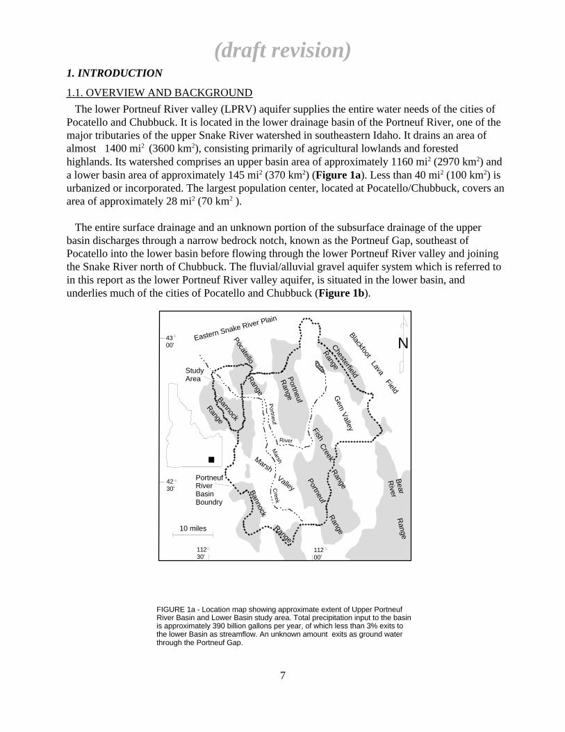
The lower Portneuf River valley (LPRV) aquifer supplies the entire water needs of the cities ofPocatello and Chubbuck. It is located in the lower drainage basin of the Portneuf River, one of themajor tributaries of the upper Snake River watershed in southeastern Idaho. It drains an area ofalmost 1400 mi2 (3600 km2), consisting primarily of agricultural lowlands and forestedhighlands. Its watershed comprises an upper basin area of approximately 1160 mi2 (2970 km2) anda lower basin area of approximately 145 mi2 (370 km2) (Figure 1a). Less than 40 mi2 (100 km2) isurbanized or incorporated. The largest population center, located at Pocatello/Chubbuck, covers anarea of approximately 28 mi2 (70 km2 ).
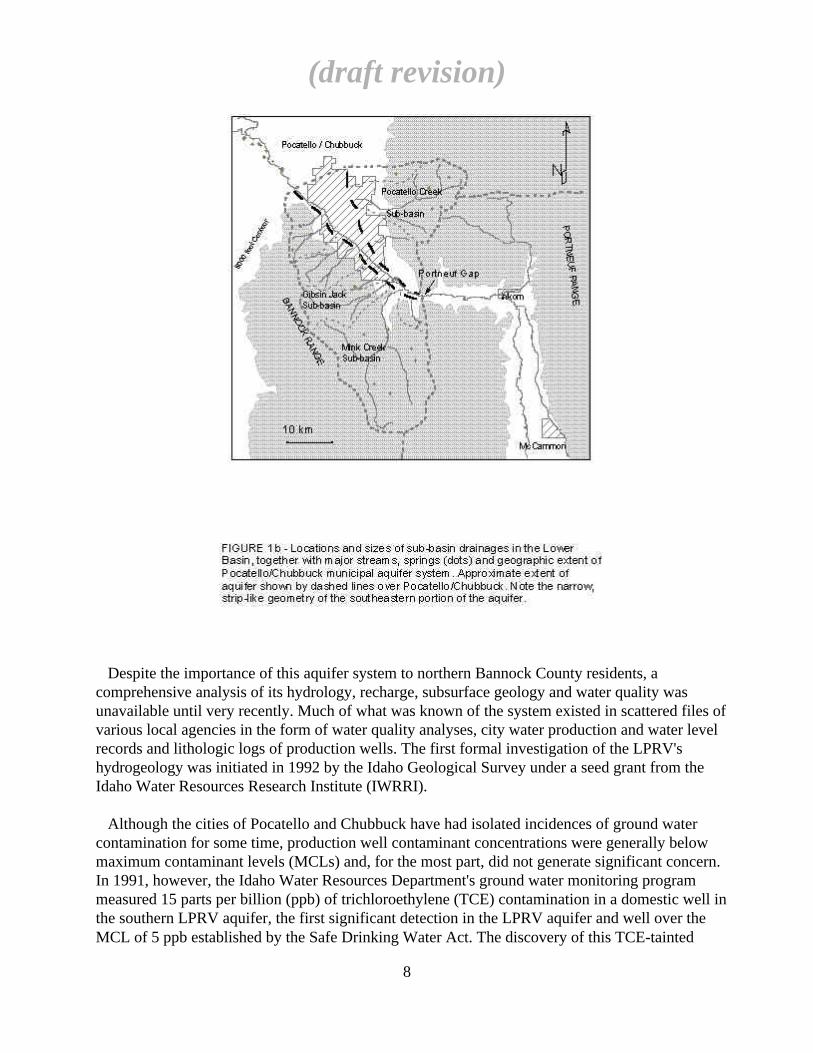
The entire surface drainage and an unknown portion of the subsurface drainage of the upperbasin discharges through a narrow bedrock notch, known as the Portneuf Gap, southeast ofPocatello into the lower basin before flowing through the lower Portneuf River valley and joiningthe Snake River north of Chubbuck. The fluvial/alluvial gravel aquifer system which is referred toin this report as the lower Portneuf River valley aquifer, is situated in the lower basin, andunderlies much of the cities of Pocatello and Chubbuck (Figure 1b).
(draft revision)
7
112 30'
43 00'
42 30'
112 00'
N
10 miles
Gem
Valley
Bear
River
Range
Eastern Snake River Plain
Chesterfield
Range
Portneuf
Range
Fish
Range
PortneufR
angeRange
Bannock
Bannock
Range
PocatelloR
ange
MarshValley
StudyArea
PortneufRiverBasinBoundry
Creek
BlackfootLava
Field
Portneuf
River
Marsh
Creek
FIGURE 1a - Location map showing approximate extent of Upper Portneuf River Basin and Lower Basin study area. Total precipitation input to the basin is approximately 390 billion gallons per year, of which less than 3% exits to the lower Basin as streamflow. An unknown amount exits as ground water through the Portneuf Gap.
Despite the importance of this aquifer system to northern Bannock County residents, acomprehensive analysis of its hydrology, recharge, subsurface geology and water quality wasunavailable until very recently. Much of what was known of the system existed in scattered files ofvarious local agencies in the form of water quality analyses, city water production and water levelrecords and lithologic logs of production wells. The first formal investigation of the LPRV'shydrogeology was initiated in 1992 by the Idaho Geological Survey under a seed grant from theIdaho Water Resources Research Institute (IWRRI).
Although the cities of Pocatello and Chubbuck have had isolated incidences of ground watercontamination for some time, production well contaminant concentrations were generally belowmaximum contaminant levels (MCLs) and, for the most part, did not generate significant concern.In 1991, however, the Idaho Water Resources Department's ground water monitoring programmeasured 15 parts per billion (ppb) of trichloroethylene (TCE) contamination in a domestic well inthe southern LPRV aquifer, the first significant detection in the LPRV aquifer and well over theMCL of 5 ppb established by the Safe Drinking Water Act. The discovery of this TCE-tainted
(draft revision)
8

ground water upgradient of the Pocatello municipal well field raised official concern over futurewell head protection strategy for the well field, and precipitated the move to establish a formalwell head protection (WHP) program with the aid of a grant from the Environmental ProtectionAgency. Through the efforts of the City's Community Development and Research department andthe Idaho Geological Survey (IGS), work was begun on characterizing the LPRV's geohydrologyand defining a WHP program. The timing of this work was fortunate for, in 1993, levels of TCE intwo upgradient production wells rose above the MCL, forcing their closure and threatening theentire municipal well field. At the same time that Pocatello was struggling with its upgradientcontaminant problems, the City of Chubbuck was confronting a serious perchloroethylene (PCE)contamination problem which forced closure action on three of its four production wells in thedowngradient portion of the aquifer system.
Both problems were regional in scope, and remediation efforts in both suffered from the lack ofa comprehensive geohydrologic model of the LPRV aquifer system. Through work initiated underfunding from IWRRI and the EPA, a preliminary conceptual model of the system was developedto help guide remediation efforts (Welhan and Meehan, 1994). Through a subsequent contract withthe City of Pocatello, this model has been refined with microgravity surveying and thedevelopment of an aquifer system-wide database for analyzing subsurface geology.
This report constitutes a summary of the current geohydrologic model of the system, asdeveloped jointly through work funded by the EPA WHP Grant, the IWRRI seed grant, and Cityof Pocatello contract (the latter augmented with a funded extension in 1995). In order to generatethe maximum benefit from related data, this report also draws on recent gravity survey dataobtained under a U.S. Geological Survey-sponsored mapping program. All of this work has hadthe common goal of understanding the physical geology, aqueous chemistry and hydrology of theLPRV aquifer system and of developing a comprehensive conceptual geohydrologic model.Because the objectives of the IWRRI seed grant, the EPA WHP Demonstration Grant and the Cityof Pocatello contract are so intimately connected, and because all were intended to incorporate thebest available information from all sources for the purposes of aquifer characterization, this reporthas been written as a summary of work performed under all three projects. A description ofmonitoring wells drilled under funding from IWRRI and EPA for this work is included inAppendix I. Data and preliminary results of the gravity survey work and a description of theaquifer-wide database are included in Appendices II and III, respectively. In addition, the reportdeals with the implications of the geohydrologic model for WHP capture zone modeling and thedefinition of WHP areas for the aquifer system.
1.2. FUNDING SOURCES
EPA funding provided for two-thirds of the monitoring well installation, water sampling andchemical analysis, well testing, and salary support for Idaho State University graduate geologystudent C. Meehan's M.S. thesis research. The IWRRI grant funded one-third of the wellinstallation costs, seismic refraction surveying, chemical analyses and partial student salarysupport. The City contract (plus a funded extension) provided funding for development of ageohydrologic database and system-wide conceptual model and supported Idaho State Universitygraduate geology student T. Reid's gravity survey work, which will constitute the major portion ofan M.S. Geology thesis.
(draft revision)
9
1.3. OBJECTIVES
Work on the LPRV aquifer system was begun in 1992 by the IGS and ISU in a study funded byIWRRI. The primary objective of that work was to assemble all available background data on theaquifer system and to perform a preliminary geohydrologic characterization.This funding waspartially responsible for the installation of the first monitoring wells in the LPRV aquifer and alsoled to the procurement of additional funding to expand on the scope of the initial work. The EPAWHP Demonstration Grant and the City of Pocatello contract were intended to extend and refinethe preliminary hydrogeologic characterization work begun under the IWRRI seed grant.
The objectives of the WHP Demonstration Project were two-fold: 1) to characterize the geologyand hydrology of the aquifer system and define WHP areas based on that data, and 2) to assess thetypes, nature and locations of potential contaminants on and near the municipal well field and thevulnerability of the aquifer to these potential ground water contaminants. The latter goal wasaddressed through a subcontract, with results summarized in a companion report (-Hill, 1994a).
The objectives of the City of Pocatello contract were also two-fold: 1) to conduct a detailedmicrogravity survey of the LPRV in order to provide additional subsurface control for theconceptual geologic model of the aquifer; and 2) to assemble all relevant suburface information ina system-wide database and, utilizing this information, to refine the existing geohydrologic modelof the LPRV and its aquifer system.
1.4. SCOPE
Figure 2 shows the area of study included in this report for the EPA WHP grant and the City ofPocatello contract, as well as areas covered by other major remediation and data generationactivities in the LPRV region. The LPRV aquifer system is comprised of two distinct subsystems:a deep, stratified northern aquifer system and a relatively shallow southern aquifer system, whosemutual boundary is defined by subsurface bedrock structure (Welhan and Meehan, 1994). Thedepth and geologic complexity of the northern aquifer system is poorly constrained by availablewell log data whereas the shallow southern aquifer is defined by numerous wells. An overview ofthe current state of knowledge of the northern aquifer system based on the well database ispresented in Section 3.2.1.
Because of the size, complexity and data paucity of the northern aquifer system, work under theEPA WHP project and the city-funded gravity survey was focused on the southern system so that asubsurface model of the southern aquifer could be developed and tested; such work in the northernsystem will not be possible until significantly more subsurface data become available. In addition,existing and future ground water contamination in the southern aquifer has the potential to threatenthe entire down-gradient well field, and so dictates a higher priority for subsurface characterizationwork in that area. Because of these considerations, the WHP Demonstration Project and thegravity survey portion of the City contract are focused on the southern aquifer system. In addition,the development and analysis of the comprehensive well database focused primarily on thesouthern system.
(draft revision)
10

Study area boundaries for the southern aquifer system were defined on the basis of hydrologicboundaries and on the immediate need to characterize the physical properties of the portion of thesystem from which originates. Water balance and recharge components of the study thereforefocus on the high-precipitation region of the LPRV watershed south of the aquifer and anassessment of the relative contribution from the upper Portneuf watershed.
(draft revision)
11

2. PREVIOUS WORK AND DATA SOURCES
2.1. PUBLICATIONS AND REPORTS
2.1.1. Geology
Previous geologic descriptions of the area have been published by Ludlum (1943), Trimble(1976), Scott (1982), Scott et al.. (1982), LaPoint (1977), Rember and Bennett (1979), Ore (1982),Link et al. (1985), Burgel et al. (1987) and Houser (1992). McDole (1969), McDole et al. (1973)and Jasmer (1987) described and mapped surficial loess deposits in the area. Several M.S. geologytheses have been done in and around the Pocatello area, including Muller (1978), LeFebre (1984)and Bush (1980). A wealth of unpublished bedrock and surficial geologic data have been madeavailable by Idaho State University's Geology Department (D. Rodgers, pers. comm., 1994). TheIdaho Geological Survey, in cooperation with Idaho State University, is nearing completion of adetailed 1:24000 map of surficial geology (including the Tertiary geology) of the Pocatello South7.5 minute quadrangle (Osier and Othberg, in prep.). Surface geologic information in this report isbased primarily on this mapping as well as on Trimble (1976) and unpublished maps at Idaho StateUniversity (D. Rodgers, unpubl. data). The basin's geologic history is based on an unpublishedsummary by Rodgers et al. (1994).
2.2.2. Hydrogeology
Hydrogeologic conditions in the northwestern portion of the basin have been described byMansfield (1920), Stearns et al. (1938), Crosthwaite (1957) and West and Kilburn (1963). Thosesources deal primarily with conditions in the Fort Hall Bottoms and Michaud Flats areas, as doeswork by Jacobsen (1982, 1984) and Goldstein (1981). Corbett et al. (1980) described thehydrogeology of the Tyhee area as it pertained to the geothermal resource potential of the area. Thehydrogeology of a portion of the Pocatello Creek tributary drainage has been described byCH2M-Hill (1994b), as has the nature of inorganic salt contamination in that drainage.Geotechnical reports on spilled fuel remediation are available for several areas in the northernaquifer, but all deal with shallow subsurface characterization. Welhan and Meehan (1994)published a preliminary interpretation of the northern aquifer system' s geohydrology. Recently,the City of Chubbuck drilled three deep exploratory test wells in the northern aquifer (CH2M-Hill,1994c).
Prior to this study, very little published hydrogeologic information existed on the aquifer beneaththe Pocatello-Chubbuck city limits or that portion southeast of Pocatello to the Portneuf Gap.Norvitch and Larson (1970) and Seitz and Norvitch (1979) had published reconnaissance data onthe hydrology and ground water chemistry, respectively, of the upper Portneuf River Valleydrainage basin which provided some background data on the LPRV system. Kindel et al. (1991)and Brown and Caldwell (1994) reported on hydrogeologic work in the mouth of Fort HallCanyon, a tributary valley aquifer at the south end of the valley. (Winter et al., 1994). The mostcomprehensive information on the hydrogeology of the southern aquifer is that of Welhan andMeehan (1994). Additional information on basin bedrock depth and subsurface boundaries derivedfrom modeling of gravity data is available in Reid et al. (1995; Appendix II-A) and recent,unpublished data of Reid (Appendix II-B, -C). Results of seismic refraction work in a portion ofthe aquifer was reported by Pelton et al. (1994).
(draft revision)
12

Information on aquifer hydrochemistry was published by Meehan and Welhan (1994). Winter etal. (1994) published a valuable summary of nitrate and salt-contaminated groundwater in theeastern part of the southern LPRV system. Work on the remediation of TCE contamination in thesouthern Pocatello well field has provided much new information on the hydrogeologiccharacteristics of a portion of the southern aquifer system (CH2M-Hill, 1994d; Figure 2), andwater quality surveys by the City of Pocatello (F. Ostler, pers. comm., 1995) have extended ourknowledge of TCE plume dynamics and hence the dynamics of flow and transport in the southernaquifer. An unpublished internal report by IDEQ (1995) summarizes all ground watercontamination problems in the LPRV.
2.2. SOURCES OF DATA
Meteorological data were obtained from the Department of Transportation's meteorologicalstation located at the Pocatello airport, approximately 6 miles west of the city. The US GeologicalSurvey has monitored ground water levels and water quality in selected domestic wells in theLPRV aquifer and maintains records of Portneuf River discharge which are published in annualstate water summaries (Harenberg et al., 1993). The state Department of Water Resourcesmaintains copies of domestic well logs filed by commercial drillers which, together with municipaland monitoring well logs, formed the basis of the system-wide database (Appendix III).
In addition to formal publications, this study has relied on a large amount of previouslyuncollated data on subsurface lithology, water level conditions and water quality that has beenassembled from records of the City of Pocatello's Water Department, the City of Chubbuck'sPublic Works Department, the IDWR, and the Idaho Division of Environmental Quality.
2.3. WORK IN PROGRESS
Several projects are currently in progress which will provide additional valuable information forsystem characterization. Surficial geologic mapping of the Pocatello North quadrangle is beingconducted by the IGS in collaboration with ISU under funding from the U.S. Geological Survey'sUrban Mapping Program. As part of this work, gravity surveying in the northern aquifer isintended to help define depth to bedrock, and an updated surface bedrock geologic map is alsoexpected to be produced as part of the IGS-ISU collaboration. Several ISU M.S. thesis researchprojects on aquifer chemistry and chemical mass balances, gravity modeling of subsurface basinlithology, the hydrogeology of the Mink Creek corridor, and the recharge characteristics and alpinebasin hydrology of the Mink Creek watershed are either in progress or have been recentlycompleted.
(draft revision)
13
3. GEOLOGY
3.1. REGIONAL GEOLOGY
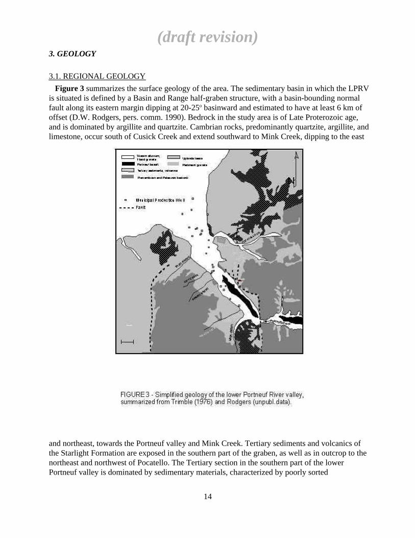
Figure 3 summarizes the surface geology of the area. The sedimentary basin in which the LPRVis situated is defined by a Basin and Range half-graben structure, with a basin-bounding normalfault along its eastern margin dipping at 20-25o basinward and estimated to have at least 6 km ofoffset (D.W. Rodgers, pers. comm. 1990). Bedrock in the study area is of Late Proterozoic age,and is dominated by argillite and quartzite. Cambrian rocks, predominantly quartzite, argillite, andlimestone, occur south of Cusick Creek and extend southward to Mink Creek, dipping to the east
and northeast, towards the Portneuf valley and Mink Creek. Tertiary sediments and volcanics ofthe Starlight Formation are exposed in the southern part of the graben, as well as in outcrop to thenortheast and northwest of Pocatello. The Tertiary section in the southern part of the lowerPortneuf valley is dominated by sedimentary materials, characterized by poorly sorted
(draft revision)
14

conglomerates, alluvial and colluvial bouldery gravel and sedimentary breccia (Trimble, 1976;Ore, 1982).
The Quaternary/Holocene geology of the lower Portneuf river valley is dominated by fluvial andalluvial gravels which occur over the valley floor which, in most areas, is blanketed by 5 to 20 feetof silt and loess. Along the eastern side of the southern part of the valley, two superimposed basaltflows form a 50 foot-high tableland on the eastern side of the valley which overlooks the floor ofthe western half of the valley. This basalt, known as the basalt of Portneuf Valley (or PortneufBasalt, in this report), is of Pleistocene age (583,000 yrs BP, G.B. Dalrymple in Scott et al., 1982)and flowed into the lower Portneuf valley from vents in Gem Valley, 40 miles southeast, throughthe Portneuf Gap. As such, it predates the gravels and silts exposed on the floor of the western sideof the valley which it overlooks.
The gravels on the valley floor northwest of City Creek are predominantly of fluvial andBonneville flood origin. Gravel in this area was deposited 14,500 years BP and is known as theMichaud Gravel (Trimble, 1976). This unit fans out into the Snake River Plain and comprises a40-60 foot thick layer of coarse gravel overlying the American Falls Lake clay unit (72 ± 14 kyrBP). The Michaud gravels are believed to have been deposited by the flood from pluvial LakeBonneville as it debouched onto the Snake River Plain approximately 14,500 yrs BP (Scott et al.,1982; O'Conner, 1993). This event was responsible for scouring the surface of the Portneuf Basaltand the pre-existing valley fill along the western margin of the basalt and depositing extensivewell-sorted, coarse gravels and sands along the lower Portneuf River valley. It is uncertain whetherthe coarse upper gravels of the southern aquifer southeast of City Creek are contemporaneous withthe Michaud unit. At least part of the southern aquifer's gravels, which are covered by acontinuous mantle of post-Bonneville Flood river silt and loess of variable thickness, weredeposited during or shortly after the Bonneville Flood, but unknown portions of this lithologicassemblage may pre- and post-date the flood.
3.2. AQUIFER GEOLOGY
3.2.1. Descriptive Cross-Sections
Figure 4 shows the extents of the geographic areas used to subdivide the aquifer system and thelocations of wells and cross-sections used to constrain subsurface geology. The geographicsubdivision is partly arbitrary, reflecting a coarse categorization based on subsurface geology. Thenorthern aquifer system comprises multiple, confined silty gravel and sand aquifers hosted instratified sedimentary basin fill at least 500 feet thick; the central area is defines by a thinsedimentary portion overlying shallow bedrock; the southern aquifer system is characterized byvery permeable, unconfined gravels overlying a much thicker section of low-permeability basin fillsediments; and the relatively small, unconfined eastern aquifer is comprised of silty gravels of lowpermeability.
(draft revision)
15

Geologic cross sections are shown in Figures 5, 6 and 7; Section E-E' was constructed in thelocation of the most recent test well drilling that was conducted during TCE remediation work(CH2M-Hill, 1994c).
Figure 5 represents a synthesis of subsurface geology along transect A-A', from northwest tosoutheast, based on key units. The lack of any borehole geophysical correlative control at this stagemakes this interpretation necessarily tentative, particularly in the northern aquifer system.However, in creating the geologic interpretation of Figure 5, only those units that were consideredto be consistently identifiable by a conscientious driller (namely: thick clay beds; basalt and basaltrubble units; and crystalline bedrock) were used for correlation purposes. In addition to the fewmodestly deep boreholes constraining minimum thicknesses of basin fill in the northern andsouthern aquifers, gravity data has provided clear evidence of at least 2500 feet of sedimentthickness in the southern aquifer and over 4000 feet in the northern aquifer, separated by a bedrockhigh that is within 150 feet of the surface.
Perhaps the most striking feature of Figure 5 is the presence of the bedrock high which separatesthe aquifer into southern and northern portions. Henceforth, these portions of the aquifer systemwill be referred to as the southern and the northern aquifers. The bedrock high may be a
(draft revision)
16
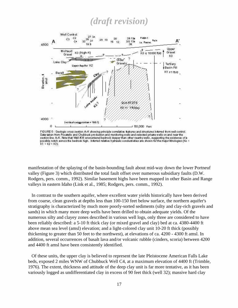
manifestation of the splaying of the basin-bounding fault about mid-way down the lower Portneufvalley (Figure 3) which distributed the total fault offset over numerous subsidiary faults (D.W.Rodgers, pers. comm., 1992). Similar basement highs have been mapped in other Basin and Rangevalleys in eastern Idaho (Link et al., 1985; Rodgers, pers. comm., 1992).
In contrast to the southern aquifer, where excellent water yields historically have been derivedfrom coarse, clean gravels at depths less than 100-150 feet below surface, the northern aquifer'sstratigraphy is characterized by much more poorly-sorted sediments (silty and clay-rich gravels andsands) in which many more deep wells have been drilled to obtain adequate yields. Of thenumerous silty and clayey zones described in various well logs, only three are considered to havebeen reliably described: a 5-10 ft thick clay (or mixed gravel and clay) bed at ca. 4380-4400 ftabove mean sea level (amsl) elevation; and a light-colored clay unit 10-20 ft thick (possiblythickening to greater than 50 feet to the northwest), at elevations of ca. 4200 - 4300 ft amsl. Inaddition, several occurrences of basalt lava and/or volcanic rubble (cinders, scoria) between 4200and 4400 ft amsl have been consistently identified.
Of these units, the upper clay is believed to represent the late Pleistocene American Falls Lakebeds, exposed 2 miles WNW of Chubbuck Well C4, at a maximum elevation of 4400 ft (Trimble,1976). The extent, thickness and attitude of the deep clay unit is far more tentative, as it has beenvariously logged as undifferentiated clay in excess of 90 feet thick (well 32); massive hard clay
(draft revision)
17
intercalated over 50 feet with thin gravel seams (well 26); sticky clay (wells C4, 27, 29); stickyyellow clay and sandy yellow clay (wells 18, 34); and sticky brown clay (well 31). It is shown inFigure 5 with a fairly uniform thickness, dipping at ca. 4o. Based on Chubbuck Wells C2 and C4,this clay unit may thicken northward, although the quality of the lithologic log information in deepwell C4 is suspect; results of recent test well drilling in the vicinity of Chubbuck Well C2(CH2M-Hill, 1995b) indicate that this clay unit is fairly thin and within 50 feet of the base of thebasalt flows. This unit cannot be identified with any certainty in well 10 (although it may bepresent) since this well was logged as a series of sandy clays from 4300 ft down to 4113 ft amsl.
Correlations between the basalt occurrences identified in these wells has not been attempted.Discontinuous basalt flows intercalated with sediments are a characteristic feature of thesubsurface lithology in the Snake River Plain (Corbett et al., 1980; Houser, 1992). It is not knownwhether the basalt logged in wells 16 and 30 is correlative with the basalt occurrences identified inChubbuck wells to the north or even whether these scattered occurences high in the sectionrepresent basalt boulders rather than flow remnants.
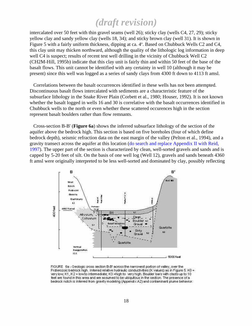
Cross-section B-B' (Figure 6a) shows the inferred subsurface lithology of the section of theaquifer above the bedrock high. This section is based on five boreholes (four of which definebedrock depth), seismic refraction data on the east margin of the valley (Pelton et al., 1994), and agravity transect across the aquifer at this location (do search and replace Appendix II with Reid,1997). The upper part of the section is characterized by clean, well-sorted gravels and sands and iscapped by 5-20 feet of silt. On the basis of one well log (Well 12), gravels and sands beneath 4360ft amsl were originally interpreted to be less well-sorted and dominated by clay, possibly reflecting
(draft revision)
18
a separate stratigraphic unit. However, recent indirect evidence from micro-gravity profiling of thebedrock along section B-B' and movement of the TCE contaminant plume away from the westargin of the Upper Gravel aquifer through the center of the valley at the location of Wells 12 and16, suggests that a 60-80 ft deep notch in the bedrock sill exists almost exactly half-way betweenWells 30a and 12 along section B-B'. Although the existence of such a notch has not beenconfirmed by gravity surveying for logistical reasons (this portion of the valley is underlain by thecentral rail yard of Union Pacific Railroad), its inferred depth and location are consistent with thebedrock configuration discussed below in Figure 6b.
Unlike the eastern margin of this section, which is defined by what appears to be a planar(possibly fault-controlled) bedrock scarp of dense, massive Proterozoic quartzite (Caddy Canyon),the western margin's bedrock limits are unknown at this location. Although inferred Caddy Canyonquartzite outcrops along the western valley margin immediately south of section B-B', the lateralextent, composition or thickness of the sedimentary section west of well 7 is not known, althoughthe permeability of these materials is very probably low compared with that of the Upper Gravel sothat the west margin of the Upper Gravel aquifer is considered well-defined in a hydraulic sense.
Sediments encountered in four wells clustered around well 7 are dominated by clay, silt andboulders, and are interpreted to represent fanglomerate derived from City Creek drainage. Basedon well 7's specific capacity, the alluvial fan sediments appear to be one tenth to one hundreth aspermeable as the clean gravels in the upper part of the section in the southern aquifer (seediscussion of hydraulic data in a later section). The cross-sectional area available for ground waterunderflow through the portion of B-B' within the saturated gravels above the basalt is 2.0 x 105 ft2.If the gravels below the basalt are included, the total potential cross-sectional area of flow is ca.3.5 x 105 ft2. The inferred bedrock notch would add an additional 0.2 x 105 ft2 of saturatedcross-sectional area, for a total of about 3.7 x 105 ft2.
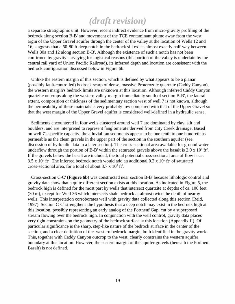
Cross-section C-C' (Figure 6b) was constructed near section B-B' because lithologic control andgravity data show that a quite different section exists at this location. As indicated in Figure 5, thebedrock high is defined for the most part by wells that intersect quartzite at depths of ca. 100 feet(30 m), except for Well 36 which intersects shale bedrock at almost twice the depth of nearbywells. This interpretation corroborates well with gravity data collected along this section (Reid,1997). Section C-C' strengthens the hypothesis that a deep notch may exist in the bedrock high atthis location, possibly representing an early analog of the Portneuf Gap, cut by a superposedstream flowing over the bedrock high. In conjunction with the well control, gravity data placesvery tight constraints on the geometry of the bedrock surface at this location (Appendix II). Ofparticular significance is the sharp, step-like nature of the bedrock surface in the center of thesection, and a clear definition of the western bedrock margin, both identified in the gravity work .This, together with Caddy Canyon outcrop to the west, clearly constrains the western aquiferboundary at this location. However, the eastern margin of the aquifer gravels (beneath the PortneufBasalt) is not defined.
(draft revision)
19
Unlike Section B-B', there is no indication of poorly sorted gravels overlying bedrock in thevicinity of either Well 36 or Well 3, although a thick (40 ft) section of brown clay underlies theUpper Gravel at Well 36. The entire gravel section, although smaller in area than that at B-B' (2.5x 105 ft2), is apparently uniformly coarse-grained and well-sorted. The hydraulic conductivity of these wells also is extremely high (Section 4.1.3), indicating that sediment sorting is enhanced,possibly because of the narrow, notch-like aspect of the paleovalley at this point.
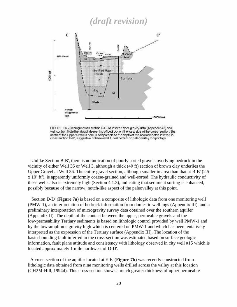
Section D-D' (Figure 7a) is based on a composite of lithologic data from one monitoring well(PMW-1), an interpretation of bedrock information from domestic well logs (Appendix III), and apreliminary interpretation of microgravity survey data obtained over the southern aquifer(Appendix II). The depth of the contact between the upper, permeable gravels and thelow-permeability Tertiary sediments is based on lithologic control provided by well PMW-1 andby the low-amplitude gravity high which is centered on PMW-1 and which has been tentativelyinterpreted as the expression of the Tertiary surface (Appendix III). The location of thebasin-bounding fault inferred in the cross-section was estimated based on surface geologicinformation, fault plane attitude and consistency with lithology observed in city well #15 which islocated approximately 1 mile northwest of D-D'.
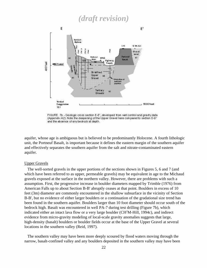
A cross-section of the aquifer located at E-E' (Figure 7b) was recently constructed fromlithologic data obtained from nine monitoring wells drilled across the valley at this location(CH2M-Hill, 1994d). This cross-section shows a much greater thickness of upper permeable
(draft revision)
20
gravels than was encountered at D-D'. However, at both locations, the permeable upper gravelsappear to be bounded along their base and western margin by cemented Tertiary gravels.
The Portneuf basalt is shown in cross-sections C-C', D-D' and E-E' as resting on a sedimentarysection. These sediments are interpreted to represent valley fill that predates the Bonneville floodand, hence, the upper permeable gravels. Municipal well #15 provides the only reliable data onsubsurface lithology east of the basalt, although a number of domestic well logs in the vicinity ofD-D' and E-E' east of the basalt indicate either the absence of bedrock or indurated Tertiarymaterial at shallow depth or their presence at greater depth (Appendix III). It is proposed that, eastof the basalt, a shallow alluvial aquifer of relatively poorly sorted bouldery gravel and silty sandoverlies Tertiary sediments of unknown thickness which, in turn, overlie shale bedrock.
3.2.2. Lithologic Units
On the basis of sharply contrasting lithologic and hydraulic properties, three lithologic groupsare defined in the southern aquifer: 1) bedrock, of variable composition, but dominated by pink towhite quartzite and varicolored shale or argillite, predominantly of Proterozoic age; 2) Middle toLate Tertiary basin-filling sediments and volcaniclastics of the Salt Lake Group, widely induratedto varying degree, and unindurated silty gravels of Pleistocene age; and 3) coarse, clean gravel inthe uppermost part of the valley section, which constitutes the most important host for the southern
(draft revision)
21
aquifer, whose age is ambiguous but is believed to be predominantly Holocene. A fourth lithologicunit, the Portneuf Basalt, is important because it defines the eastern margin of the southern aquiferand effectively separates the southern aquifer from the salt and nitrate-contaminated easternaquifer.
Upper Gravels
The well-sorted gravels in the upper portions of the sections shown in Figures 5, 6 and 7 (andwhich have been referred to as upper, permeable gravels) may be equivalent in age to the Michaudgravels exposed at the surface in the northern valley. However, there are problems with such aassumption. First, the progressive increase in boulder diameters mapped by Trimble (1976) fromAmerican Falls up to about Section B-B' abruptly ceases at that point. Boulders in excess of 10feet (3m) diameter are commonly encountered in the shallow subsurface in the vicinity of SectionB-B', but no evidence of either larger boulders or a continuation of the gradational size trend hasbeen found in the southern aquifer. Boulders larger than 10 foot diameter should occur south of thebedrock high. Basalt was encountered in well PA-7 during test drilling (Figure 7b), whichindicated either an intact lava flow or a very large boulder (CH2M-Hill, 1994c), and indirectevidence from micro-gravity modeling of local-scale gravity anomalies suggests that large,high-density (basalt) boulders or boulder fields occur at the base of the Upper Gravel at severallocations in the southern valley (Reid, 1997).
The southern valley may have been more deeply scoured by flood waters moving through thenarrow, basalt-confined valley and any boulders deposited in the southern valley may have been
(draft revision)
22
subsequently buried in the waning flood stage or by fluvial depositional processes in the post-floodperiod. This suggestion is supported by modeling of gravity data which suggests that basalt occursat the base of the Upper Gravels in four of six cross-valley gravity transects (Reid, 1997).
Secondly, although test well drilling with dual-wall air percussion methods conducted byCH2M-Hill near the west end of Section E-E' did not reveal evidence of sandy lenses within thegravel package, air rotary drilling at PMW-2 and recent test holes drilled by the City of Pocatellonear the east end of Section E-E' produced clear indications of sandy lenses intermingled with theupper gravel (see monitoring well logs, Appendix I). Significant sand accumulations were alsoencountered during gravel excavation at the Highway Pond borrow pits (B. Brown, pers. comm.,1996), and have also been observed in recent excavations in the uppermost cross-bedded gravelsexposed in the borrow pits, which also contain ostracod shells. In the city test holes, sand lensesshallower than than about 20 feet also contain ostracod shells; at this location the Upper Gravelwas found to thin to less than 40 feet as far as 300 feet west of the Portneuf Basalt. This evidencesuggests that flood gravels have been partially reworked by late-stage and post-flood fluvialprocesses. Finally, the hydraulic response of the upper gravel unit to pumping indicates thatvertical hydraulic conductivity is significantly lower than the horizontal hydraulic conductivity(Section 4.2.2) and that significant permeability anisotropy also exists in the horizontal plane(CH2M-Hill, 1994d), both suggestive of facies development. These characteristics would beexpected in a package of braided stream gravels, but are difficult to reconcile with the chaoticdistribution of particle sizes expected during a single depositional event from coarse bedload in therecessional flood stage, as seen in the bouldery Michaud Gravel where it is exposed in the northernaquifer. This may indicate either that flood deposition occurred gradually rather than as a singlebrief event, or that some portion of the flood gravels were later reworked in a high-energyenvironment, possibly in the late flood stage or in the post-flood period.
For this reason, the permeable gravels that comprise the bulk of the southern aquifer are describedhere as the Upper Gravel unit, so as not to connote any genetic or age relationship with theBonneville flood-derived Michaud gravel to the north.
Tertiary Basin Fill and Transitional Units
At an elevation ranging from about 4340 ft amsl in well #12 (Section B-B'; Figure 6a) to about4325 ft amsl in monitoring well PA-7 (Section E-E'; Figure 7b), the Upper Gravels appear totransition abruptly into a much more silt- and clay-rich gravel unit. These sediments which mayrepresent either Tertiary or Pleistocene material. An intact Tertiary section in the subsurface is bestdescribed in monitoring well PMW-1 where the base of the Upper Gravel occurs at a much higherelevation of about 4395 ft amsl (Section D-D'; Figure 7a). At this location the Upper Gravel restsdirectly on a series of partially indurated sands, silty sands and intercalated clays, including a thin,grey volcanic ash and a dense, white clay overlying very hard, cemented gravel that islithologically indistinguishable from the cemented Starlight Formation outcropping on BannockHighway at Gibson Jack Creek.
A simple structure contour interpretation, based on the average dip of the basin-bounding faulton the north side of the graben and the average stratigraphic dip of the Paleozoic bedrock units onthe south side, suggests that the Tertiary sedimentary section in the southern aquifer may be as
(draft revision)
23

thick as 3000-4000 feet (D.W. Rodgers, pers. comm., 1993). Reid (1997) modeled several gravitytransects in the southern valley and showed dramatic deepening of the bedrock basement southeastof Red Hill (Appendix II). The fact that well drillers have consistently encountered difficultdrilling conditions throughout the LPRV (and have consistently described this lithology asbedrock-like in domestic well logs) at depths that correlate with cemented Tertiary sedimentsencountered in monitoring wells, supports the contention that partly indurated Tertiary sedimentsoccur throughout the LPRV at depths below 100 - 200 feet (Appendix III).
Modeling of gravity data from the southern aquifer indicates that depth to bedrock (modeleddensity = 2.6 g/cm3) is at least 2500 feet, with indurated Tertiary sediments (model density = 2.35g/cm3) filling the structural trough beneath the Upper Gravel section. Tertiary sediments exposedin outcrop are of intermediate density (ie. partly indurated). Reid's (1997) modeling of gravityprofiles transverse to the valley axis define a paleovalley into which the Upper Gravel unit wasdeposited.
Cemented gravels have been identified in numerous wells in the southern aquifer; but rather thanconstituting a single, correlative unit, there appear to be multiple indurated zones in the TertiaryStarlight Formation (CH2M-Hill, 1994d). A hard clay or hardpan layer identified in severaldomestic wells in the vicinity of Well 13 and in production Well 14 (near PMW-1) may be amanifestation of this.
An effective regional base of the Upper Gravel/top of the intact Tertiary section can now bedefined on the basis of the depth of occurrence of materials that are significantly harder to drill.From an analysis of the lithologic database (Appendix III) and comparison of known bedrockdepths with what commercial water well drillers in the area have recorded as "bedrock" (under avariety of colorful descriptions!), it appears that difficult drilling conditions commonlyencountered in the southern valley are due to the occurrence of indurated Tertiary sediments, ratherthan bedrock. On the assumption that these materials are as indurated as those outcropping alongBannock Highway immediately south of Gibson Jack Creek, their hydraulic conductivity should bequite low. An analysis of well development data from the deep Forsman/Pein well indicates thatthe bulk hydraulic conductivity of the 80-390 ft open interval (ie. that part of the section that ispredominantly beneath the Upper Gravels) is several orders of magnitude lower than that of theupper gravel (Figure 5).
On the basis of the observed contrasts in lithology, bulk density and hydraulic conductivity,therefore, the effective base of the southern aquifer is provisionally defined as the top of theTertiary section. Because the top of the Tertiary section appears to vary considerably in elevation,it is also proposed that the thickness of the Upper Gravel aquifer varies considerably, and possiblynonuniformly, over the length of the southern valley. Assuming that the lateral boundaries of thesouthern aquifer are defined on the west side by low permeability bedrock and indurated Tertiarysediments and to the east by clay-rich Tertiary sediments beneath the Portneuf basalt (cf. Figure7a,b), the area available for ground water flow through the saturated Upper Gravel could varywidely from 4.5 x 105 ft2 (Section E-E'; Figure 7b) to 2.5 x 105 ft2 (Section C-C'; Figure 6b).(Check Q calc'n)
(draft revision)
24

Bedrock
No direct measurements of the hydraulic conductivity of bedrock are available to constrain itspermeability. Of 202 wells in the database (Appendix III), a number have specific capacityinformation for what appears to be "bedrock" completions. However, only three wells have openintervals deeper than reported "bedrock" depth, and all three of these were completed in whatappears to be Tertiary indurated rocks. It can only be surmised that wells that are terminated, andperforated, in bedrock have such low yields that development tests were not attempted.
Based on outcrop exposures, the permeability of bedrock is assumed to be entirely due tofractures. A zone of fracturing was encountered in the uppermost 5 feet of the Caddy Canyonquartzite during the drilling of PMW-3 (Appendix I). The fractures were filled with white clay sothat the rock mass likely has low permeability. If this is typical of fracture permeability throughoutthe area, then the hydraulic conductivity of bedrock can be assumed to be very low. A roughestimate of the bulk hydraulic conductivity of rocks on the western margin of the southern aquifer- many of which are fractured bedrock - is made at the end of Section 6, on the basis of themagnitude of the regional hydraulic gradient over the western aquifer margin (Appendix III; FigureA3.4) and the calculated annual inflow from the Bannock Range. The estimated value is 1 ft/day,which is in the mid-range of typical values for fractured rock (Freeze and Cherry, 1979), butappears to be of the same order of magnitude as indurated Tertiary sediments.
Portneuf Basalt Based on radiocarbon dating of buried wood, the basalt of Portneuf Valley is believed to havefilled the ancestral Portneuf River's channel at about 583,000 yr BP (T. Ore, pers. comm., 1995).This lava flow, which extends from the southern LPRV to its source in the Gem Valley, comprisesat least three layered flow units in northern Marsh Valley and two identifiable units in the southernLPRV. Its western margin was eroded during the Bonneville Flood. Although its original width isunknown, it may not have extended much farther west than its present position. Some evidence ofits original western margin is preserved at the base of an outcrop on Hildreth Road just north of theHighway Pond borrow pit. Over most of its outcrop in the LPRV, less than 100 feet of section isexposed, although in the northern Marsh Valley, its thickness is considerably greater. Its totalthickness in the LPRV was unknown until microgravity data became available recently. A gravityprofile across the basalt (Appendix II; Reid, 1997) indicates that the lava flow is no more than50-70 feet thick near its northern terminus, indicating that its base does not extend to anysignificant depth beneath the level of the present valley floor.
3.2.3. Late Cenozoic Valley Evolution
In order to synthesize the subsurface information currently available, a geologic history of thesouthern valley is proposed in Figure 8. This Late Cenozoic historical interpretation is drawnpartially from Rodgers et al. (1994) and H.T. Ore (pers. comm., 1994) and attempts to refine andreconcile existing geologic conceptual models with the observations and information obtained inthis study. It incorporates new information, including lithologic logs, outcrop information, wellhydraulic response, and micro-gravity profiling and modeling of the Upper Gravel.
(draft revision)
25

Deposition of the Upper Gravel during late Pleistocene-Holocene time may have occurred undertwo possible scenarios. In Scenario A (Figures 8a), a wholly stratified Upper Gravel unit wascreated in a paleovalley that was incised in pre-Bonneville time and filled with fluvial (and/orolder glacial flood) deposits. During the Bonneville flood, this unit was only partially scoured. Theportion of the section that was removed was subsequently refilled by more stratified fluvialdeposits. In this scenario, tributary alluvial fans aggraded into the valley throughout the pre- andpost-flood period (such as the poorly-sorted, bouldery gravels encountered in wells near the mouthof City Creek; Figure 6a). Part of the Upper Gravel unit would therefore predate the MichaudGravels, but the entire thickness of the Upper Gravels would be characterized by vertically-stratified, heterogeneous fluvial channel and bar facies.
Alternatively, in Scenario B (Figure 8b) the Bonneville flood scoured the sediments of thepaleovalley quite deeply and deposited a single, homogeneous basal gravel over which subsequenthigh-energy, fluvially-dominated sedimentation would have completed the formation of the UpperGravel. Under this scenario, some portion of the Upper Gravel, probably the earlier stage ratherthan the later, would be correlative with the extensive Michaud Gravel unit that fans out north ofRed Hill. At peak flood stage some tributary alluvial fans (such as the City Creek fan), their toeseroded away by flood waters, might have slumped or flowed into the main valley; similar, flood-induced destabilization of the western wall of the valley may have been responsible for thegeomorphology of the Johnny Creek area, which has been mapped as a massive slump feature(Othberg and Rodgers, 2000).
(draft revision)
26

Following the peak flood stage, tributary fans would have aggraded onto and interfingered withthe fluvially-deposited portion of the Upper Gravel (as seen at Fort Hall Canyon, where wells onthe lower quarter of the alluvial fan actually penetrate the fan deposits and are completed in theUpper Gravel; Brown and Caldwell, 199x). In either scenario, post-flood fluvial processes wereresponsible for the overbank deposits of fine, ostracod-rich silt that caps the Upper Gravel in thesouthern valley.
Scenario 8A seems incompatible with the magnitude of flood energy that was responsible fordeposition of the huge boulders found in the Michaud Gravels. To expect that most of thepre-existing southern valley fill would resist scouring when 10-foot diameter boulders weretransported over them seems implausible. Large basalt boulders and boulder bars encountered infoundation and street excavations from West Halliday to at least Carson Street, in drill holes at thebase of the Upper Gravel, and also inferred from micro-gravity modeling (Reid, 1997; AppendixA2, Figure A2.5b) must have been deposited in the early, peak-flood stage of Upper Gravelformation.
In Scenario 8B, flood scouring must have removed extensive amounts of pre-existing valley fill,including sediment and rock, consistent with the inferred power of the flood (O'Conner, 1996). Anevent of this magnitude also could have induced large-scale erosion-induced slumping and little ofthe valley's pre-flood morphology would have remained intact.
The principal criterion for deciding among these competing scenarios hinges on whether theUpper Gravel is primarily stratified or homogeneous. As discussed in Section 4.2.2, pumping testresults from Well 36 suggest that at least portions of this aquifer may behave in a semi-confined
(draft revision)
27
manner, possibly as a result of vertical stratification. Although grain size stratification and lensesof coarse sand were observed in the gravels at PMW-2 from 45 to approximately 100 feet(Appendix I), stratified material could have been deposited during the flood's recessional stage orduring a post-flood fluvial stage.
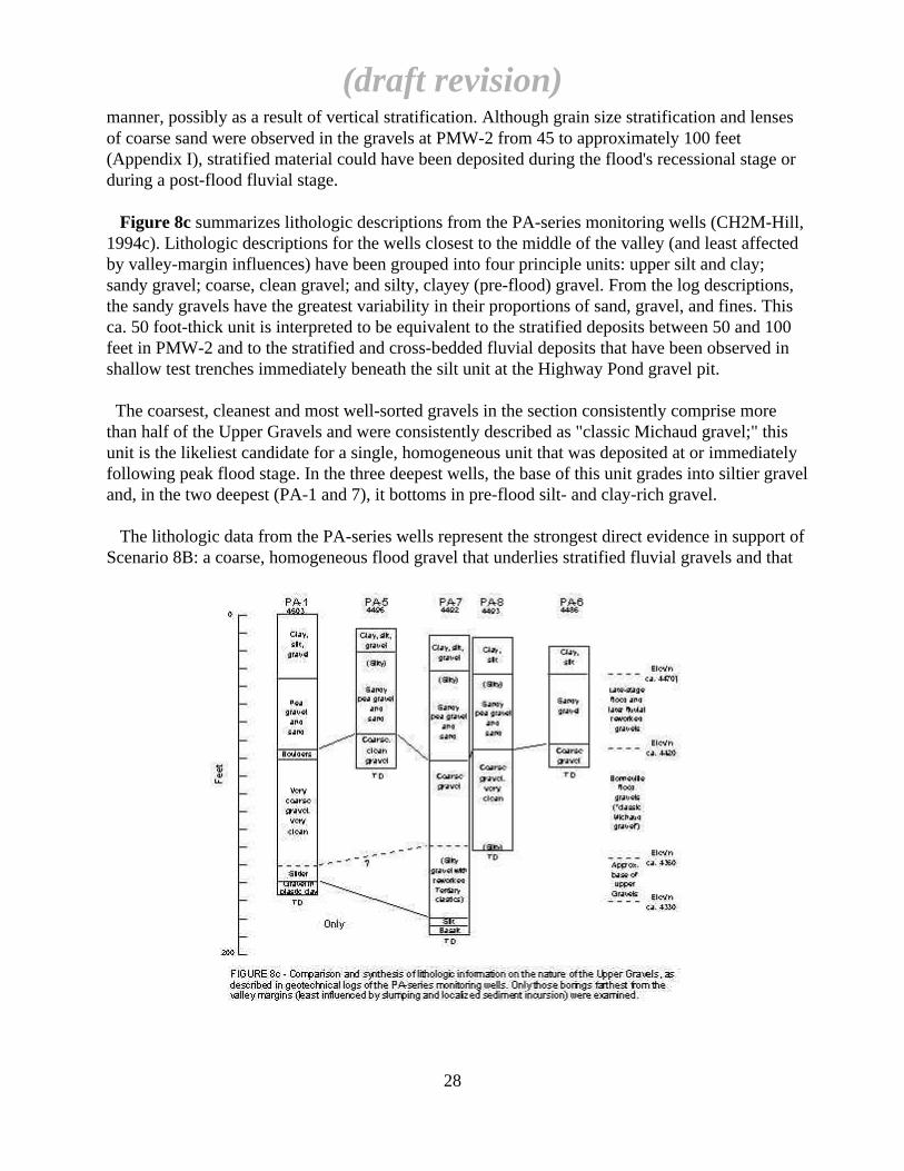
Figure 8c summarizes lithologic descriptions from the PA-series monitoring wells (CH2M-Hill,1994c). Lithologic descriptions for the wells closest to the middle of the valley (and least affectedby valley-margin influences) have been grouped into four principle units: upper silt and clay;sandy gravel; coarse, clean gravel; and silty, clayey (pre-flood) gravel. From the log descriptions,the sandy gravels have the greatest variability in their proportions of sand, gravel, and fines. Thisca. 50 foot-thick unit is interpreted to be equivalent to the stratified deposits between 50 and 100feet in PMW-2 and to the stratified and cross-bedded fluvial deposits that have been observed inshallow test trenches immediately beneath the silt unit at the Highway Pond gravel pit.
The coarsest, cleanest and most well-sorted gravels in the section consistently comprise morethan half of the Upper Gravels and were consistently described as "classic Michaud gravel;" thisunit is the likeliest candidate for a single, homogeneous unit that was deposited at or immediatelyfollowing peak flood stage. In the three deepest wells, the base of this unit grades into siltier graveland, in the two deepest (PA-1 and 7), it bottoms in pre-flood silt- and clay-rich gravel.
The lithologic data from the PA-series wells represent the strongest direct evidence in support ofScenario 8B: a coarse, homogeneous flood gravel that underlies stratified fluvial gravels and that
(draft revision)
28
comprises more than half of the Upper Gravel section. Thus, the Upper Gravel aquifer of thesouthern valley could be described as a composite unit representing both flood and post-flooddepositional processes.
The above interpretation may also explain the puzzling discontinuity in grain size distributionthat is observed in the Red Hill cross section (B-B'; Figure 6b). As shown in Figure 6b, grain sizesranging from clay and silt (in the "Dirty Gravel" unit) up to 10-foot and larger boulders andboulder bars occur from the vicinity of this cross-section northward for at least fifteen city blocks.The initial sediments deposited in this area during peak flood stage may have been less well-sortedthan elsewhere in the valley due to the bedrock flow obstruction. At peak flood stage, atremendous hydraulic jump would have existed across the bedrock lip as flood waters tumbled upand over it. At the same time that a thick bed load of coarse, well-sorted gravels was aggrading onthe upstream side of the bedrock lip, a melange of boulders and finer material was dropping out ofsuspension at the point of the hydraulic jump and its low-pressure zone. This process continueduntil upstream gravel deposition eliminated the hydraulic jump, at which point the erosive powerof the flood waters was in decline and the transition between peak-stage flood gravel deposition tolate-stage, high-energy fluvial deposition and reworking began. The upper portion of the poorlysorted assemblage that had been deposited was subsequently reworked in the fluvial stage, leadingto the sequence of clean, well-sorted bouldery gravels seen in the upper part of the section. Thishypothesis is testable because the clean gravels in the upper part of the Red Hill cross section arepredicted to be stratified and fluvially sorted but with the same volumetric proportion of proportion of larger clasts as the dirty gravels deeper in the section.
(draft revision)
29
4. HYDROLOGY
4.1. REGIONAL HYDROLOGY
The LPRV is located at the distal end of a large watershed (the upper Portneuf River basin),which receives an average of 52 x 109 ft3/yr of precipitation (Norvitch and Larson, 1970), whosesurface and subsurface discharge is focused through a narrow bedrock notch (the Portneuf Gap)into the LPRV. Discharge from the upper basin, together with recharge derived locally from the ca.145 mi2 lower basin, represents the only known sources of recharge for the LPRV.
Based on patterns of snowpack density and relative tributary valley catchment areas (Figure 1b),the principal sources of local recharge to the LPRV are believed to be (from southeast tonorthwest): underflow from Marsh Valley through the Portneuf Gap, Portneuf River seepagelosses, Mink Creek/Gibson Jack underflow, and Pocatello Creek underflow. In addition, lateralground water inflow to the valley through the pediment gravels along the southwest margin of thevalley provides an unknown amount of recharge from the Bannock Range. Several flowingartesian wells and springs located on the pediment gravels south of Cusick Creek, some 40-80 feetabove the valley floor, may be an indication that contributions from this area are significant. Theirrelative contribution is discussed in Section 5.2.
4.2. AQUIFER HYDROLOGY
4.2.1. Aquifer Water Levels and Hydraulic Gradients
Figure 9 summarizes historic "static" well water levels (measurements taken duringnon-pumping periods following variable recovery periods) over the past 20 years in Pocatellomunicipal wells. Despite the noise introduced by the measurement procedure, the data reveal afairly regular hydraulic gradient along the length of the aquifer, with the overall gradient along thevalley axis of the order of 0.0015, but varying significantly in places. As shown in Figure 5, thegradient appears to increase abruptly in the vicinity of the bedrock high (approximately mid-waybetween sections B-B' and C-C ') and then to return to close to average values on either side of thebedrock high. This has been corroborated by measurements of water levels in domestic wellsduring a domestic well survey performed in the southern municipal well field area (CH2M-Hill,1994d) which showed a steepening of the gradient in the vicinity of PMW-1.
Figure 10 is a comparison of fluctuations in static well water levels over 22 years, with averagesnowfall amounts recorded at Pocatello airport. The data reveal that the uppermost sand/gravelaquifer is strongly influenced by long-term (5-10 year) variations in precipitation and basinrecharge (superimposed on seasonal water level fluctuations of the order of 2-6 feet, due toseasonal imbalance between recharge and pumping). Water levels in wells completed in the UpperGravel aquifer (eg: wells 28, 16 and 10) display pronounced secular variations of 10 feet or morebetween periods of normal and below-normal precipitation.
(draft revision)
30

(draft revision)
31
Well 18 is the only well known to be completed solely in the deep gravel aquifer (locatedbeneath the deep clay unit shown in Figure 5). As shown in Figure 10, it displays a markedlysubdued long-term hydrograph amplitude in comparison with wells completed in the shallowaquifer. The lower gravel aquifer is tapped by several deep wells, but all but well 18 are perforatedin multiple aquifer zones. These wells are characterized by hydrograph amplitudes which areintermediate between those of the shallow aquifer and that of Well 18, indicating their water levelsrepresent a weighted average of upper and lower aquifer hydraulic heads. Taken together with thestratigraphic interpretation discussed in the previous section, these data support the existence of adeep aquifer in the northern well field. On the basis of well 18's water level record, the hydraulichead of this deep unit appears to be significantly lower than that of the upper unit, with adownward vertical hydraulic gradient implied. This would be surprising if the deep aquifer wereconsidered part of the valley hydrologic system, since upward hydraulic gradients are expected invalley discharge settings. Alternatively, the observed head in the deep gravel aquifer may reflectconditions in the regional Snake River Plain aquifer.
Figure 11a shows continuous water level variations recorded in several wells located in thecentral and southern aquifer areas, during the spring recharge period of 1993, together withPortneuf River discharge (plotted as approximate stage, in feet). Several features are noteworthy.First, hydrographs from wells over a large area track remarkably closely. Secondly, water levels insome wells display a pronounced diurnal oscillation, suggestive of a barometric response underconfined or semi-confined aquifer conditions. Third and most significant, is the lack of evidencefor direct forcing of aquifer storage changes by river leakage. This indicates that river losses maynot be as significant a source of recharge in the Lower Portneuf aquifer's water budget as impliedby the work of Norvitch and Larson (1970) in the upper Portneuf basin above the Portneuf Gap.
The water level record in Figure 11b is extended to include the water level data available onWell 28 and PMW-1 to August, 1994. As is apparent, normal to slightly above average spring,1993 recharge had a noticeable effect on aquifer water levels, whereas the aquifer did not respondat all to the far below normal spring, 1994 recharge event. This figure again shows the lack ofdirect correlation between Portneuf River flow variations and aquifer storage. A much greaterdegree of (negative) correlation is seen between aquifer storage and pumping withdrawals,indicating that ground water exploitation has a major impact on the aquifer.
Figure 11c compares water level changes in the southern aquifer (Well 28, PMW-1), in MinkCreek (Marshall) and in the southern aquifer south of the mouth of Mink Creek (Bullock) and inthe Portneuf Gap (Zahm). As is apparent from these data, aquifer storage began to decrease in thesouthernmost parts of the aquifer while water levels north of PMW-1 were maintaining a nearsteady-state. The record from the Mink Creek well indicates that water levels in this area starteddropping about one month prior to the decrease in Well 28's water levels. These data indicate thatground water underflow through the Portneuf Gap is not a major source of recharge to the southernaquifer and that another major source of recharge must be responsible for maintaining aquiferstorage near steady through to the beginning of summer, 1994. The response of the Marshall andother Mink Creek wells suggests that ground water underflow from this and possibly other areason the Bannock Range may be responsible.
(draft revision)
32

(draft revision)
33
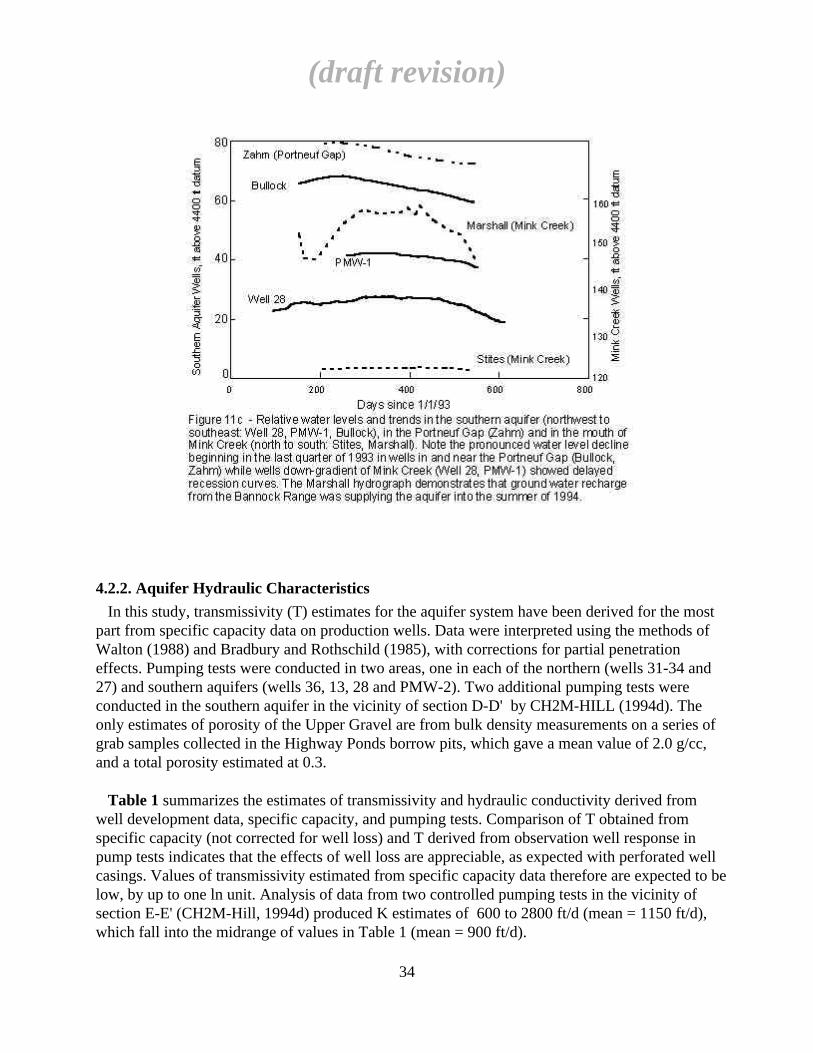
4.2.2. Aquifer Hydraulic Characteristics
In this study, transmissivity (T) estimates for the aquifer system have been derived for the mostpart from specific capacity data on production wells. Data were interpreted using the methods of Walton (1988) and Bradbury and Rothschild (1985), with corrections for partial penetrationeffects. Pumping tests were conducted in two areas, one in each of the northern (wells 31-34 and27) and southern aquifers (wells 36, 13, 28 and PMW-2). Two additional pumping tests wereconducted in the southern aquifer in the vicinity of section D-D' by CH2M-HILL (1994d). Theonly estimates of porosity of the Upper Gravel are from bulk density measurements on a series ofgrab samples collected in the Highway Ponds borrow pits, which gave a mean value of 2.0 g/cc,and a total porosity estimated at 0.3.
Table 1 summarizes the estimates of transmissivity and hydraulic conductivity derived fromwell development data, specific capacity, and pumping tests. Comparison of T obtained fromspecific capacity (not corrected for well loss) and T derived from observation well response inpump tests indicates that the effects of well loss are appreciable, as expected with perforated wellcasings. Values of transmissivity estimated from specific capacity data therefore are expected to below, by up to one ln unit. Analysis of data from two controlled pumping tests in the vicinity ofsection E-E' (CH2M-Hill, 1994d) produced K estimates of 600 to 2800 ft/d (mean = 1150 ft/d),which fall into the midrange of values in Table 1 (mean = 900 ft/d).
(draft revision)
34

(draft revision)
35
TABLE 1 - Transmissivity and hydraulic conductivity estimates for the Lower Portneuf River Valley aquifer from well development data, specific capacity estimates and aquifer pumping tests. Calculations incorporate partial penetration correction (W alton, 1988, p.19). Results flagged with asterisk for Katsilometes and LDS farm irrigation well pumping tests are from CH2M-Hill (1995). Bolded entries indicate most reliable data.
Pump Draw- W ell Screen Aquifer Rate down radius Length Thickness Q/s Q/s
W ell # Test Date (gpm) s(ft) r(ft) Ls(ft) b(ft) U/C (raw) corr'd T,ft2/s ln(T) K (ft/day)---------------------------------------------------------------------------------------------------------------------------------------------------------------------------------SOUTH AQUIFER:
13 12/53, no info; 2 hr 450 0.67 0.58 35 80 U 672 458 1.05 0.053 113813 05/87, pump check 1150 2.2 0.58 35 80 U 523 357 0.82 -0.198 88613 12/53, no info; 2 hr 525 0.75 0.58 35 80 U 700 478 1.10 0.094 1186
28 production 7/88 1200 1.25 0.75 50 60 U 960 1047 2.41 0.878 346528 1/21/71 const rate, 11 hr 2100 3 0.75 50 60 U 700 763 1.75 0.562 252728 1/21/71 const rate, 8 hr 2100 3 0.75 50 60 U 700 763 1.75 0.562 252728 production 7/91 856 1 0.75 50 60 U 856 933 2.15 0.763 3090
30 production 7/91 1400 1.5 0.83 50 65 U 933 991 2.28 0.823 302730 production 7/89 1400 2 0.83 50 65 U 700 743 1.71 0.535 227030 2/11/80 const rate, 3 hr 1000 2.3 0.83 50 65 U 435 461 1.06 0.059 1410
33 1965, no information 2000 33 0.5 50 70 U 61 57 0.13 -2.025 163
36 3/17/93 const rate, 29 hr 3000 1.15 0.83 50 100 U 2609 2004 4.61 1.527 398036 recovery test, 3/17/93 3000 NA NA NA 100 U NA NA 5.5 1.705 475236 pump test11/8/93, 3 obs.wells 1100 NA NA NA 100 U NA NA 7.50 2.015 648036 " " " underdamped analysis NA NA NA 100 U NA NA 11.5 2.442 9936
Turner N. end Ross Park 8/20/52 no information 1415 1.14 0.67 50 60 U 1241 1336 3.07 1.122 4422
Katsilometes 7/8/94, step drawdown tests* 1000 4.27 0.5 50 70 U 234 222 0.51 -0.673 629Katsilometes " " " 1600 10.46 0.5 50 70 U 153 145 0.33 -1.099 411Katsilometes " " " 2050 16.8 0.5 50 70 U 122 116 0.27 -1.325 328Katsilometes 7/8/94 pump test, 48 hr.* 2000 NA 0.5 50 70 U NA NA 0.67 -0.400 827PA-9 " " " obs well NA 0.167 NA 70 U NA NA 2.29 0.829 2827PA-9 " " " obs well NA 0.167 NA 70 U NA NA 0.67 -0.400 827PA-10 " " " obs well NA 0.167 NA 70 U NA NA 0.68 -0.386 839
PA-5 5/14/94, 48 hr, pump test on obs well NA 0.167 NA 120 U NA NA 0.84 -0.174 605PA-5 LDS Farm, north well* obs well NA 0.167 NA 120 U NA NA 0.93 -0.073 670
Averages: 2.22 0.29 Std. Dev'n: 2.87 1.01
CENTRAL AQUIFER:
12 12/06/54 const rate, 11 hr 2075 1.9 0.83 55 90 U 1092 975 2.24 0.807 215112 production 7-8/89 2343 2 0.83 55 90 U 1172 1046 2.40 0.877 230812 12/07/54 const rate, 8 hr 2250 2 0.83 55 90 U 1125 1004 2.31 0.836 221612 production 8/90 2300 2 0.83 55 90 U 1150 1026 2.36 0.858 226512 5/06/56 2400 2.3 0.75 55 90 U 1043 917 2.11 0.746 202312 production 8/90 2600 2 0.83 55 90 U 1300 1160 2.67 0.981 2561
16 12/03/60 const rate, 2 hr 2170 3.7 0.83 33 90 U 586 370 0.85 -0.163 81616 production 8/91 1250 3 0.83 33 90 U 417 263 0.60 -0.505 58016 12/02/60 const rate, 1 hr 2790 8.2 0.83 33 90 U 340 214 0.49 -0.707 473
10 production 7/90 2358 1.2 0.83 75 120 U 1965 1705 3.92 1.366 282210 production 8/90 2142 1.2 0.83 75 120 U 1785 1549 3.56 1.270 256310 production 7-8/90 2172 1.25 0.83 75 120 U 1738 1507 3.47 1.243 2495
29 4/27/73 const rate, 72 hr 2500 35 0.83 190 200 C 71 74 0.23 -1.473 99
9 post-1948, no info, Q est'd 300 15 0.83 50 120 20 13 0.03 -3.505 22 Averages: 1.95 0.19 Std. Dev'n: 1.24 1.31
NORTHERN AQUIFER:
26 4/25/92, production, 1 obs.well 2400 NA NA NA 60 NA NA 4.7 1.548 676826 3/15/92, production, 2 obs.well 2400 NA NA NA 60 NA NA 2.9 1.065 4176
27 " " obs NA NA NA 150 NA NA 1.5 0.405 86427 3/28/92, production, 1 obs.well 1200 NA NA NA 150 NA NA 3.3 1.194 1901
31 4/08/77 const rate, >24 hr 3800 7 0.83 82 82 C 543 554 1.72 0.540 1805
34 5/21/93, pump test,1 obs.well 3100 NA NA NA 120 NA NA 3 1.099 216034 4/26/93, pump test,1 obs.well 3100 NA NA NA 120 NA NA 3.2 1.163 230434 4/14/93, pump test,1 obs.well 3100 NA NA NA 120 NA NA 2.6 0.956 187234 5/02/93, pump test,1 obs.well 3100 NA NA NA 120 NA NA 2.2 0.788 1584
8 4/19/53 const.rate, 8 hr 1700 86.4 0.67 135 250 C 20 14 0.04 -3.165 15 Averages: 2.52 0.56 Std. Dev'n: 1.19 1.28
EASTERN AQUIFER:
15 10/18/77 const rate 3600 6 0.83 25 50 U 600 528 1.21 0.193 2096
Number of Estimates: 56 56 Averages: 2.16 0.36 Std. Dev'n: 1.91 1.12

Analysis of drawdown responses in wells 26, 27, 31 and 34 indicates an apparent T of 1.5 - 4.7ft2/sec (K = 860 - 6800 ft/d) with an apparent storativity of 0.000002-0.000009. This is consistentwith the confined nature of the upper and lower water-bearing zones tapped by these wells (Figure5). The mean T determined for these wells is approximately one ln unit higher than the mean of allavailable T estimates. Drawdown responses in wells 36, 13, 28 and PMW-2 indicated the highesttransmissivities in the entire aquifer system. Using curve matching and Jacob straight-line analysisof data from the first four hours of the drawdown phase, values of T = 7.5 ft2/sec (K = 6500 ft/d)and S = 0.005 were obtained.
As shown in Figure 12, the drawdown response of well PMW-2 at a distance of 45 ft from thepumping well demonstrated classic underdamped response, characteristic of porous media of veryhigh-transmissivity (van der Kamp, 1976). Utilizing van der Kamp's equations and an iterativecurve-fitting method to determine the frequency and damping constant of the well-aquiferoscillatory response, a value of T = 11.5 ft2/s (K = 10000 ft/d) was obtained, which is in goodagreement with the results from conventional methods of pumping test data analysis consideringthe differences in analysis methods and assumptions.
The results summarized in Table 1 indicate that the hydraulic conductivity in the vicinity of Well36 is the highest in the entire aquifer. It is possible that the narrow, notch-like character of thepaleovalley in this location (Figure 6b) served to focus fluvial energy and resulted in thedeposition of generally coarser, better-sorted gravels. If so, a similar situation may exist in themodern Portneuf Gap, suggesting that higher-K gravels may exist in the Gap than are present inthe bulk of the southern aquifer.
The pumping test on Well 36 (Figure 12) defined the presence of an impermeable flow boundaryat a distance of 600-800 ft (183-244 m) from the pumping well that is consistent with the well'sdistamce from bedrock (cf. Figure 6b), but this test was of too short a duration to identify theinfluence of possible river recharge. However, pumping tests conducted in the vicinity of sectionE-E' have corroborated the limited hydraulic impact that the river has on the Upper Gravel aquifer(CH2M-Hill, 1994c perform search-and-replace on "1994d", revise "1994c" where appropriate).
The test on well 36 also indicated that the aquifer behaves in a confined or semi-confinedmanner, with observation wells 2500 ft away responding instantaneously to the start of pumping.In addition, the agreement between transmissivity estimates obtained with conventional analysisand with equations developed to describe the underdamped response in confined situations (vander Kamp, 1976) also suggests that the aquifer may partially confined in the vicintiy of Well 36;this would be consistent with the barometric responses observed in wells 36, 13 and, to a lesserdegree, well 28 (Figure 11a).
Analysis of pumping test data near section E-E' suggested that substantial lateral hydraulicanisotropy (4:1) may exist in the Upper Gravels (CH2M-Hill, 1994c). That shallow, multi-welltest, with the Katsilometes well pumping and the PA-series wells monitoring, was conducted inthe interval between 30 and 66 ft bls. Wells PA-9 and 10 monitored the depth intervals 57-67/87-97 and 22-62, respectively. Because PA-9's completion spans two depth zones, its apparent
(draft revision)
36
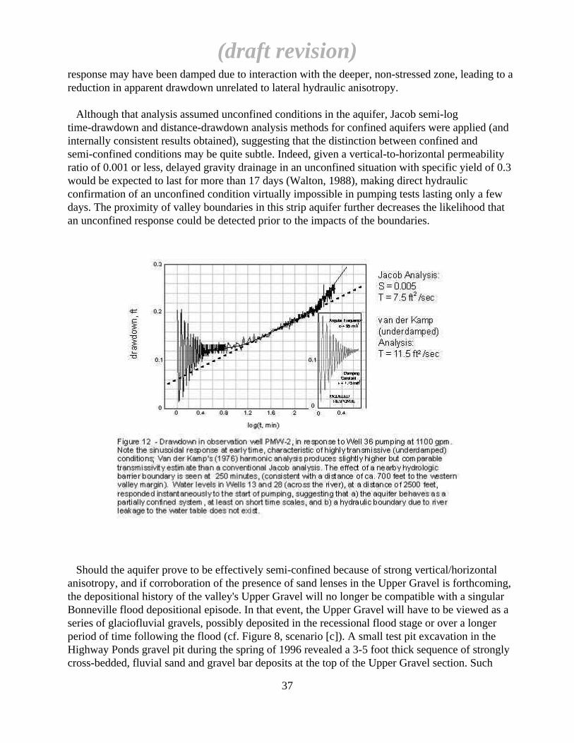
response may have been damped due to interaction with the deeper, non-stressed zone, leading to areduction in apparent drawdown unrelated to lateral hydraulic anisotropy.
Although that analysis assumed unconfined conditions in the aquifer, Jacob semi-logtime-drawdown and distance-drawdown analysis methods for confined aquifers were applied (andinternally consistent results obtained), suggesting that the distinction between confined andsemi-confined conditions may be quite subtle. Indeed, given a vertical-to-horizontal permeabilityratio of 0.001 or less, delayed gravity drainage in an unconfined situation with specific yield of 0.3would be expected to last for more than 17 days (Walton, 1988), making direct hydraulicconfirmation of an unconfined condition virtually impossible in pumping tests lasting only a fewdays. The proximity of valley boundaries in this strip aquifer further decreases the likelihood thatan unconfined response could be detected prior to the impacts of the boundaries.
Should the aquifer prove to be effectively semi-confined because of strong vertical/horizontalanisotropy, and if corroboration of the presence of sand lenses in the Upper Gravel is forthcoming,the depositional history of the valley's Upper Gravel will no longer be compatible with a singularBonneville flood depositional episode. In that event, the Upper Gravel will have to be viewed as aseries of glaciofluvial gravels, possibly deposited in the recessional flood stage or over a longerperiod of time following the flood (cf. Figure 8, scenario [c]). A small test pit excavation in theHighway Ponds gravel pit during the spring of 1996 revealed a 3-5 foot thick sequence of stronglycross-bedded, fluvial sand and gravel bar deposits at the top of the Upper Gravel section. Such
(draft revision)
37
evidence supports the view that some portion of the Upper Gravel is post-flood and may be farmore heterogeneous and anisotropic than initially presumed.
Utilizing a K range of 1000 - 5000 ft/d, a hydraulic gradient of 0.0015, and a total cross-sectionalarea for underflow through the Upper Gravel in section C-C' of 2.5 x 105 ft2, ground waterunderflow past C-C' is estimated to be between 4 and 22 ft3/sec. Comparing this flux with theannual average continuous pumping rate from the entire well field of ca. 20 ft3/sec indicates thatpumping withdrawals have a major impact on the aquifer's water balance and storage potential.Assuming an effective porosity of 0.3, the linear flow velocity in the southern aquifer is in therange of 5-25 ft/day.
(draft revision)
38
5. GROUND WATER QUALITY
5.1. HISTORIC WATER QUALITY TRENDS
The City of Pocatello has maintained water quality records on its production wells since themid-1960's. On the whole, inorganic water quality has been characteristically good, although thewater is very hard and has a relatively high total dissolved solids (TDS) content. Closerexamination of water quality records shows that ground water quality varies in a systematicmanner that suggests that point and/or non-point sources are adding chloride and sulfate salts tothe aquifer in a coupled fashion. In particular, the water quality of the eastern alluvial aquifer (eastof the Portneuf Basalt; Figure 4) is poor and is characterized by high concentrations of chloride,sulfate and nitrate. However, because of the lack of production wells in this area and because thefocus of this study has been on understanding the geohydrology of the main aquifer, relatively littlewater quality information on the eastern aquifer exists. A recent report documents some of thewater quality problems that characterize the eastern system (Winter et al., 1994) and this, togetherwith unpublished M.S. thesis research work by ISU Geology student C. Meehan, constitutes thebulk of our knowledge of the water quality of the eastern system.
5.1.1. Overview of Production Well Data
Figure 13 shows the overall composition of water from Pocatello production wells as Piper(trilinear) plots in selected years. Data are from water quality records on file with the City ofPocatello and the IDEQ. In general, the bulk composition of cationic constituents has remainedfairly constant both spatially and temporally (with perhaps a slight tendency to increasing relativesodium content in latter years), while the proportion of sulfate and chloride has shown apronounced variation spatially over the aquifer. In general, portions of the northern aquifer and thealluvial aquifer east of the Portneuf Basalt (Figure 4) have the highest concentrations of salts,including nitrate. Wells 2 and 3, at the northwest end of the basalt, also have had chronicallyhigher salt and nitrate.
Figure 14 is a comparative plot of relative abundances of major anions, showing consistentlyincreasing proportions of Cl and SO4 in Pocatello production wells with time. As shown in Figure15, these trends are mimicked by various other inorganic constituents, including TDS, majorcations, hardness, alkalinity and nitrate. Such trends in the historical data can be observed back to1966, at least, although the earliest records indicate that nitrate is neither significantly elevated norcorrelated with chloride, and that the range in dissolved salt concentrations is much smaller than inrecent times.
5.1.2. Temporal and Spatial Trends in Historic Data
Evidence for a temporal trend towards increasing salt concentrations is strikingly evident in thehistorical record, although only portions of the aquifer system have been significantly affected.Figure 16 shows variations of chloride in selected Pocatello production wells from 1966, theearliest year of record, to the present. Although some of the earlier data's quality is suspect (as, forexample, some analyses from 1974), the trends shown in Figure 16 are echoed in most major ionicconstituents. Thus, the available data indicate that past variations of dissolved salt content in the
(draft revision)
39
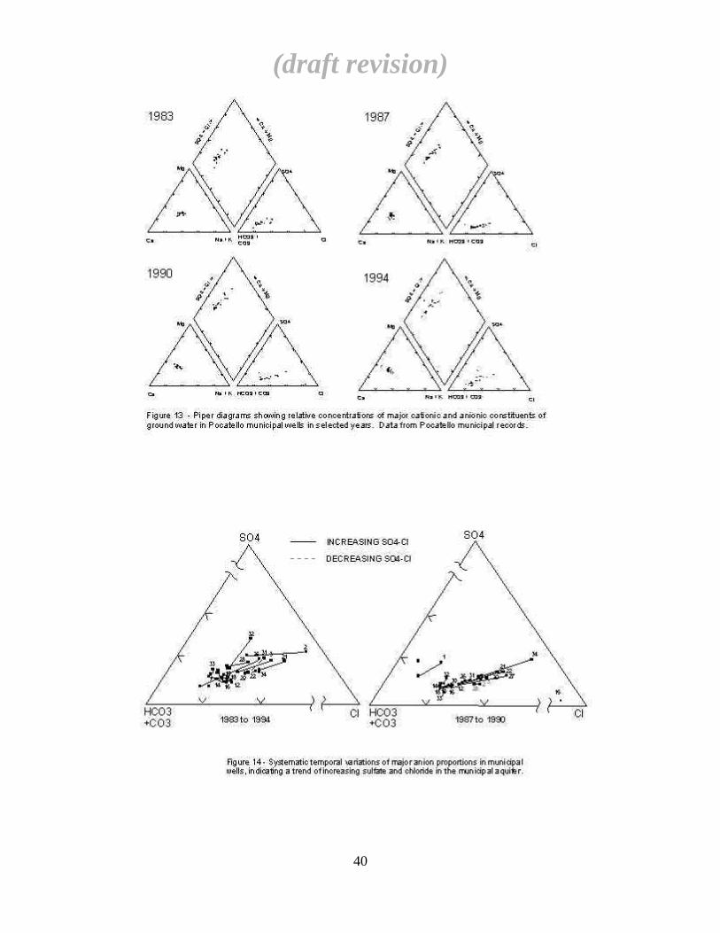
(draft revision)
40

(draft revision)
41
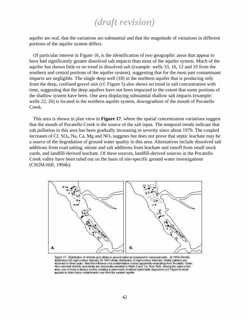
aquifer are real, that the variations are substantial and that the magnitude of variations in differentportions of the aquifer system differs.
Of particular interest in Figure 16, is the identification of two geographic areas that appear tohave had significantly greater dissolved salt impacts than most of the aquifer system. Much of theaquifer has shown little or no trend in dissolved salt (example: wells 33, 16, 12 and 10 from thesouthern and central portions of the aquifer system), suggesting that for the most part contaminantimpacts are negligible. The single deep well (18) in the northern aquifer that is producing onlyfrom the deep, confined gravel unit (cf. Figure 5) also shows no trend in salt concentration withtime, suggesting that the deep aquifers have not been impacted to the extent that some portions ofthe shallow system have been. One area displaying substantial shallow salt impacts (example:wells 22, 26) is located in the northern aquifer system, downgradient of the mouth of PocatelloCreek.
This area is shown in plan view in Figure 17, where the spatial concentration variations suggestthat the mouth of Pocatello Creek is the source of the salt input. The temporal trends indicate thatsalt pollution in this area has been gradually increasing in severity since about 1970. The coupledincreases of Cl, SO4, Na, Ca, Mg and NO3 suggests but does not prove that septic leachate may bea source of the degradation of ground water quality in this area. Alternatives include dissolved saltadditions from road salting, nitrate and salt additions from leachate and runoff from small stockyards, and landfill-derived leachate. Of these sources, landfill-derived sources in the PocatelloCreek valley have been ruled out on the basis of site-specific ground water investigations(CH2M-Hill, 1994b).
(draft revision)
42

The second area of substantial salt impact shown in Figure 17 (wells 2, 3, 28 in Figure 16)occurs near the northern end of the southern aquifer, where the Portneuf Basalt terminates. Thisarea of the municipal aquifer may be affected by the capture of salt- and nitrate-contaminatedground water from the eastern alluvial aquifer, which is known to be heavily contaminated bythese constituents (IDEQ, 1994). Wells 2 and 3 historically have maintained essentially year-roundproduction from this area of the aquifer, and therefore may have created a chronic hydraulic sinkwhich has created a substantial capture zone for upgradient salt contamination, particularly fromareas east of the basalt. Municipal well 15, which is situated on the opposite side of the basalt fromwell 28, was abandoned in the early 1980's because of excessive nitrate; it has also had the highestchloride and sulfate concentrations of any Pocatello municipal well on record (Cl = 732 and SO4 =2245 mg/l in 1980).
From an examination of the historical data it is concluded that: a) a large portion of the northern aquifer system is affected by salt pollution from anunidentified source but which apparently originates in the Pocatello Creek area; b) most of this salt probably originates from shallow and/or surface sources, and that the deepportion of the aquifer system may yet be free of contaminants; and c) for the most part, the southern aquifer appears not to have been substantially affected by theaddition of chloride, sulfate and nitrate, except in localized areas along the eastern margin and inthe vicinity of some private wells.
5.2. CURRENT WATER QUALITY TRENDS
5.2.1. Water Quality Trends in the Southern Aquifer
Figure 18 is a plot of all well locations in the southern aquifer study area that were sampled aspart of C. Meehan's M.S. thesis research in support of the WHP aquifer characterization program.A large number of wells were sampled in order to identify, and to provide a representative numberof analyses of, the different water sources that are potentially recharging the aquifer. Pending theidentification of a sufficient spread of water compositions and concentrations, this informationcould be used to calculate independent chemical mass balances for the aquifer, and hence to solvefor unknown water recharge fluxes.
Constituents that were analyzed include: field pH, specific conductance and temperature; totalhardness by EDTA titration; total alkalinity by acid titration; Na and K by atomic absorptionspectrophotometry; Mg, Cl, and NO3 by spectrophotometry, and SO4 by turbidimetry. Allanalytical methods are by Hach, Inc. analytical protocols, except for Na and K. Analyticalmethods, precision and detection limits are summarized in Meehan and Welhan (1994) and will bedetailed in C. Meehan's thesis.
A Piper plot of the part of the major ion data acquired during 1993 and 1994 is shown in Figure19. As is apparent from the plot, several different water types exist in the study area but, except forwaters from the nitrate and salt-contaminated eastern aquifer, the compositional fields for these
(draft revision)
43

(draft revision)
44
waters overlap to a large extent. However, there are several notable features of this data set thatcan be exploited in a chemical mass balance approach.
First, there are only three distinctly different potential recharge water types associated with threedifferent sources: Portneuf River water, the eastern aquifer, and waters of the Bannock Range(which includes Mink Creek, Gibson Jack, City and Cusick Creek drainages). The largestcompositional variation is seen in the Bannock Range waters, probably reflecting a spectrum ofdifferent water-rock chemical exchange reactions that would be expected in the varied geologicsetting of the Bannock Range, which includes such chemically diverse rock types as limestone,volcanic ash and quartzite.
Second, aside from this minor compositional diversity, essentially all Bannock Range waters arelow in TDS and, therefore, are chemically distinct from the main aquifer's ground water. Becauseof the concentration contrast between Bannock Range waters, other potential rechargecomponents, and southern aquifer water, their ionic contents are amenable to the development ofindependent chemical mass balance equations, which, together with the hydrologic mass balanceequation, can be used to solve for unknown water flux terms in the hydrologic mass balance. Third, the chemical composition and major ion concentrations of Portneuf River water are verysimilar to those of the southern aquifer, thus rendering the independent solution of a possible riverrecharge flux term impossible on the basis of chemical compositions, alone. However, the stableisotopic composition of surface water tends to be different from ground waters because ofevaporation (Gat, 1970), particularly during the summer when upstream diversions and enhancedevaporation can produce a significant increase in a stream's stable oxygen-18 content. The oxygenisotope composition of a number of waters in the study area were analyzed as part of anNSF-sponsored research project investigating the hydrology of the Mink Creek watershed (Table2). As is evident, the Portneuf River's composition is significantly different from other potentialrecharge sources. Since only one sample of river water has been analyzed (July, 1994 collection),it is not known whether the value shown in Table 2 is representative or anomalous. On the basis ofthis single sample, it would appear that river water contributed half of the total recharge to theaquifer, which contradicts several other lines of evidence (Section 6). More samples will becollected under winter baseflow and spring, 1995 runoff conditions. If the oxygen-18 compositionof the river during spring runoff proves to be similar to that shown in Table 2, the contribution ofriver leakage to the water balance of the southern LPRV aquifer could be significant.
5.2.2. Chemical Mass Balance Approach
The chemical mass balance approach being taken by C. Meehan in his M.S. thesis researchrepresents work in progress, and is summarized only briefly in this report. The method involvesdefining the following balance equations:
dV/dt = Qg + Qr + Qb + Qe - Qp - Qo
d(CioV)/dt = Ci
gQg + CirQr + Ci
eQe - CioQp - Ci
oQo
(draft revision)
45

where V is the volume of the southern aquifer, the Q's are the rates of water inflow through thePortneuf Gap (g) and from the river (r), the Bannock Range (b), the eastern aquifer (e) and outflowfrom pumping (p) and underflow (o) across the bedrock high at Section B-B'; the Ci
j termsrepresent the concentrations of conservative chemical and isotopic species (i) of the various waterinflow and outflow components (j). In the approach used in this study, these conservative speciesare considered to be Cl, SO4, NO3 and oxygen-18. Nitrate was included because all waters in thesystem are believed to be oxidizing and chemical or microbial nitrogen transformations areassumed to be negligible during the residence time of water and nitrate in the southern aquifer.
Preliminary interpretation of the chemical mass balance of the aquifer suggests that BannockRange waters constitute a significant part of the overall recharge to the southern aquifer and thatPortneuf River leakage is not a major contributor. If verified through more detailed modeling ofthe aquifer's chemical mass balance, these interpretations would be consistent with water levelresponses observed in the main aquifer and in Mink Creek valley, and with geohydrologicevidence obtained in aquifer pumping tests to date. However, the chemical balance approachshould not be expected to provide a definitive quantification of aquifer recharge, because of theuncertainty in defining the average chemical concentrations of potential recharge sources that mayoriginate over a wide area (eg: Bannock range waters) and sources whose chemistry varies widelyand/or is poorly defined (eg: eastern aquifer contaminated waters). For example, the historical dataexamined in preceding sections indicate that Cl and SO4 impacts from local contamination sources
(draft revision)
46
TABLE 2 - Stable oxygen isotope data on ground waters in the Lower Portneuf River Basin, collected June-July, 1994.
Sample ID O-18, per m il--------------------------------------------------------------------Southern and Central Aquifer:W ell 36 -16.8W ell 12 -16.75W ell 2 -16.8PA-4 -16.8Pa-7 -16.7 Average:Pa-9 -16.9 -16.77
Bannock Range and Related W aters:Hayden/Stites(composite) -17.4Pearson -17.8Strawn -18Kelley -17.9City Creek (mouth) -17.7Pein -17.7 Average:B ickley -18 -17.78571
Portneuf Gap Ground W ater Inflow:Zahm -16.9
Eastern Aquifer:Composite of three wells -17.4
Portneuf River -15.7

are significant in certain areas of the aquifer system, possibly rendering these tracers unsuitable formass balance calculations in a simplified, regional recharge mass accounting.
5.2.3. Evidence for Local Contamination Sources in the Southern Aquifer
Figure 20 is a plot of chloride concentrations in the southern aquifer, as defined by C. Meehan'ssampling in May-July, 1994. This sampling was intended to identify anomalous concentrations ofconservative anions that were intended to be used as mass balance tracers and to define possiblespatial variations in the southern aquifer, analogous to those observed on a regional scale (eg:Figure 17), which could deleteriously affect the mass balance interpretation.
Several localized high-Cl anomalies are observed (marked by dashed circles), including onewhich defines a small plume (in the vicinity of Tech Farm Road). These high-Cl occurrences areinterpreted as localized sources of ground water contamination, originating at or near the surface.Possible sources of this contamination include salt runoff from road de-icing, septic field leachate,and agricultural (animal) waste. Chloride, sulfate and nitrate are all positively correlated which issuggestive of an anthropogenic. The point-source nature of the contamination suggests thatsurface-derived contaminants may be reaching the aquifer via leakage along poorly-sealed wellcasings or through abandoned, open wells. The former is known to be a chronic and wide-spreadproblem throughout southeastern Idaho, due to lack of sufficient enforcement of water welldrilling and completion regulations, and the latter is suspected in at least one case (the Tech FarmRoad plume) where anecdotal information is available regarding rapid, localized percolation ofcorral runoff which is suggestive of an abandoned well.
(draft revision)
47

Since the high-Cl values (indicative of localized, point-source contamination) would tend toskew a natural, homogeneous aquifer Cl distribution, the normal Cl distribution observed in thissystem suggests that low-Cl waters must also be involved. This gives rise to two possibilities: 1)ground water chemical composition is spatially inhomogeneous over the southern aquifer or 2) thesamples are drawn from more than one population or source water.
5.2.4. Evidence for Contribution of a Low-TDS Water to the Southern Aquifer
Figure 21 is a cross-plot of sulfate vs chloride concentrations in the southern aquifer, for thesame wells plotted in Figure 20. Two features are noteworthy: a) 66% of the samples clusterrelatively tightly about a mean chloride concentration of 58 mg/l, with a small number of samplesshowing much higher concentrations (representing those wells contaminated by leakage fromnear-surface sources); and b) a number of samples showing lower concentrations, with a fewhaving very low Cl and SO4 concentrations. The low-concentration samples are similar to waterssampled from the Bannock Range (Figure 19), which are low in Cl, SO4 and NO3, and indicate thatthese wells may be drawing their water from this type of source. In fact, of eight low-sulfate (<30mg/l) wells completed in the southern aquifer proper, the well logs of at least four confirm that thewells are completed partially or fully in Tertiary Starlight Formation cemented gravels; in addition,several other wells with SO4 < 30 mg/l on the west pediment gravels are also tapping BannockRange water directly.
Nitrate is fully correlated with chloride in these wells, and provides further evidence that thelow-Cl, SO4 and low-NO3 waters observed in the southern aquifer are due to mixing with a
(draft revision)
48
low-nitrate source, such as the Bannock Range end-member, rather than to mixing with relativelylow-TDS Portneuf River water which has appreciable nitrate. On the basis of the above data, therefore, it is proposed that the aquifer is receiving rechargefrom Bannock Range sources, and that this recharge is entering the aquifer via lateral leakage. Apaired set of shallow and deep observation wells in Section E-E' (Figure 7b) shows a small butsignificant upward vertical hydraulic gradient between the Tertiary sediments and the UpperGravels (CH2M-Hill, 1994d). This same deep well contains low-TDS water which indicates thatBannock Range recharge is entering the aquifer from below as well as laterally.
5.2.5. Chemical Impacts of Chloride and Sulfate in the Southern Aquifer
The source(s) of the Cl and SO4 contamination observed in isolated wells in the southern aquiferremains unknown, although leakage of surface waters contaminated by septic leachate, animalwastes and/or road salt have been proposed as possibilities. What is clear, is that some privatewells have an unmistakable impact on the water quality of the aquifer, apparently by providing aconduit for leakage of contaminated surface waters to the aquifer. This may be through poorsurface casing seals, improper pitless adapter wellhead completions and/or open, abandoned wellbores.
High concentrations of Cl and SO4 that have been recorded in domestic wells in the easternaquifer (Cl to 490 mg/l, SO4 to 220 mg/l) have also been seen in the Pocatello Creek valley (Cl to1500 mg/l, SO4 to 2000 mg/l), where they have been attributed to contamination by winter roadsalt runoff from Pocatello Creek Road (CH2M-Hill, 1994b). Coupled increases of Cl and SO4
observed in parts of the southern aquifer have been proposed to be the result of a combination ofroad salt runoff and leaching of a soluble calcium-sulfate component in roadbed aggregate, whichmay also be a major factor in the Pocatello Creek area (Meehan and Welhan, 1994).
Meehan and Welhan's work has also suggested that other chemical effects due to the inputs ofroad salt and leachable sulfate, such as induced Ca-Na ion exchange, carbonate precipitationreactions and common-ion competition, may substantially alter the cationic abundances in theseground waters. For example, in Figure 15, where the Na-Cl trend is lower than that expected forthe addition of pure NaCl, ion exchange may be responsible for Na removal from solution with anaddition of Ca and Mg to maintain charge equilibrium. If NaCl were the sole salt source, theobserved 110 mg/l increase in Cl in Figure 15 would result in a Na increase of about 72 mg/l.However, only a 42mg/l increase in Na is observed, leaving a deficit of 30 mg/l (1.30 meq/l). On acharge-equivalent basis, the increases in Ca (45 mg/l or 2.2 meq/l) and Mg (not shown in Figure15; 8 mg/l or 0.67 meq/l) more than balance the Na deficit. Since the quality of the analytical datais unknown and since the use of mixed calcium-sodium chloride salts may be responsible for someof the "excess" Ca, the data are not inconsistent with the hypothesis that cation exchange is animportant buffering process in this aquifer system.
(draft revision)
49

6. AQUIFER WATER BALANCE
6.1. PRINCIPLE RECHARGE SOURCES
6.1.1. Precipitation
Table 3 summarizes mean annual temperature, humidity and precipitation as recorded at thePocatello Airport meteorological station. The period encompassed by this study includes a year ofabove-average precipitation (1993) and one of below-average precipitation (1994). Precipitation inthe lower basin varies from less than 15 inches (38 cm) in the Portneuf River valley to more than30 inches (76 cm) in the Bannock Range (Figure 22). A precipitation station at Wild Horse Divideat an elevation of 6526 ft (1990 m) in the southern Bannock Range has averaged 29.7 inches (75.4cm) over 11 years of record. As shown in Figure 22, precipitation over the Bannock Range is thenearest potential source of local recharge to the LPRV aquifer system, other than underflow fromthe upper Portneuf basin through the Portneuf Gap, and likely plays a significant role in theaquifer's water balance.
(draft revision)
50
TABLE 3 - Summary of Meteorological Data, from National Weather Service, Pocatello Airport Weather Station. Years of historical record on which means are based are shown in parentheses.
Mean Temperature, F (44 years):---------Annual--------
Jan Feb Mar Apr May Jun Jul Aug Sept Oct Nov Dec Mean 1993 199424 29.3 37 46 54.4 62.81 71.4 69.6 59.7 48.8 36.1 26.6 47.2 43.2 48.4
Mean Snowfall, inches (44 years):---------Annual--------
Jan Feb Mar Apr May Jun Jul Aug Sept Oct Nov Dec Mean 1993 199410 6.2 5.9 4.4 0.6 T 0 T 0.1 1.9 5.3 8.9 43.2 93.3 31.6
Mean Total Precipitation, inches (44 years):---------Annual--------
Jan Feb Mar Apr May Jun Jul Aug Sept Oct Nov Dec Mean 1993 19941.18 1.01 1.23 1.27 1.36 1.05 0.65 0.7 0.81 0.98 1.03 1.06 12.32 17.88 9.08
Mean Daytime Relative Humidity, % (30 years):---------Annual--------
Jan Feb Mar Apr May Jun Jul Aug Sept Oct Nov Dec Mean 1993 199473 66 56 43 39 37 30 29 33 42 63 73 49 53
Mean Wind Speed, mph (44 years):---------Annual--------
Jan Feb Mar Apr May Jun Jul Aug Sept Oct Nov Dec Mean 1993 199410.6 10.6 11.2 11.7 10.6 10.1 9.1 8.9 9.1 9.3 10.3 9.9 10.1 9.2
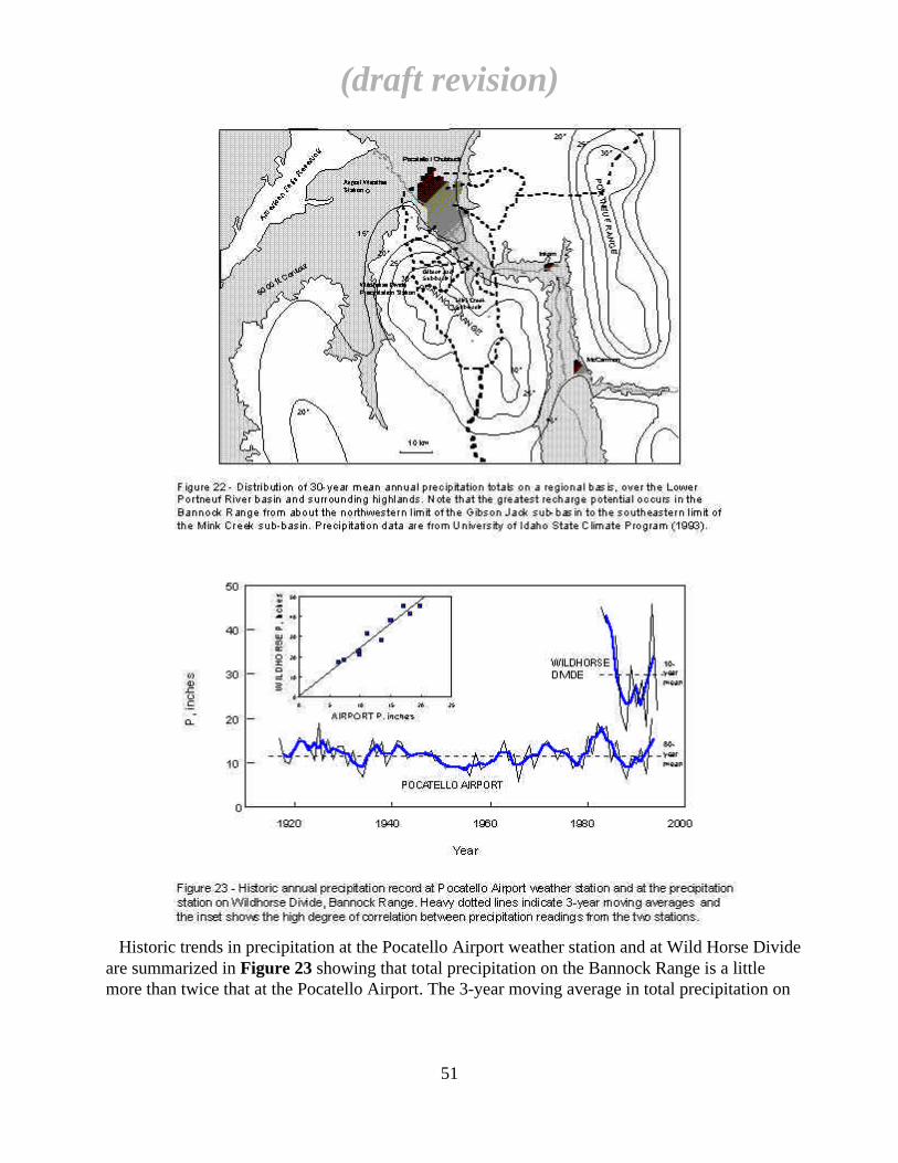
Historic trends in precipitation at the Pocatello Airport weather station and at Wild Horse Divideare summarized in Figure 23 showing that total precipitation on the Bannock Range is a littlemore than twice that at the Pocatello Airport. The 3-year moving average in total precipitation on
(draft revision)
51

the Bannock Range might be expected to mimic the aquifer system's storage variations, and thevariation in Wildhorse Divide precipitation during the 1980s coincides with the high ground waterlevels seen in aquifer wells in Figure 10. The synchronicity between local potential recharge (inthe form of Bannock Range precipitation) and aquifer storage suggests that an important part ofthe aquifer's recharge may be locally derived in the Bannock Range.
6.1.2. Other Potential or Suspected Recharge Sources
Besides runoff and ground water underflow from the high-precipitation region on the BannockRange, the aquifer's other major potential recharge components are summarized in Figure 24. Inthis figure, Bannock Range recharge from Mink Creek, Gibson Jack Creek and the City-CusickCreeks sub-basins has been defined as a single component, Qb, because of the chemical similarityof these waters and our inability to separate individual source areas or zones of contribution to theaquifer on a chemical basis at this time.
The second major potential recharge source is flow from the upper Portneuf basin through thePortneuf Gap. This source of recharge may be distributed as ground water underflow through thePortneuf Gap and as river losses directly to the LPRV aquifer. Recharge from the upper basin maybe significant because of the size of the upper basin (1160 mi2 or 2970 km2) and the estimatedamount of precipitation the upper basin receives (19.6 in or 50 cm; Norvitch and Larson, 1970).
On the basis of Norvitch and Larson's data, a crude estimate of the water balance of the upperbasin can be made. Assuming a normal water year, an average basin-wide precipitation input of1670 ft3/s and an average discharge of the Portneuf River of 250 ft3/s, the net evaporative andconsumptive losses and ground water outflow from the upper basin would represent of the order of
(draft revision)
52
85% of the total basin recharge. Since estimated potential evaporation in this region is of the orderof 61 inches (155 cm) annually (CH2M-Hill, 1994d), or more than three times the mean annualbasin precipitation, it is to be expected that evaporative losses, alone, would constitute the largestcomponent of the net basin water loss and that ground water may not be a major component.
Of the potential for ground water outflow from the upper basin, Norvitch and Larson (1970)pointed out that annual mean discharge records on the Portneuf River indicated that approximately12 ft3/s was lost on an annual average basis to ground water underflow somewhere between thelower reach of the upper basin and in the LPRV. However, they believed that substantially morecould be lost to ground water, and estimated that this could be as high as 87 ft3/s.
Norvitch and Larson's adjusted estimate of apparent river loss hinged on an estimate of specificdischarge per unit basin area that was derived for the upper reaches of the basin and which wasapplied ad hoc to the lower reaches without justification. On the other hand, utilizing riverdischarge measurements made by those authors during the 1968 baseflow study period (which,curiously, they did not utilize in their analysis), there is no evidence whatsoever for significantriver losses between Inkom and Pocatello during baseflow times. Their measurements show that,at the confluence of Rapid Creek, Marsh Creek and the Portneuf River below Inkom, the totaldischarge of the Portneuf during December, 1968 was 245.5 ft3/s. Approximately 5.5 milesdownstream, immediately west of the Portneuf Gap, Portneuf River discharge was 247 cfs which,although slightly higher, is well within the uncertainties of the measurements. During the sametime, discharge measured at the downtown Pocatello gauging station was 252 ft3/s, again slightlyhigher because of Bannock Range tributary drainage contributions over the LPRV reach.
Norvitch and Larson did not measure the discharge of lower Portneuf basin tributary streams.We have measurements on Mink Creek, the largest lower Portneuf basin tributary, indicating adischarge of 1.65 ft3/s during the July, 1994 baseflow period (S. Van Hoff, pers. comm., 1994).Although 1994 was a dry year, this measurement suggests that the 5 ft3/s gain observed over thePortneuf's LPRV reach during baseflow of 1968 was due to tributary stream contributions, andreinforces the conclusion that Norvitch and Larson's measurements bear no indication of anysignificant river losses either above or below the Portneuf Gap.
The current mean annual discharge of the Portneuf River at Pocatello for the period of record is279 ft3/s (Harenberg et al., 1993), only slightly above the discharge regime that existed inDecember, 1968 when Norvitch and Larson made their stream discharge measurements. Since thePortneuf's mean discharge was near normal in 1993 (252 ft3/s) and below normal in 1994 (Figure11b), both years' mean discharges fall within a baseflow regime comparable to the measurementsof Norvitch and Larson. Therefore, by analogy with Norvitch and Larson's discharge data it isconcluded that 1) the Portneuf River was not losing significant amounts of water to leakage during1993-94 and 2) that ground water underflow through the Portneuf Gap was not a large componentof aquifer recharge during 1993-94.
The first conclusion is in keeping with the lack of hydraulic evidence for a substantialriver-aquifer connection (Section 4.2.2). The second conclusion is consistent with ground waterunderflow estimates made in Section 6.2.1, below. Both, however, leave open the possibility that
(draft revision)
53
river losses to the LPRV aquifer and ground water underflow through the Portneuf Gap may besignificant on a transient basis, such as during high river stage. In that case, the 12 ft3/s estimate ofNorvitch and Larson may reflect an approximate mean annual underflow through the Gap duringnormal or above-average water years.
Opinion regarding the Portneuf River as a losing stream is also shifting for other reasons. Duringthe past several years, informal surveys of the river have suggested that the ubiquitous carbonatedams that occur along the river above Pocatello, and that have been thought to be predominantly offossil hydrothermal origin, are actually actively growing algal reefs (J. Valcarce, pers. comm.,1993), whose existence may be closely tied to areas of inflow of carbonate-saturated groundwater. In addition, the extent and location of ice-free areas on the river during winter cold spellslends support to the contention that the river may experience substantial ground water gains, ratherthan losses (J. Valcarce, pers. comm., 1995).
Besides recharge from the Bannock Range, underflow through the Portneuf Gap and river losses,a fourth potential recharge source is included in the provisional water balance formulation,primarily on the basis of chemical considerations. In Section 5.1.2, the chemical composition ofthe shallow alluvial aquifer east of the Portneuf Basalt (the eastern aquifer) was shown to behighly contaminated with chloride, sulfate and nitrate salts. The influx of dilute Bannock Rangewaters, which are low in these constituents, have to be balanced by leakage from the easternaquifer or possibly another high-salt recharge source.
Although additional sources of recharge may also be involved, the current hydrogeologic modelof the basin is incapable of explicitly identifying them. For example, low-temperature thermalwater is known to occur in wells north of Pocatello Creek and in the Tyhee area north ofChubbuck and is likely an expression of fault-controlled deep circulation contributing smallamounts of water to the shallow ground water regime in that area (Corbett et al., 1980). The Tyheethermal waters are known to be elevated in sulfate and chloride relative to shallow ground waterand therefore represent a potential source of salinity in the shallow ground water system. If similarthermal waters recharge the southern valley, they may be responsible for part or all of the saltadded to the southern aquifer system, although their true contribution would be masked by leakageof shallow, contaminated water from the eastern aquifer.
6.2. WATER BALANCE
6.2.1. Physical Constraints
The physical water balance equation for the southern aquifer can be written as:
∆S =Qg + Qb + Qe +Qr - Qo - Qp
where the terms are as defined in Section 5.2.2 and Figure 24. Note that direct precipitation inputon the surface of the LPRV is implicitly neglected in this water balance formulation becausepotential evapotranspiration is so much higher than precipitation. The magnitudes of several ofthese terms can be adequately calculated on the basis of physical considerations, whereas otherscannot even be estimated (eg: Qb, Qe).
(draft revision)
54
In contrast, well water level records in the southern aquifer permit a reasonably accurate estimateof storage change (∆S). Likewise, pumping withdrawals (Qp) are well known from city productionrecords. Of the remaining terms, quantitative estimates of Portneuf Gap underflow (Qg) andsouthern aquifer outflow (Qo) can be made on the basis of cross-sectional aquifer geometry,hydraulic conductivity, and gradient. During low-flow conditions, the arguments presented inSection 6.1.2 indicate that river losses in the LPRV are negligible, leaving only Bannock Rangeinflow (Qb) and possible eastern aquifer leakage (Qe) as significant unknown terms. Duringperiods of high river discharge when river losses may be significant, Norvitch and Larson's (1970)estimate of 12 ft3/s Portneuf River loss through the Portneuf Gap can be assumed to represent totalunderflow through the Gap as well as potential river losses in the LPRV (i.e. Qg + Qr).
Based on the timing of recharge events, variations in pumping withdrawals and aquifer storagechanges shown in Figure 11b, three periods spanning some 17 months of available data werechosen for provisional water balance calculations. All are referred to subsequently in terms of "days since January 1, 1993" (as in Figure 11b). The first period, from Day 90-300 (April, 1993 -October, 1993) covers the only significant recharge event encountered during this study (theSpring, 1993 runoff) and also encompasses the peak well production period of 1993. The secondwater balance period, from Day 300- 450 (November, 1993 - March, 1994), encompasses a time inwhich Spring, 1994 runoff was dissapointingly low, southern aquifer production was low andaquifer water levels remained fairly constant or declined only slightly. The third, from Day450-600 (April, 1994 - August, 1994), covers 1994's period of peak pumping withdrawalaccompanied by a drastic aquifer storage decline, presumably because of the lack of significantrecharge . During the latter two periods, mean river discharge was within the regime in which thedata of Norvitch and Larson (1970) were interpreted as indicating negligible river losses in theLPRV (Section 6.1.2). Significant river losses are considered likely only in the first water balanceperiod when river discharge exceeded 300 ft3/s for about 100 days (Figure 11b).
Pumping Withdrawals
Of the terms in the water balance equation, four (Qp, Qg, Qo and ∆S) can be estimatedindependently. Pumping withdrawals were obtained from city Water Department records, anddischarges of wells pumping in the southern aquifer during the provisional water balance periodwere summed over the individual periods of the water balance. For example, during the periodDay 300-450, Qp was 0.353 billion gallons (Bgal) or 47.2 x 106 ft3; for Day 450-600, Qp was 0.79Bgal (105.6 x 106 ft3).
Aquifer Outflow
From a comparison of the aquifer cross-sections B-B' and C-C' shown in Figure 6, it wasconcluded that the greatest confidence in a physical underflow calculation could be obtained withsection C-C', because of the availability of hydraulic conductivity data for well 36 (obtained frompumping tests), a reasonable estimate of well 2's transmissivity (from specific capacity data; Table1), and because the cross-sectional geometry of C-C' is better defined than in B-B'. Also, theapparent saturated cross-sectional areas available for flow in the two sections raises an interestingpoint. Assuming continuity of mass for ground water flow between sections C-C' and B-B' and a
(draft revision)
55
hydraulic conductivity in the upper gravels no higher than that measured in well 36, the hydraulicconductivity of the putative Tertiary gravels in the lower part of B-B' would have to be higher thanthat of the upper gravels. Since this is unlikely given the very high permeability of the UpperGravel and the fact that the Tertiary gravels are characteristically silt and clay-rich, it follows thatsection B-B' must have a larger total saturated flow cross-section than is apparent in Figure 6.a.Furthermore, the western bedrock margin of the aquifer in Section C-C' is well-defined by gravitydata but not in B-B'. Therefore, section C-C' is considered the best-constrained cross-section forsouthern aquifer underflow calculations.
The maximum saturated cross-sectional area of section C-C' is calculated to be 2.5 x 105 ft2
during the second water balance period, with less than 4% variation during the lower water levelperiods. A hydraulic conductivity of 8000 ft/day (0.092 ft/s) and a hydraulic gradient of 0.001(lower than the southern aquifer mean value of 0.0015-0.002, because of the higher hydraulicconductivity in the vicinity of well 36) were used for these calculations. The outflow rate throughC-C' is therefore estimated at 2.0 x 106 ft3/day (5.5 Bgal/year).
Portneuf Gap Underflow
Figure 25 shows a cross-section of the Portneuf Gap, looking west, derived from a simpleprojection of the slopes of the valley margins. Micro-gravity data obtained from a traverse acrossthe Portneuf Gap corroborate this simple subsurface interpretation of bedrock-imposed flowboundaries (Appendix II; Reid, 1997). The saturated cross-sectional area was assumed to be 3 x104 ft2. Based on four wells whose water levels were monitored during 1994, the mean hydraulicgradient through the Gap is 0.0013. The hydraulic conductivity of gravels in this narrow notch wasassumed to be comparable to the high values seen at well 36 (also in a bedrock notch; see sectionC-C') and a value of 10,000 ft/day was assumed for calculations. The estimated underflow throughthe Gap is therefore 3.9 x 105 ft3/day (1.1 Bgal/year). Note that this is approximately 38% of the 12ft3/s value that is considered to be a justifiable estimate of total Portneuf Gap underflow andpotential river losses as inferred from Norvitch and Larson's (1970) data (Section 6.1.2). Thesimilarity between these values suggests that Portneuf Gap underflow is not much larger evenduring normal water years. The magnitude of this recharge term was assumed to be invariant in thewater balance calculations, since changes in saturated cross-sectional area during the three waterbalance periods were far less than the uncertainty in hydraulic properties.
Aquifer Storage Change
Figure 26 shows monthly water levels measured in southern aquifer production wells during1993 and 1994, as derived from Pocatello Water Department records, together with continuouswater level records from well 28 and PMW-2 and monthly water levels from a typical domesticwell in the southernmost part of the aquifer near the Portneuf Gap. Water levels are shown as feetabove the 4400 ft datum; wells with lowest hydraulic heads are farthest north in the aquifer.Changes in water level between the beginning and end of each the water balance periods is shownon the figure. During Day 90-300, storage increased over the length of the aquifer but was greatest in thesouthernmost area, suggesting that a large part of the system's recharge originated from southernsources, such as the Portneuf Gap and the Mink Creek/Gibson Jack sub-basins. During Day
(draft revision)
56

(draft revision)
57
300-450, aquifer storage in the vicinity of sections B-B' and C-C' showed a slight decline, whereasstorage appeared to decline about 2-3 times as much south of well 14. This suggests that most ofthe recharge during this period entered the aquifer north of well 14. During the third period (Day450-600), storage declines were approximately uniform in all parts of the southern aquifer,possibly indicating that the rates of recharge from the Bannock Range had, for the most part,achieved minimum baseflow values along the length of the aquifer.
If the Bannock Range were the most important source of recharge, the differential responsesobserved during the first two water balance periods suggests that differential ground water flowrates and residence times may characterize different areas of the Bannock Range. This hypothesisis consistent with the varied geology of the Bannock Range, and the fact that areas of limestone,many containing evidence of karstification (J. Valcarce, pers. comm., 1993), exist in both theMink Creek and Gibson Jack watersheds. Substantial areas of karst limestone have been identifiedin mapping work conducted in the Mink Creek basin (S. Van Hoff, unpubl. data), and a large areaof limestone has been mapped over the middle and lower reaches of the Gibson Jack watershed(D. Rodgers, unpubl. data).
Utilizing the average of water level changes shown in Figure 26, an aquifer area of 88 x 106 ft2,and a mean porosity of 0.3, storage increase during Day 90-300 was 132 x 106 ft3 (0.99 Bgal) andstorage decline during Day 450-600 was 168 x 106 ft3 (1.26 Bgal).
Water Balance Residual
The "residual" term in this water balance accounting represents the sum (Qb + Qe + Qr) ofunknown recharge inputs from the Bannock Range, the eastern aquifer, and possible river losses inthe LPRV. As discussed below, and in Section 6.1.2, river losses are believed to be small, so thatthe water balance residual computed here essentially represents the sum of all Bannock Rangeinflows and leakage from the eastern aquifer. Part of C. Meehan's thesis research is directedtoward evaluating the relative importance of eastern aquifer vs Bannock Range inflows on thebasis of the chemical mass balance approach.
6.2.2. Implications and Discussion of Water Balance Results
Figure 27 summarize the results of the provisional water balance for the three water balanceperiods during 1993-94. Figure 28 and Table 4 summarize the annual water balance bynormalizing the 510-day water balance totals to 365 days. As would be expected, recharge fromthese sources peaked during the first water balance period during which time the system receivedits largest spring runoff pulse. The magnitude of recharge subsequently declined through thewinter, spring and summer of 1994. The water balance calculations indicate that the entire aquifersystem is heavily dependent on recharge from the Bannock Range (Qb) during the winter andspring to replenish storage lost during peak pumping periods, and that pumping has a significantimpact on the aquifer's water balance during drought periods such as were encountered during1994.
(draft revision)
58
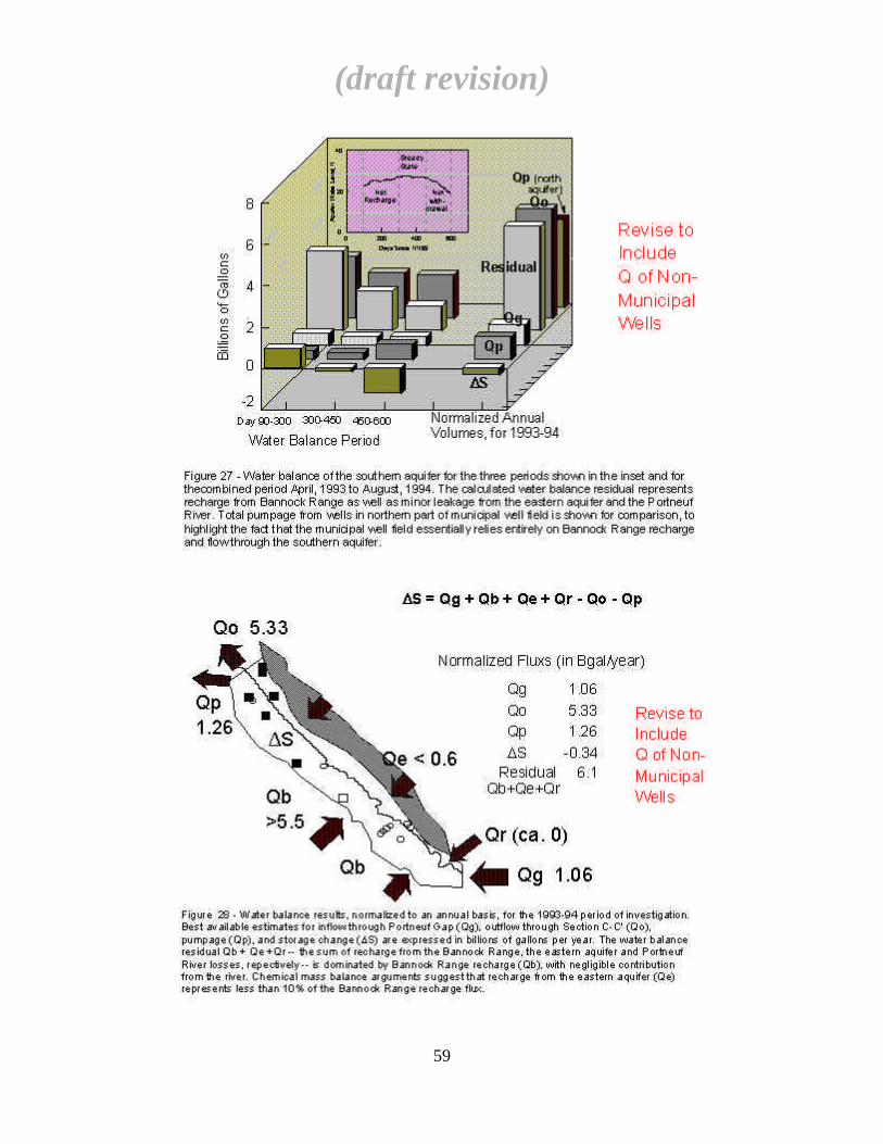
(draft revision)
59

When pumpage from wells in the north and central parts of the aquifer system is consideredtogether, the impact of pumping on the aquifer system is seen to be tremendous. For example, overthe entire 510-day period of the water balance, pumpage from north and central aquifer Pocatellomunicipal wells was 6.5 Bgal compared to 1.8 Bgal for the southern aquifer wells. Net storagedecline in the north and central aquifer is difficult to estimate with the available knowledge ofnorthern aquifer geology but appears to have been comparable to that in the southern aquifer (ca.0.1 vs. 0.5 Bgal, respectively). Since storage supplied less than 2% of the northern aquifer's wellproduction during this period, the remainder had to originate from tributary recharge inflow.Calculated total outflow from the southern aquifer, Qo, during the 510-day water balance periodwas 7.5 Bgal. Since most of this water probably recharged the uppermost aquifer of the northernsystem (cf. Figure 5) and since most of the northern wells are preferentially perforated in the upperaquifer, it is suggested that outflow from the southern aquifer supplies most, if not all, of thepumping withdrawal of the northern well field.
If the northern aquifer system receives only small amounts of recharge from sources other thansouthern aquifer outflow, the implications for maximum pumping capacity of the aquifer systemwill need to be examined. Total pumpage from all Pocatello wells in the northern and southernwell fields during the 510-day water balance accounting was 8.3 Bgal. In comparison, total knownrecharge to the system (Qg + residual) comprised 10 Bgal. Thus, essentially 85% of availablerecharge for that period was withdrawn through pumping and effectively consumed (except forstorm drain return which flows into the Portneuf River, all municipal waste water is discharged tothe municipal sewage treatment facility northwest of Chubbuck, well outside of the northernaquifer's boundary). This coincided with a net reduction in aquifer storage of approximately 0.6Bgal, most of which occurred in the southern aquifer. Because a complete accounting of thenorthern aquifer's water balance is not possible, it can only be speculated that the net storagedeficit is due to ground water outflow from the northern aquifer and that tributary inflows, such asfrom Pocatello Creek underflow, contribute only a small amount to the northern aquifer's waterbalance. If safe yield is defined as the annual extraction of ground water that does not exceedaverage annual recharge (Conkling, 1946), then the safe yield of the LPRV aquifer system may beclose to being realized under current pumping conditions and during the extended drought periodthat has existed for seven of the past eight years.
The calculated residuals during the latter two water balance periods average 3.0 Bgal per150-day period, or 2.7 x 106 ft3/day. This is approximately twice the flux calculated from apreliminary ground water flow model calibration performed for capture zone analysis in thesouthern aquifer, for the same time period (CH2M-Hill, 1994d). However, the flow model assumedrecharge only at the up-gradient end of the aquifer, and was calibrated only to hydraulic head datain a very limited area of the southern aquifer.
If river losses are indeed negligible during low-flow periods, then the relative proportion ofeastern aquifer recharge that may have contributed to the southern aquifer during 1994 may bediscernible on the basis of chemical mass balance. M.S. thesis work of C. Meehan is partlydevoted to determining whether independent estimates on recharge fluxes can be derived from
(draft revision)
60
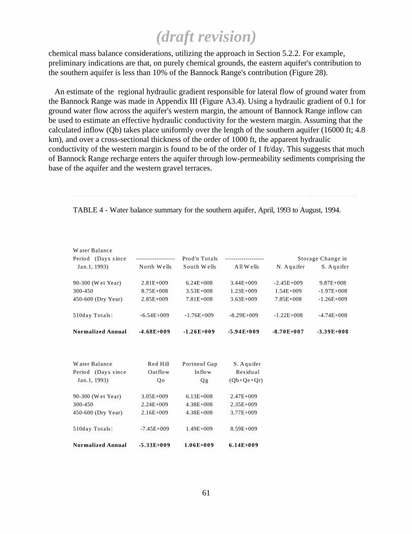
chemical mass balance considerations, utilizing the approach in Section 5.2.2. For example,preliminary indications are that, on purely chemical grounds, the eastern aquifer's contribution tothe southern aquifer is less than 10% of the Bannock Range's contribution (Figure 28).
An estimate of the regional hydraulic gradient responsible for lateral flow of ground water fromthe Bannock Range was made in Appendix III (Figure A3.4). Using a hydraulic gradient of 0.1 forground water flow across the aquifer's western margin, the amount of Bannock Range inflow canbe used to estimate an effective hydraulic conductivity for the western margin. Assuming that thecalculated inflow (Qb) takes place uniformly over the length of the southern aquifer (16000 ft; 4.8km), and over a cross-sectional thickness of the order of 1000 ft, the apparent hydraulicconductivity of the western margin is found to be of the order of 1 ft/day. This suggests that muchof Bannock Range recharge enters the aquifer through low-permeability sediments comprising thebase of the aquifer and the western gravel terraces.
(draft revision)
61
TABLE 4 - Water balance summary for the southern aquifer, April, 1993 to August, 1994.
W ater Balance
Period (Day s s ince ------------------- Prod 'n Totals ------------------- Storage Change in
Jan.1, 1993) North W e lls South W ells A ll W ells N. A q u ifer S. A q u ifer
90-300 (W et Year) 2.81E+009 6.24E+008 3.44E+009 -2.45E+009 9.87E+008
300-450 8.75E+008 3.53E+008 1.23E+009 1.54E+009 -1.97E+008
450-600 (Dry Year) 2.85E+009 7.81E+008 3.63E+009 7.85E+008 -1.26E+009
510day Totals : -6.54E+009 -1.76E+009 -8.29E+009 -1.22E+008 -4.74E+008
Normalized Annual -4 .68E+009 -1 .26E+009 -5 .94E+009 -8 .70E+007 -3 .39E+008
W ater Balance Red Hill Portneuf Gap S. A q u ifer
Period (Day s s ince Outflow In flow Res idual
Jan.1, 1993) Qo Qg (Qb+Qe+Qr)
90-300 (W et Year) 3.05E+009 6.13E+008 2.47E+009
300-450 2.24E+009 4.38E+008 2.35E+009
450-600 (Dry Year) 2.16E+009 4.38E+008 3.77E+009
510day Totals : -7.45E+009 1.49E+009 8.59E+009
Normalized Annual -5 .33E+009 1 .06E+009 6 .14E+009
7. WELLHEAD PROTECTION
7.1. OBJECTIVES
The objectives of the EPA-funded WHP Demonstration Grant study were 1) characterize thehydrogeology of the southern municipal aquifer; 2) define time-of-travel (TOT) zones for wellsthat could be compared with State of Idaho WHP guidelines (IDEQ, 1994); 3) identify alternativeapproaches to WHP capture zone delineation in similar aquifers; and 4) outline a methodology fordelineating refined WHP zones in municipal well fields utilizing commonly available municipalproduction well records. The first objective has been the focus of the preceding sections: that is,defining a working conceptual hydrogeologic model of the aquifer system that can form the basisfor quantitative modeling. The presentation and discussion of historic water level, specific capacityand chemical data in Sections 4 and 5, and the use of municipal production well water level data inSection 6.2, was intended to address the fourth objective: namely, the use of existing informationto provide reasonable, site-specific estimates of aquifer properties for capture zone modeling. Theapproach used in foregoing sections of this report can thus serve as a model for assembling andanalyzing such data in other municipal aquifer situations where water production records areavailable.
Objectives 2) and 3) constitute the focus of this section, namely, utilizing the informationobtained through aquifer characterization (or through the synthesis of existing records) to delineateWHP area(s) and a management strategy. Figure 29 defines basic WHP terminology used in thisreport (EPA, 1987). The simplest approach to implementation of a WHP plan is to define a zoneof contribution to individual pumping wells or to an entire well field (capture zone), where theextent of the zone is defined by the minimum time required for ground water (or a non-reactivecontaminant carried by the water) to move that distance (TOT zone). This zone, or a combinationof multiple zones for all wells in a well field, defines a WHP area within which contaminantsources and land use activities can be managed and controlled. The definition of this zone can beaccomplished by extremely simplistic means (arbitrary or calculated fixed radial zones) or morerefined techniques (simplified shapes; analytical, semi-analytical or numerical flow modeling).The most general and potentially most conservative approach to implementation of a WHP plan isto identify and map the boundaries of the system where recharge originates and within which aWHP area can be defined.
Because of the amount of geologic and hydrologic information that has been assembled, thesimplest approaches are considered inadequate to define realistic WHP areas. On the other hand,insufficient information about the nature of Bannock Range recharge is currently available tojustify development of a numerical flow model. Therefore, a 2-dimensional, semi-analyticalmodeling approach was initially chosen. However, the identification of possible diffuse rechargefrom the Bannock Range along the entire western margin (and possibly through the base of theaquifer, as well) has raised serious questions about the validity of 2-dimensional models in thissituation and how to assign and verify realistic boundary conditions to a 3-dimensional model.Because of these concerns, a reasonable alternative seems to be hydrogeologic mapping ofrecharge zones and system boundaries. These two alternatives are examined below.
(draft revision)
62
7.2. IMPLICATIONS OF THE AQUIFER MODEL FOR WHP
The southern LPRV aquifer is a narrow, relatively thin, strip aquifer, characterized by high linearflow velocity and high specific flux, and lateral impermeable or low-permeability boundarieswhich are relatively close to (within 1 km) all production wells. The influence of the PortneufRiver is minor and is assumed not to act as a significant recharge boundary. Lithologically, theaquifer appears to be unconfined but, over short pumping periods (several days), behaveshydraulically as a semi-confined system. This is interpreted to be because its lateral hydraulicconductivity is several orders of magnitude higher than its vertical hydraulic conductivity, leadingto delayed and relatively prolonged vertical drainage during pumping, and hence to the effectivelysemi-confined nature of the observed short-term well response.
These constraints naturally lend themselves to limiting the transverse spreading of flow lines,and hence of the capture zone, of a pumping well relative to axially-directed regional flow lines.The result is that capture zones should tend to be elongated in the direction of the valley axis, withthe degree of elongation increasing with horizontal hydraulic conductivity and regional flowvelocity.
On the other hand, the geometry of the southern aquifer (see cross-sections shown in Figures 6,7), observed storage changes and the results of water balance calculations create a more complexpicture. The principal source of aquifer recharge was determined to be from the Bannock Range,but the area of ingress of Bannock Range recharge may vary temporally along the aquifer's westernmargin. For example, during the spring, 1994 runoff period, most recharge appeared to originatefrom the Mink Creek/Gibson Jack drainages (cf. Figure 26). Later in the 1994 water year, relativeaquifer water level changes indicated that recharge from the Mink Creek area declined andappeared to enter the aquifer northwest of Mink Creek. Chemical survey data indicate thatBannock Range water also enters the aquifer through its base (cf. Figure 20).
These findings suggest that well capture zones in this aquifer are far more complex than thecommonly assumed, geometrically-simple shapes commonly associated with pumping wells in ahomogeneous aquifer characterized by uniform flow boundaries and recharge characteristics.Furthermore, because all of the southern production wells are close to the aquifer's margins, anyfluctuations in boundary input fluxes will have a proportionately greater effect on capture zoneshape.
7.3. CAPTURE ZONE MODELING
Because of the problems outlined in the preceding section, discrete capture zone modeling asoriginally conceived within the scope of this study (utilizing simple, 2-dimensional,semi-analytical models), has become less relevant to the definition of a meaningful WHP strategyfor the southern LPRV aquifer than alternative methods. Results of southern aquifer capture zoneand TOT modeling using this approach have been reported by Welhan and Meehan (1994).Capture zone modeling performed by CH2M-Hill (1994d) in the southern aquifer, utilizing2-dimensional numerical flow and particle-tracking models (MODFLOW and MODPATH), hasdemonstrated that capture zones are significantly narrower than those calculated via the
(draft revision)
63

semi-analytical approach. This difference is attributed to the use of variable aquifer thickness inthe CH2M-Hill model (in an attempt to incorporate 3-dimensional aquifer geometry) versus aconstant-thickness aquifer in the semi-analytical approach used by Welhan and Meehan (1994). Inthe MODFLOW model developed by CH2M-Hill, the aquifer was assumed to thicken inward fromits margins towards its axis, with the effect that flow lines were more constricted than in thesemi-analytical model which assumed a constant aquifer thickness.
However, since details of the semi-analytical approach utilized by Welhan and Meehan (1994)were not provided in that communication, and because the capture zones and TOT zones sodefined are useful in comparing WHP delineation methods, this sub-section describes themodeling approach used and summarizes the principal results.
The modeling software used in the semi-analytical approach was the GPTRAC option of theEPA's WHPA code (EPA, 1991). The semi-analytical option in GPTRAC was used, whereinpumping well capture and TOT zones in a homogeneous aquifer with simple, linear boundaries,are modeled by forward- or reverse-pathline analysis. Details of the model's assumptions,calculation algorithms and limitations are summarized in EPA (1991).
The model domain was chosen to cover the area influenced by municipal production wells 2, 3,13, 14, 28 and 36 (Figure 30). The Portneuf River was assumed not to act as a hydrologicboundary, and the model was run as a strip aquifer with two impermeable lateral boundaries. Theposition of the western boundary was fixed by the results of well 36's pumping test analysis, whichidentified the location of an impermeable barrier at a distance of ca. 600-800 feet (Figure 12;Section 4.1.2). The position of the eastern boundary was varied to simulate two scenarios: a) amaximum model width of 3000 ft (915 m), where the Portneuf Basalt and underlying sedimentsare assumed to define the eastern aquifer boundary; and b) a maximum model width of 6000 ft(1.83 km), where the sediments beneath the basalt do not impede lateral flow. The model was runin both unconfined and confined modes, with the radii of influence of all pumping wells set at2500 ft (762 m) for the unconfined case.
Aquifer thickness was set at either 65 ft (19.8 m) or 100 ft (30.5 m), to model the range ofvariations seen between wells east and west of the river at Section C-C' (see Figure 6b). Hydraulicconductivity was varied between 1000-5000 ft/d (305-1524 m/s). Effective porosity was set at 0.3,hydraulic gradient at 0.0015 and pumping rates were set at the maximum summer, 1994 values forindividual wells (1.5-5.8 ft3/s; 700-2600 gpm; 44-164 l/s). Well radii are taken from Table 1. Asummary of parameter values is given in Appendix IV.
Figure 31a shows the results of one model run, where the eastern boundary is defined by thewestern margin of the Portneuf Basalt and underlying sediments; Figure 31b shows the extent ofone-year TOT zones for identical conditions when the eastern boundary is moved 3000 feet (915m) east. In both model runs, aquifer thickness was maintained constant at 65 feet, and the effectsof pumping at wells 2 and 3 were described by a single pumping center located midway betweenthe two wells and pumping at their combined rate. The effect of nearby boundaries on capture zonegeometry is obvious in comparing the two figures. Note that in Figure 31b the capture zones of wells 2 and 3 extend beneath the basalt into the eastern aquifer. This provides an explanation for
(draft revision)
64
the high-chloride and nitrate values observed in Ross Park wells (Figures 16, 17): contaminatedeastern aquifer water is being drawn into these wells due to their high pumping rates. Such aninterpretation casts doubt on the supposition that the eastern margin of the southern aquifer isdefined by the edge of the Portneuf Basalt (CH2M-Hill, 1994d). It also suggests that leakage ofhigh-Cl and -SO4 water from the eastern aquifer may be occurring elsewhere along the margin ofthe basalt, giving rise to local, high-salt contents in southern aquifer water (Figure 20).
Figure 31c shows the extent of one-year TOT zones for conditions identical to Figures 31b,except that the model was run in unconfined aquifer mode. The differences between confined andunconfined responses under these conditions is minimal.
Figure 31d shows the tremendous difference that hydraulic conductivity makes in the geometryof capture zones. In this model run, only wells 13 and 36 are pumping and aquifer thickness is setat 100 feet (30.5 m). Note that the TOT zones shown are for 2-month travel times.
These model runs indicate that pumping wells in the southern aquifer are capable of interceptingup-gradient sources over essentially the entire width of the aquifer in those areas where aquiferhydraulic conductivity is near 1000 ft/d. Thus, the use of fixed-radius capture zones in a narrow,strip aquifer such as the southern aquifer of the LPRV could be an effective means of delineatinga WHP area which encompasses several pumping wells whose combined capture areas effectivelyspan the width of the strip aquifer. However, such a method may lead to considerableunder-estimation of the true capture zone area in cases where the boundaries of the aquifer areinadequately defined. Thus, in the case of Wells 2,3 and 28, the assumption that the PortneufBasalt and underlying sediments formed an effective barrier boundary (Figure 31a) for thehigh-permeability Upper Gravel aquifer leads to a serious misrepresentation of the actual wellcapture zones.
Under these conditions, two-year TOT zones are of the order of 2 miles (3.2 km) long. For thehigh-K range (5000 ft/d), capture zones are very narrow and elongated, and two-year TOTdistances of the order of 6 miles (10 km) result under these conditions. Welhan and Meehan's(1994) model runs included the extreme case of high-K (5000 ft/d) and low porosity (0.1), whichgive rise to even more elongated capture and TOT zones.
Comparison with numerically-modeled capture zones in which aquifer thickness can vary(CH2M-Hill, 1994d), shows that the analytical capture zone shapes are considerably wider for thesame hydraulic conductivity ranges used. Sensitivity runs with the GPTRAC model indicate thatthe modeled TOT distance is inversely proportional to the aquifer thickness assigned, all otherparameters remaining constant. This indicates that the extent to which the aquifer thicknessdeviates from a uniform slab of equivalent average thickness will determine how representativethe TOT distances determined from analytical modeling will be, compared to the actual TOTdistances. From what is known of the southern LPRV aquifer's basal geometry (eg: Appendix II), itis clear that analytically-defined TOT zones may be a poor representation of actual WHP areas.
Assuming that average aquifer hydraulic conductivity is closer to the low range used in thesecalculations, 5-year TOT zones for wells in the central aquifer and in the northern end of the
(draft revision)
65
southern aquifer will be manageable, since the WHP areas so defined would be confined withinthe boundaries of the aquifer. However, for wells south of PMW-1 and Well 14, or for longertravel times, calculated TOT zones will extend outside of the aquifer boundaries in a directiondependent on the locations of principal recharge inflow (Figure 32). For example, if the MinkCreek or Gibson Jack valley were the location of major recharge to the southern aquifer,semi-analytical methods would be hard-pressed to define WHP zones where flow diverged fromthe main aquifer and extended into complex boundary geology. Similarly, if diffuse recharge to thesouthern aquifer proved to be important along the western margin, then semi-analytical TOT zoneswould overestimate the travel distance in the up-gradient direction and WHP areas would be quitedifferent than those depicted here.
7.4. HYDROGEOLOGIC MAPPING AND RECHARGE ZONE DELINEATION
On the basis of our work on the water balance of the southern aquifer, it is clear that the southernaquifer's outflow is the source of much if not most of the northern aquifer's recharge. Therefore, bydefining and managing the southern aquifer's WHP areas, much will be accomplished in thenorthern area, as well. In the southern aquifer, it is possible to identify three principle rechargesource areas for WHP management. These are: a) the recharge areas in the Bannock Range that areresponsible for supplying high quality, pristine recharge to the aquifer system; b) recharge fromthe upper Portneuf River basin via the Portneuf Gap, whose quality is good but subject toup-gradient influences; and c) the area known as the eastern aquifer, which appears to be supplyinga relatively small quantity of water to the southern aquifer, but whose water quality is poor.
Of these areas, the Bannock Range/Mink Creek/Gibson Jack recharge zone is the most importantin terms of quantity and perhaps the easiest to manage from a WHP standpoint. It comprises awell-defined geographic area, of low population, low current land-use impacts and is potentiallythe most manageable area. Because of its low population, future growth and development can bemost easily controlled. A large part of this recharge zone is U.S. Forest Service-managed timberland, which provides excellent snowpack retention and moisture infiltration capability (unpubl.data). A hydrologic study of the Mink Creek watershed, which was begun in 1994, has provideddata on snowpack accumulation, recharge processes and sub-basin water balance which is in theprocess of being evaluated.
Evidence for leakage of contaminated water from the eastern aquifer has been documented inthis report and will be dealt with further in C. Meehan's M.S. thesis. This area is not denoted as arecharge zone per se for the LPRV although it does contribute recharge to the southern aquifer.Little is known of the source(s) of water or of solute in this subsystem, or of the relativeimportance of leakage from this aquifer into the southern aquifer during wet vs dry years.However, several factors including historically heavy land use in this area, the identification ofnumerous threats to ground water quality from industrial, small business and domestic sources(CH2M-Hill, 1994a), and the continuing potential for development in this area, will make it a difficult area to manage. From the WHP viewpoint, it is also unclear what the benefits ofmonitoring leakage from the eastern aquifer would be.
(draft revision)
66

The upper basin source area will undoubtedly be the most difficult recharge area to manage,because of its sheer size, the diversity of land uses in the upper basin, and the potential forconflicts with upper basin water users over water quantity and quality. However, its point ofimpact on the LPRV aquifer is also the most well-defined of the principle recharge sources, so thatmonitoring and management of the point of ingress will be perhaps the easiest.
(draft revision)
67

8. CONCLUSIONS
8.1. MAJOR FEATURES OF THE HYDROGEOLOGIC MODEL
The LPRV aquifer system is a unique ground water reservoir which is of critical importance tothe cities of Pocatello and Chubbuck. The aquifer system comprises two very differentsub-systems. The northern aquifer sub-system is several hundred feet deep, hydraulically confinedby two or more aquitards, and suffers from a variety of water quality problems. Unfortunately, thelack of subsurface information in this part of the system precludes an in-depth analysis of thenorthern system's hydrogeology. This is particularly frustrating because the northern aquifersystem is potentially of the greatest importance to future water resource development in the LPRVbecause of its tremendous storage potential.
The southern aquifer is a narrow, relatively shallow strip aquifer hosted in very permeable,coarse gravels, characterized by high linear flow velocities and suffering from serious TCEcontamination. This aquifer appears to be lithologically unconfined but shows hydraulicindications of semi-confinement. The mean hydraulic conductivity of all wells with test data in thesouthern aquifer is 2400 ft/d , with a range of 200-8200 ft/d. Based on estimates of hydraulicconductivity, hydraulic gradient and cross-sectional flow area, the southern aquifer's ground waterunderflow is estimated at 23ft3/s (5.3 Bgal/year). At an effective porosity of 0.3, ground water flowvelocity is of the order of 5 - 25 ft/day.
8.2. INORGANIC SALT CONTAMINATION
A third significant hydrogeologic system, the eastern aquifer, is not important as a municipalproduction source because of its small size and low permeability. However, it is contaminated withrelatively high concentrations of inorganic salts of chloride, sulfate and nitrate. Thesecontaminants have been appearing in Pocatello production wells in the Ross Park area for yearsand indicate that the eastern and southern aquifers are in hydraulic communication. Nitrate and saltcontamination is also present in the northern aquifer, apparently emanating from the mouth ofPocatello Creek. Localized salt contamination also exists around some private wells in thesouthern aquifer, indicating that contaminated surface water is communicating with the aquifer,probably along well casings that are improperly sealed.
8.3. AQUIFER WATER BALANCE
Ground water flow from the Bannock Range and the Portneuf Gap are the principal sources ofrecharge to the LPRV aquifer system, with Bannock Range sources representing about 30% of thetotal recharge during 1994 (a dry year) and more than 50% during 1993 (an above-average wateryear). Aside from these sources, there is no verified evidence of substantial river recharge, andalthough the eastern aquifer may contribute some recharge, on chemical grounds it appears thatleakage from the eastern aquifer represents less than 10% of the Bannock Range flux.
In terms of the magnitudes of water balance components, southern aquifer pumping needs werealmost completely met by the amount of ground water that flowed into the LPRV through the
(draft revision)
68

Portneuf Gap during 1993/94. Similarly, the northern well field relied on outflow from thesouthern aquifer for 80% of water withdrawn in the northern aquifer. Total well field pumpingwithdrawal during the 1993/94 water balance accounting period represented 90% of the totalknown recharge to the LPRV aquifer, suggesting that the aquifer system may be approaching itsmaximum safe yield during sustained drought conditions such as during the period 1986-1993.
(draft revision)
69

9. RECOMMENDATIONS
9.1. IMPLICATIONS FOR CONTAMINANT REMEDIATION
1) Bannock Range ground water inflow and Portneuf Gap underflow appear to be the mostimportant sources of recharge to the southern aquifer system, but contributions from the BannockRange may occur from diffuse inflow along the entire length of the southern aquifer's westernmargin as well as from localized areas such as near the mouths of Mink Creek and Gibson JackCreek. Pumping wells have been designed for TCE plume capture utilizing capture zonegeometries that are predicated on a single localized source of aquifer recharge originating from thePortneuf Gap. The effects of differences in the relative magnitude and location of ground waterinflow along the western valley margin should be considered and design contingencies developed.
2) The shape of TCE contaminant plume and ground water isopotential lines near the mouth ofMink Creek (as defined in the CH2M-Hill Phase I TCE plume study), as well as the water leveldata available for wells in the Gibson Jack-Mink Creek area for the Spring, 1993 recharge eventsuggests that this may be the location of the largest volume of inflow from Bannock Range sourcesduring spring recharge in normal water years. The impacts of this type of episodic, high-volumeinput on TCE plume capture should be investigated as one of the design contingencies in (1).
3) Capture zone modeling for Wells 2,3 and 28 suggests that chronically elevated levels ofdissolved salts and nitrate in Ross Park production wells may be due to the capture ofcontaminated ground water from the eastern aquifer, leaking into the southern aquifer under orthrough the Portneuf Basalt. Although knowledge of both the eastern aquifer's and the PortneufBasalt's geometry and geology is crucial to understanding the cross-communication between theeastern and southern aquifers, and in predicting the future water quality of production wellslocated near the Portneuf Basalt (eg: Ross Park wells, Katsilometes well), the subsurface geologyof this area is basically unknown. It is recommended that several of the gravity survey linescompleted across the southern aquifer in 1994 should be extended across the Portneuf Basalt andthe eastern aquifer in order to help define the subsurface geology of this area.
4) The deepest part of the LPRV's bedrock basin and the thickest section of Tertiary sedimentarybasin-fill exist in the area where Mink Creek enters the southern aquifer. This area is also whereleast is known of the TCE contaminant plume's geometry, source(s) and vertical distribution in theTertiary vs Upper Gravel sediments. TCE concentrations (CH2M-Hill, 1994d) in well PA-7, theonly well completed solely in Tertiary (or Pleistocene?) sediments, were as high as in wellscompleted in the Upper Gravel, suggesting that the Tertiary section here may be playing a role intransporting the contaminant. A deep test well (to at least 250 feet should be completed in theTertiary section, to permit hydraulic testing and determination of hydraulic parameters.
9.2. DELINEATION OF WHP AREAS AND WHP MANAGEMENT
1) Fixed-radius capture zones in a narrow, strip aquifer such as the southern aquifer of the LPRVshould be applied with caution, as the method may lead to under-estimation of the true capturezone area in cases where the boundaries of the aquifer are inadequately defined.
(draft revision)
70
2) The analytically-defined capture zones modeled for the southern LPRV aquifer are consideredto be very coarse approximations of true capture zone geometry because of the failure of simplifiedanalytical models' boundary conditions to adequately represent the actual boundary conditions.Effective delineation of capture and TOT zones should be accomplished with a numerical flow andparticle-tracking model.
3) Assuming that TOT zones calculated in this study underestimate travel distances because theassumed average aquifer thickness does not adequately represent the effective aquifer thickness,then actual TOT zones will be longer and may extend outside of the aquifer boundaries for manyof the southern aquifer's production wells. Conversely, if diffuse recharge to the southern aquiferproves to be important, then TOT zones modeled under the assumption of uniform axial flowwould overestimate the travel distance in the up-gradient direction and WHP areas would be toolong. In either case, the prospect for developing manageable and technically defensible WHP areasfor 5- and 10-year times of travel appears grim. It is recommended, therefore, that emphasis befocused on defining basin-wide WHP Recharge Zones defined by hydrogeologic boundaries.
4) The LPRV geohydrologic model indicates the existence of three principal areas of aquiferrecharge. Of these, the Bannock Range / Mink Creek Recharge Zone has the greatest potential fordevelopment of a workable, basin-wide WHP plan. The area is of manageable size, an historicprecedent exists in the exclusion of part of the City Creek drainage for water supply protection,and land-use management guidelines can be developed more readily in this mostly unpopulated,forested area than in populated areas. Furthermore, by developing a plan in cooperation with theU.S. Forest Service (who administers much of this watershed area), shared enforcement ofcontiguous lands may provide mutual benefits to the participating agencies.
5) The eastern aquifer represents a potentially important WHP Recharge Zone that should besingled early out for special monitoring. Leakage of contaminated waters into the southern aquiferis occurring in the Ross Park area and high concentrations of dissolved salts and nitrate in PMW-3(on the Idaho State University campus) indicate that contaminated eastern aquifer water may bemoving northwestward toward the central and southern well field. Because the hydraulics andinterconnection between the eastern and southern aquifer is unknown and because of thewidespread occurrence of existing and potential contaminants in this area (IDEQ, 1994;CH2M-Hill, 1994a) and the difficulty in developing a WHP plan in a heavily developed area,ground water monitoring is considered the only feasible approach to management in this WHParea, at least into the near future. The goal of monitoring would be to identify current and futureleakage and the types of contaminants, in order to be able to react effectively to future problemsand to obtain the necessary data to design a formal WHP plan for this area.
6) Ground water underflow through the Portneuf Gap originates from a huge recharge sourcearea (ie. the upper Portneuf River basin) that is probably unmanageable because of its geographicsize, the diversity of land uses within that area and the potential for political conflict betweenagricultural and urban water users. However, the Portneuf Gap is a highly manageable inflowzone, a geographically well-defined area through which all up-gradient flow passes. An area
(draft revision)
71
extending some 4.5 miles (7 km) up-gradient of the Portneuf Gap to the town of Inkom provides asignificant buffer zone between upper basin factors affecting up-gradient water quality and theimmediate jurisdictional boundaries of the LPRV aquifer. The corridor itself could be justifiablyincluded as part of the southern aquifer (because, geologically, its valley filling sedimentrepresents an eastward extension of the Upper Gravel aquifer), in which case, a formal WHP areathat extended into that area could be designated. Alternatively, it could be considered a bufferzone, only, in which case, the city could install and maintain up-gradient observation wells tomonitor the quality of upper basin water entering the LPRV which would provide early-warningcapability for developing water quality problems.
(draft revision)
72
10. REFERENCES
Bradbury, K.R. and Rothschild, E.R. 1985. A computerized technique for estimating the hydraulicconductivity of aquifers from specific capacity data; Ground Water, 23, pp. 240-246.
Brown and Caldwell 1994. Phase II Hydrogeologic assessment draft report, Bannock County,Idaho.
Burgel, W.D., Rodgers, D.W. and Link, P.K. (1987). Mesozoic and Cenozoic structures of thePocatello Region, Southeastern Idaho; in W.R. Miller (ed.), The Thrust Belt Revisited,Wyoming Geol. Assoc., 38th Field Conference Guidebook, pp. 91-100.
Bush, R.R. 1980. Gravity survey of the Tyhee area, Bannock Co., Idaho; M.S. thesis, IdahoState University, 33 pp.
CH2M-Hill 1994a. Contaminant source inventory and groundwater threat characterization report,City of Pocatello Well Head Demonstration Project, 57 pp..
CH2M-Hill 1994b. Final site assessment report, Pocatello Creek landfill hydrogeologicinvestigation, Pocatello, Idaho, 85 pp.
CH2M-Hill 1994c. Hydrogeology and assessment of TCE contamination in the southern portionof the Pocatello aquifer - Phase I Aquifer Managament Plan final report, 100 pp.
CH2M-Hill 1994d. Results of the test drilling program for the City of Chubbuck, Idaho - FinalReport, 26 pp.
Conkling, H. 1946. Utilization of groundwater storage in stream system development; Trans. Am.Soc. Civil Engrs., 111, pp. 275-305.
Corbett, M.K., Anderson, J.E. and Mitchell, J.C. 1980. An evaluation of thermal wateroccurrences in the Tyhee Area, Bannock County, Idaho; Idaho Department of WaterResources, Water Information Bulletin N. 30, Geothermal Investigations in Idaho, Part 10,67 pp.
Crosthwaite, E.G. 1957. Ground water possibilities south of the Snake River between Twin Fallsand Pocatello, ID; USGS Water Supply Paper 1460-C.
Environmental Protection Agency 1987. Guidelines for delineation of wellhead protection areas;Office of Ground-Water Protection.
Environmental Protection Agency 1991. WHPA: a modular semi-analytical model for thedelineation of wellhead protection areas, Version 2.0; Office of Ground-Water Protection.
Freeze, R.A. and Cherry, J.A. 1979. Groundwater; Prentice-Hall, New Jersey; 604 pp.Gat, J.R. 1971. Comments on the stable isotope method in regional groundwater investigations;
Water Resources Research, 7, pp. 980-990.Goldstein, F.J. 1981. Hydrogeology and water quality of Michaud Flats, Southeast Idaho; Idaho
State Univ., M.S. thesis, 80 pp.Harenberg, W.A., Jones, M.L., O'Dell, I., Brennan, T.S., Lehmann, A.K. and Tungate, A.M.
1993. Water resources data, Idaho, Water Year 1993; USGS Water Data Report ID-93-1.Houser, B. 1992. Quaternary stratigraphy of an area northeast of American Falls in the
eastern Snake River Plain; Geol. Soc. America Memmoir 179, pp. 269-288.IDEQ 1994. Idaho Wellhead Protection Plan, Draft, prepared for Idaho Dept. Health and
Welfare, Division of Environmental Quality in cooperation with the Idaho WHPWorkgroup.
IDEQ (in prep). Comprehensive review of groundwater contaminants impacting the lowerPortneuf aquifer, Pocatello, Idaho; Idaho Dept. Health and Welfare, Div. Environmental
(draft revision)
73
Quality, Southeastern Idaho Regional Office.Jacobsen, N.D. 1982. Ground water conditions in the eastern part of Michaud Flats, Fort Hall
Indian Reservation; USGS Open File Rept. 82-570, 35 pp.Jacobsen, N.D. 1984. Hydrogeology of eastern Michaud Flats, Fort Hall Indian Reservation;
USGS Water Resources Investigations Rept. 84-4201, 31 pp.Jasmer, R.M. 1987. Hydrocompaction hazards due to collapsible loess in Southeastern Idaho;
M.S. thesis, Idaho State University, 129 pp.Kindel, G. and others 1991. Geological and hydrogeological characterization of the Fort Hall
Canyon landfill site, Bannock County, Idaho; Proc., 27th Engineering Geology andGeological Engineering Symp., Logan, Utah, pp. 33-1 to 33-8.
LaPoint, P.J. 1977. Preliminary photogeological map of the eastern Snake River Plain; USGSMisc. Field Studies Map MF-850, 1:250000.
LeFebre, G.B. 1984. Geology of the Chinks Peak area, Pocatello Range, Bannock County, Idaho;Idaho State Univ., M.S. thesis, 61 pp.
Link, P.K., LeFebre, G.B, Pogue, K.R. and Burgel, W.D. (1985). Structural geology between thePutnam Thrust and tghe Snake River Plain, Southeastern Idaho; in Utah Geol. Assoc. Publ.14, Orogenic Patterns and Stratigraphy of North-Central Utah and southeastern Idaho, pp.97-117.
Ludlum, J.C. 1943. Structure and stratigraphy of part of the Bannock Range, Idaho; Geol. Soc.America Bull. 54.
Mansfield, G.R. 1920. Geography, geology and mineral resources of the Fort Hall IndianReservation; USGS Bull. 713.
McDole, R.E. 1969. Loess deposits adjacent to the Snake River Plain in the vicinity of Pocatello;Univ. Idaho, Ph.D. dissertation, 231 pp.
McDole, R. and others 1973. Identification of paleosols and the Fort Hall geosol in SoutheastIdaho loess deposits; Soil Sci. Soc. Am. 37, 611-616.
Meehan, C. and Welhan, J.A. 1994. Impact of leachable sulfate on the quality of groundwater inthe Pocatello aquifer; Proc. 30th Symp. Engineering Geology and GeotechnicalEngineering, Boise, ID; pp.19-35.
Muller, S.C. 1978. The geology and distribution of base-metal deposits in the Fort Hall miningdistrict, Bannock County, Idaho; M.S. thesis, Idaho State University, 194 pp.
Norvitch, R.F. and Larson, A.L. 1970. A reconnaissance of the water resources in the PortneufRiver Basin; Idaho Dept. Water Resources, Water Information Bull 16, 58pp.
O'Conner, 1990. Hydrology, hydraulics and sediment transport of Pleistocene Lake Bonnevilleflooding on the Snake River, Idaho; Ph.D. diss., Univ. Arizona, Tucson, 192 pp.
Ore, H.T. 1982. Tertiary and Quaternary evolution of the landscape in the Pocatello, Idaho, area;Northwest Geology 11, pp. 31-36.
Parliman, D.J. 1982. Ground water quality in east-central Idaho valleys; USGS Open File Rept.81-1011, 55pp.
Parliman, D.J. 1987. Hydrogeology and water quality of areas with persistent ground watercontamination near Blackfoot, Bingham County, Idaho; USGS Water Res. InvestigationsRept. 87-4150, 102 pp.
Pelton, J.R. , Dougherty, M.E. and Welhan, J.A. 1994. Interpretation of shallow seismicrefraction data using raytracing inversion: a simple example from a groundwater resourcestudy in Pocatello, Idaho; Proc. 30th Symp. Engineering Geology and Geotechnical
(draft revision)
74

Engineering, Boise, ID; pp.37-43.Reid, T.V., 1997, Gravity-defined subsurface paleomorphology and structure of the lower Portneuf
River valley, Pocatello, Idaho; M.S. thesis, Idaho State University, 72 pp.Reid, T.V., Welhan, J.A. and Pelton, J.R. 1995. Gravity-defined subsurface structure and
geometry of the lower Portneuf River Aquifer; Proc. 31th Symp. Engineering Geologyand Geotechnical Engineering, Logan, Utah; pp. 429-442.
Rember, W.C. and Bennett, E.H. 1979. Geologic map of the Pocatello quadrangle, Idaho; IdahoBur. Mines Geology, Geologic Map Series, Pocatello 2 deg quadrangle, 1:250000.
Rodgers, D.W., Ore, H.T. and Link, P.K. 1994. Geologic history of the Pocatello area; unpubl.manuscript, 12 pp.
Scott, W.E. 1982. Surficial geology map of the eastern Snake River Plain and adjacent areas;USGS Misc. Investigations Series. Map I - 1372.
Scott, W.E., Pierce, K.L., Bradbury, J.P. and Forester, R.M. 1982. Revised Quaternarystratigraphy and chronology in the American Falls Area, southeastern Idaho; in CenozoicGeology in Idaho, B. Bonnichsen and R.M. Breckenridge, eds., Idaho Bureau of Mines andGeology Bull. 26, pp. 581-595.
Seitz, H. and Norvitch, R. 1979. Ground water quality in Bannock, Bear Lake, Caribou and partof Power Counties, Southeast Idaho; USGS Water Resources Investigations 79-14, 51 pp.
Stearns, H.T. and others 1938. Geology and water resources in the Snake River Plain inSoutheast Idaho; USGS Water Supply Paper 774.
Trimble, D.E. 1976. Geology of the Michaud and Pocatello quadrangles; USGS Bull.1400, 88pp.University of Idaho, 1993, State of Idaho Mean Annual Precipitation, 1961-1990; U. Idaho, State
Climate Program, 1:250,000 GIS coverage.Walton, W.C. 1988. Groundwater pumping tests: design and analysis; Lewis Publ., Michigan,
201 pp.Welhan, J.A. and Meehan, C. 1994. Hydrogeology of the Pocatello aquifer: implications for
wellhead protection strategies; Proc. 30th Symp. Engineering Geology and GeotechnicalEngineering, Boise, ID; pp. 1-18.
West, S.W. and Kilburn, C. 1963. Ground water for irrigation in part of the Fort Hall IndianReservation; USGS Water Supply Paper 1576-D.
Winter, G., Baldwin, J., Wicherski, B. and Richlen, S. 1994. Black Cliffs ground water qualitystudy: nitrate impact; IDEQ Ground Water Quality Technical Report No. 4; 23 pp.
(draft revision)
75
APPENDIX I
Monitoring Well Logs
Wells Installed Under the EPA Well Head Protection and IWRRI Grants
A summary description of monitoring wells installed during August, 1993 is provided. Thesewells were funded jointly under the EPA Well Head Protection Demonstration Grant and aresearch grant awarded to the IGS and Idaho State University from the Idaho Water ResourcesResearch Institute. Costs for the drilling project are shared between the EPA WHP grant and .
All wells were drilled and completed by Cushman Pump and Drilling, Inc. under the directsupervision of the Idaho Geological Survey. Drilling was performed at three locations in thesouthern portion of the aquifer at a total cost of approximately $35/ft (for drilling, materials andinstallation, not including time donated by Welhan and student C. Meehan for well logging andcompletion). All three wells were drilled with direct air-rotary methods, utilizing an eccentric bitto over-ream the borehole for continuous casing advancement and for maintaining good controlon the depths of lithologic variations in the subsurface and obtaining clean, representativesamples of subsurface materials. Legal descriptions of well locations are attached below.
Well PMW-1 was sited to provide stratigraphic data, water level monitoring control and waterquality information in the vicinity of Wells #14 and 33, which were closed in 1993 due to TCEcontamination. Of the three wells drilled, this one has proved to be of greatest interest,geologically. The highly permeable, unconsolidated sedimentary aquifer from which producingwells 14 and 33 draw their water is now known to be less than 100 ft thick and underlain by asection of Tertiary sedimentary rocks which are much less permeable.
Well PMW-2 was sited 45 feet south of the city's new production well, #36, in order to afford ahydraulic monitoring point during testing of the new production well. In addition, the monitoringwell was used as a water quality sampling point to test the quality of water in Well 36, in order tosatisfy DEQ regulatory conditions for bringing well 36 on-line.
Monitoring well PMW-3 was drilled in the important "neck" of the aquifer, adjacent to Red Hill,to provide a check on the estimate of depth to bedrock obtained from geophysical seismicsounding performed in the spring of 1993, to identify the sedimentary stratigraphy and saturatedthickness available for aquifer underflow at that point, and to permit hydraulic testing and waterquality sampling to be done in this area of the aquifer.
Detailed descriptions of lithology and completion information is provided below, and a graphicalsummary of the monitoring wells' physical characteristics and lithology encountered is given inFigure A1.1.
Monitoring Well Locations - Legal Description:
PMW-1: T 7 S ; R 35 E ; Sec. 7 ; SW 1/4 of SE 1/4 sec. in Bannock County ; Pocatello City property; approximately 800 feet due north and 900 feet due east of the intersection of Cheyenne Ave. and Bannock Highway
PMW-2: T 7 S ; R 34 E ; Sec. 1 ; NW 1/4 of SE 1/4 sec. in Bannock County ; Pocatello City vacant property; approximately 400 feet due south of the intersection of Bannock Highway and South Grant Ave., approximately 100 feet due east of the highway.
PMW-3: T 6 S ; R 34 E ; Sec. 36 ; NW 1/4 of NW 1/4 sec. in Bannock County ; Idaho State University Campus; at east end of Sutter Street, between Mechanical Shop and Museum storage buildings
Materials Used in Well Completion:
330 ft of 4" ID PVC flush-thread riser pipe
60 ft of 4" ID `V-wire', 0.020"-slot, flush-thread PVC well screen
30 bags of 8/14 mesh Colorado silica sand
3 bags of 16/40 mesh Colorado silica sand
3 pails of 1/4" Baroid bentonite pellets

Lithologic and Well Completion Descriptions:
PMW-1 (depths referenced to top of steel casing, 28" above ground)0-10 ft:silt, clay (brown river floodplain sediment)10-20 ft: fine/med. gravel, silt-rich with abundant sand-size grains. 20-22 ft: pea gravel22-30 ft: coarse sand and boulders (slow drilling)30-35 ft: coarse sand35-40 ft: coarse, slightly silty gravel, first identified water ca. 38'40-70 ft: medium to coarse, slightly silty gravel68-75 ft: fine-grained partially indurated brown sand75-88 ft: silty fine sand and medium gravel, low permeability88-90 ft: clay seam90-100: some pea gravel but mostly gravel with sticky clay100-107: hard drilling in grey, homogeneous volcanic ash107-112: white, sticky clay; slow drilling112-121: brown, silty, medium gravel, hard drilling 121-140: very slow drilling in cemented gravel; clasts identical to cemented Tertiary
gravels exposed on Gibson Jack terrace
FINAL COMPLETION CONFIGURATION:
total depth = 140 ft btcpulled casing back to 80 ft btcbackfilled to 83 ft btc with cuttings and puddling claybackfilled to 87 ft btc with 8/14 mesh silica sand basebottom cap, 20 ft sump and screen installed, centralized 67 ftbottom of 0.020 v-wire screen at 67 ft btc; top at 57 ft btctop of 8/14 mesh sand pack at 47 ft btc total of 11 bags 8/14 sand, 1 bag 16/40 sand used60 ft of riser pipe installed, cut flush at top of casingriser pipe centralized at 47 ft btcafter sand packing, steel casing pulled backbottom of steel casing 42'2 1/2" blsbentonite pellets added to 25 ft btccement-bentonite grout pumped in from 25 ft btc to 4 ft btctop of PVC casing at 23" above groundtop of steel casing at 28" above ground

PMW-2 (depths referenced to top of steel casing, 24" above ground)0-23 ft:brown, moist river silt; cobbles hit at ca. 6 ft23-35 ft: med-coarse gravel, silty35-120: medium to coarse, clean gravel, very little silt. with several thin coarse
sand lenses at below about 45 ft. First water at identified ca. 49 ft. Waterflow rate increased gradually down to ca. 100 ft then remained very highand continuous
120-133: hard, slow drilling in coarse gravel and cobbles; largest clasts >5 cm 133-140: medium gravel, rapid drilling140-160: medium gravel, slow drilling
FINAL COMPLETION CONFIGURATION:
total depth = 160 ft btcpulled casing back to 120 ft btccap and 20 ft sump, centralized at 140 ft btcbottom of 0.020 v-wire screen at 140 ft btc, top at 120 ft.top of sand pack at 103 ft btc (8/14 mesh with 2 ft 16/40) total of 6 bags sand used (5 of8/14 mesh, 1 of 16/40 mesh)120 ft of riser pipe terminating 16" above groundriser pipe centralized at 110 ft btcafter sand packing, casing pulled back to 100 ft btcbottom of steel casing at 98.5 ft below ground surfacebentonite pellets added to 89 ft btcbentonite slurry injected from 89 to ca. 55 ft btcbentonite/cement grout injected from 55 ft to 4 ft btctop of PVC casing at 16" above groundtop of steel casing at 24" above ground
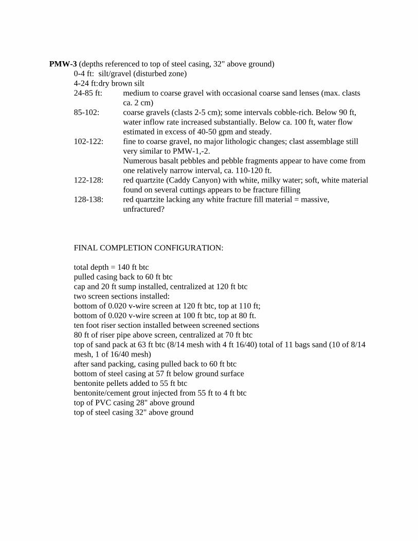
PMW-3 (depths referenced to top of steel casing, 32" above ground)0-4 ft: silt/gravel (disturbed zone)4-24 ft:dry brown silt24-85 ft: medium to coarse gravel with occasional coarse sand lenses (max. clasts
ca. 2 cm) 85-102: coarse gravels (clasts 2-5 cm); some intervals cobble-rich. Below 90 ft,
water inflow rate increased substantially. Below ca. 100 ft, water flowestimated in excess of 40-50 gpm and steady.
102-122: fine to coarse gravel, no major lithologic changes; clast assemblage stillvery similar to PMW-1,-2.Numerous basalt pebbles and pebble fragments appear to have come fromone relatively narrow interval, ca. 110-120 ft.
122-128: red quartzite (Caddy Canyon) with white, milky water; soft, white materialfound on several cuttings appears to be fracture filling
128-138: red quartzite lacking any white fracture fill material = massive,unfractured?
FINAL COMPLETION CONFIGURATION:
total depth = 140 ft btcpulled casing back to 60 ft btccap and 20 ft sump installed, centralized at 120 ft btctwo screen sections installed:bottom of 0.020 v-wire screen at 120 ft btc, top at 110 ft;bottom of 0.020 v-wire screen at 100 ft btc, top at 80 ft.ten foot riser section installed between screened sections80 ft of riser pipe above screen, centralized at 70 ft btctop of sand pack at 63 ft btc (8/14 mesh with 4 ft 16/40) total of 11 bags sand (10 of 8/14mesh, 1 of 16/40 mesh)after sand packing, casing pulled back to 60 ft btcbottom of steel casing at 57 ft below ground surfacebentonite pellets added to 55 ft btcbentonite/cement grout injected from 55 ft to 4 ft btctop of PVC casing 28" above groundtop of steel casing 32" above ground
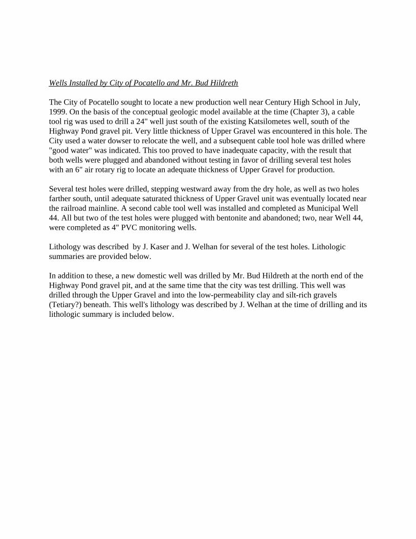
Wells Installed by City of Pocatello and Mr. Bud Hildreth
The City of Pocatello sought to locate a new production well near Century High School in July,1999. On the basis of the conceptual geologic model available at the time (Chapter 3), a cabletool rig was used to drill a 24" well just south of the existing Katsilometes well, south of theHighway Pond gravel pit. Very little thickness of Upper Gravel was encountered in this hole. TheCity used a water dowser to relocate the well, and a subsequent cable tool hole was drilled where"good water" was indicated. This too proved to have inadequate capacity, with the result thatboth wells were plugged and abandoned without testing in favor of drilling several test holeswith an 6" air rotary rig to locate an adequate thickness of Upper Gravel for production.
Several test holes were drilled, stepping westward away from the dry hole, as well as two holesfarther south, until adequate saturated thickness of Upper Gravel unit was eventually located nearthe railroad mainline. A second cable tool well was installed and completed as Municipal Well44. All but two of the test holes were plugged with bentonite and abandoned; two, near Well 44,were completed as 4" PVC monitoring wells.
Lithology was described by J. Kaser and J. Welhan for several of the test holes. Lithologicsummaries are provided below.
In addition to these, a new domestic well was drilled by Mr. Bud Hildreth at the north end of theHighway Pond gravel pit, and at the same time that the city was test drilling. This well wasdrilled through the Upper Gravel and into the low-permeability clay and silt-rich gravels(Tetiary?) beneath. This well's lithology was described by J. Welhan at the time of drilling and itslithologic summary is included below.
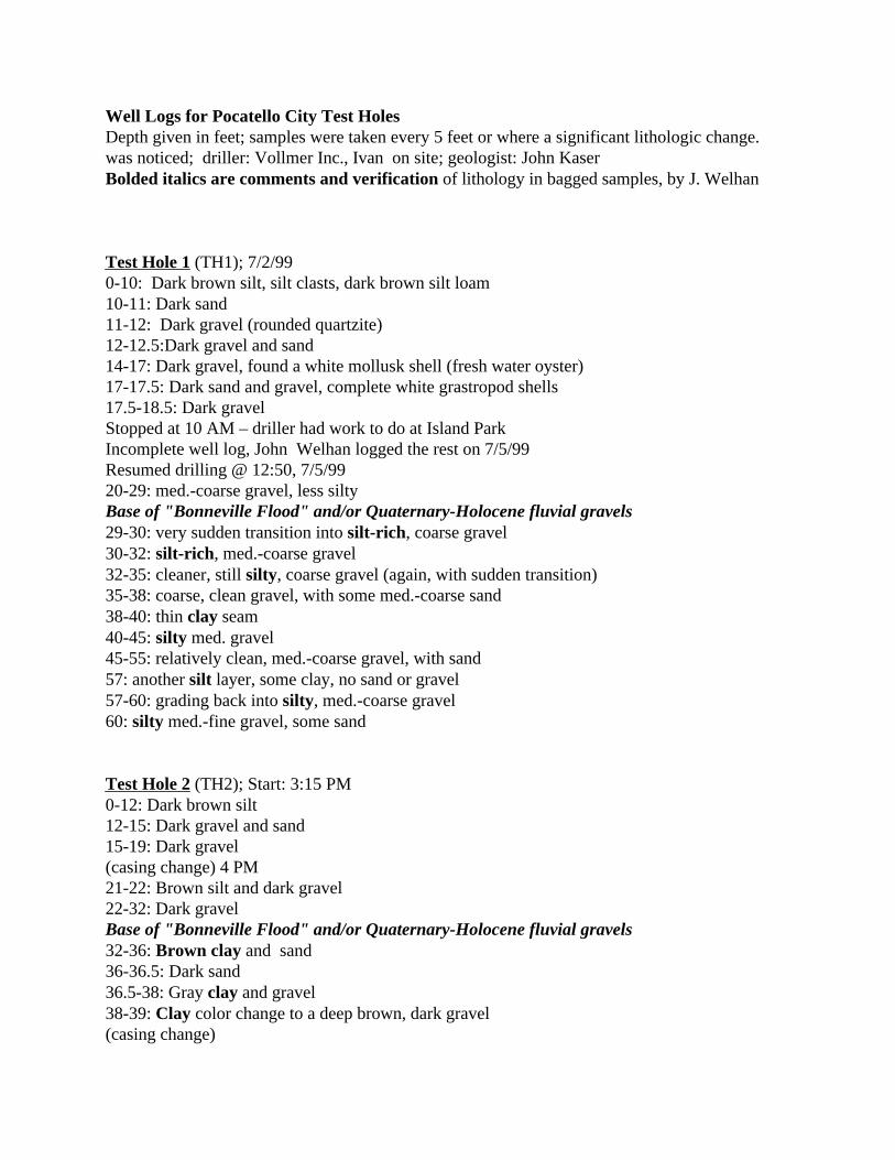
Well Logs for Pocatello City Test HolesDepth given in feet; samples were taken every 5 feet or where a significant lithologic change.was noticed; driller: Vollmer Inc., Ivan on site; geologist: John Kaser Bolded italics are comments and verification of lithology in bagged samples, by J. Welhan
Test Hole 1 (TH1); 7/2/990-10: Dark brown silt, silt clasts, dark brown silt loam10-11: Dark sand11-12: Dark gravel (rounded quartzite)12-12.5:Dark gravel and sand14-17: Dark gravel, found a white mollusk shell (fresh water oyster)17-17.5: Dark sand and gravel, complete white grastropod shells17.5-18.5: Dark gravelStopped at 10 AM – driller had work to do at Island ParkIncomplete well log, John Welhan logged the rest on 7/5/99Resumed drilling @ 12:50, 7/5/9920-29: med.-coarse gravel, less siltyBase of "Bonneville Flood" and/or Quaternary-Holocene fluvial gravels29-30: very sudden transition into silt-rich, coarse gravel30-32: silt-rich, med.-coarse gravel32-35: cleaner, still silty, coarse gravel (again, with sudden transition)35-38: coarse, clean gravel, with some med.-coarse sand38-40: thin clay seam40-45: silty med. gravel45-55: relatively clean, med.-coarse gravel, with sand57: another silt layer, some clay, no sand or gravel57-60: grading back into silty, med.-coarse gravel60: silty med.-fine gravel, some sand
Test Hole 2 (TH2); Start: 3:15 PM0-12: Dark brown silt12-15: Dark gravel and sand15-19: Dark gravel (casing change) 4 PM21-22: Brown silt and dark gravel22-32: Dark gravelBase of "Bonneville Flood" and/or Quaternary-Holocene fluvial gravels32-36: Brown clay and sand36-36.5: Dark sand36.5-38: Gray clay and gravel 38-39: Clay color change to a deep brown, dark gravel(casing change)

start: 4:57 PM NOTE: all gravel/coarse sand clasts look to be of similar39-40: sand, silty, clayey composition in all six test holes (mixed qtzite, meta-40-43: Dark sand and gravel, some brown clay sediments; colors: pink, purple, green, white)43-47: Brown clay and gravel layers47-49: Brown clay and dark gravel49-51: Brown clay 51-53: Dark gravel and brown clay53-55: Dark gravel and sand 55-56.5: Brown clay56.5-57: Dark gravel57-58: Dark sand with some gravel58-58.5: Mostly dark sand and some dark gravel(casing change) 5:45 PMstart: 6:04 PM59-59.5: Dark sand59.5-60: Dark gravel and sand – water encountered60-62: Brown clay. No water62-63: Dark sand63: Encountered an obstruction, probably a well-cemented conglomerate boulder. Cuttingscontain various rounded rock lithologies (i.e. gray mudstone, yellow quartz, red-brown quartzite)mixed with sand. The casing could not be hammered any further into the ground, past theobstruction.Stopped at 6:45
Test Hole 3 (TH3); 7/7/99; Start: 2:45 PM0-2: Dark brown topsoil2-5: Brown clay and dark gravel, white gastropod shells5-10: Dark gravel, some complete white gastropod shells10-13: Dark gravel and sand, white gastropod shells13-14: Mostly dark sand with some dark gravelNote: casing and drill moving easily, did not use hammer on casing until 13-15-ft14-18: Dark gravel and sand, white gastropod shells18-19: Dark gravel and sand(addition of 3-ft and 20-ft casing sections) 3 PM19-23: Dark gravel and sand, white gastropod shells23: Drill casing getting stuck, probably due to large rocks, hammer is used often23-25.5: Dark gravel, drill moving slowly through25.5: Brown clay, dark gravel and sand25.5-28: Mostly dark gravel with brown clay and some sand28-29: Brown clay with gravel and sand29-29.5: Brown clay29.5-30: Brown clay, gravel and sand30-31: conspicuous brown silt, some clay 31-33: brown clay and dark gravel

33-35: brown clay and dark sand35-38: brown clay with some dark sand38-38.5: brown clay (some clay chips found)38.5-39: dark sand with some dark gravel, sand is brown to dark red(casing change) 4:22 PMstart: 4:45 PMNote: casing is filled with water when starting39-41: brown clay, brown to dark red sand, and dark gravel41-43: gravel – pink and dark red quartzites or granite with black basalt or mudstone43-46: brown clay, pink to dark red sand and dark gravel46-49: brown silt/clay, dark sand and dark gravel, several thin layers of brown clay49-50.5: gravel50.5-51.5: brown clay and dark gravel51.5-52: dark gravel and dark sand52-53: brown clay, dark gravel and dark sand53-55: brown clay, dark sand and dark gravel55-57: brown clay, dark gravel and dark sand57-59: brown clay with minor amounts of dark sand(casing change) 5:30 PMStarted: 5:55 PMNote: casing filled with ground water59-62: brown clay, dark sand and dark gravel62-63: brown clay63-68: brown clay, dark gravel and dark sandNote: drill and casing is moving slower starting at 65-ftBase of "Bonneville Flood" and/or Quaternary-Holocene fluvial gravels69: Drilling halted due to obstruction. Hit a boulder or bedrock. Cuttings of the boulder orbedrock in the sample bag marked 'TH3, 7/7/99, Clay/gravel/sand, 68-69’Note: Ivan agreed to drill further in the morning, to obtain cuttings of the bedrock or boulderobstruction.Stopped: 6:25 PMContinued 7/7/99Start: 9 AM69-71: Sample taken of obstruction. Driller was able to drill through. Obstruction is not aboulder as previously thought, but possibly a layer of hardpan containing gravel and sticky clay,which is probably the same type of obstruction encountered for TH2. The driller, Ivan, put allthe weight of the truck onto the drill and hammered through the hard clay a gravel layer.71-72: dark gravel72-74: brown clay and dark gravel74-75: brown clay and sand with minor amounts of gravel75-77: pink gravel (pink to red quartzites, some gray and black slate or mudstone) and coarsesand77-79: Pink gravel and sandStopped to change casing 9:50 AM NOTE: Gravel from 75-100' looks clean, low silt/clayStart: 10 AM
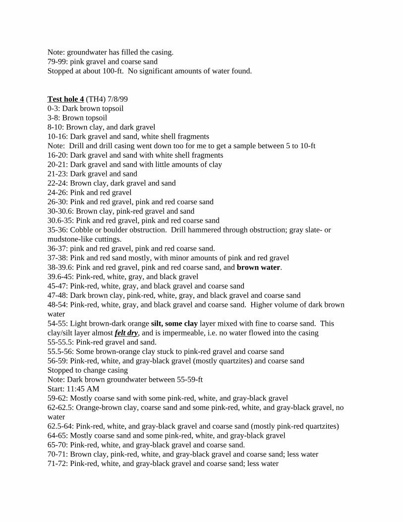
Note: groundwater has filled the casing.79-99: pink gravel and coarse sandStopped at about 100-ft. No significant amounts of water found.
Test hole 4 (TH4) 7/8/990-3: Dark brown topsoil3-8: Brown topsoil8-10: Brown clay, and dark gravel10-16: Dark gravel and sand, white shell fragmentsNote: Drill and drill casing went down too for me to get a sample between 5 to 10-ft16-20: Dark gravel and sand with white shell fragments20-21: Dark gravel and sand with little amounts of clay21-23: Dark gravel and sand22-24: Brown clay, dark gravel and sand24-26: Pink and red gravel26-30: Pink and red gravel, pink and red coarse sand30-30.6: Brown clay, pink-red gravel and sand30.6-35: Pink and red gravel, pink and red coarse sand35-36: Cobble or boulder obstruction. Drill hammered through obstruction; gray slate- ormudstone-like cuttings.36-37: pink and red gravel, pink and red coarse sand.37-38: Pink and red sand mostly, with minor amounts of pink and red gravel38-39.6: Pink and red gravel, pink and red coarse sand, and brown water. 39.6-45: Pink-red, white, gray, and black gravel45-47: Pink-red, white, gray, and black gravel and coarse sand47-48: Dark brown clay, pink-red, white, gray, and black gravel and coarse sand48-54: Pink-red, white, gray, and black gravel and coarse sand. Higher volume of dark brownwater54-55: Light brown-dark orange silt, some clay layer mixed with fine to coarse sand. Thisclay/silt layer almost felt dry, and is impermeable, i.e. no water flowed into the casing55-55.5: Pink-red gravel and sand.55.5-56: Some brown-orange clay stuck to pink-red gravel and coarse sand56-59: Pink-red, white, and gray-black gravel (mostly quartzites) and coarse sandStopped to change casingNote: Dark brown groundwater between 55-59-ftStart: 11:45 AM59-62: Mostly coarse sand with some pink-red, white, and gray-black gravel62-62.5: Orange-brown clay, coarse sand and some pink-red, white, and gray-black gravel, nowater62.5-64: Pink-red, white, and gray-black gravel and coarse sand (mostly pink-red quartzites)64-65: Mostly coarse sand and some pink-red, white, and gray-black gravel65-70: Pink-red, white, and gray-black gravel and coarse sand.70-71: Brown clay, pink-red, white, and gray-black gravel and coarse sand; less water71-72: Pink-red, white, and gray-black gravel and coarse sand; less water
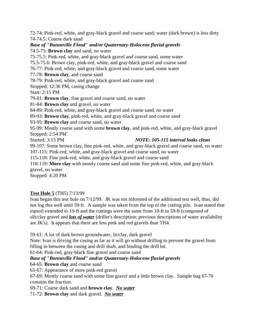
72-74: Pink-red, white, and gray-black gravel and coarse sand; water (dark brown) is less dirty74-74.5: Coarse dark sandBase of "Bonneville Flood" and/or Quaternary-Holocene fluvial gravels74.5-75: Brown clay and sand, no water75-75.5: Pink-red, white, and gray-black gravel and coarse sand, some water75.5-75.6: Brown clay, pink-red, white, and gray-black gravel and coarse sand76-77: Pink-red, white, and gray-black gravel and coarse sand, some water77-78: Brown clay, and coarse sand78-79: Pink-red, white, and gray-black gravel and coarse sandStopped; 12:36 PM, casing changeStart: 2:15 PM79-81: Brown clay, fine gravel and coarse sand, no water81-84: Brown clay and gravel, no water84-89: Pink-red, white, and gray-black gravel and coarse sand, no water89-93: Brown clay, pink-red, white, and gray-black gravel and coarse sand 93-95: Brown clay and coarse sand, no water95-99: Mostly coarse sand with some brown clay, and pink-red, white, and gray-black gravel Stopped: 2:54 PM`Started: 3:15 PM NOTE: 105-115 interval looks clean99-107: Some brown clay, fine pink-red, white, and gray-black gravel and coarse sand, no water107-115: Pink-red, white, and gray-black gravel and coarse sand, no water115-118: Fine pink-red, white, and gray-black gravel and coarse sand 118-119: More clay with mostly coarse sand and some fine pink-red, white, and gray-blackgravel, no waterStopped: 4:20 PM
Test Hole 5 (TH5) 7/13/99Ivan began this test hole on 7/12/99. JK was not informed of the additional test well, thus, didnot log this well until 59-ft. A sample was taken from the top of the cutting pile. Ivan stated thattopsoil extended to 10-ft and the cuttings were the same from 10-ft to 59-ft (composed ofsilt/clay gravel and lots of water (driller's description; previous descriptions of water availabilityare JK's). It appears that there are less pink and red gravels than TH4.
59-61: A lot of dark brown groundwater, lit/clay, dark gravelNote: Ivan is driving the casing as far as it will go without drilling to prevent the gravel fromfilling in between the casing and drill shaft, and binding the drill bit.61-64: Pink-red, gray-black fine gravel and coarse sandBase of "Bonneville Flood" and/or Quaternary-Holocene fluvial gravels64-65: Brown clay and coarse sand65-67: Appearance of more pink-red gravel67-69: Mostly coarse sand with some fine gravel and a little brown clay. Sample bag 67-70contains the fraction.69-71: Coarse dark sand and brown clay. No water71-72: Brown clay and dark gravel. No water

Stopped drilling at 72-ft., 10:30 AM
Test Hole 6 (TH6) 7/13/99; Start: 1:30 PM0-10: Dark brown topsoil10-12: Dark gravel12-16.5: Sand and brown clay, white shell fragments.Note: drilling is rapid to this point.16.5-17: Brown clay and dark gravelStopped ant 4 PM to add 3-ft and 20-ft casing extensions.17-18: Dark brown clay and dark gravel.18-19: Dark gravel. 19-23: Fine dark gravel and coarse sand.23-24: Water and rock debris spraying up from the outside of the casing due to reaching a water-bearing layer. Not much water. Cuttings are mostly coarse sand but appear to be chips fromgravel. Pink-red (quartzites), gray to black gravel (slate or mudstone), with some white gravel(quartz). 24-29: Dark gravel and sand. No water29-30: Dark gravel coarse to fine sand. Some water.30-40; Pink-red, gray-black, and white gravel.40-47: Mostly red-pink gravel and coarse sand. Little water.47-55: Mostly coarse sand and fine red-pink, black-gray, and some white gravel.55-65: Mostly coarse sand and fine red-pink, black-gray, and some white gravel, with somebrown clay.65-66: Mostly coarse sand and fine red-pink, black-gray, and some white gravel., with some hardbrown clay clasts.66-68: Mostly coarse sand and fine red-pink, black-gray, and some white gravel, and brown clay.68-69: Mostly fine red-pink, black-gray, and some white gravel, with some coarse sand.Base of "Bonneville Flood" and/or Quaternary-Holocene fluvial gravels69-70: Mostly coarse sand and fine red-pink, black-gray, and some white gravel, and brownclay.70-72: Mostly fine red-pink, black-gray, and some white gravel, with some coarse sand.72-74: Mostly coarse sand and fine red-pink, black-gray gravel with some white gravel, andbrown clay.74-76: Fine red-pink, black-gray, and some white gravel, with some coarse sand. Some brownclay and hard dark brown fine gravel clay balls.76-79: Red-pink, black-gray, and some white gravel, with some coarse sand. Little water. Stopped to change casing: 5 PMStart: 5:18 PM NOTE: 80-100 interval looks clean79-92: Red-pink, black-gray, and some white gravel, with some coarse sand. No water.92-98: Mostly coarse sand and fine red-pink, black-gray gravel with some white gravel.98-99: Red-pink, black-gray, and some white gravel, with some coarse sand, with a minor layerof brown clay.99-103: Red-pink, black-gray, and some white gravel, with some coarse sand and some brownclay.Stopped drilling at 6:30 PM

Bud Hildreth WellDrilled 7/21/99, Cushman Drilling Inc.; samples were collected by Monty Staples every 5 ft, asrequested; JW arrived when drill bit was at 165' bls; log reconstructed from examination ofbagged samples and Monty's description of lithology and zones encountered
1-7ft: silt, topsoil7-45: fine-med. sand and gravel NOTE: 10 bags bentonite used insealing casing-hole annulus45-55: med.-coarse sand and gravel Monty: water table at about 30' bls55-75: fine-med. sand and gravelBase of "Bonneville Flood" and/or Quaternary-Holocene fluvial gravels75: hard drilling, clay zone , possibly indurated NOTE: 10' discrepancy between bags
and Monty's notes, depth75-90: transition of contact is approximateHole stayed open below 90' overnight90-120: silt-rich, fine-med. sand and gravel NOTE: Monty encountered several
clay zones 90-145120-145: med.-coarse gravel, silt-rich 145-165: med.-coarse gravel with sand, much less silt and clay165-215: same, +/- silt NOTE: open hole 90-200' remained
open overnight

Estimates of Aquifer Permeability in Vicinity of City Test Well and Hildeth Well:
City Well 44Drawdown measurements were made on a test run of Well 44 to determine its capacity. Waterlevel was monitored in TH-5, 40 feet south of the production well. Flow sensor problemsprecluded an accurate measurement of discharge; Harold Hargraves indicated it was determinedafter the test to be in the range of 1600-1800 gpm.
Drawdown response fit a Neuman unconfined aquifer type curve, although the test wasinterrupted at 30 minutes by a temporary motor shutdown, so the amount of useable data is small.Two possible fits to the delayed-drainage portion and the late-time portion of the type curvesresulted in slightly more than a factor of two difference in the calculated transmissivity and a betafactor of 0.06 - 0.2. Average transmissivity was determined to be 33,408 ft2/day, with K = 742ft/day for a 45-ft saturated aquifer thickness.
Hildreth WellA crude water level recovery test was conducted on Hildreth's well after drilling stopped:6" ID casing, filled with drill pipe of 4.5" OD / 3.75"ID3:38:00 102.5' btc3:38:20 100.23:38:50 97.53:39:30 94.13:47:30 58.43:53:40 48.4Assuming that the formation head was in equilibrium with the removal of water from the bottomof the hole during drilling (by air flow), this recovery can be analyzed approximately as a slug-test (instantaneous release of slug = stoppage of air flow); using Hvorslev and Bouwer-Ricemethods, and an estimated ho value of 177' btc at to = 3:30, a good straight line semi-log slugrecovery response was obtained, with K = 4.46-4.96 x 10⁻⁴ ft/min (ca. 0.5 ft/day).
An accurate recovery test conducted on the well after it had been pumping continuously for 3days at 27 gpm corroborated the estimated permeability (0.7 ft/day). The actual drawdown duringthe pumping phase was much lower than predicted (35 ft vs. 100 ft), suggesting that the well-aquifer is behaving like a leaky system: the aquifer may be leaking or the well casing may notprovide an adequate seal.
Maurice Grady Well (Anecdotal information)100 ft TD, 12" casing, bottom of casing driven into clay zone; capacity was tested when drilled in
1961: 1900 gpm with 7 ft drawdown, static water level at 23 ft.

APPENDIX II
Results of the Pocatello Southern Aquifer 1994 Gravity Survey
A detailed gravity survey of the LPRV's southern aquifer was performed during 1994, undercontract funding from the City of Pocatello with additional surveying funded a funded extensionin 1995. The objective of this work was to extend the knowledge of subsurface geology over theentire area of the southern basin, utilizing existing well lithologic control to constrain the gravityinterpretation, and to better define the basal geometry of the southern aquifer and its boundaries.
The project was conceived on the basis of existing knowledge and hypotheses regarding theextent of the southern aquifer and tentative subsurface geologic interpretations (Welhan andMeehan, 1994). The scope of the work was designed to focus on providing a regional geologiccontext for existing lithologic data and to help interpret subsurface information from domesticwell logs in the comprehensive well database (Appendix III).
The gravity work comprises the bulk of the M.S. thesis research of T. Reid. The work includesheoretical design of survey lines, conducting precise elevation measurements at the locations ofgravity stations in traverses along the southern aquifer's axis and normal to the axis, acquisitionof gravity measurements at 234 individual stations, reduction of the raw data to final form andmodeling and geologic interpretation of the data. Since this work is part of T. Reid's M.S. thesis,it represents work in progress and only the final corrected data and preliminary interpretations arepresented here. Data collected recently under an IGS sub-contract sponsored by the U.S.Geological Survey as part of its Urban Mapping Program is included, with preliminaryinterpretations to provide constraints on depth of the northern aquifer system.
Plots of all southern aquifer gravity profiles are included below, together with a description ofmeasurement and interpretational methods used in the southern aquifer survey work. Copies ofpreliminary reports prepared by T. Reid detailing salient interpretational aspects of the southernaquifer data are attached as Appendices II-A and II-B. Preliminary data acquired form thenorthern aquifer and preliminary interpretations are presented as a preliminary report inAppendix II-C.
Methods
The strength of the earth's gravitational field, as measured at a point on the surface, is determinedby the thicknesses and densities of all the rock types beneath that point. The interpretation ofsuch a varied assortment of rocks in the subsurface from minute variations in the gravitationalfield would be impossible were it not for the fact that gravitational attraction induced bysubsurface masses decreases as the square of the separation distance between a rock mass atdepth and the surface. Thus, variations in gravity at the surface indicate the most about thedistribution of rocks of different densities nearer the surface than those at greater depths.Conversely, larger differences in density between rock types at greater depth can be observedmore readily than small density differences at shallow depth.
In practice, rather than the absolute value of the earth's gravitational field at a single point, it isthe variation of gravity from point to point at the surface which provides information on thedistribution of rocks in the subsurface. The interpretation of gravity data therefore depends onquantitative models to identify the various possible combinations of depth and density variationsthat can produce the observed gravity variations across the surface and on the availability ofsubsurface lithologic information to constrain the various possible combinations to those that areconsistent with known subsurface geology.
The physical nature of the Upper Gravel aquifer in the southern LPRV, comprised as it is ofporous gravels with a bulk density of ca. 2.0 g/cc (T. Reid and C. Meehan, unpubl. data), and theindurated nature and hence higher bulk density of much of the Tertiary Starlight Formation in thesouthern valley, suggests that density contrasts as low as 0.2 g/cc should be identifiable at depthsof up to 200 feet (61 m). The larger density contrast between sedimentary basin fill and bedrockshould be measurable over significantly larger depths.
In order to define and interpret variations in the depth of the top of Tertiary basin fill at minimumdepths of the order of 200 feet by means of gravity variations at the surface, the spacing betweenindividual gravity measurements should be no greater than the depth to the expected densitycontrast (Dobrin, 1960). In this case, the density contrast expected between the Upper Gravelsand the underlying indurated Tertiary sediments is assumed to be in the range of 0.2 - 0.3 g/cc.Variations in depth of this density contrast are expected to occur over relatively short distances,since the base of the Upper Gravel unit defines a pre-existing paleovalley topographic surfacewhose relief is likely comparable to the modern valley's. Hence, traverses across the aquifer'saxis are expected to provide the most information about this topography.
The larger density contrast between sedimentary basin fill and the underlying bedrock (0.4-0.5g/cc) would be expected to produce a less ambiguous interpretation of depth. However, the depthto this density contrast is expected to vary across the basin (D. Rodgers, pers. comm, 1993) fromabout a hundred feet in the area of Section B-B' and C-C' (Figure 6a, b) to several thousand feetin the central part of the Tertiery graben (in the vicinity of Section E-E'; Figure 7b). Thus,traverses along the axis of the valley, in which depth-to-bedrock is expected to vary the most, areexpected to provide the most information about bedrock structure. In order to define bedrock

depth variations of this magnitude, spacing between gravity stations need only be of the order of1000-1500 feet.
Figure A2.1 shows the locations of the gravity stations in the southern LPRV that were measuredduring 1994 and 1995. The 1994 stations were located primarily to provide detailed informationon subsurface variations in Tertiary topography and the depth of the Upper Gravel aquifer. The1995 stations were located for similar reasons as well as to define the nature of the bedrockprofile across the valley. The stations located along the southern axis also were used to tie thetransverse profiles to a common, local gravity datum.
All station locations were surveyed and tied to local bench marks to provide a high degree ofprecision in elevation positioning within an individual traverse of better than 0.1 foot.Northing-easting position control at each station was obtained from detailed, digitally-producedtopographic maps made available by the City of Pocatello that are based on the city's GIS(geographic information system) terrain database. These maps were constructed from anextremely detailed multi-base station Global Positioning System (GPS) survey (0.1 foot verticalaccuracy) and digital reduction of a dedicated, low-altitude aerial photographic survey. The mapshave two-foot contour spacing.
Elevation control was attained by careful surveying with a self-level-correcting digital theodoliteand an infrared Electronic Distance Measuring Instrument utilizing a triple mirror reflector. Thetechnique used was the trigonometric profile leveling method, wherein the slope distance ismeasured over a series of backsights and foresights, and elevation is calculated. After eachtraverse was laid out and gravity station locations were marked with stakes, instrument elevationwas determined from a backsight to a benchmark reference. A series of foresights was shot ateach station marker up to a distance of 600-1000 feet, with the slope distance and sight anglerecorded. The instrument was moved along the survey line, with a backsight shot on the lastforesight position. Closure to 0.1 foot elevation was accomplished by concluding the survey linewith a foresight to another benchmark. If the closure criterion was not met, the line wasre-surveyed until 0.1 foot closure was attained.
Measurements were made with a Worden Prospector gravity meter capable of resolvingvariations of the order of ten parts per billion in the strength of the earth's gavitational field asmeasured by the gravitational acceleration, g = 9.8 m/sec2 . This meter is designed around aquartz spring element designed to be self-compensating for thermal changes and is housed in ahermetically-sealed vacuum flask for further insulation against thermal and barometric pressurevariations.
On each gravity measurement traverse, an arbitrary base station was chosen at which readingswere made during the course of the day to determine meter drift and diurnal variations. Replicatereadings taken with the instrument at each station were corrected for instrument and diurnal drift;free-air elevation differences; local topography, using the method of Hammer (1939); andlatitude. All measurements are expressed in milligals, where a gal represents one percent of thegravitational acceleration constant, g, or 1 cm/sec2. The readings are considered significant to,

and are reported as, +_ 0.02 milligal. Thus, variations in g of the order of 1 part in 50 million areconsidered significant.
Results and Interpretation
Figure A2.2 provides a review of the final, corrected gravity data along the valley axis and alongeach of the profiles in Figure A2.1. As discussed in Appendix II-A and -B, the data indicate that,in those profiles in which subsurface geologic control is available, the gravity data are quiteconsistent with known geology and provide very important constraints on bedrock depth, aquiferboundaries and subsurface interconnection between aquifers.
The valley axis profile (Figure A2.2a) shows a much larger gravity anomaly (> 10 mgals) than isobserved in any of the transverse profiles; these variations are totally consistent with a structuralhalf-graben bedrock surface that plunges to more than 1500 feet below the surface. The apparentdepth-to-bedrock indicated by the gravity data decreases at both ends of the traverse, because ofthe bedrock high at the Red Hill end and because the axial traverse obliquely crosses thenorth-south trend of the graben axis, giving rise to shallowing bedrock as the basin-boundingfault is approached in the vicinity of the Portneuf Gap. Thus, in the area where the Tertiarypaleo-valley is known to be the shallowest (at monitoring well PMW-1, on the Indian Hillstraverse), the Tertiary sedimentary basin fill appears to be the thickest of anywhere in the entirevalley.
In Figure A2.2a, the Red Hill and Ross Park profiles were used to constrain the interpretation ofgeologic Sections B-B' and C-C'; the dashed lines in these figures indicate the relative variationof bedrock topography responsible for the observed gravity variations. Similarly, in FigureA2.2b, the sole location of lithologic control (PMW-1) fortuitously coincides with the gravityhigh, and indicates that the Tertiary paleovalley topography has more than 60 feet (18 m) of reliefat this locale.
The area with the most complete subsurface lithologic control for evaluating the effects ofTertiary paleo-topography on observed gravity is the Ball Park traverse (Figure A2.2c), wherefour wells intersected the Tertiary surface. As defined by drilling, the paleovalley here appears tobe nearly symmetrical, and this is supported by the gravity data, assuming a bulk density of theTertiary materials of 2.3 g/cc. In the vicinity of PA-7, the gravity data appears to deviate from thesymmetry dictated by the geometry of the Tertiary valley. Since PA-7 bottomed in several feet ofbasalt (CH2M-Hill, 1995) at a depth of 170 ft (CH2M-Hill, 1995), the local gravity anomaly atthis location indicates the presence of a fairly large body of basalt below 170 feet.
On the assumption that the underlying Tertiary topography at this location is a smoothly varyingsurface, the gravity anomaly beneath PA-7 can be explained by the presence of basalt body with across-sectional shape of ca. 100 ft thick by 1000 ft wide. This may represent either a field oflarge (ca. 100 ft diameter) boulders or an in-place lava flow. A small but sharp positive anomalyat ca. 2400 ft along the traverse (Figure A2.2c) is inconsistent with a basalt fragment at the baseof the Upper Gravel and, aside from a very large (> 5 x 5 ft) piece of iron buried a few feet belowthe surface, the only reasonable interpretation is that a large basalt boulder exists at mid-depth in

the Upper Gravel at this location. This, together with the interpretation of a very large basaltboulder field, provides evidence that the Upper Gravel post-dates the Bonneville flood, and thatthe flood was responsible for deeply scouring the southern valley and depositing a boulder fieldwhose maximum clast size ranged from ca. 100 feet in the scoured southern LPRV, to 10 feet inthe central aquifer area, to melon-size near American Falls reservoir.
In Figure A2.2d, two profiles are shown from the 1995 survey data. A third, the Fort Halltraverse, was chosen to coincide with seismic data generated by Brown and Caldwell's (1994)study of the Fort Hall alluvial fan area in which indurated Tertiary gravels were encountered indrilling and which may also have contributed to the observed seismic velocity profiles. However, since the gravity traverse crossed local bedrock structure at a high oblique angle, and nosubsurface lithologic control on bedrock depth was available, the gravity data yielded no usefulinformation.
The Portneuf Gap profile, shown in Figure A2.2d, indicates a simple V-shaped geometry of thesedimentary valley fill and indicates that the depth of sedimentray valley fill can be approximatedby extrapolating the valley walls into the subsurface (see Figure 25 in text) and that no unusuallydeep bedrock notch or fault gouge exists. The Riverside profile provides the clearest evidence yetobtained that the LPRV bedrock structure approximates a half-graben, down-dropped on the eastalong the range-bounding valley fault with a tilted western graben floor.
APPENDIX II-A
Paper presented at 31st Engineering Geology and Geotechnical Engineering Symposium
Logan, Utah
March 29-31, 1995
APPENDIX II-B
Results of the Pocatello Southern Aquifer 1995 Gravity Survey

APPENDIX II-C
Preliminary Results of the Pocatello Northern Aquifer 1996 Gravity Survey
Figure A2.3 shows locations of all gravity survey stations measured during the U.S. GeologicalSurvey-sponsored mapping of the Pocatello North quadrangle during 1996. Figure A2.4 showsthe magnitude of the gravity anomalies observed in the northern valley along the south-to-north(North Valley Axis) transect and the west-to-east (North Transverse) transect. In the NorthValley Axis profile, the 15 mgal anomaly is the largest observed in the entire study area.Preliminary modeling of this anomaly, assuming it is due only to a bedrock - sediment densitycontrast, indicates a sedimentary basin deepening from less than 200 feet over the Red Hillbedrock high to over 4000 feet beneath Chubbuck. If substantial basalt is intercalated within thesedimentary section, the maximum depth would be greater still.
The North Transverse profile also shows a substantial anomaly, indicating aneastward-deepening bedrock valley that is consistent with a half-graben structural basin asinferred from the Riverside profile in the southern aquifer (Figure A2.2d) but sloping much moresteeply to the east.
Although the nature of the basin-filling sediments in this deep structural trough remainconjectural, the results of the gravity profiling and modeling underscore the tremendous potentialof the northern aquifer system for future ground water development.

APPENDIX III
Aquifer System-Wide Well Database: Well Completion, Subsurface Lithology, Water Quality and Water Level Data
The creation of a regional hydrogeologic conceptual model of the current aquifer system hasbenefited enormously from the wealth of information available in the form of drillers' logs(municipal and domestic/irrigation wells), municipal records on aquifer water levels andproduction well pumpage, and water quality data on municipal production wells. Much of thisdata has been transcribed into digital spreadsheet and database form and has formed thecornerstone of the IGS' effort to develop a comprehensive understanding of the aquifer system.
Methods
The comprehensive well database was created from all available well logs in the southern andcentral aquifer and the surrounding areas. Because of the depth of the northern aquifer system,well logs that were included in the database were selected on the basis of depth and lithologicinformation. Since the northern aquifer system is much more complex geologically and deepdrilling has not been extensive, the subsurface information that is available for the northernsystem is necessarily much less complete than in the case of the southern aquifer. For this reason,most of the modelling and data interpretation effort has been focused on the southern aquifer andits well database. Figure 5 of the report was constructed on the basis of the lithologic informationavailable in the well database. Newly acquired data from Chubbuck deep test well drilling hasnot been incorporated into the database at the time of this writing (CH2M-Hill, 1995b).
Of the well logs that were available from the northern and southern/central areas, the welldatabase contains 202 entries that provide either lithologic or ground water level information. Ofthese, only 50 contain what is considered to be the best quality lithologic data; the remaininglithologic information from domestic, irrigation and industrial wells was considered to bepotentially useful but of unkown accuracy.
All available well reports have been compiled in hard copy form, and sorted by township, rangeand section. Information from the original well logs was transcribed and entered into two types ofdatabases: a well completion database (Table A3.1a,b), containing basic information on welllocation, collar elevation, depth, perforation (or screen) depth(s), water level at the time ofcompletion and specific capacity information; and a lithologic database (Table A3.2a,b), fromwhich information on the elevation of possibly correlative lithologic units can be extracted. Thelatter's information is admittedly subjective to the extent that an interpretation of the lithologicnature of the units described in individual drillers' reports was required prior to database entry,

and that this information was subject to re-examination and modification once the database wasanalyzed.
The lithologic data in Table A3.2 includes depths logged to "bedrock", the thickness of thesurface silt unit, and depths to the top (and bottom, if known) of various lithologic marker units,which were chosen tentatively on the basis of their potential to be consistently described by avariety of drillers and that could be potentially correlated to provide useful stratigraphicinformation.
Well locations and collar elevations were perhaps the most difficult pieces of supporting data toassemble. For wells whose location was known (eg: municipal wells, monitoring wells, identifieddomestic wells), spatial coordinates were obtained from detailed, 2-foot contour maps producedby the City of Pocatello (see Appendix II). The coordinate values given in Table A3.1a,b areconsidered accurate to within +_ 20 feet. These values are designated in the "Locating" column ofTables A3.1a and A3.1b as "GPS" entries. Those designated "SRV" represent X-Y valuesobtained in essentially the same manner, but were transcribed from the domestic well surveyinformation given in CH2M-Hill (1995). Finally, entries designated as "T&R" indicateapproximate coordinates for wells that were located on the basis of township, range, andquarter-quarter section, and converted to local coordinates using a conversion routine written byWelhan (unpubl.). In some cases, where wells could be located to the nearestquarter-quarter-quarter-quarter section, this conversion method places an absolute uncertainty onthe reported coordinates of +_ 170 feet.
Results and Discussion
In order to place the data from the subsurface into a regional perspective and to permit the use ofautomated surface analysis methods, a digital terrain model of the southern LPRV was created.This model was created at the IGS's Moscow CAD mapping laboratory, with detailedtopographic data obtained from the city's GIS database (Appendix II) and with contourinformation digitized from topographic maps. The GIS contour data was partially stripped toretain only 10-foot contour information from areas on the valley floor; 40-foot contours abovethe valley floor were digitized from USGS 7.5-minute quadrangle topographic maps. These datasets were then melded into a single file of elevation points. The points were then interpolated ona grid with 30 foot spacing and contoured with QuickSurf surface contouring software to producea 3-D surface that could be mated with other surfaces created from the well database. Acoarse-grid model derived from the full topographic surface model is shown in Figure A3.1.This model was created with a coarse grid of 200 foot spacing, simply to represent the features ofthe model. Even so, subtle features of the valley floor, such as the margin of the Portneuf Basaltand the Highway Ponds gravel pit are visible.
The lithologic database was intended to be used to construct a surface model of the regionalbedrock trends beneath and in the vicinity of the LPRV. As shown in Table A3.2a,b, the type ofbedrock logged by individual drillers is quite variable, but the entries are dominated by twodescriptions: "red rock" or quartzite, quite likely representing Proterozoic bedrock (forexampleWell 3, Section C-C'); and variously colored "shale", which may be true bedrock or an

inaccurate classification denoting a change to harder drilling conditions. Figure A3.2 shows acontour map of the elevation of this "bedrock" surface (together with locations of streams and thesouthern aquifer boundary for reference). Individual well locations that were used to constrainthe surface are also shown; additional elevation control was provided on the margins of thevalley with digitized bedrock outcrop elevations. This "bedrock" surface defines a fairlysymmetrical trough, distorted primarily by the Mink Creek/Gibson Jack drainage and the sharpbend taken by the Portneuf drainage through the Portneuf Gap at the lower right hand side of thefigure.
The most surprising feature of this map is the relatively shallow depth of "bedrock" beneath thefloor of the southern valley. As discussed in Appendix II, gravity data defines the thickness ofbasin fill beneath the southernmost part of the aquifer as in excess of 2000 feet, or more than 10times the depth to bedrock indicated in drillers' logs. As defined by gravity, the bedrock surfaceappears to drop sharply southeast of the bedrock high (at the northern end of the southernaquifer), and raches its maximum depth in the vicinity of Section E-E'.
Two cross-sections shown in Figure A3.2 were constructed to examine the types of "bedrock"found in different parts of the southern aquifer relative to the "bedrock" surface constructed fromall well data and the lithologies encountered in control wells whose accuracy is not in question.Figure A3.3a shows the longitudinal cross-section from the bedrock high at city Well 12 to thesouthernmost part of the aquifer, depicting the topographic surface (upper line) and the modelled"bedrock" surface (lower line) constrained by those wells that encountered "bedrock", as well asthe locations of control wells and their simplified lithology (heavy vertical lines indicate UpperGravel, solid and dotted horizontal lines indicate depths of true bedrock and Tertiary sediments,respectively).
The bedrock surface along this section undulates markedly due to the use of wells that are nearthe margin of the valley (where bedrock is at shallow depth; eg: Well 17) and others that arelocated closer to the center of the valley where bedrock would be expected to be deeper (eg:PMW-1). Of the wells shown in Figure A3.3a, 12, 36 and 17 are known to encounter true,Proterozoic quartzitic bedrock and thus are the only wells shown in this cross-section thatactually were used in constraining the "bedrock" surface shown. Southeast of Well 17, however,true bedrock has not been encountered in any control wells, and the "bedrock" surface there asdefined by domestic well drillers' logs must represent a lithologic discontinuity other than thechange from Upper Gravel to true bedrock.
Monitoring wells PMW-1 and PA-7 did not encounter bedrock and thus were not used toconstrain the modelled "bedrock" surface. However, PMW-1 encountered hard, cementedTertiary gravels at the depth indicated by the dotted line; PA-7 encountered a transitional, siltygravel immediately prior to terminating in basalt. As discussed in Appendix II and Section 3.2.4,this basalt appears to represent a ca. 100 ft-thick boulder field or lava flow which is inferred torest on the floor of the paleovalley incised in Tertiary sediments. At both locations, the depth ofthe Tertiary material is within 75 feet of the "bedrock" surface defined on the basis of other wellsin the vicinity in which drillers encountered drilling conditions and/or lithologies that were"bedrock-like". The deep Forsman (Pein) well was one of the 25% of the non-municipal wells in
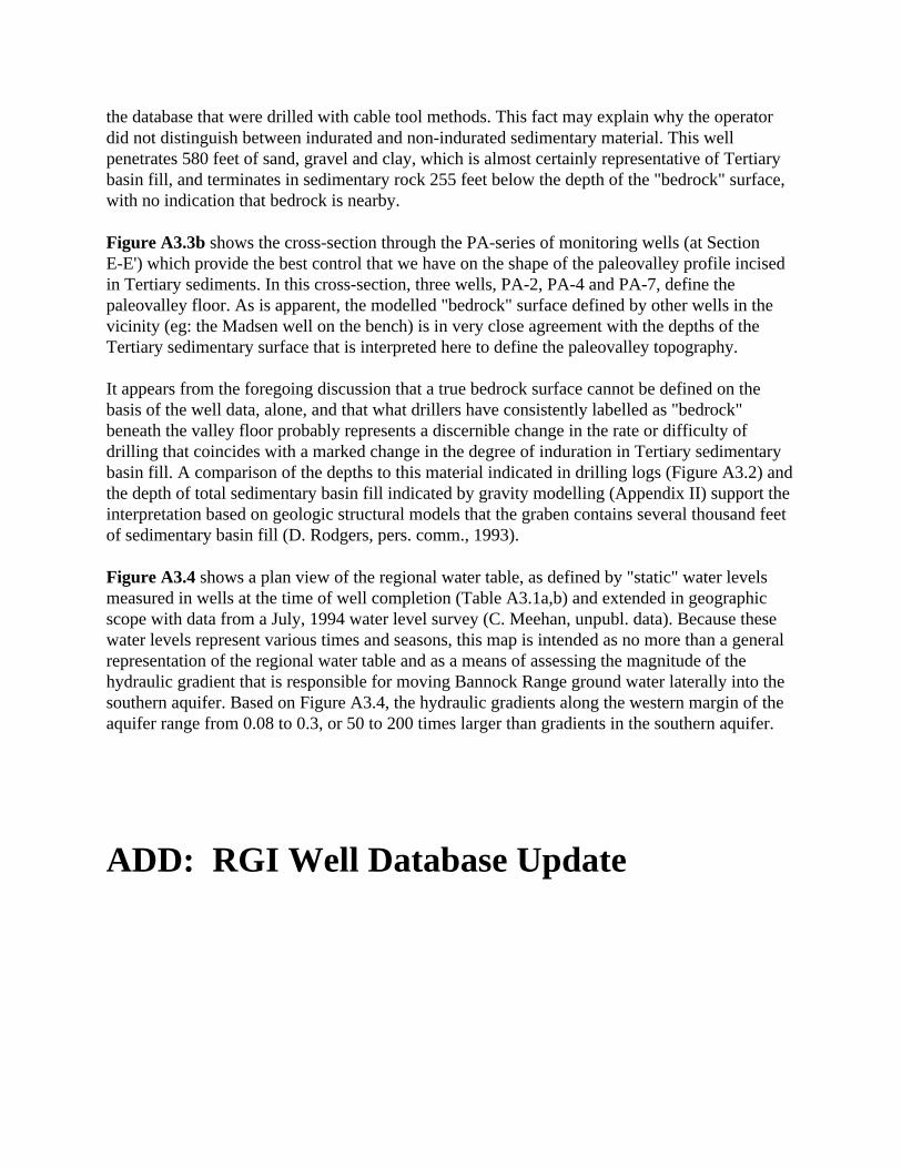
the database that were drilled with cable tool methods. This fact may explain why the operatordid not distinguish between indurated and non-indurated sedimentary material. This wellpenetrates 580 feet of sand, gravel and clay, which is almost certainly representative of Tertiarybasin fill, and terminates in sedimentary rock 255 feet below the depth of the "bedrock" surface,with no indication that bedrock is nearby.
Figure A3.3b shows the cross-section through the PA-series of monitoring wells (at SectionE-E') which provide the best control that we have on the shape of the paleovalley profile incisedin Tertiary sediments. In this cross-section, three wells, PA-2, PA-4 and PA-7, define thepaleovalley floor. As is apparent, the modelled "bedrock" surface defined by other wells in thevicinity (eg: the Madsen well on the bench) is in very close agreement with the depths of theTertiary sedimentary surface that is interpreted here to define the paleovalley topography.
It appears from the foregoing discussion that a true bedrock surface cannot be defined on thebasis of the well data, alone, and that what drillers have consistently labelled as "bedrock"beneath the valley floor probably represents a discernible change in the rate or difficulty ofdrilling that coincides with a marked change in the degree of induration in Tertiary sedimentarybasin fill. A comparison of the depths to this material indicated in drilling logs (Figure A3.2) andthe depth of total sedimentary basin fill indicated by gravity modelling (Appendix II) support theinterpretation based on geologic structural models that the graben contains several thousand feetof sedimentary basin fill (D. Rodgers, pers. comm., 1993).
Figure A3.4 shows a plan view of the regional water table, as defined by "static" water levelsmeasured in wells at the time of well completion (Table A3.1a,b) and extended in geographicscope with data from a July, 1994 water level survey (C. Meehan, unpubl. data). Because thesewater levels represent various times and seasons, this map is intended as no more than a generalrepresentation of the regional water table and as a means of assessing the magnitude of thehydraulic gradient that is responsible for moving Bannock Range ground water laterally into thesouthern aquifer. Based on Figure A3.4, the hydraulic gradients along the western margin of theaquifer range from 0.08 to 0.3, or 50 to 200 times larger than gradients in the southern aquifer.
ADD: RGI Well Database Update

APPENDIX IV
Table A4.1 - WHP Area Modeling Conditions Used in GPTRAC
Units: feet, days
Grid area:x = 0-1800 (for river boundary only)y = 0-3000 (for southern aquifer)x = 0-6000 (for eastern aquifer)y = 0-8000
Maximum step length = 300
Transmissivity:Well 36 = 500,000 ft2/d (Kh = 5000 ft/d)Well 2, 3, 28, 13 = 85,000 ft2/d (Kh = 1000 ft/d)
For semi-confined cases: Kv' = 1 ft/day, b' = 50 ft
For unconfined cases: set radii of influence at 2500 feet
Aquifer properties:b = 100 feetn = 0.30i = 0.0015theta = 90 degrees
Times of travel: for low-T cases, use 365 days; for high-T cases, use 60 days
Well coordinates: Discharge (gpm, max. daily 1994 values):Well 36 x = 800 y = 7040 Q = 1400 gpmWell 13 x = 800 y = 4720 Q = 1200Well 2+3 x = 2740 y = 7900 Q = 2600 (combined)Well 28 x = 2400 y = 5440 Q = 700
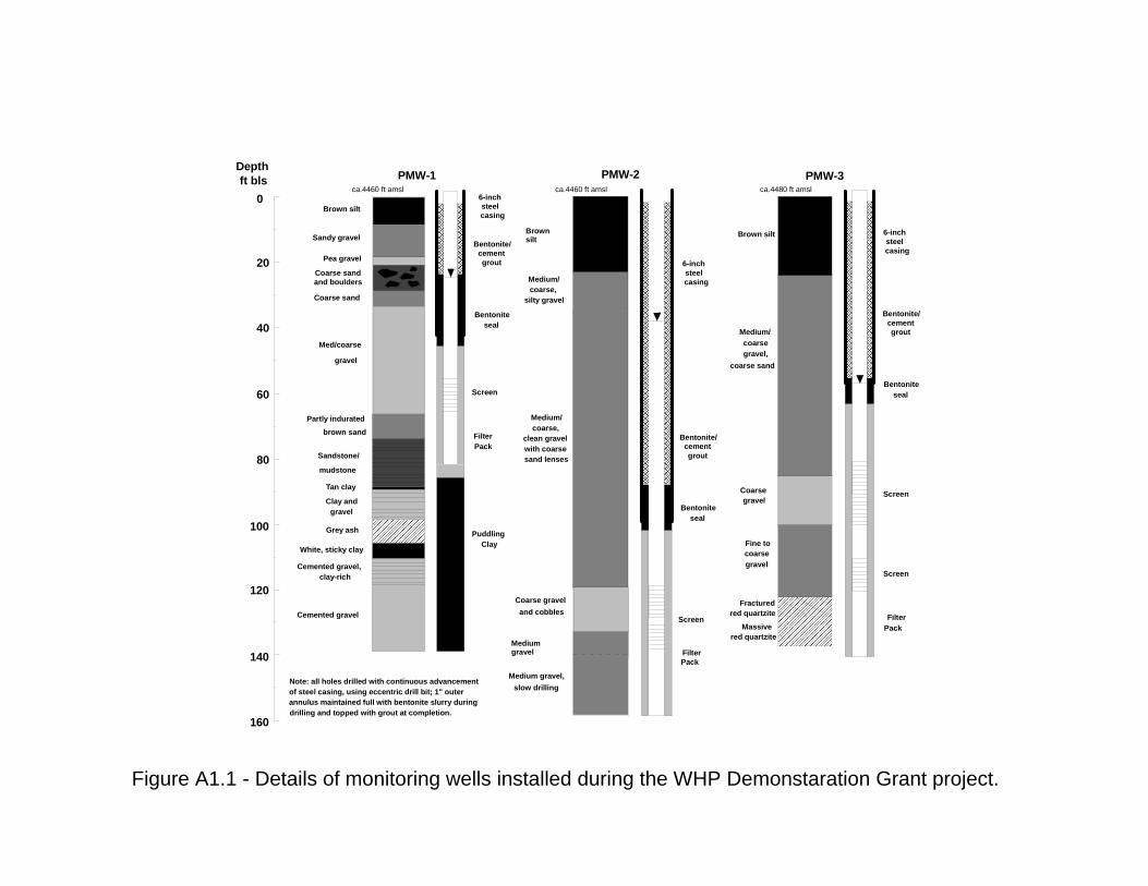
Figure A1.1 - Details of monitoring wells installed during the WHP Demonstaration Grant project.
0
20
40
60
80
100
120
140
160
ft blsDepth
PMW-1 PMW-2 PMW-3
Tan clay
Sandstone/
mudstone
Partly indurated
brown sand
Med/coarse
gravel
Coarse sand
Coarse sandand boulders
Pea gravel
Sandy gravel
Brown silt
Clay andgravel
Grey ash
White, sticky clay
Cemented gravel,
Cemented gravel
clay-rich
Brown silt
Medium/coarse,
silty gravel
Medium/coarse,
clean gravelwith coarsesand lenses
Coarse graveland cobbles
Medium gravel
Medium gravel,slow drilling
ca.4460 ft amsl ca.4460 ft amsl
Brown silt
Medium/coarsegravel,
coarse sand
Coarsegravel
Fine tocoarsegravel
Fracturedred quartzite
Massivered quartzite
ca.4480 ft amsl
PuddlingClay
Filter Pack
Bentoniteseal
Bentonite/cementgrout
Pack
Bentoniteseal
Bentonite/cementgrout
Pack
Bentoniteseal
Bentonite/cementgrout
Screen
Screen
Screen
Screen
Note: all holes drilled with continuous advancement of steel casing, using eccentric drill bit; 1" outerannulus maintained full with bentonite slurry duringdrilling and topped with grout at completion.
Filter
Filter
6-inchsteelcasing
6-inchsteelcasing
6-inchsteelcasing

Figure A2.1 - Locations of stations in the microgravity survey of the southern aquifer (circles 1994; diamonds 1995). Names identify traverses and profiles that are presented in succeeding figures. Also shown are locations of some of the municipal and monitoring wells (filled diamonds) that provided lithologic control in gravity-based model interpretations of subsurface geology.
POCATELLOCREEK
MIN
K
CREEK
Red Hill
Ross Park
Indian Hills
Country ClubBall Park
Mink Creek
Riverside
Fort HallPortneuf Gap
1 MILE

Figure A2.2a - Bouguer gravity profiles, in mgals, for the longitudinal valley axis profile (1) and transverse profiles at Red Hill (2) and Ross Park (3). Dotted arrows indicate projections onto the plane of the profile. Inferred trends in bedrock topography are indicated by dashed lines.
0 5 10 15 20 25
344
346
348
350
352
354
0 1000 2000 3000 feet349
350
351
352
Ross Park
0 1000 2000 3000 4000 5000 feet351
352
353
354
Red Hill
Red Hill Ross
Park
Well 36
Well 3PMW-3
Well 7Well 12
Thousands of Feet
milli
gals
milli
gals
West EastWest East
South Valley Axis, North -> South1
2 3

Figure A2.2b - The Indian Hills Bouguer gravity anomaly at test well PMW-1 (2) suggests that the Upper Gravel aquifer at that location is thinner; Tertiary sediments were encountered in PMW-1 at their highest elevation beneath the valley floor (see lithologic log). Since neither gravity profile (2) or (3) is influenced by near-surface bedrock, these microgravity variations reflect the subtle density contrast (2.0 vs. 2.55 g/cm3 ) between the Upper Gravels and underlying, partly-indurated Tertiary sediments, and can be used to model the base of the Upper Gravel aquifer.
344
346
348
350
352
354
Thousands of Feet
South Valley Axis, North -> South
Indian Hills Country
Club
0 1000 2000 3000 feet344
345
346
347
Indian Hills
0 1000 2000 3000 4000 feet343
344
345
346
Country Club
0 5 10 15 20 25
PMW-1
mill
igal
s
mill
igal
s
West EastWest East
1
2 3
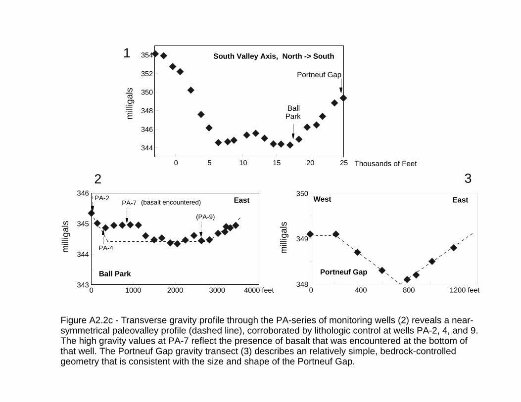
Figure A2.2c - Transverse gravity profile through the PA-series of monitoring wells (2) reveals a near- symmetrical paleovalley profile (dashed line), corroborated by lithologic control at wells PA-2, 4, and 9. The high gravity values at PA-7 reflect the presence of basalt that was encountered at the bottom of that well. The Portneuf Gap gravity transect (3) describes an relatively simple, bedrock-controlled geometry that is consistent with the size and shape of the Portneuf Gap.
0 1000 2000 3000 4000 feet343
344
345
346
Ball Park
344
346
348
350
352
354
Thousands of Feet
BallPark
0 5 10 15 20 25
PA-2
PA-4
PA-7
(PA-9)
(basalt encountered)
mill
igal
s
mill
igal
s
East
South Valley Axis, North -> South
0 400 800 1200 feet348
349
350
Portneuf Gapm
illig
als
West East
Portneuf Gap
1
2 3
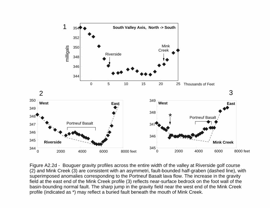
0 2000 4000 6000 8000 feet344
345
346
347
348
349
350
Riverside
Portneuf Basalt
West East
0 5 10 15 20 25
344
346
348
350
352
354
Riverside
Thousands of Feet
Figure A2.2d - Bouguer gravity profiles across the entire width of the valley at Riverside golf course (2) and Mink Creek (3) are consistent with an asymmetri, fault-bounded half-graben (dashed line), with superimposed anomalies corresponding to the Portneuf Basalt lava flow. The increase in the gravity field at the east end of the Mink Creek profile (3) reflects near-surface bedrock on the foot wall of the basin-bounding normal fault. The sharp jump in the gravity field near the west end of the Mink Creek profile (indicated as *) may reflect a buried fault beneath the mouth of Mink Creek.
milli
gals
South Valley Axis, North -> South
0 2000 4000 6000 8000 feet345
346
347
348
349
Mink Creek
West East
Portneuf Basalt
MinkCreek
1
2 3
*
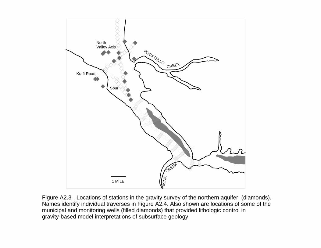
1 MILE
Figure A2.3 - Locations of stations in the gravity survey of the northern aquifer (diamonds). Names identify individual traverses in Figure A2.4. Also shown are locations of some of the municipal and monitoring wells (filled diamonds) that provided lithologic control in gravity-based model interpretations of subsurface geology.
POCATELLOCREEK
MIN
KCREEK
North Valley Axis
Kraft Road
Spur

Figure A2.4 - Bouguer gravity profile along North Valley Axis (1) and Kraft road traverses (2), showing decreases of 10-15 mgal to the north and east. The magnitude of the variation indicates that depth to bedrock beneath Chubbuck is greater than 4000 feet. The Kraft Road profile also is consistent with a half-graben bedrock valley geometry.
0 5000 10000 15000 20000 25000 30000 feet
320
325
330
335
340
milli
gals
Kraft Road
North Valley Axis, South -> North
Kraft Road
0 5000 10000 15000 20000 feet320
325
330
335
340
West East
mill
igal
s
1 2

RELATIVE BOUGUER ANOMALY AND MODEL FOR RED HILL PROFILE
0
mgals
-1
0
feet
190width = 5000 feet vertical exaggeration = 3.5
W E
Valley AxisProfile
Unconsolidated gravel2.0 g/cm 3
Bedrock2.55 g/cm 3
95 ft138 ft 107 ft
Well 30a Well 12 Well 3 4459 ft amsl
?
?
Figure A2.5a - Modeled geologic profile along the Red Hill traverse, based on assumed rock densities and available well control. Reference elevation for the 2D model is given at the upper right corner of the model (4450 ft amsl). The gap in gravity data in the left-center of the traverse is wide enough to accomodate a bedrock notch with a range of geometries (width: 300- 600 ft; depth: 350-200 ft, respectively), whose existence is consistent with, and possibly controls, contaminant plume behavior.
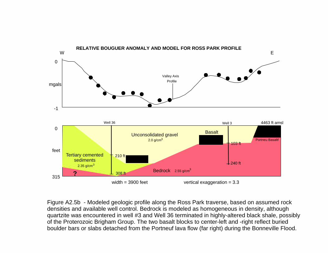
0
mgals
-1
0
feet
315width = 3900 feet vertical exaggeration = 3.3
RELATIVE BOUGUER ANOMALY AND MODEL FOR ROSS PARK PROFILE
4463 ft amsl
240 ft
308 ft
Unconsolidated gravel2.0 g/cm 3
Bedrock 2.55 g/cm 3
Well 36 Well 3
Valley AxisProfile
Portneu Basaltf103 ft
210 ft
Basalt
Tertiary cemented sediments
2.35 g/cm 3
W E
Figure A2.5b - Modeled geologic profile along the Ross Park traverse, based on assumed rock densities and available well control. Bedrock is modeled as homogeneous in density, although quartzite was encountered in well #3 and Well 36 terminated in highly-altered black shale, possibly of the Proterozoic Brigham Group. The two basalt blocks to center-left and -right reflect buried boulder bars or slabs detached from the Portneuf lava flow (far right) during the Bonneville Flood.
?
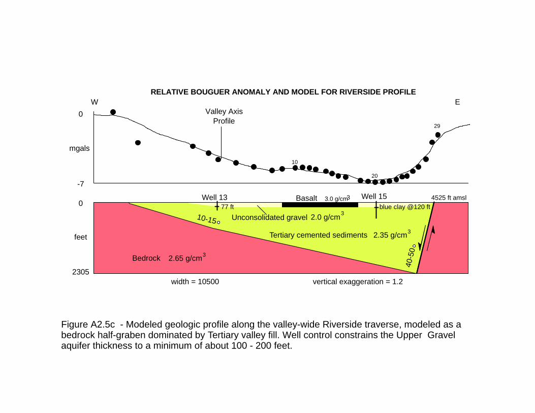
0
mgals
-7
0
feet
2305width = 10500 vertical exaggeration = 1.2
RELATIVE BOUGUER ANOMALY AND MODEL FOR RIVERSIDE PROFILE
Tertiary cemented sediments 2.35 g/cm 3
Unconsolidated gravel 2.0 g/cm 3
Bedrock 2.65 g/cm 3
40-5
0
77 ftWell 13 Well 15
Valley AxisProfile
10-15
Basalt 3.0 g/cm 3 4525 ft amsl
W E
blue clay @120 ft
10
20
29
Figure A2.5c - Modeled geologic profile along the valley-wide Riverside traverse, modeled as a bedrock half-graben dominated by Tertiary valley fill. Well control constrains the Upper Gravel aquifer thickness to a minimum of about 100 - 200 feet.

RELATIVE BOUGUER ANOMALY AND MODEL OF INDIAN HILLS PROFILE
0
-1
0
mgals
feet
317vertical exaggeration = 3.5width = 4200 feet
Tertiary cemented sediments
Unconsolidated gravel
Basalt
2.35 g/cm 3
2.0 g/cm 3
3.0 g/cm 3
Valley AxisProfile
PMW-1
68 feet
4465 ft amsl
W E
Reese(1200 ft south)
Well 33(2500 ft south)
150-165 ft
cementedgravel
Albright
Figure A2.5d - Modeled geologic profile along the Indian Hills traverse. The principal feature at this location is the substantial relief of the Tertiary paleo-valley (and/or Bonneville flood-scouring) and the thinning of the Upper Gravels, a feature that is corroborated by steeper and divergent water table gradients in this area (CH2M-Hill, 1995). The magnitude of the gravity high reflects not only paleo-valley topography but also the presence of shallow basalt. Basalt was not noted in nearby drillers' logs (Albright and Reese well), so it is assumed to be a flood-deposited boulder bar or a discontinuous remnant of an older, possibly Tertiary-age basalt lava flow.
(cemented rock)
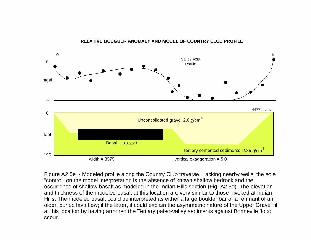
0
mgal
-1
0
feet
190width = 3575 vertical exaggeration = 5.0
RELATIVE BOUGUER ANOMALY AND MODEL OF COUNTRY CLUB PROFILE
Tertiary cemented sediments
2.0 g/cm 3Unconsolidated gravel
2.35 g/cm 3
W EValley Axis Profile
Basalt 3.0 g/cm 3
4477 ft amsl
Figure A2.5e - Modeled profile along the Country Club traverse. Lacking nearby wells, the sole "control" on the model interpretation is the absence of known shallow bedrock and the occurrence of shallow basalt as modeled in the Indian Hills section (Fig. A2.5d). The elevation and thickness of the modeled basalt at this location are very similar to those invoked at Indian Hills. The modeled basalt could be interpreted as either a large boulder bar or a remnant of an older, buried lava flow; if the latter, it could explain the asymmetric nature of the Upper Gravel fill at this location by having armored the Tertiary paleo-valley sediments against Bonnevile flood scour.

mgals
0
-1
0
feet
248width = 3800 vertical exaggeration = 4.1
RELATIVE BOUGUER ANOMALY AND MODEL OF BALL PARK PROFILE
Unconsolidated gravel 2.0 g/cm 3 Tertiary cemented sediments2.35 g/cm 3
W E
Valley AxisProfile
84
149170
PA-2
PA-4
PA-7
Basalt3.0 g/cm 3
4484 ft amslPA-1
(PA-
9)
98
1250 ft southof this section
Figure A2.5f - Modeled geologic profile along the Ball Park traverse, constrained by depths to the base of the Upper Gravel in test wells PA-1, 2, 4, and 9 and the new Hildreth domestic well. PA-7 bottomed in 5 ft of basalt beneath several feet of silty gravels comprising reworked Tertiary clasts (ash, breccia, mudstone). Although the modeled lava thickness is similar to that in Figures A2.5d and e, its surface is approximately 100 feet lower. Plastic clay encountered in PA-1, just a few feet above the basalt, suggests that it may be an older lava flow than those modeled in Figures A2.5d and e.
80
New
Hild
reth
1250 ft northof this section
159

RELATIVE BOUGUER ANOMALY AND MODEL OF MINK CREEK PROFILE
Bedrock
Tertiary cemented sediments
W E
Valley AxisProfile
Unconsolidated gravel
mgals
feet
0
-2
0
800width = 8100 vertical exaggeration = 2.7
2.65 g/cm 3
2.35 g/cm 3
2.0 g/cm 3Basalt 3.0 g/cm 3 4521 ft amsl
25-3
5
2030
40
Figure A2.5g - Modeled geologic profile along the Mink Creek traverse. Despite the lack of well control, all four rock densities were incorporated here on the basis of the geologic conceptual model. As in the Riverside section, the gravity data were modeled as a bedrock half-graben. The unconsolidated gravels at the top of the section are equivalent to the Upper Gravel (Bonneville flood deposits) west of, and the clayey/silty alluvial gravels east of, the Portneuf Basalt lava fow, respectively.
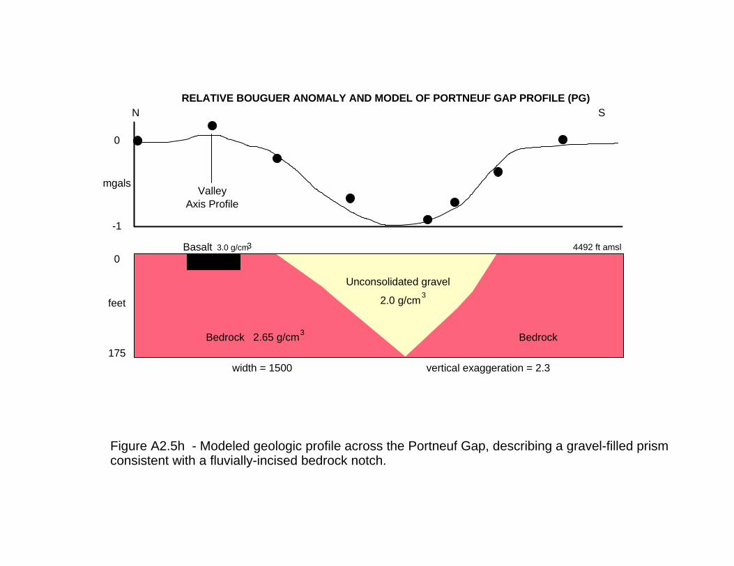
0
mgals
-1
0
feet
175width = 1500 vertical exaggeration = 2.3
RELATIVE BOUGUER ANOMALY AND MODEL OF PORTNEUF GAP PROFILE (PG)N
Bedrock 2.65 g/cm 3
Unconsolidated gravel
2.0 g/cm 3
ValleyAxis Profile
Bedrock
Basalt 3.0 g/cm 3 4492 ft amsl
S
Figure A2.5h - Modeled geologic profile across the Portneuf Gap, describing a gravel-filled prism consistent with a fluvially-incised bedrock notch.

RELATIVE BOUGUER ANOMALY AND MODEL OF KRAFT ROAD PROFILE (KR)
0
mgals
-14
0
feet
2860width = 35000 vertical exaggeration = 4.2
Tertiary cemented sediments2.35 g/cm 3Bedrock
2.65 g/cm 3
8-15
W E
Bedrock2.65 g/cm 3
4462 ft amsl
Valley Axis Profile
?
Fairgrounds Well
604 ft
Figure A2.5i - Modeled bedrock geology across the northernmost portion of the valley, along the Kraft road traverse. Lacking deep well control, bedrock stucture was modeled as a northward continuation of the half-graben identified in southern profiles, in order to be consistent with current interpretations of valley bedrock structure (Rodgers, pers. comm., 2000).
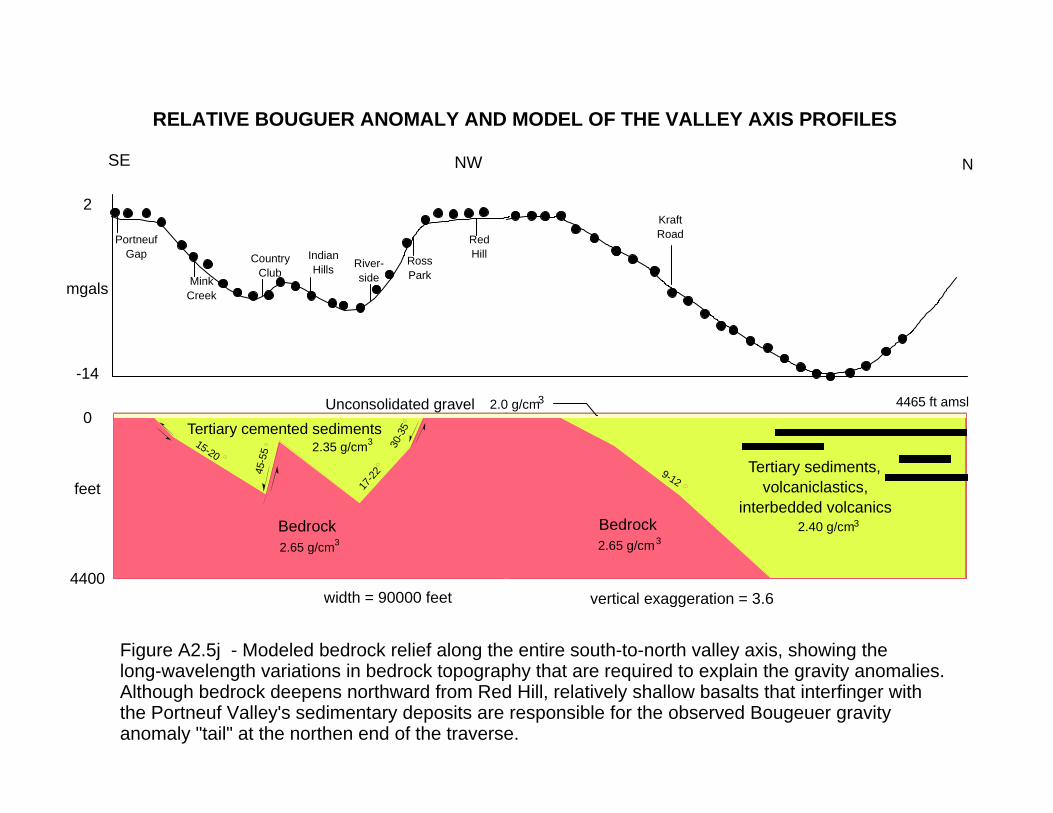
RELATIVE BOUGUER ANOMALY AND MODEL OF THE VALLEY AXIS PROFILES
vertical exaggeration = 3.6
Bedrock2.65 g/cm 3
Tertiary sediments,volcaniclastics,
interbedded volcanics2.40 g/cm 3
9-12
4465 ft amsl
N
2
mgals
-14
0
feet
4400
SE NW
width = 90000 feet
Tertiary cemented sediments2.35 g/cm 3
45-5
5
15-20
30-3
5
17-22
PortneufGap
MinkCreek
CountryClub
IndianHills River-
sideRossPark
RedHill
KraftRoad
Bedrock2.65 g/cm 3
Unconsolidated gravel 2.0 g/cm 3
Figure A2.5j - Modeled bedrock relief along the entire south-to-north valley axis, showing the long-wavelength variations in bedrock topography that are required to explain the gravity anomalies. Although bedrock deepens northward from Red Hill, relatively shallow basalts that interfinger with the Portneuf Valley's sedimentary deposits are responsible for the observed Bougeuer gravity anomaly "tail" at the northen end of the traverse.

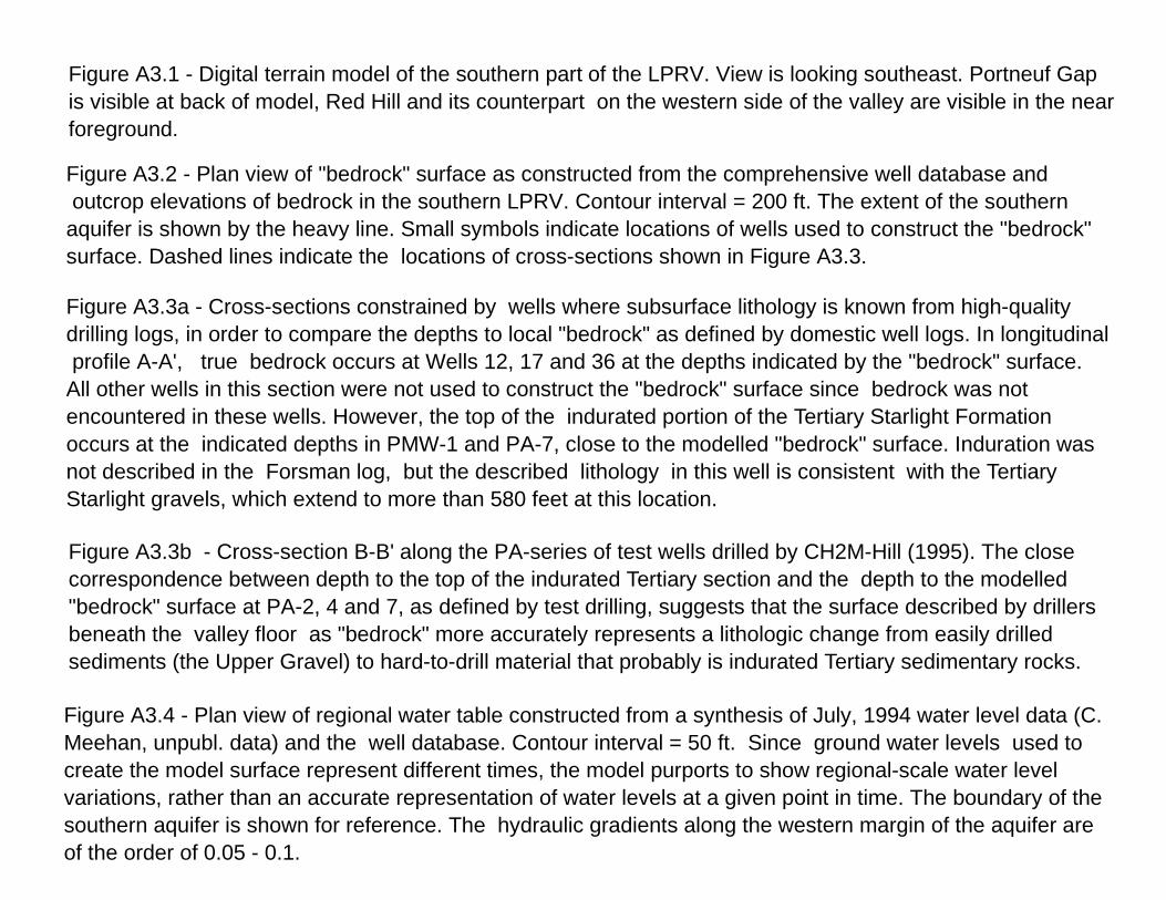
Figure A3.1 - Digital terrain model of the southern part of the LPRV. View is looking southeast. Portneuf Gap is visible at back of model, Red Hill and its counterpart on the western side of the valley are visible in the nearforeground.
Figure A3.2 - Plan view of "bedrock" surface as constructed from the comprehensive well database and outcrop elevations of bedrock in the southern LPRV. Contour interval = 200 ft. The extent of the southern aquifer is shown by the heavy line. Small symbols indicate locations of wells used to construct the "bedrock" surface. Dashed lines indicate the locations of cross-sections shown in Figure A3.3. Figure A3.3a - Cross-sections constrained by wells where subsurface lithology is known from high-qualitydrilling logs, in order to compare the depths to local "bedrock" as defined by domestic well logs. In longitudinal profile A-A', true bedrock occurs at Wells 12, 17 and 36 at the depths indicated by the "bedrock" surface. All other wells in this section were not used to construct the "bedrock" surface since bedrock was not encountered in these wells. However, the top of the indurated portion of the Tertiary Starlight Formation occurs at the indicated depths in PMW-1 and PA-7, close to the modelled "bedrock" surface. Induration was not described in the Forsman log, but the described lithology in this well is consistent with the Tertiary Starlight gravels, which extend to more than 580 feet at this location.
Figure A3.3b - Cross-section B-B' along the PA-series of test wells drilled by CH2M-Hill (1995). The closecorrespondence between depth to the top of the indurated Tertiary section and the depth to the modelled "bedrock" surface at PA-2, 4 and 7, as defined by test drilling, suggests that the surface described by drillersbeneath the valley floor as "bedrock" more accurately represents a lithologic change from easily drilled sediments (the Upper Gravel) to hard-to-drill material that probably is indurated Tertiary sedimentary rocks.
Figure A3.4 - Plan view of regional water table constructed from a synthesis of July, 1994 water level data (C.Meehan, unpubl. data) and the well database. Contour interval = 50 ft. Since ground water levels used to create the model surface represent different times, the model purports to show regional-scale water level variations, rather than an accurate representation of water levels at a given point in time. The boundary of the southern aquifer is shown for reference. The hydraulic gradients along the western margin of the aquifer are of the order of 0.05 - 0.1.