drive-based technology 4 - siemens · drive-based technology ... this manual contains notices you...
TRANSCRIPT
� Drive- �Based Technology
___________________
___________________
___________________
___________________
___________________
___________________
___________________
___________________
___________________
___________________
SIMOCRANE
Drive-Based Technology
Operating Instructions
valid for SIMOCRANE Drive-Based Technology V1.0 SP1 Hardware - SINAMICS CU310-2 - firmware V4.5 (for cranes)
07/2012
Preface
System overview 1
Hardware interfaces 2
Software structure 3
DCC blocks 4
Communication 5
Commissioning 6
Standard applications and adaptation options
7
Spare parts / accessories 8
Appendix A
Siemens AG Industry Sector Postfach 48 48 90026 NÜRNBERG GERMANY
Ⓟ 08/2012 Technical data subject to change
Copyright © Siemens AG 2010 - 2012.All rights reserved
Legal information Warning notice system
This manual contains notices you have to observe in order to ensure your personal safety, as well as to prevent damage to property. The notices referring to your personal safety are highlighted in the manual by a safety alert symbol, notices referring only to property damage have no safety alert symbol. These notices shown below are graded according to the degree of danger.
DANGER indicates that death or severe personal injury will result if proper precautions are not taken.
WARNING indicates that death or severe personal injury may result if proper precautions are not taken.
CAUTION indicates that minor personal injury can result if proper precautions are not taken.
NOTICE indicates that property damage can result if proper precautions are not taken.
If more than one degree of danger is present, the warning notice representing the highest degree of danger will be used. A notice warning of injury to persons with a safety alert symbol may also include a warning relating to property damage.
Qualified Personnel The product/system described in this documentation may be operated only by personnel qualified for the specific task in accordance with the relevant documentation, in particular its warning notices and safety instructions. Qualified personnel are those who, based on their training and experience, are capable of identifying risks and avoiding potential hazards when working with these products/systems.
Proper use of Siemens products Note the following:
WARNING Siemens products may only be used for the applications described in the catalog and in the relevant technical documentation. If products and components from other manufacturers are used, these must be recommended or approved by Siemens. Proper transport, storage, installation, assembly, commissioning, operation and maintenance are required to ensure that the products operate safely and without any problems. The permissible ambient conditions must be complied with. The information in the relevant documentation must be observed.
Trademarks All names identified by ® are registered trademarks of Siemens AG. The remaining trademarks in this publication may be trademarks whose use by third parties for their own purposes could violate the rights of the owner.
Disclaimer of Liability We have reviewed the contents of this publication to ensure consistency with the hardware and software described. Since variance cannot be precluded entirely, we cannot guarantee full consistency. However, the information in this publication is reviewed regularly and any necessary corrections are included in subsequent editions.
Drive-Based Technology Operating Instructions, 07/2012 3
Preface
This document is part of the SIMOCRANE Drive-Based Technology product. It describes the DCC blocks for crane technology, control via PROFIBUS DP or terminals (I/O) and the standard application solution for cranes. The standard application is suitable for both "Ready-to-Run" applications (parameterization only) and "Ready-to-Apply" applications (adapted by users).
Prerequisite (area of validity) This manual is valid for use with SINAMICS S120 in conjunction with the following product versions:
Hardware:
● SINAMICS CU310-2
● Firmware V4.5 (for cranes)
Software:
● STARTER V4.3.1
● SINAMICS DCC V2.2 SP1 option package
● SIMOCRANE Drive-Based Technology V1.0 SP1
Additional information The latest information about SINAMICS products, product support, and FAQs can be found on the Internet here (http://support.automation.siemens.com/WW/view/en/13305690/130000).
The latest information about SIMOCRANE products, product support, and FAQs can be found on the Internet here (http://support.automation.siemens.com/WW/view/en/10807397/130000).
You can find information about Crane Application Notes on the Internet here (http://support.automation.siemens.com/WW/view/en/48342008/136000).
Application support for cranes
E-mail: [email protected] (mailto:[email protected])

Preface
Drive-Based Technology 4 Operating Instructions, 07/2012
Product support for SIMOCRANE
Use the following addresses to receive support for your SIMOCRANE products:
● Support request in the Internet:
http://support.automation.siemens.com
● Europe hotline
– Tel.: +49 (0) 911 895 7 222
– Fax: +49 (0) 911 895 7 223
– E-mail: [email protected]
● America hotline
– Tel.: +1 423 262 5710
– Fax: +1 423 262 2231
– E-mail: [email protected]
● Asia/Pacific hotline
– Tel.: +86 10 6475 7575
– Fax: +86 10 6474 7474
– E-mail: [email protected]
Additional support
We also offer training courses to help you familiarize yourself with SIMOCRANE Drive-Based Technology. You can find more information here (www.siemens.nl/training/cranes).
If you have any additional questions please contact your local Siemens sales person.

Drive-Based Technology Operating Instructions, 07/2012 5
Table of contents
Preface ...................................................................................................................................................... 3
1 System overview........................................................................................................................................ 7
2 Hardware interfaces................................................................................................................................. 11
2.1 Handling a CU310-2 CF card.......................................................................................................11
2.2 CU310-2 interfaces ......................................................................................................................11
2.3 BOP20 Basic Operator Panel ......................................................................................................14
3 Software structure.................................................................................................................................... 17
3.1 Closed-loop control structure .......................................................................................................18
4 DCC blocks.............................................................................................................................................. 21
4.1 General information .....................................................................................................................21
4.2 DCC block MasterSwitch .............................................................................................................24
4.3 DCC block StartPulse ..................................................................................................................28
4.4 DCC block PreLimitSwitch ...........................................................................................................30
4.5 DCC block OverSpeed.................................................................................................................33
4.6 DCC block CurrentDistribution.....................................................................................................38
4.7 DCC block LoadDependingFieldWeak ........................................................................................41
5 Communication........................................................................................................................................ 47
5.1 Task distribution...........................................................................................................................47
5.2 Configuring the PROFIBUS connection.......................................................................................49 5.2.1 Communication SIMATIC → SINAMICS ......................................................................................52 5.2.2 Communication SINAMICS → SIMATIC ......................................................................................54
5.3 Configuring the I/O connection ....................................................................................................59
6 Commissioning ........................................................................................................................................ 63
6.1 General information .....................................................................................................................63
6.2 Controlling the crane taking the PROFIdrive profile into account................................................66 6.2.1 Switch on the drive.......................................................................................................................66 6.2.2 Switch off the drive.......................................................................................................................68 6.2.3 Mechanical motion stop ...............................................................................................................69
6.3 SINAMICS drive object ................................................................................................................69
6.4 Cranes DCC blocks .....................................................................................................................75
6.5 Function (DCC block) "Load-dependent field weakening"...........................................................76 6.5.1 Theoretical basics and equations ................................................................................................76 6.5.2 Commissioning instructions .........................................................................................................77 6.5.2.1 Generating the measured variables.............................................................................................77

Table of contents
Drive-Based Technology 6 Operating Instructions, 07/2012
6.5.2.2 Compensating the frictional torque ............................................................................................. 79 6.5.2.3 Correcting the efficiency.............................................................................................................. 79 6.5.2.4 Calculating the physical size of the load ..................................................................................... 81 6.5.3 Criteria for enabling field weakening........................................................................................... 81 6.5.4 Load curves in examples ............................................................................................................ 82 6.5.4.1 Example 1: Constant power ........................................................................................................ 82 6.5.4.2 Example 2: Curve is specified (no constant power).................................................................... 83
6.6 The trace function ....................................................................................................................... 86 6.6.1 Recording DCC input and output parameters............................................................................. 87
7 Standard applications and adaptation options ......................................................................................... 89
7.1 Standard application, SingleAxis ................................................................................................ 90 7.1.1 Setpoint channel ......................................................................................................................... 91 7.1.2 StartPulse in combination with brake control .............................................................................. 95
7.2 Master-slave operation for SingleAxis ........................................................................................ 96
7.3 Expanding a standard application and DCC chart...................................................................... 98
7.4 Data units .................................................................................................................................... 99
7.5 Converting a BiCo parameter into an adjustable parameter..................................................... 100
8 Spare parts / accessories ...................................................................................................................... 107
A Appendix................................................................................................................................................ 109
A.1 List of References ..................................................................................................................... 109
A.2 Abbreviations ............................................................................................................................ 109
A.3 Differences to Basic Technology from a terminology perspective............................................ 110
Drive-Based Technology Operating Instructions, 07/2012 7
System overview 1
A sector solution based on the platform of SIMOTION / SINAMICS SIMOCRANE Basic Technology was launched into the market in the middle of 2007. The new platform based on SIMATIC + SIMOTION + SINAMICS is available for both harbor and industrial cranes. The solution covers high-performance crane applications and allows a modular, scalable closed-loop control system for all types of cranes (Ref. [6]) by adding the Advanced Technology (e.g. Sway Control).
However, in the meantime, the industrial crane market has developed further at a fast rate. As a consequence, in recent years a broad range of applications for mid-performance cranes has been opened up. With SIMOCRANE Drive-Based Technology, Siemens Crane meets the challenges of this market.
The new mid-performance crane solution will not take market share from SIMOCRANE Basic Technology. In fact, the SIMOCRANE Drive-Based Technology perfectly adapts this high performance solution to the mid-performance market.
SIMOCRANE Drive-Based Technology is drive-based and offers a compact functional scope within the SINAMICS environment. Highlights of Drive-Based Technology are fast commissioning by using standard applications and a high degree of flexibility through the appropriate adaptation possibilities.
SIMOCRANE Drive-Based Technology encompasses the following features:
● All of the functions that have been proven in practice and required for mid-performance applications can be found on the new SINAMICS platform for parameterization.
● Preconfigured standard applications for hoist and trolley/gantry with control via I/O signals or PROFIBUS DP (ready-to-run, parameterization only, selection using a script).
● Can be adapted for customer-specific requirements - "Ready-to-apply" (for adaptation by the user).
V1.0 SP1 special feature The SIMOCRANE Drive-Based Technology V1.0 with SINAMICS CU310 was launched on the market at the end of 2010. The innovation of the SINAMICS CU310-2 developed a crane-specific SINAMICS firmware so that the CU310-2 can operate the PM340 Power Modules, PM Chassis and PM250. The focus of the new version SIMOCRANE Drive-Based Technology V1.0 SP1 is the adaptation to the market requirement and the further developed SINAMICS software and hardware.
The functional scope has been moderately expanded for the new version. The new onboard I/O on the CU310-2 simplifies the control of the standard application. This saves the need for an additional Terminal Module for simple applications. Other customer requirements are taken into account in applications, such as digital master switch, combination between StartPulse and SINAMICS brake control system, commissioning using the BOP20, etc.

System overview
Drive-Based Technology 8 Operating Instructions, 07/2012
Scope of supply The previous SIMOCRANE Drive-Based Technology V1.0 with SINAMICS CU310 (order number: 6GA7270-1AA10-0AA0) package will continue to be sold. In parallel, the SIMOCRANE Drive-Based Technology V1.0 SP1 with SINAMICS CU310-2 (order number: 6GA7270-1AA11-0AA0) package is supplied. This means as customer you can choose between these two packages depending on the project and the system.
The SIMOCRANE Drive-Based Technology scope of delivery includes:
SIMOCRANE Drive-Based Technology V1.0
● One memory card (CF card)
– with the firmware version for SINAMICS S120 (V2.6.2)
● One CD with
– Cranes DCC blocks
– Standard applications
– Documentation
SIMOCRANE Drive-Based Technology V1.0 SP1
● One memory card (CF card)
– with crane-specific firmware version for SINAMICS S120 (V4.5)
● One CD with
– Cranes DCC blocks
– Standard applications
– Documentation
System overview
Drive-Based Technology Operating Instructions, 07/2012 9
Functional scope
Table 1- 1 SIMOCRANE Drive-Based Technology functional scope
No. Function Brief description 1 Load-dependent field weakening
Using the LoadDependingFieldWeak DCC block, a supplementary speed setpoint is calculated dependent on the load. This speed increase for partial loads above the rated speed is required for cranes to increase the handling capacity.
2 Prelimit switch (selectable limiting)
Using this DCC block, when a pre-defined pre-limit switch is reached, the drive velocity can be limited.
3 Start pulse
Using this DCC block, "load sag" when starting hoisting gear with a suspended load is prevented.
4 Current distribution monitoring
This DCC block is used to compare the current setpoint or actual value of the master and slave. A message is generated if a specified difference is exceeded.
5 Master switch
Using this DCC block, the drive can be moved with a fine sensitivity via a directly connected master switch for manual positioning.
6 Overspeed monitoring
Using the DCC block OverSpeed, the overspeed can be monitored or a setpoint-actual value deviation can be identified (this is not a fail-safe function).
7 Time-optimized positioning for a single axis
Using the function module "basic positioning" in SINAMICS, the drive can be moved to the target position as quickly as possible and precisely with the specified maximum velocity and acceleration/deceleration.
8 Master-slave closed-loop torque control
Master-slave operation is used if two motors are connected to a common shaft. The master operates either in the closed-loop speed or position controlled mode, the slave operates in the closed-loop torque controlled mode. The master sends the torque as torque setpoint to the slave. The communication between master-slave drive must be performed as part of the application solution.
9 Brake control The simple or extended brake control allows the user to parameterize rather than program the control. The combination of start pulse and brake control simplifies the engineering and commissioning for the user.
10 Safety Integrated If required, the SINAMICS Safety Integrated basic and extended functions are available for the user, e.g. STO, SLS.

System overview
Drive-Based Technology 10 Operating Instructions, 07/2012
Drive-Based Technology Operating Instructions, 07/2012 11
Hardware interfaces 22.1 Handling a CU310-2 CF card
The firmware and parameters with the factory settings are stored on the CF card inserted in the CU310-2 Control Unit.
Note
The CF card may only be inserted in the Control Unit when in the no-voltage condition.
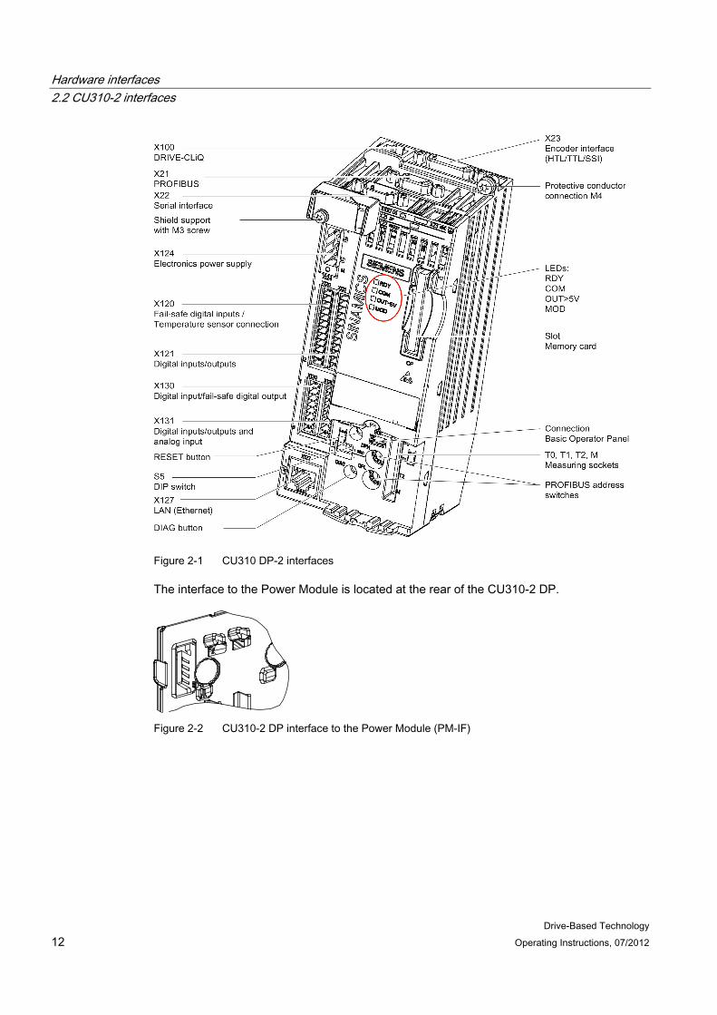
2.2 CU310-2 interfaces The CU310-2 DP Control Unit (PROFIBUS) is a control module for single-motor drives in which the open-loop and closed-loop control functions of the drive are implemented. It controls the Power Modules in the blocksize format via the PM-IF interface. The Chassis Power Modules are controlled from the Control Unit via the DRIVE-CLiQ interface.
The CU310-2 DP is hot-pluggable. It can be used as of firmware version 4.5 (for cranes).
The table shows an overview of the interfaces on the CU310-2 DP.
Table 2- 1 Overview of the interfaces on the CU310-2 DP
Type Number Isolated digital inputs 11 Non-isolated digital inputs/outputs 8 Isolated digital output 1 Non-isolated analog input 1 DRIVE-CLiQ interface 1 PROFIBUS interface 1 Serial interface (RS232) 1 Encoder interface (HTL/TTL/SSI) 1 LAN (Ethernet) 1 Temperature sensor input 1 EP terminal 1 Test sockets 3
Hardware interfaces 2.2 CU310-2 interfaces
Drive-Based Technology 12 Operating Instructions, 07/2012
Figure 2-1 CU310 DP-2 interfaces
The interface to the Power Module is located at the rear of the CU310-2 DP.
Figure 2-2 CU310-2 DP interface to the Power Module (PM-IF)
Hardware interfaces 2.2 CU310-2 interfaces
Drive-Based Technology Operating Instructions, 07/2012 13
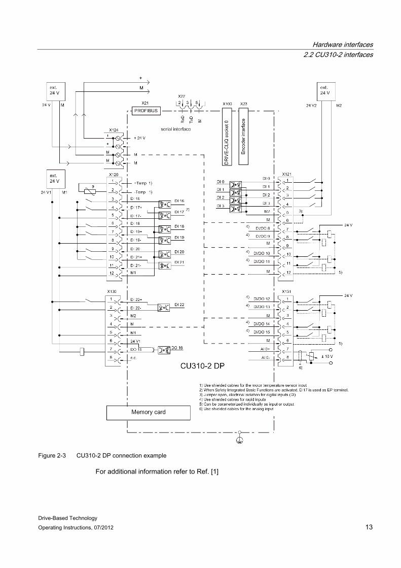
Figure 2-3 CU310-2 DP connection example
For additional information refer to Ref. [1]
Hardware interfaces 2.3 BOP20 Basic Operator Panel
Drive-Based Technology 14 Operating Instructions, 07/2012
2.3 BOP20 Basic Operator Panel
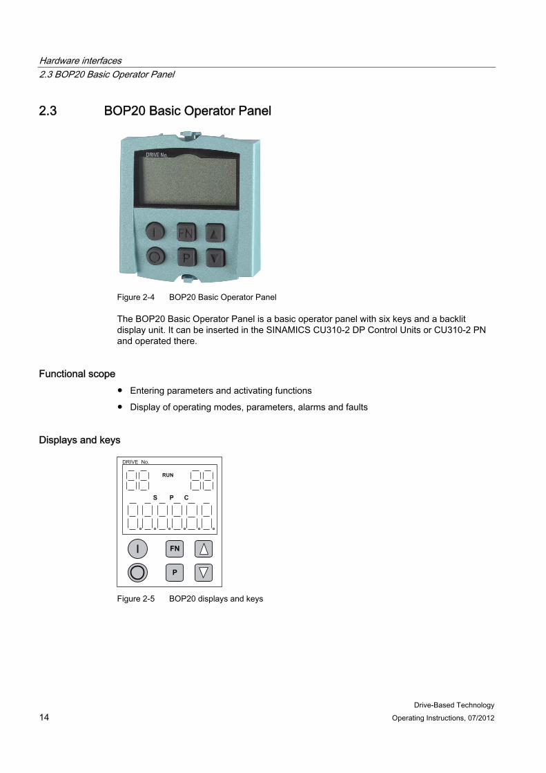
Figure 2-4 BOP20 Basic Operator Panel
The BOP20 Basic Operator Panel is a basic operator panel with six keys and a backlit display unit. It can be inserted in the SINAMICS CU310-2 DP Control Units or CU310-2 PN and operated there.
Functional scope ● Entering parameters and activating functions
● Display of operating modes, parameters, alarms and faults
Displays and keys
S CP
RUN
FN
P
Figure 2-5 BOP20 displays and keys

Hardware interfaces 2.3 BOP20 Basic Operator Panel
Drive-Based Technology Operating Instructions, 07/2012 15
Table 2- 2 Displays
Display Meaning top left
2 positions The active drive object of the BOP is displayed here. The displays and key operations always refer to this drive object.
RUN It illuminates when the displayed drive is in the RUN state (in operation). top right
2 positions The following is displayed in this field: • More than 6 digits: characters that still exist but are not visible
(e.g. "r2": two characters to the right are not visible, "L1": one character to the left is not visible)
• Faults: selects/displays other drives with faults • Designation of BICO inputs (bi, ci) • Designation of BICO outputs (bo, co) • The source object of a BICO interconnection to a drive object differs from the
active one
S It illuminates when at least one parameter was changed and the value was not transferred to the non-volatile memory.
P It illuminates when the value for a parameter becomes effective only after pressing the P key.
C It illuminates when at least one parameter was changed and the calculation for consistent data management has still not been initiated.
Below, 6 digit Displays, e.g. parameters, indices, faults and alarms.
Table 2- 3 BOP20 keys 1)
Key Name Effect
ON 2) Power-up the drives for which the "ON/OFF1", "OFF2" or "OFF3"
commands should come from the BOP.
OFF 2) Power-down the drives for which the "ON/OFF1", "OFF2" or "OFF3"
commands should come from the BOP.
FN
Functions 3) The effect of this key depends on the current display.
P Parameter The effect of this key depends on the current display.
Raise
Lower
These keys depend on the current display; use these keys to set the displayed values higher or lower.
1) The structure of the BOP control word corresponds to the structure of the PROFIBUS control word. 2) The effect of this key can be defined using the appropriate BICO parameterization (for example,
you can use this key to control all axes concurrently). 3) The effect of this key to acknowledge faults can be defined using the appropriate BICO
parameterization.
Hardware interfaces 2.3 BOP20 Basic Operator Panel
Drive-Based Technology 16 Operating Instructions, 07/2012
Note
Further information about the BOP20 is contained in the SINAMICS S120 Commissioning Manual.
Drive-Based Technology Operating Instructions, 07/2012 17
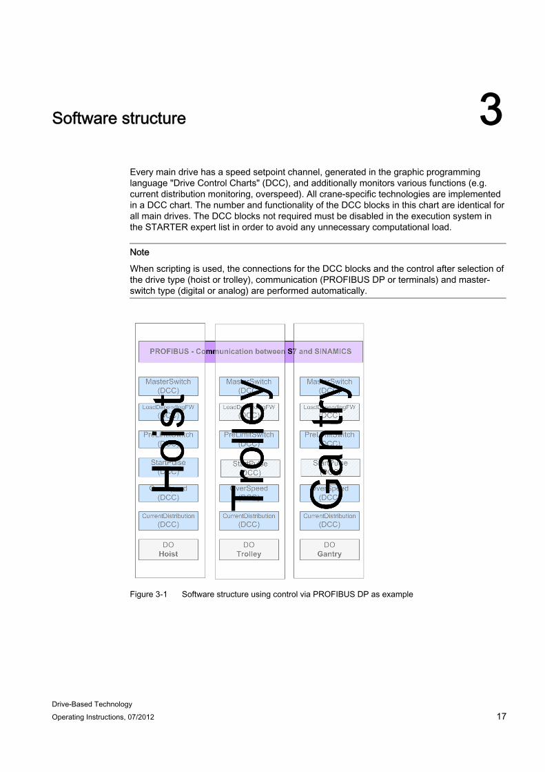
Software structure 3
Every main drive has a speed setpoint channel, generated in the graphic programming language "Drive Control Charts" (DCC), and additionally monitors various functions (e.g. current distribution monitoring, overspeed). All crane-specific technologies are implemented in a DCC chart. The number and functionality of the DCC blocks in this chart are identical for all main drives. The DCC blocks not required must be disabled in the execution system in the STARTER expert list in order to avoid any unnecessary computational load.
Note
When scripting is used, the connections for the DCC blocks and the control after selection of the drive type (hoist or trolley), communication (PROFIBUS DP or terminals) and master-switch type (digital or analog) are performed automatically.
Figure 3-1 Software structure using control via PROFIBUS DP as example

Software structure 3.1 Closed-loop control structure
Drive-Based Technology 18 Operating Instructions, 07/2012
3.1 Closed-loop control structure A speed setpoint is read in from the S7 or from the Onboard Terminals. This speed setpoint is connected to the input of the Crane DCC block MasterSwitch. The setpoint is then transferred to the main setpoint channel of the SINAMICS basic system after processing via the DCC blocks LoadDependingFieldWeak and PreLimitSwitch; refer to the following diagrams.
Figure 3-2 Hoist setpoint channel using the example of control via PROFIBUS
Figure 3-3 Gantry/trolley setpoint channel using the example of the control via PROFIBUS

Software structure 3.1 Closed-loop control structure
Drive-Based Technology Operating Instructions, 07/2012 19
Speed path The setpoint speed is first interconnected to the block MasterSwitch in the DCC. If the master switch functionality is to be used, then the master switch curve must be configured and enabled. Otherwise, the speed setpoint is directly connected from the input to the block output without any change.
The speed setpoint is then connected to the LoadDependingFieldWeak block (only for hoisting gear applications). When traveling at a constant speed in the rated speed range, this block determines the load. The maximum speed is limited as a function of the load.
The speed setpoint is further connected to the PreLimitSwitch block. Depending on the control, the setpoint speed is reduced. Finally, the setpoint speed is interconnected with the main setpoint of the SINAMICS basic system.
Note
The StartPulse function is combined with the SINAMICS brake control, see Section StartPulse in combination with brake control (Page 95).
Note
The output signal of the digital master switch is evaluated by the application and interconnected with the DigitalMasterSwitch DCC block. The output of the digital master switch supplies an incremental speed setpoint, see Section Setpoint channel (Page 91).

Software structure 3.1 Closed-loop control structure
Drive-Based Technology 20 Operating Instructions, 07/2012
Drive-Based Technology Operating Instructions, 07/2012 21
DCC blocks 44.1 General information
The SIMOCRANE Cranes DCC blocks contain the crane technology functions.
Note
Each main drive has a DCC chart that contains the crane-technology functions. The DCC chart is closed and the DCC blocks are adapted to the requirements of the application via the appropriate parameters in the expert list.
Additional DCC applications can be implemented using a separate DCC chart under the Control Unit or under another drive object. For additional information on this topic, refer to Expanding a standard application and DCC chart (Page 98) or Ref. [3]
Note
There is no online help in the expert list for the user-defined parameters.
WARNING Material damage as well as injury to personnel can occur if the preconfigured run sequence inside of the DCC blocks is changed.
If not otherwise noted, then the following statements apply to all DCC blocks:
Firmware version ● STARTER: Software V4.3.1 or higher
● SINAMICS: Firmware V4.5 (for cranes)
Configuration The DCC blocks can be configured in cyclic tasks. Any delays (dead times) must be avoided in the setpoint channel in configuring cyclic tasks.
The following sequence is recommended when all blocks are configured in one execution level:
1. Master switch
2. LoadDependingFieldWeak (is only required for hoisting gear applications)
3. PreLimitSwitch
4. StartPulse (is only required for hoisting gear applications)

DCC blocks 4.1 General information
Drive-Based Technology 22 Operating Instructions, 07/2012
5. OverSpeed
6. CurrentDistribution (is only required for synchronous operation or master-slave applications)
Setting tip
Master switch p21000[0] = [3005] PRE basic positioner LoadDependingFieldWeaking p21000[1] = [3005] PRE basic positioner PreLimitSwitch p21000[2] = [3005] PRE basic positioner StartPulse p21000[3] = [3005] PRE basic positioner OverSpeed p21000[4] = [3005] PRE basic positioner CurrentDistribution p21000[5] = [3005] PRE basic positioner
Explanation
All inputs/outputs of DCC blocks have a pre-assigned value. The value can be pre-assigned from two locations:
● If the input/output is not assigned, the default value applies.
● The input/output is linked to a parameter from the DCC block.
Internally, SINAMICS DCC operates only with percentage values, i.e. if a speed value is linked to a DCC block input, the absolute value in revolutions per minute is not used, but rather a percentage value in the DCC block. The conversion from absolute to percentage values is always implemented using the reference value in parameters p2000 to p2003 or r2700 to r2703.
This is the reason that the following declaration applies for the reference values:
● p2000 = r2700 = reference speed reference frequency ( ≈ p1082 = maximum speed)
● p2001 = r2701 = reference voltage
● p2002 = r2702 = reference current
● p2003 = r2703 = reference torque
Note
All reference data must be normalized to their maximum value: • nmax = nreference = 100% = nrated + nFw
(maximum speed = reference speed = rated speed + field weakening speed) • Imax = Ireference = 100% = Irated + Ioverload
(maximum current = reference current = rated current + overload current) • Mmax = Mreference = 100% = Mrated + Moverload
(maximum torque = reference torque = rated torque + overload torque)
DCC blocks 4.1 General information
Drive-Based Technology Operating Instructions, 07/2012 23
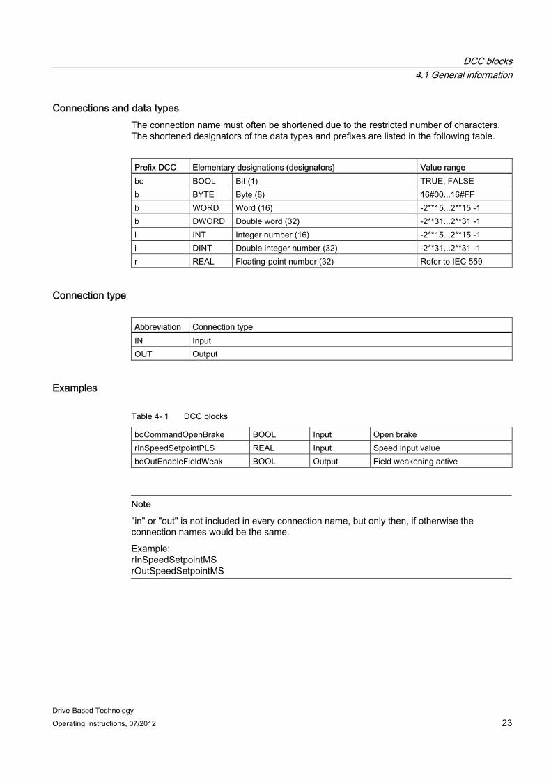
Connections and data types The connection name must often be shortened due to the restricted number of characters. The shortened designators of the data types and prefixes are listed in the following table.
Prefix DCC Elementary designations (designators) Value range bo BOOL Bit (1) TRUE, FALSE b BYTE Byte (8) 16#00...16#FF b WORD Word (16) -2**15...2**15 -1 b DWORD Double word (32) -2**31...2**31 -1 i INT Integer number (16) -2**15...2**15 -1 i DINT Double integer number (32) -2**31...2**31 -1 r REAL Floating-point number (32) Refer to IEC 559
Connection type Abbreviation Connection type IN Input OUT Output
Examples
Table 4- 1 DCC blocks
boCommandOpenBrake BOOL Input Open brake rInSpeedSetpointPLS REAL Input Speed input value boOutEnableFieldWeak BOOL Output Field weakening active
Note
"in" or "out" is not included in every connection name, but only then, if otherwise the connection names would be the same.
Example: rInSpeedSetpointMS rOutSpeedSetpointMS
DCC blocks 4.2 DCC block MasterSwitch
Drive-Based Technology 24 Operating Instructions, 07/2012
Note
In the expert list in STARTER, the name of the DCC block is used as a prefix for the parameter name, so that an allocation can be made to the particular DCC block, i.e. • in STARTER:
[parameter number] [name of the DCC block]_[parameter name] • in these operating instructions:
[parameter number] "[parameter name]"
Example: • in STARTER:
p22000 MasterSwitch_rInSpeedSetpointMS • in these operating instructions:
p22000 "rInSpeedSetpointMS".
Note
If a DCC input is linked with a value from the basic unit, then an automatic conversion is made to the drive connectors that have associated units.
If an interconnection is established to this input from another DCC chart, then this value may only be in the range -2.0 to +2.0.
In SINAMICS DCC, 100% corresponds to a value of 1.0, i.e. 200% corresponds to a value of 2.0.
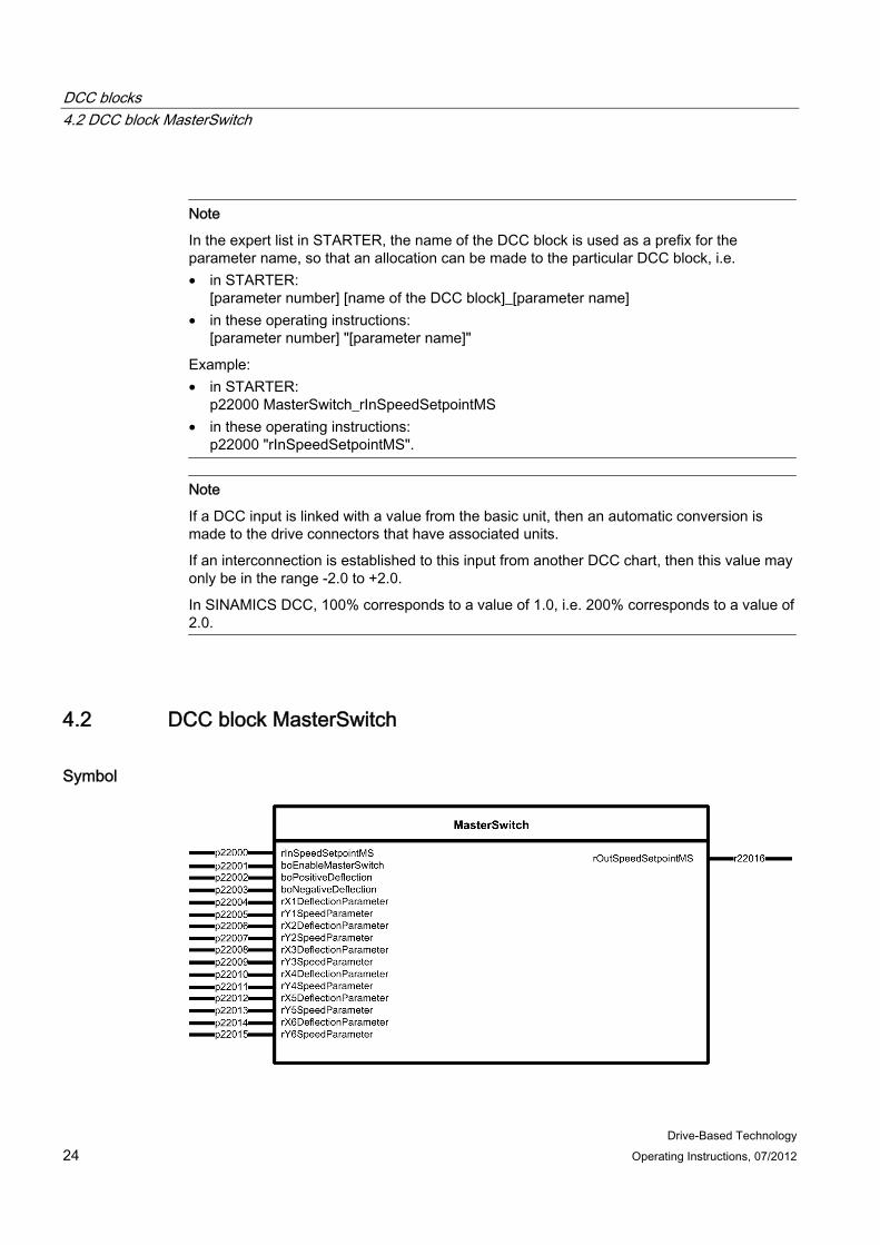
4.2 DCC block MasterSwitch
Symbol
DCC blocks 4.2 DCC block MasterSwitch
Drive-Based Technology Operating Instructions, 07/2012 25
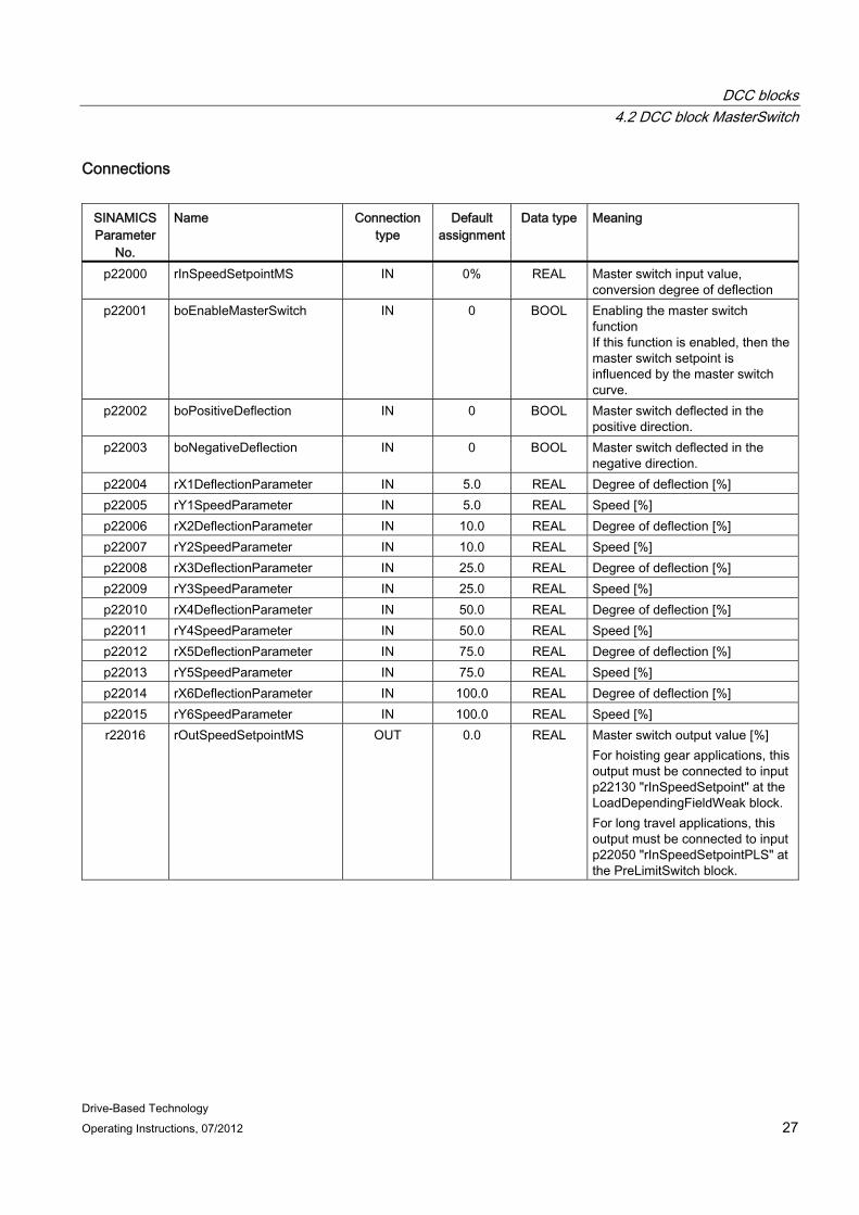
Short description Using the MasterSwitch DCC block - for manual positioning - the drive can be moved with a fine sensitivity via a directly connected master switch. This DCC block has a 6-point polygon function.
Mode of operation The master switch supplies a setpoint that is directly proportional to its angle of deflection. In order that for low deflection angles lower speed setpoints are obtained than those that correspond linearly to the deflection angle, the master switch setpoint is passed through a non-linear function. This allows the drive to be precisely positioned in the manual mode. For low deflection angles, this results in lower speed changes than for the same change of the deflection angle in the medium and higher deflection range. The non-linear function is realized in quadrant I using 6 adjustable straight-line sections, whereby the zero point is given. Quadrant III is mirrored as a result of the inputs from quadrant I.
The inputs p22002 "boPositiveDeflection" (positive deflection) and p22003 "boNegativeDeflection" (negative deflection) are read in. Depending on the polarity read in, either a positive or a negative speed setpoint is output at the block output. Only 1 input may be active at any time. However, if both inputs are active at the same time, or both inputs are not active, then the block outputs a speed setpoint of ZERO at its output. Further, for a positive setpoint input at the block input and if input p22003 "boNegativeDeflection" is set, then a negative speed setpoint is given at the block output. For a negative setpoint input at the block input and if input p22003 "boPositiveDeflection" is set, then a positive speed setpoint is given at the block output. The polarity of the setpoint input at the block input p22000 "rInSpeedSetpointMS" is not taken into account.
DCC blocks 4.2 DCC block MasterSwitch
Drive-Based Technology 26 Operating Instructions, 07/2012
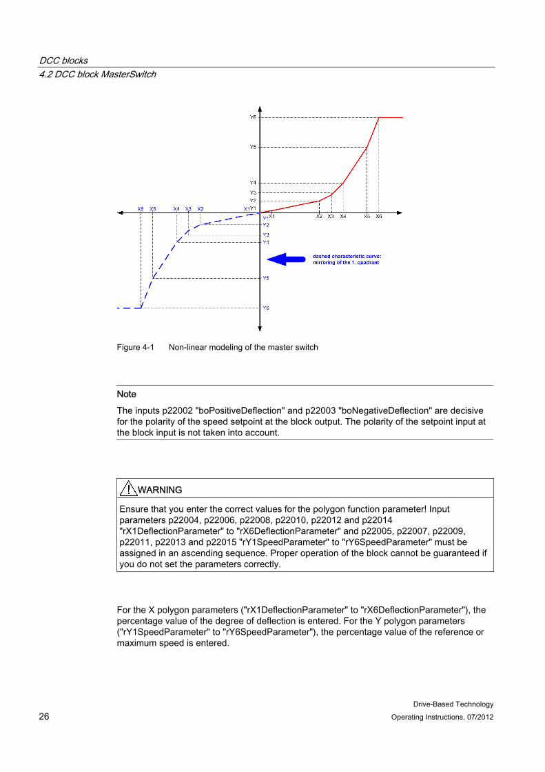
Figure 4-1 Non-linear modeling of the master switch
Note
The inputs p22002 "boPositiveDeflection" and p22003 "boNegativeDeflection" are decisive for the polarity of the speed setpoint at the block output. The polarity of the setpoint input at the block input is not taken into account.
WARNING Ensure that you enter the correct values for the polygon function parameter! Input parameters p22004, p22006, p22008, p22010, p22012 and p22014 "rX1DeflectionParameter" to "rX6DeflectionParameter" and p22005, p22007, p22009, p22011, p22013 and p22015 "rY1SpeedParameter" to "rY6SpeedParameter" must be assigned in an ascending sequence. Proper operation of the block cannot be guaranteed if you do not set the parameters correctly.
For the X polygon parameters ("rX1DeflectionParameter" to "rX6DeflectionParameter"), the percentage value of the degree of deflection is entered. For the Y polygon parameters ("rY1SpeedParameter" to "rY6SpeedParameter"), the percentage value of the reference or maximum speed is entered.
DCC blocks 4.2 DCC block MasterSwitch
Drive-Based Technology Operating Instructions, 07/2012 27
Connections
SINAMICS Parameter
No.
Name Connection type
Default assignment
Data type Meaning
p22000 rInSpeedSetpointMS IN 0% REAL Master switch input value, conversion degree of deflection
p22001 boEnableMasterSwitch IN 0 BOOL Enabling the master switch function If this function is enabled, then the master switch setpoint is influenced by the master switch curve.
p22002 boPositiveDeflection IN 0 BOOL Master switch deflected in the positive direction.
p22003 boNegativeDeflection IN 0 BOOL Master switch deflected in the negative direction.
p22004 rX1DeflectionParameter IN 5.0 REAL Degree of deflection [%] p22005 rY1SpeedParameter IN 5.0 REAL Speed [%] p22006 rX2DeflectionParameter IN 10.0 REAL Degree of deflection [%] p22007 rY2SpeedParameter IN 10.0 REAL Speed [%] p22008 rX3DeflectionParameter IN 25.0 REAL Degree of deflection [%] p22009 rY3SpeedParameter IN 25.0 REAL Speed [%] p22010 rX4DeflectionParameter IN 50.0 REAL Degree of deflection [%] p22011 rY4SpeedParameter IN 50.0 REAL Speed [%] p22012 rX5DeflectionParameter IN 75.0 REAL Degree of deflection [%] p22013 rY5SpeedParameter IN 75.0 REAL Speed [%] p22014 rX6DeflectionParameter IN 100.0 REAL Degree of deflection [%] p22015 rY6SpeedParameter IN 100.0 REAL Speed [%] r22016 rOutSpeedSetpointMS OUT 0.0 REAL Master switch output value [%]
For hoisting gear applications, this output must be connected to input p22130 "rInSpeedSetpoint" at the LoadDependingFieldWeak block. For long travel applications, this output must be connected to input p22050 "rInSpeedSetpointPLS" at the PreLimitSwitch block.

DCC blocks 4.3 DCC block StartPulse
Drive-Based Technology 28 Operating Instructions, 07/2012
4.3 DCC block StartPulse
Symbol
Brief description Using the StartPulse DCC block, when starting hoisting gear with a suspended load, so-called "load sag" is either prevented or reduced.
Note
The block is only required for hoisting gear applications. In hoisting gear applications, the block must be activated in the execution system (p21000[n]). For all other applications, the block must be deactivated in the execution system (p21000[n]).
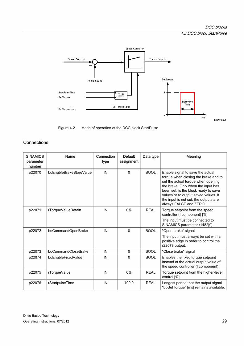
Mode of operation For hoisting gear, when starting - and therefore when opening the hoisting gear brakes - with freely suspended load, often the load undesirably sags. The cause is the missing torque that must first be established from the time when the command "open brake" is issued, which involves the processing time of the system. This means that when the command to open the brake is issued, the corresponding torque for the load must be available to prevent the load from sagging. This is achieved using the start pulse. To do this, the torque at the output of the speed controller at standstill is retentively saved with p22071 "rTorqueValueRetain" before the brake is closed. The speed controller is set to the retentively saved value using parameter r22077 "rSetTorqueValue" when the signal to open the brake is output. This means that the torque is quickly established - therefore preventing load sag.
The direction of the start pulse is always in the hoisting direction.
In addition, using parameter p22076 "rStartpulseTime", the time that output parameter r22078 "boSetTorque" remains available can be specified in milliseconds. The schematic of the logic circuitry is shown in the following diagram.
WARNING Incorrect start pulse values may lead to injury and material damage.
DCC blocks 4.3 DCC block StartPulse
Drive-Based Technology Operating Instructions, 07/2012 29
Figure 4-2 Mode of operation of the DCC block StartPulse
Connections
SINAMICS parameter
number
Name Connection type
Default assignment
Data type Meaning
p22070 boEnableBrakeStoreValue IN 0 BOOL Enable signal to save the actual torque when closing the brake and to set the actual torque when opening the brake. Only when the input has been set, is the block ready to save values or to output saved values. If the input is not set, the outputs are always FALSE and ZERO.
p22071 rTorqueValueRetain IN 0% REAL Torque setpoint from the speed controller (I component) [%]. The input must be connected to SINAMICS parameter r1482[0].
p22072 boCommandOpenBrake IN 0 BOOL "Open brake" signal The input must always be set with a positive edge in order to control the r22078 output.
p22073 boCommandCloseBrake IN 0 BOOL "Close brake" signal p22074 boEnableFixedValue IN 0 BOOL Enables the fixed torque setpoint
instead of the actual output value of the speed controller (I component).
p22075 rTorqueValue IN 0% REAL Torque setpoint from the higher-level control [%].
p22076 rStartpulseTime IN 100.0 REAL Longest period that the output signal "boSetTorque" [ms] remains available.

DCC blocks 4.4 DCC block PreLimitSwitch
Drive-Based Technology 30 Operating Instructions, 07/2012
SINAMICS parameter
number
Name Connection type
Default assignment
Data type Meaning
r22077 rSetTorqueValue OUT 0.0 REAL Torque setpoint [%] The output must be connected to SINAMICS parameter p1478[0].
r22078 boSetTorque OUT 0 BOOL Signal to set the torque when opening the brake. The output must be connected to SINAMICS parameter p1477[0].
Note
In the standard applications, the StartPulse function is combined with the SINAMICS brake control, see Section StartPulse in combination with brake control (Page 95).
4.4 DCC block PreLimitSwitch
Symbol
Short description The speed of the drive can be influenced using the DCC block PreLimitSwitch.
DCC blocks 4.4 DCC block PreLimitSwitch
Drive-Based Technology Operating Instructions, 07/2012 31
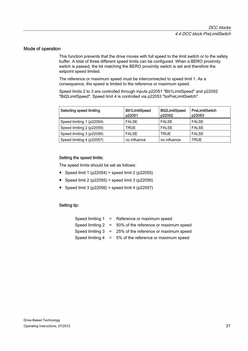
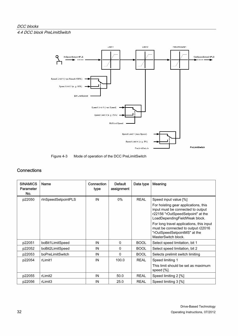
Mode of operation This function prevents that the drive moves with full speed to the limit switch or to the safety buffer. A total of three different speed limits can be configured. When a BERO proximity switch is passed, the bit matching the BERO proximity switch is set and therefore the setpoint speed limited.
The reference or maximum speed must be interconnected to speed limit 1. As a consequence, the speed is limited to the reference or maximum speed.
Speed limits 2 to 3 are controlled through inputs p22051 "Bit1LimitSpeed" and p22052 "Bit2LimitSpeed". Speed limit 4 is controlled via p22053 "boPreLimitSwitch".
Selecting speed limiting Bit1LimitSpeed
p22051 Bit2LimitSpeed p22052
PreLimitSwitch p22053
Speed limiting 1 (p22054) FALSE FALSE FALSE Speed limiting 2 (p22055) TRUE FALSE FALSE Speed limiting 3 (p22056) FALSE TRUE FALSE Speed limiting 4 (p22057) no influence no influence TRUE
Setting the speed limits:
The speed limits should be set as follows:
● Speed limit 1 (p22054) > speed limit 2 (p22055)
● Speed limit 2 (p22055) > speed limit 3 (p22056)
● Speed limit 3 (p22056) > speed limit 4 (p22057)
Setting tip:
Speed limiting 1 = Reference or maximum speed Speed limiting 2 = 50% of the reference or maximum speed Speed limiting 3 = 25% of the reference or maximum speed Speed limiting 4 = 5% of the reference or maximum speed
DCC blocks 4.4 DCC block PreLimitSwitch
Drive-Based Technology 32 Operating Instructions, 07/2012
Figure 4-3 Mode of operation of the DCC PreLimitSwitch
Connections
SINAMICS Parameter
No.
Name Connection type
Default assignment
Data type Meaning
p22050 rInSpeedSetpointPLS IN 0% REAL Speed input value [%] For hoisting gear applications, this input must be connected to output r22156 "rOutSpeedSetpoint" at the LoadDependingFieldWeak block. For long travel applications, this input must be connected to output r22016 "rOutSpeedSetpointMS" at the MasterSwitch block.
p22051 boBit1LimitSpeed IN 0 BOOL Select speed limitation, bit 1 p22052 boBit2LimitSpeed IN 0 BOOL Select speed limitation, bit 2 p22053 boPreLimitSwitch IN 0 BOOL Selects prelimit switch limiting p22054 rLimit1 IN 100.0 REAL Speed limiting 1
This limit should be set as maximum speed [%].
p22055 rLimit2 IN 50.0 REAL Speed limiting 2 [%] p22056 rLimit3 IN 25.0 REAL Speed limiting 3 [%]
DCC blocks 4.5 DCC block OverSpeed
Drive-Based Technology Operating Instructions, 07/2012 33
SINAMICS Parameter
No.
Name Connection type
Default assignment
Data type Meaning
p22057 rLimit4 IN 5.0 REAL Speed limiting 4 [%] r22058 rOutSpeedSetpointPLS OUT 0.0 REAL Speed output value [%]
The output must be connected to SINAMICS parameter p1070[0].
4.5 DCC block OverSpeed
Symbol
Brief description Using the DCC block OverSpeed, the overspeed can be monitored or a setpoint-actual value deviation can be identified.
Mode of operation
Note
The overspeed can also be directly handled in the SINAMICS; see function diagram 8010 in the SINAMICS S 120/150 List Manual (Ref. [2]).
Using this function, the actual speed can be monitored for an overspeed condition and a setpoint-actual value deviation detected.
A limit is defined for the setpoint-actual value deviation. If the actual speed exceeds this limit for the parameterized delay time p22040 "rDelayTime", then output r22041 "boOverSpeed" is set. This limit is the sum of the speed setpoint p22030 "SpeedSetpoint" and the offset p22039 "rOffset". The setpoint-actual value monitoring is activated using input p22038 "boEnableSetpointActualMonitoring".

DCC blocks 4.5 DCC block OverSpeed
Drive-Based Technology 34 Operating Instructions, 07/2012
The overspeed detection is implemented in the software for various speeds (field weakening operation and rated speed). If the specified offset (p22039 "rOffset") is exceeded for one of the two speeds for longer than the parameterized delay time, then this is signaled using output r22041 "boOverSpeed".
If the drive is in the field-weakening range, the actual speed is compared with the setpoint speed from the load-dependent field weakening p22034 "rAfterRampGenSpeed". If the actual speed is greater than the setpoint speed from the load-dependent field weakening plus the configured permissible deviation, then an overspeed condition is identified and is output at the block output.
The speed setpoint of the load-dependent field weakening is only used as comparison value if the drive is in the field-weakening range and field-weakening operation has been enabled for the drive. The comparison value of the load-dependent field weakening is used until the determined load is reset.
The overspeed monitoring is sent from SINAMICS via PROFIBUS in the application status word 1, bit 3. In SINAMICS, the signal is connected to the onboard I/O by means of BICO technology, see the table below. The SIMATIC S7 is connected to the SINAMICS CU onboard I/Os via a wire connection, reads in this signal and evaluates the signal status.
Output r22041 "boOverSpeed" is reset using parameter p22037 "boReset".
The p22037 "boReset" parameter should be connected with the r2138.7 "Acknowledge fault" parameter. The r22041 "boOverSpeed" output parameter for PROFIBUS DP and for I/O should be connected with the p2082[3] "application_status_word_1, bit 3" parameter and the p746 "Digital output 16" parameter, respectively.
Table 4- 2 Interconnection of the overspeed signal
Drives Terminal CU output Hoist 1 X130.07 DO 16
DCC blocks 4.5 DCC block OverSpeed
Drive-Based Technology Operating Instructions, 07/2012 35
Figure 4-4 DCC block OverSpeed, variable "boEnableSetpointActualMonitoring" = FALSE
Note
The rated speed must be input in the unit [rpm] at input p22032 "rRatedSpeed".
The reference or maximum speed must be connected in unit [rpm] with display parameter r2700 at input p22033 "rReferenceSpeed".
The block does not work correctly otherwise.
DCC blocks 4.5 DCC block OverSpeed
Drive-Based Technology 36 Operating Instructions, 07/2012
Figure 4-5 DCC block OverSpeed, variable "boEnableSetpointActualMonitoring" = TRUE
DCC blocks 4.5 DCC block OverSpeed
Drive-Based Technology Operating Instructions, 07/2012 37
Connections
SINAMICS parameter
number
Name Connection type
Default assignment
Data type Meaning
p22030 rSpeedSetpoint IN 0% REAL Setpoint speed [%] The input must be connected to SINAMICS parameter r0062.
p22031 rActualSpeed IN 0% REAL Actual drive speed [%] The input must be connected to SINAMICS parameter r0063.
p22032 rRatedSpeed IN 1500.0 REAL Rated speed [rpm] p22033 rReferenceSpeed IN 0% REAL Reference or maximum speed [rpm]
The input must be connected to SINAMICS parameter r2700.
p22034 rAfterRampGenSpeed IN 0% REAL Speed setpoint from the load-dependent field weakening [%]. The input must be connected to output r22159 "rAddSetpointSpeedAfterPLI" of the LoadDependingFieldWeak block.
p22035 boEnableFieldWeak IN 0 BOOL Field weakening active The input must be connected to output r22158 "boOutEnableFieldWeak" of the LoadDependingFieldWeak block.
p22036 boResetLoadCurrent IN 0 BOOL Load is reset from the load-dependent field weakening.
p22037 boReset IN 0 BOOL Reset the "boOverSpeed" output. The input must be connected with the SINAMICS r2138.7 "Acknowledge fault" parameter.
p22038 boEnableSetpointActualMon
IN 0 BOOL Activation of the setpoint-actual value monitoring.
p22039 rOffset IN 10.0 REAL Offset input [%] p22040 rDelayTime IN 250.0 REAL Delay time in [ms] r22041 boOverSpeed OUT 0 BOOL Overspeed active
- PROFIBUS DP: p2082[3] - I/O: p746

DCC blocks 4.6 DCC block CurrentDistribution
Drive-Based Technology 38 Operating Instructions, 07/2012
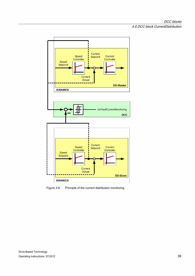
4.6 DCC block CurrentDistribution
Symbol
Short description The currents of the master and slave are monitored using the DCC block CurrentDistribution. An error message is generated if a deviation is exceeded.
Mode of operation
Note
This block is only required for synchronous operation or master-slave applications. In these applications, the block must be activated in the execution system (p21000[n]). For all other applications, the block must be deactivated in the execution system (p21000[n]).
This function can be used for master-slave operation or synchronous operation. The block monitors that the total current of both drives is distributed evenly. However, for crane applications this is not always the case.
In synchronous operation, the current setpoint is monitored for the two drives. In master-slave operation, the current actual value between the two drives is monitored; refer to the following diagram.
If the difference of the setpoint currents of both drives exceeds the configured values for deviation and duration, then output r22037 "boFaultCurrentMonitoring" is set.
NOTICE The reference current from SINAMICS from display parameter r2702 must be connected at input p22035 "rReferenceCurrent".
DCC blocks 4.6 DCC block CurrentDistribution
Drive-Based Technology Operating Instructions, 07/2012 39
Figure 4-6 Principle of the current distribution monitoring
DCC blocks 4.6 DCC block CurrentDistribution
Drive-Based Technology 40 Operating Instructions, 07/2012
Connections
SINAMICS Parameter
No.
Name Connection type
Default assignment
Data type Meaning
p22090 rMasterCurrent IN 0% REAL Master current setpoint [%] In synchronous operation, the input must be connected with the master SINAMICS parameter r0077. In master-slave operation, the input must be connected with the master SINAMICS parameter r0078.
p22091 rSlaveCurrent IN 0% REAL Slave current setpoint [%] In synchronous operation, the input must be connected with the slave SINAMICS parameter r0077. In master-slave operation, the input must be connected with the slave SINAMICS parameter r0078.
p22092 boEnableCurrentMon IN 0 BOOL Enables the current comparison monitoring
p22093 rDelayTime IN 20.0 REAL Delay time [ms] If a deviation occurs between the master and slave current, the output r22097 "boFaultCurrentMonitoring" is only set if the delay time has expired.
p22094 rParameterLimit IN 10.0 REAL Deviation threshold [%] The master and the slave current are subtracted and then compared with the deviation threshold.
p22095 rReferenceCurrent IN 0% REAL Reference current [A] The input must be connected to SINAMICS parameter r2702.
p22096 boMasterSlaveOrSynchOperation
IN 0 BOOL Operating mode for master-slave or synchronous operation Current distribution is only monitored in master-slave operation or in synchronous operation.
r22097 boFaultCurrentMonitoring OUT 0 BOOL Error message if the difference of the current setpoints of both drives exceeds the configured values for deviation and time.
r22098 rCurrentDifference OUT 0.0 REAL Actual result of the subtraction between master and slave [A]

DCC blocks 4.7 DCC block LoadDependingFieldWeak
Drive-Based Technology Operating Instructions, 07/2012 41
4.7 DCC block LoadDependingFieldWeak
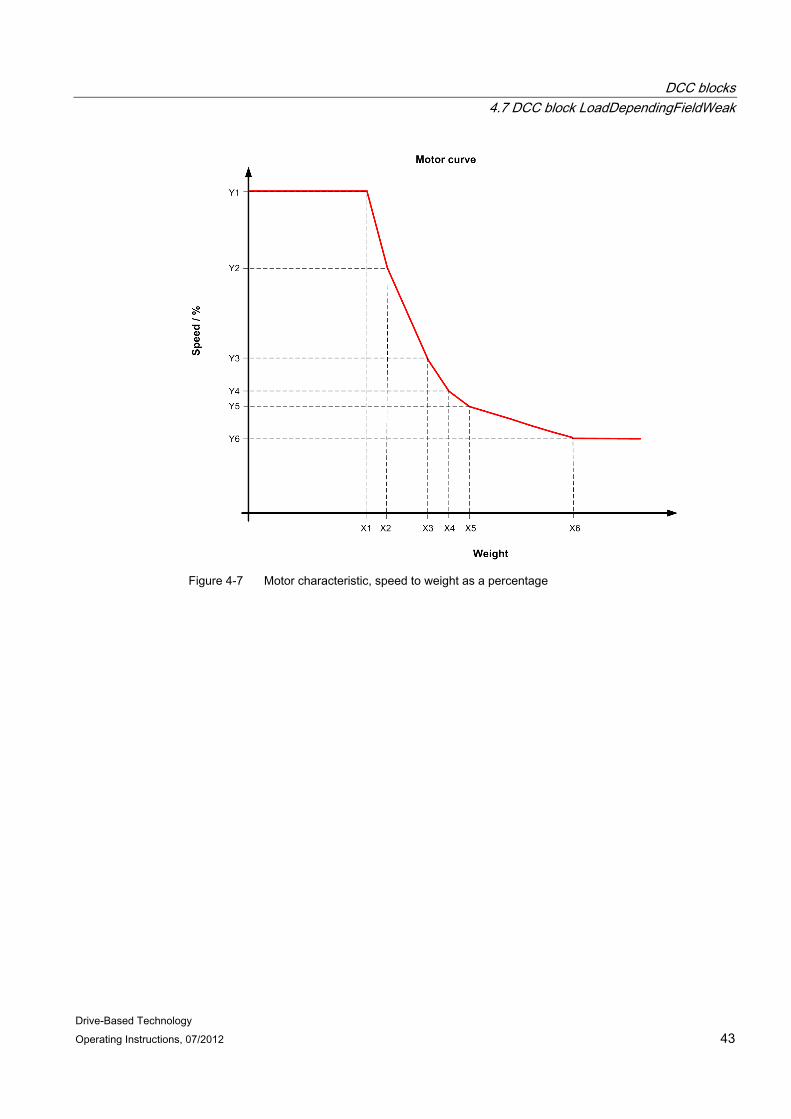
Symbol
Brief description For closed-loop control drives – in various operating situations – an attempt is made to increase the speed above the rated speed.
Using the LoadDependingFieldWeak DCC block, a supplementary speed setpoint is calculated dependent on the load. This speed increase for partial loads above the rated speed is required for cranes to increase the handling capacity. This is implemented using the motor characteristic that should be saved.
Note
This block is only required for hoisting gear applications. In hoisting gear applications, the block must be activated in the execution system (p21000[n]). For all other applications, the block must be deactivated in the execution system (p21000[n]).
Mode of operation When field weakening is selected, e.g. from the master switch, then depending on the load, the permissible speed setpoint is given as speed limit in the setpoint input.
DCC blocks 4.7 DCC block LoadDependingFieldWeak
Drive-Based Technology 42 Operating Instructions, 07/2012
When traveling at constant rated speed, the load actual value is determined from the torque. The maximum speed setpoint must be available at the block input; further, the actual speed must have approximately reached the rated speed and field weakening must have been enabled. This state must be pending for the time parameterized in p22161 "rDetectionConstMove" after which the torque calculation is started. The input at the p22161 parameter is limited to minimum 100 ms in order to reliably detect a constant speed. When there are sufficient measuring points, the measurement is stopped and an arithmetic mean value is generated from these points. There must be at least 25 measuring points in order to generate a mean value. To calculate the load, the frictional torque is subtracted from this total torque and when lowering, an efficiency correction is applied. After the stationary load actual value has been calculated, depending on the determined torque, the permissible speed setpoint for constant power P = PN for field weakening is generated (using the motor characteristic, implemented as parameterizable 6 point polygon function). The permissible speed setpoint after the measurement is used as speed limit for the setpoint input.
The determined load is only reset at standstill, i.e. the drive must be stationary, parameter p22133 "boNoStandStill" is not set (FALSE).
After this, the load can be reset with a rising positive edge at parameter p22141 "boResetLoadTorque".
WARNING This setting should only be carried out by qualified personnel. Particular attention must be paid to the reduced breakdown torque of the motor in the field weakening range. An appropriate safety margin must be added to the data provided by the machine manufacturer.
WARNING The rated speed in unit [rpm] must be entered at input p22135 "rRatedSpeed" and the reference or maximum speed (p22136 "rReferenceSpeed") must be connected to SINAMICS display parameter r2700.
The block does not work correctly otherwise.
DCC blocks 4.7 DCC block LoadDependingFieldWeak
Drive-Based Technology Operating Instructions, 07/2012 43
Figure 4-7 Motor characteristic, speed to weight as a percentage
DCC blocks 4.7 DCC block LoadDependingFieldWeak
Drive-Based Technology 44 Operating Instructions, 07/2012
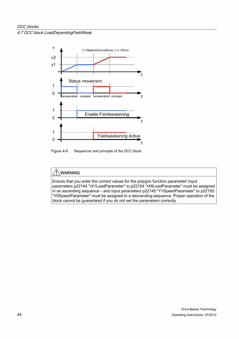
Figure 4-8 Sequencer and principle of the DCC block
WARNING Ensure that you enter the correct values for the polygon function parameter! Input parameters p22144 "rX1LoadParameter" to p22154 "rX6LoadParameter" must be assigned in an ascending sequence – and input parameters p22145 "Y1SpeedParameter" to p22155 "Y6SpeedParameter" must be assigned in a descending sequence. Proper operation of the block cannot be guaranteed if you do not set the parameters correctly.
DCC blocks 4.7 DCC block LoadDependingFieldWeak
Drive-Based Technology Operating Instructions, 07/2012 45
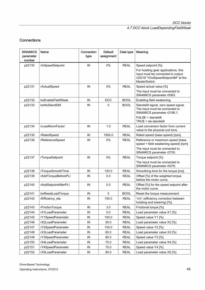
Connections
SINAMICS parameter
number
Name Connection type
Default assignment
Data type Meaning
p22130 rInSpeedSetpoint IN 0% REAL Speed setpoint [%] For hoisting gear applications, this input must be connected to output r22016 "rOutSpeedSetpointM" at the MasterSwitch.
p22131 rActualSpeed IN 0% REAL Speed actual value [%] The input must be connected to SINAMICS parameter r0063.
p22132 boEnableFieldWeak IN DCC BOOL Enabling field weakening. p22133 boNoStandStill IN 0 BOOL Standstill signal, zero speed signal.
The input must be connected to SINAMICS parameter r2199.1. FALSE = standstill TRUE = no standstill
p22134 rLoadNormFactor IN 1.0 REAL Load conversion factor from current value to the physical unit tons.
p22135 rRatedSpeed IN 1500.0 REAL Rated speed (base speed) [rpm]. p22136 rReferenceSpeed IN 0% REAL Reference or maximum speed (base
speed + field weakening speed) [rpm]. The input must be connected to SINAMICS parameter r2700.
p22137 rTorqueSetpoint IN 0% REAL Torque setpoint [%] The input must be connected to SINAMICS parameter r0079.
p22138 rTorqueSmoothTime IN 120.0 REAL Smoothing time for the torque [ms]. p22139 rAddTorqueBeforePLI IN 0.0 REAL Offset [%] of the weighted torque
before the motor curve. p22140 rAddSetpointAfterPLI IN 0.0 REAL Offset [%] for the speed setpoint after
the motor curve. p22141 boResetLoadTorque IN 0 BOOL Reset the torque measurement p22142 rEfficiency_eta IN 100.0 REAL 1/η2; (efficiency correction between
hoisting and lowering) [%]. p22143 rFrictionTorque IN 3.0 REAL Frictional torque [%] p22144 rX1LoadParameter IN 0.0 REAL Load parameter value X1 [%] p22145 rY1SpeedParameter IN 100.0 REAL Speed value Y1 [%] p22146 rX2LoadParameter IN 50.0 REAL Load parameter value X2 [%] p22147 rY2SpeedParameter IN 100.0 REAL Speed value Y2 [%] p22148 rX3LoadParameter IN 60.0 REAL Load parameter value X3 [%] p22149 rY3SpeedParameter IN 80.0 REAL Speed value Y3 [%] p22150 rX4LoadParameter IN 70.0 REAL Load parameter value X4 [%] p22151 rY4SpeedParameter IN 70.0 REAL Speed value Y4 [%] p22152 rX5LoadParameter IN 80.0 REAL Load parameter value X5 [%]
DCC blocks 4.7 DCC block LoadDependingFieldWeak
Drive-Based Technology 46 Operating Instructions, 07/2012
SINAMICS parameter
number
Name Connection type
Default assignment
Data type Meaning
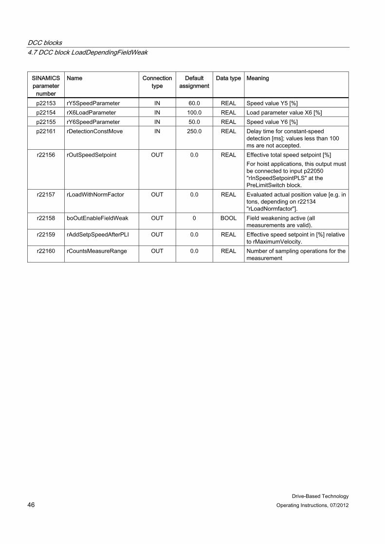
p22153 rY5SpeedParameter IN 60.0 REAL Speed value Y5 [%] p22154 rX6LoadParameter IN 100.0 REAL Load parameter value X6 [%] p22155 rY6SpeedParameter IN 50.0 REAL Speed value Y6 [%] p22161 rDetectionConstMove IN 250.0 REAL Delay time for constant-speed
detection [ms]; values less than 100 ms are not accepted.
r22156 rOutSpeedSetpoint OUT 0.0 REAL Effective total speed setpoint [%] For hoist applications, this output must be connected to input p22050 "rInSpeedSetpointPLS" at the PreLimitSwitch block.
r22157 rLoadWithNormFactor OUT 0.0 REAL Evaluated actual position value [e.g. in tons, depending on r22134 "rLoadNormfactor"].
r22158 boOutEnableFieldWeak OUT 0 BOOL Field weakening active (all measurements are valid).
r22159 rAddSetpSpeedAfterPLI OUT 0.0 REAL Effective speed setpoint in [%] relative to rMaximumVelocity.
r22160 rCountsMeasureRange OUT 0.0 REAL Number of sampling operations for the measurement

Drive-Based Technology Operating Instructions, 07/2012 47
Communication 5
The drive can be controlled via terminals (I/O) or via PROFIBUS DP. For control via terminals, only the on-board terminals are required. For PROFIBUS DP communication between the higher-level SIMATIC S7 control and the drive, a maximum of 16 process data each are provided for the send and receive directions.
5.1 Task distribution The following list provides an overview of task distribution between SIMATIC S7 and SINAMICS.
SIMATIC S7 (if available)
● Crane overview
● I/O signal processing
● Safety-related monitoring
● Setpoint and control commands for main drives
SINAMICS
● Crane technology in DCC
● Ramp-function generator
● Closed-loop speed control
● Closed-loop current control
● Monitoring, if required
● Positioning, if required
● Brake control (combined with StartPulse in a standard application)
● Safety Integrated function, if necessary
● Master-slave closed-loop torque control, if necessary
Prerequisites In order to establish disturbance-free communication between the two parties, the reference data in SIMATIC and SINAMICS modules must be identically configured. The reference data must be normalized to the maximum data.
Communication 5.1 Task distribution
Drive-Based Technology 48 Operating Instructions, 07/2012
The following parameters are involved in the modules:
SIMATIC
● Reference speed
● Reference voltage
● Reference current
● Reference torque
SINAMICS
● p2000 = r2700 = reference speed reference frequency ( ≈ p1082 = maximum speed)
● p2001 = r2701 = reference voltage
● p2002 = r2702 = reference current
● p2003 = r2703 = reference torque
Note
All reference data must be normalized to their maximum value: • nmax = nreference = 100% = nrated + nFw
(maximum speed = reference speed = rated speed + field weakening speed) • Imax = Ireference = 100% = Irated + Ioverload
(maximum current = reference current = rated current + overload current) • Mmax = Mreference = 100% = Mrated + Moverload
(maximum torque = reference torque = rated torque + overload torque)
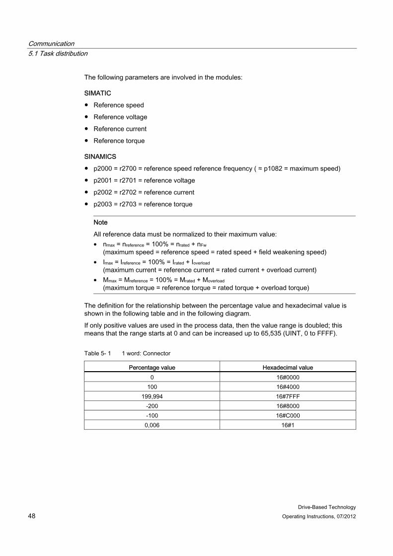
The definition for the relationship between the percentage value and hexadecimal value is shown in the following table and in the following diagram.
If only positive values are used in the process data, then the value range is doubled; this means that the range starts at 0 and can be increased up to 65,535 (UINT, 0 to FFFF).
Table 5- 1 1 word: Connector
Percentage value Hexadecimal value 0 16#0000
100 16#4000 199,994 16#7FFF
-200 16#8000 -100 16#C000 0,006 16#1

Communication 5.2 Configuring the PROFIBUS connection
Drive-Based Technology Operating Instructions, 07/2012 49
Figure 5-1 Representing the value range of a word
5.2 Configuring the PROFIBUS connection The type and baud rate of the communication between SIMATIC and SINAMICS is configured in the HW-Configuration. Communication uses PROFIBUS.
Communication between SIMATIC and SINAMICS is implemented using a telegram defined for Drive-Based Technology (16 process data on the send side / 16 process data on the receive side). The standard telegram is extended to a free telegram (999) with 16 process data each on the send and receive sides.
Note
Parameter p0922 must be set to a free telegram (999) when configuring the system. With the execution of the script from the selection screen, the communication interconnection is automatically set to the correct values for the telegram data words, see Section Standard application, SingleAxis (Page 90).
The address ranges for communications between SIMATIC and SINAMICS should be configured as follows. These addresses can be adapted in the HW-Configuration.
Table 5- 2 Address ranges of the drives
Drives Address a range, I/O (peripherals) in bytes Hoist 1 300 … 331
Trolley 1 400 … 431 Long travel 1 500 … 531 Long travel 2 550 … 581

Communication 5.2 Configuring the PROFIBUS connection
Drive-Based Technology 50 Operating Instructions, 07/2012
Scripts are available in the standard project. They can be used to automatically execute all the communication interconnections in SINAMICS; also see Chapter Communication SIMATIC → SINAMICS (Page 52) and Communication SINAMICS → SIMATIC (Page 54). In the standard application, the script (Com_S7_IO) is executed automatically from a selection screen, see Section Standard application, SingleAxis (Page 90).
The script file (e.g. Com_S7_IO) is started with Accept and execute. The script file is run through and all of the necessary communication connections are generated.
Note • The script file should be executed offline. The changes then have to be downloaded to
the drive. • The script file to establish communication with the S7 control has the same name for all
main drives (hoist, trolley, gantry) - namely "Com_S7_IO". • The reference data should be checked and adapted in every script file. • The torque setpoint (p1503) of the slave (e.g. Gantry_2) must be linked to the torque
setpoint (r0079) of the master (e.g. Gantry_1) because it is not executed in the script. • All connections, which are established by the script, are listed in the STARTER output
window. • Further, a report can be generated. The report can be saved on the hard disk.

Communication 5.2 Configuring the PROFIBUS connection
Drive-Based Technology Operating Instructions, 07/2012 51
Figure 5-2 Accepting and executing the script file
You can see the actual status of the script execution in the output window.
Communication 5.2 Configuring the PROFIBUS connection
Drive-Based Technology 52 Operating Instructions, 07/2012
5.2.1 Communication SIMATIC → SINAMICS
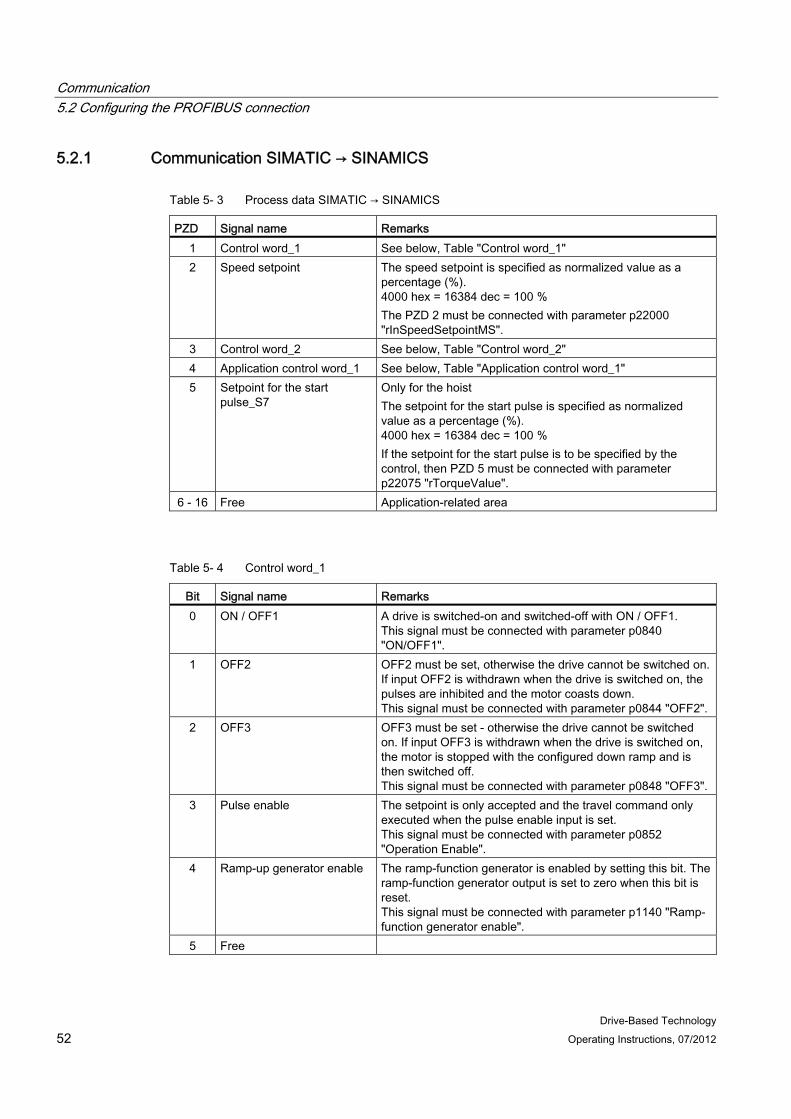
Table 5- 3 Process data SIMATIC → SINAMICS
PZD Signal name Remarks 1 Control word_1 See below, Table "Control word_1" 2 Speed setpoint The speed setpoint is specified as normalized value as a
percentage (%). 4000 hex = 16384 dec = 100 % The PZD 2 must be connected with parameter p22000 "rInSpeedSetpointMS".
3 Control word_2 See below, Table "Control word_2" 4 Application control word_1 See below, Table "Application control word_1" 5 Setpoint for the start
pulse_S7 Only for the hoist The setpoint for the start pulse is specified as normalized value as a percentage (%). 4000 hex = 16384 dec = 100 % If the setpoint for the start pulse is to be specified by the control, then PZD 5 must be connected with parameter p22075 "rTorqueValue".
6 - 16 Free Application-related area
Table 5- 4 Control word_1
Bit Signal name Remarks 0 ON / OFF1 A drive is switched-on and switched-off with ON / OFF1.
This signal must be connected with parameter p0840 "ON/OFF1".
1 OFF2 OFF2 must be set, otherwise the drive cannot be switched on. If input OFF2 is withdrawn when the drive is switched on, the pulses are inhibited and the motor coasts down. This signal must be connected with parameter p0844 "OFF2".
2 OFF3 OFF3 must be set - otherwise the drive cannot be switched on. If input OFF3 is withdrawn when the drive is switched on, the motor is stopped with the configured down ramp and is then switched off. This signal must be connected with parameter p0848 "OFF3".
3 Pulse enable The setpoint is only accepted and the travel command only executed when the pulse enable input is set. This signal must be connected with parameter p0852 "Operation Enable".
4 Ramp-up generator enable The ramp-function generator is enabled by setting this bit. The ramp-function generator output is set to zero when this bit is reset. This signal must be connected with parameter p1140 "Ramp-function generator enable".
5 Free
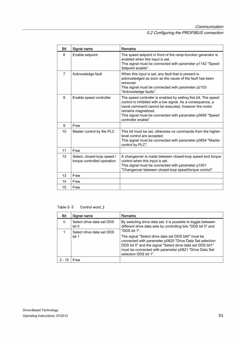
Communication 5.2 Configuring the PROFIBUS connection
Drive-Based Technology Operating Instructions, 07/2012 53
Bit Signal name Remarks 6 Enable setpoint The speed setpoint in front of the ramp-function generator is
enabled when this input is set. This signal must be connected with parameter p1142 "Speed Setpoint enable".
7 Acknowledge fault When this input is set, any fault that is present is acknowledged as soon as the cause of the fault has been removed. This signal must be connected with parameter p2103 "Acknowledge faults".
8 Enable speed controller The speed controller is enabled by setting this bit. The speed control is inhibited with a low signal. As a consequence, a travel command cannot be executed, however the motor remains magnetized. This signal must be connected with parameter p0856 "Speed controller enable".
9 Free 10 Master control by the PLC This bit must be set, otherwise no commands from the higher-
level control are accepted. This signal must be connected with parameter p0854 "Master control by PLC".
11 Free 12 Select, closed-loop speed /
torque controlled operation A changeover is made between closed-loop speed and torque control when this input is set. This signal must be connected with parameter p1501 "Changeover between closed-loop speed/torque control".
13 Free 14 Free 15 Free
Table 5- 5 Control word_2
Bit Signal name Remarks 0 Select drive data set DDS
bit 0 1 Select drive data set DDS
bit 1
By selecting drive data set, it is possible to toggle between different drive data sets by controlling bits "DDS bit 0" and "DDS bit 1". The signal "Select drive data set DDS bit0" must be connected with parameter p0820 "Drive Data Set selection DDS bit 0" and the signal "Select drive data set DDS bit1" must be connected with parameter p0821 "Drive Data Set selection DDS bit 1".
2 - 15 Free
Communication 5.2 Configuring the PROFIBUS connection
Drive-Based Technology 54 Operating Instructions, 07/2012
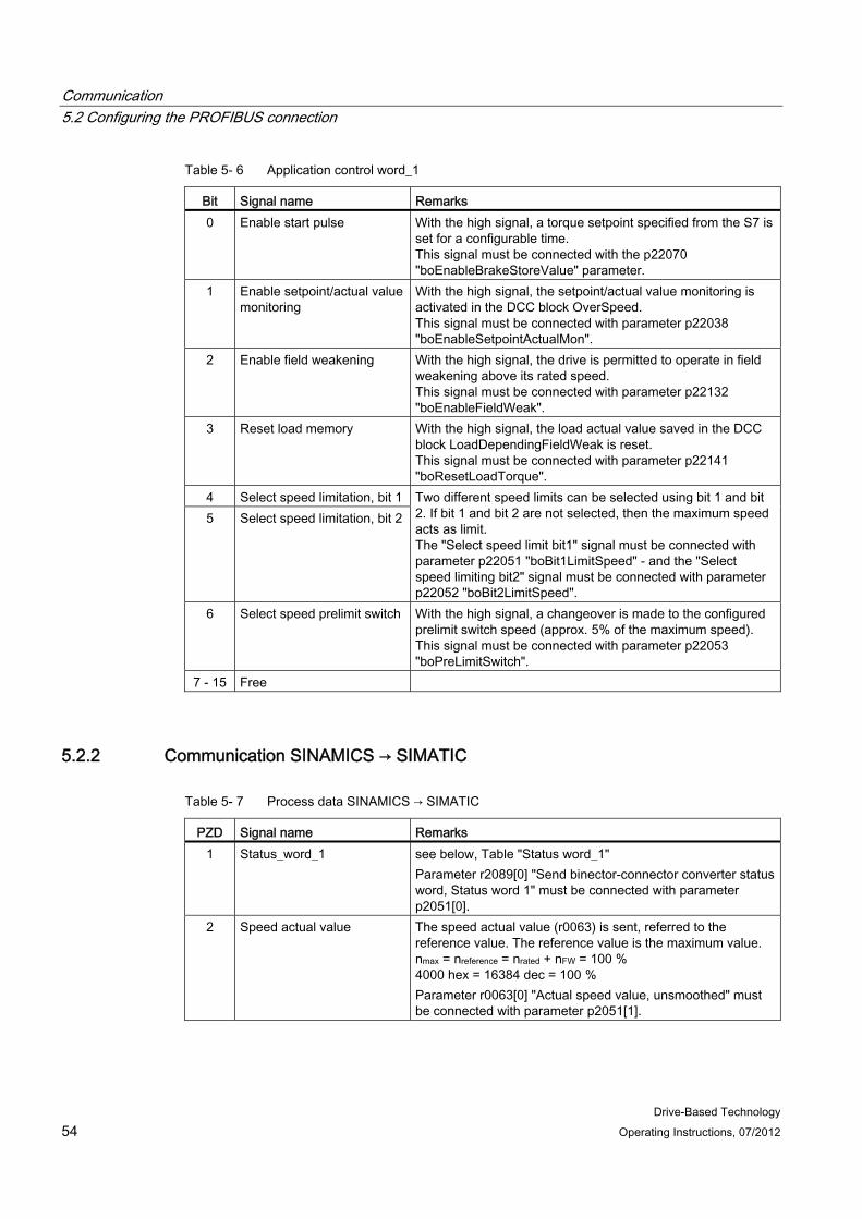
Table 5- 6 Application control word_1
Bit Signal name Remarks 0 Enable start pulse With the high signal, a torque setpoint specified from the S7 is
set for a configurable time. This signal must be connected with the p22070 "boEnableBrakeStoreValue" parameter.
1 Enable setpoint/actual value monitoring
With the high signal, the setpoint/actual value monitoring is activated in the DCC block OverSpeed. This signal must be connected with parameter p22038 "boEnableSetpointActualMon".
2 Enable field weakening With the high signal, the drive is permitted to operate in field weakening above its rated speed. This signal must be connected with parameter p22132 "boEnableFieldWeak".
3 Reset load memory With the high signal, the load actual value saved in the DCC block LoadDependingFieldWeak is reset. This signal must be connected with parameter p22141 "boResetLoadTorque".
4 Select speed limitation, bit 1 5 Select speed limitation, bit 2
Two different speed limits can be selected using bit 1 and bit 2. If bit 1 and bit 2 are not selected, then the maximum speed acts as limit. The "Select speed limit bit1" signal must be connected with parameter p22051 "boBit1LimitSpeed" - and the "Select speed limiting bit2" signal must be connected with parameter p22052 "boBit2LimitSpeed".
6 Select speed prelimit switch With the high signal, a changeover is made to the configured prelimit switch speed (approx. 5% of the maximum speed). This signal must be connected with parameter p22053 "boPreLimitSwitch".
7 - 15 Free
5.2.2 Communication SINAMICS → SIMATIC
Table 5- 7 Process data SINAMICS → SIMATIC
PZD Signal name Remarks 1 Status_word_1 see below, Table "Status word_1"
Parameter r2089[0] "Send binector-connector converter status word, Status word 1" must be connected with parameter p2051[0].
2 Speed actual value The speed actual value (r0063) is sent, referred to the reference value. The reference value is the maximum value. nmax = nreference = nrated + nFW = 100 % 4000 hex = 16384 dec = 100 % Parameter r0063[0] "Actual speed value, unsmoothed" must be connected with parameter p2051[1].
Communication 5.2 Configuring the PROFIBUS connection
Drive-Based Technology Operating Instructions, 07/2012 55
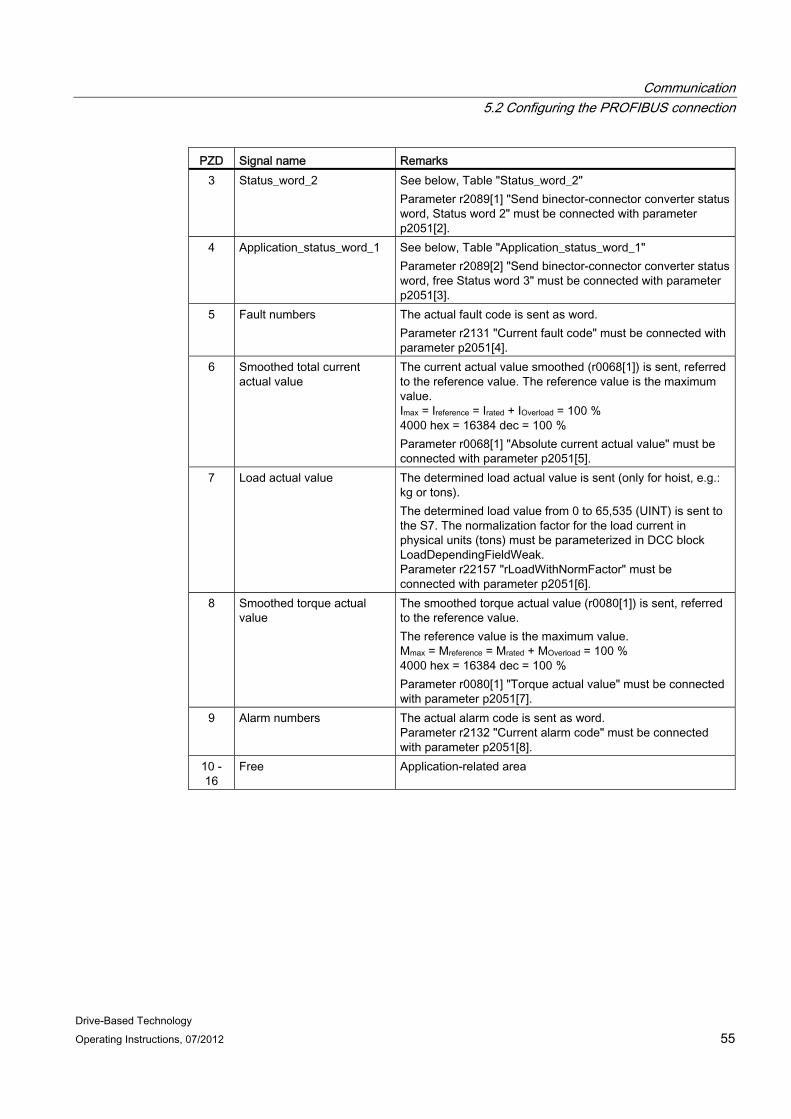
PZD Signal name Remarks 3 Status_word_2 See below, Table "Status_word_2"
Parameter r2089[1] "Send binector-connector converter status word, Status word 2" must be connected with parameter p2051[2].
4 Application_status_word_1 See below, Table "Application_status_word_1" Parameter r2089[2] "Send binector-connector converter status word, free Status word 3" must be connected with parameter p2051[3].
5 Fault numbers The actual fault code is sent as word. Parameter r2131 "Current fault code" must be connected with parameter p2051[4].
6 Smoothed total current actual value
The current actual value smoothed (r0068[1]) is sent, referred to the reference value. The reference value is the maximum value. Imax = Ireference = Irated + IOverload = 100 % 4000 hex = 16384 dec = 100 % Parameter r0068[1] "Absolute current actual value" must be connected with parameter p2051[5].
7 Load actual value The determined load actual value is sent (only for hoist, e.g.: kg or tons). The determined load value from 0 to 65,535 (UINT) is sent to the S7. The normalization factor for the load current in physical units (tons) must be parameterized in DCC block LoadDependingFieldWeak. Parameter r22157 "rLoadWithNormFactor" must be connected with parameter p2051[6].
8 Smoothed torque actual value
The smoothed torque actual value (r0080[1]) is sent, referred to the reference value. The reference value is the maximum value. Mmax = Mreference = Mrated + MOverload = 100 % 4000 hex = 16384 dec = 100 % Parameter r0080[1] "Torque actual value" must be connected with parameter p2051[7].
9 Alarm numbers The actual alarm code is sent as word. Parameter r2132 "Current alarm code" must be connected with parameter p2051[8].
10 - 16
Free Application-related area

Communication 5.2 Configuring the PROFIBUS connection
Drive-Based Technology 56 Operating Instructions, 07/2012
Table 5- 8 Status_word_1
Bit Signal name Remarks 0 Ready to be switched on If a high signal is available at the bit, then this means that the
power supply is switched on and the electronics has been initialized. Parameter r0899 bit0 "Ready for switching on" must be connected with the binector-connector converter in parameter p2080[0].
1 Ready If a high signal is available at the bit, then this means that voltage is connected to the Line Module. Parameter r0899 bit1 "Ready for operation" must be connected with the binector-connector converter in parameter p2080[1].
2 Operation enable If a high signal is available at the bit, then this means that the electronics and the pulses have been enabled and the drive accelerates up to the setpoint that has been entered. Parameter r0899 bit2 "Ready for operation" must be connected with the binector-connector converter in parameter p2080[2].
3 Fault active If a high signal is present at the bit, this indicates that the drive has a fault and is therefore non-operational. After acknowledgment and after the cause has been successfully removed, the drive goes into the switch-on inhibit state. Parameter r2139 bit3 "Fault present" must be connected with the binector-connector converter in parameter p2080[3].
4 Coasting down active (OFF2)
If a high signal is available at the bit, then this signifies that no OFF2 is active. Parameter r899 bit4 "No coasting active" must be connected with the binector-connector converter in parameter p2080[4].
5 Quick stop active (OFF3) If a high signal is available at the bit, then this signifies that no OFF3 is active. Parameter r0899 bit5 "No quick stop active" must be connected with the binector-connector converter in parameter p2080[5].
6 Switch on inhibit If a high signal is available at the bit, then this signifies that a restart is only possible using OFF1 followed by ON. Parameter r0899 bit6 "Switching on inhibited active" must be connected with binector-connector converter in parameter p2080[6].
7 Alarm active If a high signal is available at the bit, then this means that the drive is in operation again and acknowledgment is not required. Parameter r2139 bit7 "Alarm present" must be connected with the binector-connector converter in parameter p2080[7].
8 Speed setpoint-actual value deviation within the tolerance range
If a high signal is available at the bit, then this means that the actual value is within the tolerance range. Parameter r2197 bit7 "Speed setp – act val deviation in tolerance t_off" must be connected with the binector-connector converter in parameter p2080[8].
9 Control request to PLC If a high signal is available at the bit, then this means that the automation system is requested to accept master control. Parameter r0899 bit9 "Control requested" must be connected with the binector-connector converter in parameter p2080[9].

Communication 5.2 Configuring the PROFIBUS connection
Drive-Based Technology Operating Instructions, 07/2012 57
Bit Signal name Remarks 10 f or n comparison value
reached or exceeded If a high signal is available at the bit, then this means that the f or n comparison value has been reached or exceeded. Parameter r2199 bit1 "f or n comparison value reached or exceeded" must be connected with the binector-connector converter in parameter p2080[10].
11 I, M or P limit reached or exceeded
If a high signal is available at the bit, then this means that the I, M or P limit has not been reached or was exceeded. Parameter r1407 bit7 "Torque limit reached" must be connected with the binector-connector converter in parameter p2080[11].
12 Holding brake open If a high signal is available at the bit, then this means that the holding brake is activated. Parameter r0899 bit12 "Holding brake open" must be connected with the binector-connector converter in parameter p2080[12].
13 No motor overtemperature alarm
If a high signal is present at the bit, this indicates that the ramp-function generator is active.
14 n_act >= 0 If a high signal is available at the bit, this means that the speed setpoint ≥ 0. Parameter r2197 bit3 "n_act >=0" must be connected with the binector-connector converter in parameter p2080[14].
15 No alarm, thermal power unit overload
If a high signal is present at the bit, this indicates that there is no alarm due to thermal overload of the drive converter. With a low signal an alarm is present due to thermal overload of the power unit. Parameter r2135 bit15 "Alarm power unit terminal overload" must be connected with the binector-connector converter in parameter p2080[15].
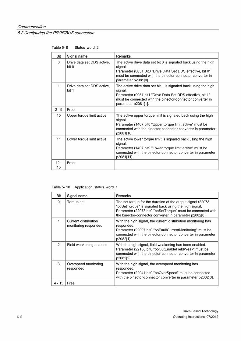
Communication 5.2 Configuring the PROFIBUS connection
Drive-Based Technology 58 Operating Instructions, 07/2012
Table 5- 9 Status_word_2
Bit Signal name Remarks 0 Drive data set DDS active,
bit 0 The active drive data set bit 0 is signaled back using the high signal. Parameter r0051 Bit0 "Drive Data Set DDS effective, bit 0" must be connected with the binector-connector converter in parameter p2081[0].
1 Drive data set DDS active, bit 1
The active drive data set bit 1 is signaled back using the high signal. Parameter r0051 bit1 "Drive Data Set DDS effective, bit 1" must be connected with the binector-connector converter in parameter p2081[1].
2 - 9 Free 10 Upper torque limit active The active upper torque limit is signaled back using the high
signal. Parameter r1407 bit8 "Upper torque limit active" must be connected with the binector-connector converter in parameter p2081[10].
11 Lower torque limit active The active lower torque limit is signaled back using the high signal. Parameter r1407 bit9 "Lower torque limit active" must be connected with the binector-connector converter in parameter p2081[11].
12 - 15
Free
Table 5- 10 Application_status_word_1
Bit Signal name Remarks 0 Torque set The set torque for the duration of the output signal r22078
"boSetTorque" is signaled back using the high signal. Parameter r22078 bit0 "boSetTorque" must be connected with the binector-connector converter in parameter p2082[0].
1 Current distribution monitoring responded
With the high signal, the current distribution monitoring has responded. Parameter r22097 bit0 "boFaultCurrentMonitoring" must be connected with the binector-connector converter in parameter p2082[1].
2 Field weakening enabled With the high signal, field weakening has been enabled. Parameter r22158 bit0 "boOutEnableFieldWeak" must be connected with the binector-connector converter in parameter p2082[2].
3 Overspeed monitoring responded
With the high signal, the overspeed monitoring has responded. Parameter r22041 bit0 "boOverSpeed" must be connected with the binector-connector converter in parameter p2082[3].
4 - 15 Free
Communication 5.3 Configuring the I/O connection
Drive-Based Technology Operating Instructions, 07/2012 59
5.3 Configuring the I/O connection A solution with terminals (analog input, digital inputs and digital outputs) is shown in the following for basic single-axis crane operation without using a higher-level control.
Note
With the execution of the script from the selection screen, the I/O connection automatically interconnects to the correct parameters; refer to the table below and Section Standard application, SingleAxis (Page 90).
Note
When using multi-motor operation for gantry or trolley, each motor is monitored using its own circuit breaker. For each drive group, the monitoring function is connected in series, i.e. for a voltage of 24 V everything is OK - and for a voltage of 0 V, then the monitoring function has responded.
The monitoring signal is connected to the onboard digital inputs of the SINAMICS Control Unit. To shut down the relevant drive group, this monitoring signal is connected to OFF2. As soon as the monitoring function trips the circuit breaker, then this drive group is shut down with OFF2. • Example of a distributed single-axis solution with 1 CU for each axis:
SINAMICS CU1 digital input 10 (X121.10) group Trolley_1 SINAMICS CU2 digital input 10 (X121.10) group Trolley_2 SINAMICS CU3 digital input 10 (X121.10) group Gantry_1 SINAMICS CU4 digital input 10 (X121.10) group Gantry_2

Communication 5.3 Configuring the I/O connection
Drive-Based Technology 60 Operating Instructions, 07/2012
Table 5- 11 Pre-assignment of the analog input, digital inputs and digital outputs of the CU310-2
Terminal Signal name Remarks DI0 = X121.1
Speed specification 1; positive direction
Speed specification 1; positive direction of rotation specification. Control Unit p21501 = r722.0 Drive Object p22002 = r722.0 Master switch deflected in the positive direction.
DI1 = X121.2
Speed specification 1; negative direction
Speed specification 1; negative direction of rotation specification. Control Unit p21502 = r722.1 Drive Object p22003 = r722.1 Master switch deflected in the negative direction.
DI2 = X121.3
Speed specification 2 / free
Speed specification 2 / free Control Unit p21503 = r722.2
DI3 = X121.4
Speed specification 3 / free
Speed specification 3 / free Control Unit p21504 = r722.3
DI8 = X121.7
Speed specification 4 / free
Speed specification 4 / free Control Unit p21505 = r722.4
DI9 = X121.8
ON / OFF1 The drive is switched on and off using ON / OFF1. Drive Object p840 = r722.8
DI10 = X121.10
OFF2 OFF2 must be set, otherwise the drive cannot be switched on. If input OFF2 is withdrawn when the drive is switched on, the pulses must be inhibited and the motor coasts down. Drive Object p844 = r722.9
DI11 = X121.11
Acknowledge fault When this input is set, any pending fault is acknowledged as soon as the fault cause has been remedied. Drive Object p2103 = r722.11
DI12 = X131.01
Enable start pulse With a high signal, a constant torque setpoint or a torque setpoint issued from the S7 as a function of the load is set for a configurable time. Drive Object p22070 = r722.12
DI13 = X131.02
Enable setpoint / actual value monitoring
A high signal activates the setpoint / actual value monitoring in the DCC_OverSpeed block. Drive Object p22038 = r722.13
DO14 = X131.04
Fault active If a high signal is present at the bit, this indicates that the drive has a fault and is therefore non-operational. The drive switches to "switch-on inhibited" once the fault has been acknowledged and the cause has been remedied. Control Unit p744 = r2139.3
DO15 = X131.05
Open brake A high signal present at the bit indicates that the brake must be opened. Control Unit p745 = r899.12
AI0+ = X131.07 AI0- = X131.08
Analog master switch setpoint
The master switch setpoint is specified in the range from 0 to 10 V. Drive Object p22000 = r752
DI16 = X120.03
Free / EP terminal This input is used as EP terminal for activated Safety Integrated Basic Functions.
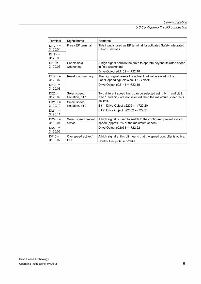
Communication 5.3 Configuring the I/O connection
Drive-Based Technology Operating Instructions, 07/2012 61
Terminal Signal name Remarks DI17 + = X120.04 DI17 - = X120.05
Free / EP terminal This input is used as EP terminal for activated Safety Integrated Basic Functions.
DI18 = X120.06
Enable field weakening
A high signal permits the drive to operate beyond its rated speed in field weakening. Drive Object p22132 = r722.18
DI19 + = X120.07 DI19 - = X120.08
Reset load memory The high signal resets the actual load value saved in the LoadDependingFieldWeak DCC block. Drive Object p22141 = r722.19
DI20 = X120.09
Select speed limitation, bit 1
DI21 + = X120.10 DI21 - = X120.11
Select speed limitation, bit 2
Two different speed limits can be selected using bit 1 and bit 2. If bit 1 and bit 2 are not selected, then the maximum speed acts as limit. Bit 1: Drive Object p22051 = r722.20 Bit 2: Drive Object p22052 = r722.21
DI22 + = X130.01 DI22 - = X130.02
Select speed prelimit switch
A high signal is used to switch to the configured prelimit switch speed (approx. 5% of the maximum speed). Drive Object p22053 = r722.22
D016 = X130.07
Overspeed active / free
A high signal at this bit means that the speed controller is active. Control Unit p746 = r22041

Communication 5.3 Configuring the I/O connection
Drive-Based Technology 62 Operating Instructions, 07/2012
Figure 5-3 CU310-2 pre-assignment in standard applications
Drive-Based Technology Operating Instructions, 07/2012 63
Commissioning 6
NOTICE The polarity rules must be paid attention to:
Hoisting gear: Hoisting speed is POSITIVE, with ascending position values. Lowering speed is NEGATIVE, with descending position values.
Long travel: Travel to the right, POSITIVE speed with ascending position values. Travel to the left, NEGATIVE speed with descending position values.
Trolley: Travel towards the ship, POSITIVE speed with ascending position values. Travel towards the shore, NEGATIVE speed with descending position values.
6.1 General information The scope of delivery is described in the chapter titled System overview (Page 7). The CD contains several archived projects (ZIP format) with a SINAMICS CU310-2 and the cranes DCC blocks.
Using a project from the CD
1. Copy the archived project from the CD to the hard disk.
2. Dearchive the project (unzip).
3. Import the project into STARTER using XML import.
4. The imported project can be used as basis for the application.
Transferring DCC blocks into the customer application project
If a customer application project already exists, then you can take the cranes DCC blocks from one of the projects archived on the CD. To do so, proceed as follows:
1. Execute the steps 1. to 3. as described above.
2. Open both of the projects in STARTER (the project imported into STARTER and the customer application project).
3. Copy the blocks of the imported project into the Windows clipboard.
4. Insert the DCC blocks into the customer application project.
5. This means that these DCC blocks are now also available in the customer application project.
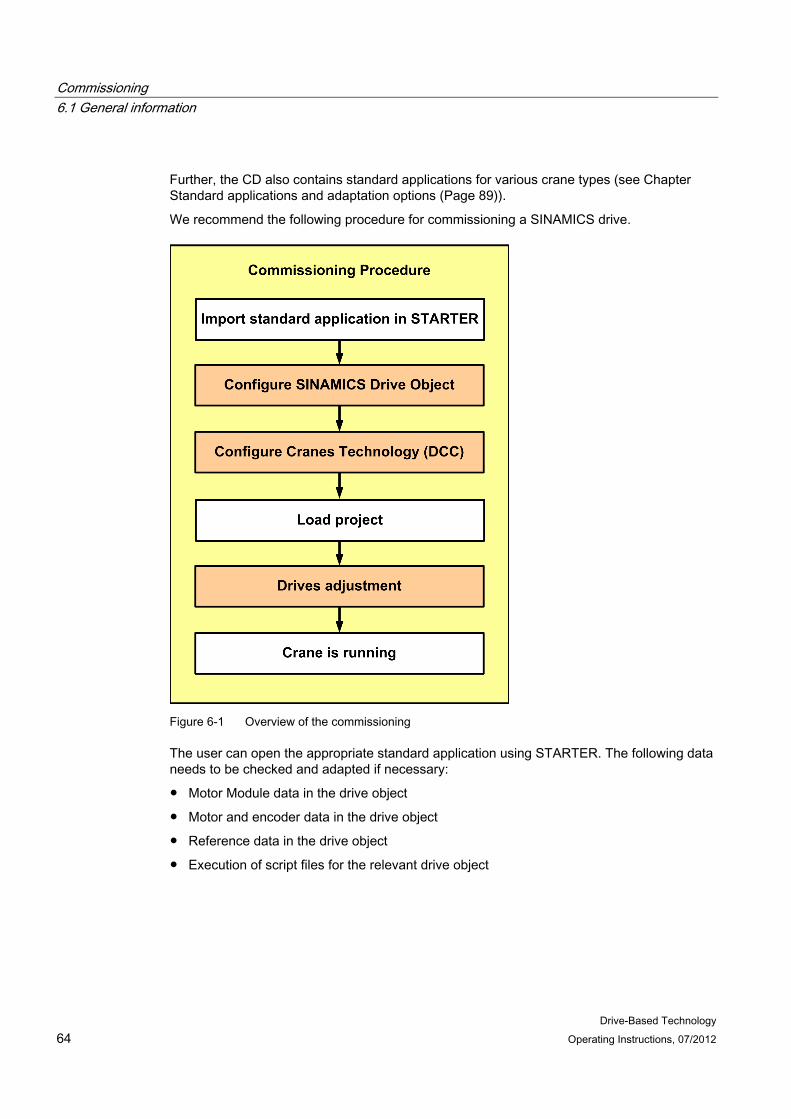
Commissioning 6.1 General information
Drive-Based Technology 64 Operating Instructions, 07/2012
Further, the CD also contains standard applications for various crane types (see Chapter Standard applications and adaptation options (Page 89)).
We recommend the following procedure for commissioning a SINAMICS drive.
Figure 6-1 Overview of the commissioning
The user can open the appropriate standard application using STARTER. The following data needs to be checked and adapted if necessary:
● Motor Module data in the drive object
● Motor and encoder data in the drive object
● Reference data in the drive object
● Execution of script files for the relevant drive object
Commissioning 6.1 General information
Drive-Based Technology Operating Instructions, 07/2012 65
Crane-specific technologies (DCC):
● Adaptation of the master switch curve in the DCC block MasterSwitch
● Adaptation of the torque-speed characteristic in the DCC block LoadDependingFieldWeak
● Adaptation of the rated speed (rRatedSpeed) in the DCC blocks
● Adaptation of the prelimit switch speed in the DCC block PreLimitSwitch
● etc.
The adapted standard application must be loaded to the CompactFlash (CF) card, once all necessary settings have been successfully made.
When commissioning has been completed, a RAM to ROM store operation must be performed to ensure that the user program is copied to the CF card for retentive storage.
Communication via PROFIBUS between the S7 and SINAMICS is preconfigured in the standard projects; further information can be found in the chapter titled Communication (Page 47). The commissioning procedure is described below.
Before users start the commissioning procedure, they should ensure that the motor data and encoder data in the SINAMICS drive object match those of their real system. This should be checked in the configuration data of the SINAMICS drive object (refer to following diagram). The user also has to ensure that the reference speed (p2000) and maximum speed (p1082) for SINAMICS match the reference speed and maximum speed for SIMATIC. In SINAMICS, the reference parameters p2000 to p2003 must be checked.

Commissioning 6.2 Controlling the crane taking the PROFIdrive profile into account
Drive-Based Technology 66 Operating Instructions, 07/2012
Figure 6-2 Configuration file DO Hoist_1
6.2 Controlling the crane taking the PROFIdrive profile into account The control of the drive is now subsequently shown in an example; for more detailed information see Ref. [6]
6.2.1 Switch on the drive The drive is switched on as follows:
● Select OFF2 and OFF3.
OFF2 and OFF3 checkback signals are output after one program cycle. "Ready to power up" is also output. These signals switch OFF1. After one further cycle, "Ready" is signaled.
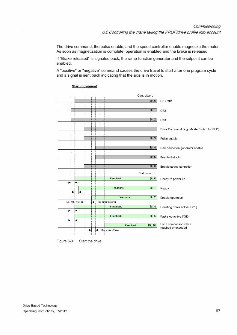
Commissioning 6.2 Controlling the crane taking the PROFIdrive profile into account
Drive-Based Technology Operating Instructions, 07/2012 67
The drive command, the pulse enable, and the speed controller enable magnetize the motor. As soon as magnetization is complete, operation is enabled and the brake is released.
If "Brake released" is signaled back, the ramp-function generator and the setpoint can be enabled.
A "positive" or "negative" command causes the drive travel to start after one program cycle and a signal is sent back indicating that the axis is in motion.
Figure 6-3 Start the drive
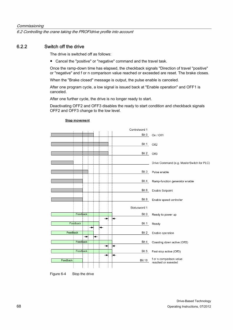
Commissioning 6.2 Controlling the crane taking the PROFIdrive profile into account
Drive-Based Technology 68 Operating Instructions, 07/2012
6.2.2 Switch off the drive The drive is switched off as follows:
● Cancel the "positive" or "negative" command and the travel task.
Once the ramp-down time has elapsed, the checkback signals "Direction of travel "positive" or "negative" and f or n comparison value reached or exceeded are reset. The brake closes.
When the "Brake closed" message is output, the pulse enable is canceled.
After one program cycle, a low signal is issued back at "Enable operation" and OFF1 is canceled.
After one further cycle, the drive is no longer ready to start.
Deactivating OFF2 and OFF3 disables the ready to start condition and checkback signals OFF2 and OFF3 change to the low level.
Figure 6-4 Stop the drive
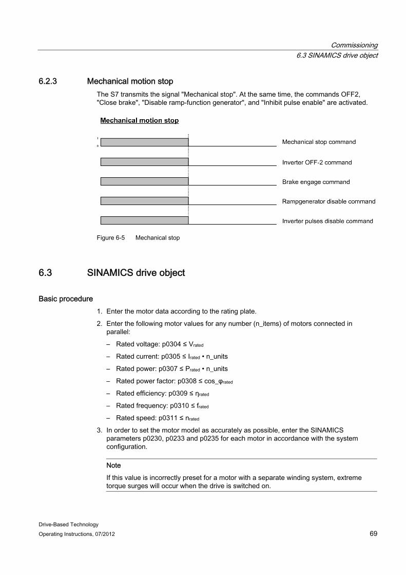
Commissioning 6.3 SINAMICS drive object
Drive-Based Technology Operating Instructions, 07/2012 69
6.2.3 Mechanical motion stop The S7 transmits the signal "Mechanical stop". At the same time, the commands OFF2, "Close brake", "Disable ramp-function generator", and "Inhibit pulse enable" are activated.
Figure 6-5 Mechanical stop
6.3 SINAMICS drive object
Basic procedure 1. Enter the motor data according to the rating plate.
2. Enter the following motor values for any number (n_items) of motors connected in parallel:
– Rated voltage: p0304 ≤ Vrated
– Rated current: p0305 ≤ Irated • n_units
– Rated power: p0307 ≤ Prated • n_units
– Rated power factor: p0308 ≤ cos_φrated
– Rated efficiency: p0309 ≤ ηrated
– Rated frequency: p0310 ≤ frated
– Rated speed: p0311 ≤ nrated
3. In order to set the motor model as accurately as possible, enter the SINAMICS parameters p0230, p0233 and p0235 for each motor in accordance with the system configuration.
Note
If this value is incorrectly preset for a motor with a separate winding system, extreme torque surges will occur when the drive is switched on.
Commissioning 6.3 SINAMICS drive object
Drive-Based Technology 70 Operating Instructions, 07/2012
4. Determine the total cable resistance (Motor Module to motor) for each motor and enter the result in SINAMICS parameter p0352.
5. Enter the motor series reactor (if installed) in SINAMICS parameter p0353.
Stationary measurement After having checked all of the prerequisites, carry out a stationary measurement in SINAMICS for each Motor Module (i.e. hoist, gantry, trolley, etc.).
Note
Prior to the standstill measurement: After having entered all data, go online to the corresponding drive object and verify the data specified above or adapt it accordingly. Initially set SINAMICS parameter p0340 to a value of 2. After parameter p0340 has returned to 0, it must be set again to a value of 3.
The following values are determined in the stationary measurement:
● Equivalent circuit diagram data
● Stator resistance
● Leakage inductances
● IGBT forward voltage or compensation for the IGBT interlock times
Tips after the stationary measurement ● In operation, check the flux actual value:
– With the correct rating plate data and successfully set MOT ID, the actual flux value (r0084) is 100% and below field weakening.
– Check over the complete speed range up to field weakening, e.g. while accelerating.
● If a rotating measurement cannot be performed, if necessary, manually correct the magnetizing current and magnetizing inductance:
– Correct the rated magnetizing current (p0320) until an actual flux value (r0084) of 100% is reached over the entire speed range up to field weakening. If the rated magnetizing current is still not correct, then deviations will be visible - especially in the range up to 30% nrated.
– If the drive can be rotated freely (without load or with only slight load), the correct value of the magnetizing current (r0029) can be read-out when operating in the speed range 60% nrated up to 80% nrated and entered in p0320.
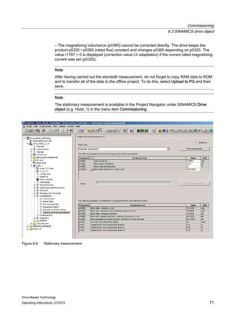
Commissioning 6.3 SINAMICS drive object
Drive-Based Technology Operating Instructions, 07/2012 71
– The magnetizing inductance (p0360) cannot be corrected directly. The drive keeps the product p0320 • p0360 (rated flux) constant and changes p0360 depending on p0320. The value r1787 = 0 is displayed (correction value Lh adaptation) if the correct rated magnetizing current was set (p0320).
Note
After having carried out the standstill measurement, do not forget to copy RAM data to ROM and to transfer all of the data to the offline project. To do this, select Upload to PG and then save.
Note
The stationary measurement is available in the Project Navigator under SINAMICS Drive object (e.g. Hoist_1) in the menu item Commissioning.
Figure 6-6 Stationary measurement
Commissioning 6.3 SINAMICS drive object
Drive-Based Technology 72 Operating Instructions, 07/2012
Checking the direction of rotation After the stationary measurement has been successfully completed, then the direction of rotation should first be checked. If the motors have still not been installed, the SINAMICS control panel should be used to check the direction of rotation. Otherwise, the direction of rotation should be checked via the PLC (S7) or via terminals (I/O) - i.e. when the motor is rotating in the positive direction. The encoder must then supply positive values.
If it is no longer possible to interchange the phases, the direction must be reversed in SINAMICS using parameter p1821. Please note that for several drive data sets with different motors, this change must be made for all of the data sets involved.
Note
You can find more detailed information about using the control panel in Chapter 4.3 "Using the operator control panel" in document Ref. [4].
Rotating measurement The rotating measurement with speed controller optimization should then be carried out. The rotating measurement function should only be initiated if the motor can freely rotate. Otherwise, it is not permissible that this function is executed.
The following values are determined in the rotating measurement:
● The magnetizing characteristic is measured
● The magnetizing current is measured
● The speed controller is optimized
● The acceleration pre-control is set
● The ratio between the total moment of inertia and the motor is set
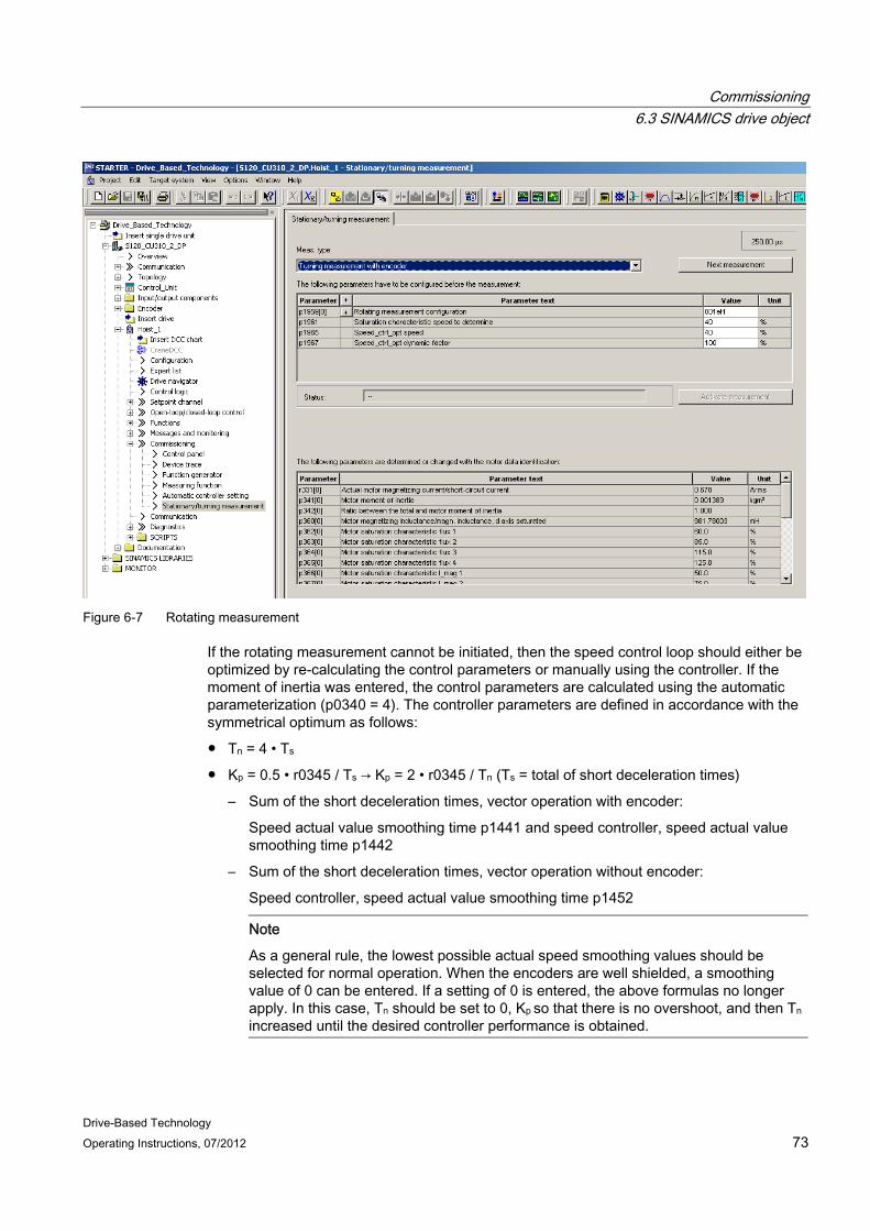
Commissioning 6.3 SINAMICS drive object
Drive-Based Technology Operating Instructions, 07/2012 73
Figure 6-7 Rotating measurement
If the rotating measurement cannot be initiated, then the speed control loop should either be optimized by re-calculating the control parameters or manually using the controller. If the moment of inertia was entered, the control parameters are calculated using the automatic parameterization (p0340 = 4). The controller parameters are defined in accordance with the symmetrical optimum as follows:
● Tn = 4 • Ts
● Kp = 0.5 • r0345 / Ts → Kp = 2 • r0345 / Tn (Ts = total of short deceleration times)
– Sum of the short deceleration times, vector operation with encoder:
Speed actual value smoothing time p1441 and speed controller, speed actual value smoothing time p1442
– Sum of the short deceleration times, vector operation without encoder:
Speed controller, speed actual value smoothing time p1452
Note
As a general rule, the lowest possible actual speed smoothing values should be selected for normal operation. When the encoders are well shielded, a smoothing value of 0 can be entered. If a setting of 0 is entered, the above formulas no longer apply. In this case, Tn should be set to 0, Kp so that there is no overshoot, and then Tn increased until the desired controller performance is obtained.
Commissioning 6.3 SINAMICS drive object
Drive-Based Technology 74 Operating Instructions, 07/2012
If oscillation develops with these settings, reduce the speed controller gain Kp manually. Actual speed value smoothing can also be increased (standard procedure for gearless or high-frequency torsional oscillation) and the controller calculation performed again because this value is also used to calculate Kp and Tn.
The following relationships apply for optimization:
● If Kp is increased, the controller becomes faster and overshoot is increased.
● If Tn is reduced, the controller also becomes faster and the overshoot is also increased.
When setting the speed control manually, the simplest approach is to first define the dynamic response via Kp (and actual speed value smoothing), so that the integral time can be subsequently reduced as much as possible. When doing this, the closed-loop control must also remain stable in the field-weakening range.
Reducing the controller gain will generally dampen any oscillations in the closed-loop speed control. Another possible option is to increase the smoothing time in p1452. However, the accuracy of the control will diminish if smoothing is set too high. The integral output of the speed controller can be monitored via r1482 and the limited controller output (torque setpoint) via r1508.
Tips regarding speed optimization ● Adjusting the switchover from current model ("open-loop controlled") to voltage model
("closed-loop controlled"):
– p1752 = 300 [rpm]: Switchover speed
– p1756 = 20 [%]: Hysteresis
These two values have proven themselves to be useful in practice, however, they can be adapted as required.
● Complete commissioning by operating the drive across the entire speed range and checking that operation is smooth in order to exclude universal shaft/gear problems.
● The trolleys excite the natural resonance of the crane structure when the speed changes quickly. This is not in the control loop of the trolley; but represents the reference system.
– To prevent damage caused by excited oscillations: Kp low, Tn high, adaptation
– The integrator has a tendency towards saturation which leads to overshoot of the end position and subsequent retraction
Commissioning 6.4 Cranes DCC blocks
Drive-Based Technology Operating Instructions, 07/2012 75
● Acceleration precontrol for the known mass
Problem: Mass varies with/without load (e.g. container); precontrol with approx. 80 – 90%
With precontrol, relieve the I component as far as possible: Also observe r1482; r1481; r0080 and r0078 in the trace.
– The precontrol function is available in the Project Navigator under the SINAMICS Drive object (e.g. Hoist_1) in the menu item Open-loop/closed-loop control > speed setpoint filter > Precontrol
– The precontrol function can be set accordingly using p0342 Ratio of total/motor moment of inertia and p1496 Acceleration precontrol scaling
● Setpoint/actual value smoothing – balancing
– Actual value smoothing should be kept to a minimum; high values increase overshoot - setpoint smoothing provides a more constant velocity due to the motion profile (master switch setpoint)
6.4 Cranes DCC blocks The DCC blocks must be configured for the various tasks; also see Chapter DCC blocks (Page 21).
● MasterSwitch block
The master switch curve must be configured if the DCC_MasterSwitch block is used.
● PreLimitSwitch block
The speed limits must be adapted in the DCC_PreLimitSwitch block.
● CurrentDistribution block (relevant for trolley and hoisting gear)
The deceleration time and the parameter threshold must be adapted as required in the DCC_CurrentDistribution block.
● StartPulse block (only relevant for hoist)
The I component of the speed controller is saved in the DCC_StartPulse block when the "Close brake" command is issued. When the "Release brake" command is issued, the speed controller is set with this saved I component.
● LoadDependingFieldWeaking block (only relevant for hoist)
The load-dependent curve must be entered in the DCC_LoadDependingFieldWeaking block and the factors must be determined in the commissioning phase; refer to Function (DCC block) "Load-dependent field weakening" (Page 76).
● OverSpeed block
When required, the parameter threshold is adapted in the DCC_OverSpeed block in order to identify an overspeed condition.
Commissioning 6.5 Function (DCC block) "Load-dependent field weakening"
Drive-Based Technology 76 Operating Instructions, 07/2012
6.5 Function (DCC block) "Load-dependent field weakening" For closed-loop control drives – in various operating situations – an attempt is made to increase the speed above the rated speed. This is used, for example, for hoisting gear of cranes to increase the handling capacity.
However, the maximum speed in the rated speed range that can be achieved at rated flux is determined by the maximum permissible voltage. This means that an increase above this speed cannot be achieved by increasing the voltage; both for DC and also AC drives, this is only possible using field weakening.
However, with field weakening the available torque is reduced. This means that field weakening is only possible if also a reduced torque is demanded. For a hoisting gear, this is e.g. only possible for partial loads that are less than the rated load.
The permissible speed ω for the (maximum) rated power P = PN for this speed increase is determined using P = M • ω in the rated speed range at initially constant flux – dependent on the required torque.
In this case, the upper speed limit is the maximum permissible speed for the motor.
A measure for required load torque in the rated speed range is the current in the steady-state phase, which is directly proportional to load torque.
The DCC block calculates the steady-state (static) component of the torque, which must be provided for the prevailing torque from the total torque in the rated speed range. The total torque is then corrected to take into account the frictional torque, which then results in the torque that is available for the load.
For reasons of accuracy, the arithmetic mean value is used for the calculation. Further, dependent on the calculated torque, the permissible speed setpoint for field weakening for P = PN is generated using the motor power characteristic.
6.5.1 Theoretical basics and equations The steady-state load torque is calculated using the following torque equation.
Mmotor = Mload + Mfriction
Mmotor : Motor torque
Mload : Load torque (this is required)
Mfriction : Frictional torque
WARNING This setting should only be carried out by qualified personnel. Particular attention must be paid to the reduced breakdown torque of the motor in the field weakening range.
Add a safety margin to the data provided by the machine manufacturer.
Commissioning 6.5 Function (DCC block) "Load-dependent field weakening"
Drive-Based Technology Operating Instructions, 07/2012 77
6.5.2 Commissioning instructions
6.5.2.1 Generating the measured variables Sufficient measurements must be made in order to obtain a realistic value when determining the average torque in the constant speed phase.
The arithmetic average value is generated by integrating all of the values obtained in a measuring window in the constant speed phase.
This constant speed must be pending for the time parameterized in p22161 "rDetectionConstMove" after which the torque calculation is started. The input at the p22161 parameter is limited to minimum 100 ms in order to reliably detect a constant speed.
The number of measurements can be read-out in "rCountsMeasurRange".
For a new measurement, at standstill, the old measurement must be deleted (the measurement is deleted using a positive edge at "boResetLoadTorque"), otherwise, no new load and no new field weakening speed are determined. If the old measurement is not deleted, then the values last determined are available at the output of the DCC block.
For the hoisting direction, the following always applies:
● Acceleration must be POSITIVE (100% at the rated acceleration time).
● The actual speed value must be POSITIVE (100% at the field weakening speed).
● Current actual value (100% at the rated motor current) must be POSITIVE.
Note
If a new measurement is to be made, then it is absolutely necessary that a positive edge is applied to connection "boResetLoadTorque".
Commissioning 6.5 Function (DCC block) "Load-dependent field weakening"
Drive-Based Technology 78 Operating Instructions, 07/2012
Table 6- 1 Standard assignment of the setting connections before commissioning
Parameter number
Name Value Description
p22134 rLoadNormFactor 1.0 Adaptation factor to convert into a physical quantity The conversion is made using the formula: Load[t] = measured value * rLoadNormFactor + rAddTorqueBeforePLI
p22138 rTorqueSmoothTime 120 ms Smoothing time for the torque [ms] Rough order of magnitude: 0 ms – 200 ms
p22139 rAddTorqueBeforePLI 0.0 Offset to determine the load: Load[t] = measured value * rLoadNormFactor + rAddTorqueBeforePLI
p22142 rEfficiency_eta 100 % Adaptation factor (referred to the rated load) for the difference in efficiency when raising and lowering Rough order of magnitude: 110 % - 120 %
p22143 rFrictionTorque 0.0 % Frictional component (referred to the rated load) for the torque Rough order of magnitude: 1 % - 3 % This corresponds to the torque value to be compensated
p22161 rDetectionConstMove 250 ms Delay time for constant-speed detection [ms]; values less than 100 ms are not accepted
Note
The orders of magnitude listed in the above table are guide values only.
Table 6- 2 Important outputs of the DCC block for commissioning
Parameter number
Name Value Description
r22156 rOutSpeedSetpoint - Speed setpoint logically combined with the master switch setpoint r22157 rLoadWithNormFactor - Evaluated load actual value r22158 boOutEnableFieldWea
k - Enable field weakening
r22159 rAddSetpointAfterPLI % Supplementary speed setpoint with offset relative to "rReferenceSpeed" after motor curve
r22160 rCountsMeasureRange - Number of sampling operations for the measurement
Commissioning 6.5 Function (DCC block) "Load-dependent field weakening"
Drive-Based Technology Operating Instructions, 07/2012 79
6.5.2.2 Compensating the frictional torque Mmotor = Mload + Mfriction
Setting instructions
Note
If at all possible, perform the measurements with the motor in a warm state with warm gearbox oil.
1. Move the empty drum at constant rated speed (nrated) in the hoisting direction.
120 ms has proven itself as a good value for parameter p22138 "rTorqueSmoothTime". However, this value can be individually adapted.
2. In parameter r0079 "rTorqueSetpointTotal" read the frictional torque and convert the absolute value into a percentage, taking into account the reference torque in parameter p2003. The calculation is made according to the following formula: p22143 [%] = (r0079 [Nm] x 100 [%]) / (p2003 [Nm])
3. Repeat your measurement in the hoisting direction.
4. Enter the mean value (approx. 1 % to 3 %) into parameter p22143 "rFrictionTorque".
This means that the frictional current will be taken into account at the output, parameter r22157 "rLoadWithNormFactor".
6.5.2.3 Correcting the efficiency The efficiency correction is used to ensure that with the same load, the velocity when lowering is identical to the velocity when hoisting (raising). For hoisting and lowering, in order to determine the same load actual value at different current values, it is necessary to multiply the value present when lowering in the parameter r22157 "rLoadWithNormFactor" by the factor 1/η2.
The setting is made with parameter p22142 "rEfficiency_eta". Parameter r22157 "rLoadWithNormFactor" should neither change when hoisting nor when lowering.
As a result, the efficiency correction value will always be ≤ 100% for hoisting and ≥ 100 % for lowering. This will be illustrated in the following calculation as example.

Commissioning 6.5 Function (DCC block) "Load-dependent field weakening"
Drive-Based Technology 80 Operating Instructions, 07/2012
Example calculation Saved value with the rated load, hoisting: Parameter r22157 "rLoadWithNormFactorHoisting = 98 %
Saved value with the rated load, lowering: Parameter r22157 "rLoadWithNormFactorLowering = 82 %
Calculated value (rEfficiency_eta) = 119.51 %
Setting instructions Move the rated load in the hoisting direction and then in the lowering direction at constant rated speed (nrated motor), assuming rEfficiency_eta = 100% (default setting) – repeat this measurement several times. And note down the mean values of " rLoadWithNormFactorHoisting" and " rLoadWithNormFactorLowering". Calculate the rEfficiency_eta corresponding to the specified example.
Note
Apply a positive edge at input "boResetLoadTorque" after every measurement.
Check the settings by hoisting and lowering the rated load (up to the rated speed) several times. In so doing, parameter r22157 "rLoadWithNormFactor" should no longer change when hoisting and lowering. Adapt the factor in parameter p22142 "rEfficiency_eta" (approx. 115 %) to keep the change between hoisting and lowering as low as possible.
Note
When lowering, if a load higher than the actual load is determined, a higher value of "rLoadWithNormFactor" while lowering with respect to hoisting ensures that the drive is not overloaded when braking the load.
This setting is only necessary for the case where the load should be determined while lowering (e.g. when starting with lowering). For normal applications, it is sufficient if the determined load is only re-calculated again if the load has changed. Normally, this is only possible after the spreader has taken-up a new load. This means that the signals "Twistlocks open" and "Twistlocks closed" can be used to set a positive edge of the signal "boResetLoadCurrent". This allows the load to be recalculated.

Commissioning 6.5 Function (DCC block) "Load-dependent field weakening"
Drive-Based Technology Operating Instructions, 07/2012 81
6.5.2.4 Calculating the physical size of the load The determined load can be converted to a physical quantity (e.g. tons) using connections "rLoadNormFactor" and "rAddCurrentBeforePLI".
Calculation example:
When hoisting a rated load of 45 t, "rLoadWithNormFactor" indicates a value of 85 %.
A constant load can be added (e.g. in tons) using "rAddTorqueBeforePLI".
6.5.3 Criteria for enabling field weakening Field weakening is not enabled or is inhibited as long as parameter p22132 "boEnableFieldWeak" is set to false.
While field weakening is not enabled, the master switch setpoint is limited to the rated speed. As soon as field weakening is enabled (parameter r22158 "boOutEnableFieldWeak" = True), the master switch setpoint is limited to the calculated load-dependent speed setpoint.
The criteria to enable field weakening – dependent on the speed actual value and speed setpoint – are described in the following:
● The speed setpoint in parameter p22130 "rInSpeedSetpoint" is interrogated at the input of the DCC block for a value greater than 95% of the reference speed (parameter p22136 "rReferenceSpeed").
● The speed actual value in parameter p22131 "rActualSpeed" is interrogated at the input of the DCC block for a value greater than 90% of the rated speed (parameter p22135 "rRatedSpeed").
● The input in parameter p22132 "boEnableFieldWeak" must be set.
This constant speed must be pending for the time parameterized in p22161 "rDetectionConstMove" after which the torque calculation is started. The input at the p22161 parameter is limited to minimum 100 ms in order to reliably detect a constant speed.
Load determination is only started if the conditions mentioned above are fulfilled. As soon as this operation has been completed, field weakening is enabled and the speed setpoint is increased corresponding to the configured motor characteristic.
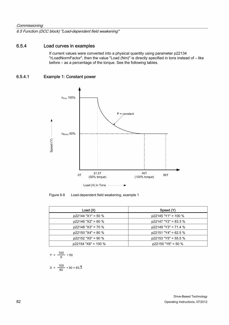
Commissioning 6.5 Function (DCC block) "Load-dependent field weakening"
Drive-Based Technology 82 Operating Instructions, 07/2012
6.5.4 Load curves in examples If current values were converted into a physical quantity using parameter p22134 "rLoadNormFactor", then the value "Load (Nm)" is directly specified in tons instead of – like before – as a percentage of the torque. See the following tables.
6.5.4.1 Example 1: Constant power
Figure 6-8 Load-dependent field weakening, example 1
Load (X) Speed (Y)
p22144 "X1" = 50 % p22145 "Y1" = 100 % p22146 "X2" = 60 % p22147 "Y2" = 83.3 % p22148 "X3" = 70 % p22149 "Y3" = 71.4 % p22150 "X4" = 80 % p22151 "Y4" = 62.5 % p22152 "X5" = 90 % p22153 "Y5" = 55.5 %
p22154 "X6" = 100 % p22155 "Y6" = 50 %
Commissioning 6.5 Function (DCC block) "Load-dependent field weakening"
Drive-Based Technology Operating Instructions, 07/2012 83
WARNING • If excessively high torque values occur during constant-velocity travel, then the speed
(Y2-Y5) must be reduced. • The initial points for load or speed (X1 or Y1) as well as end points X6 and Y6 are fixed.
The intermediate load points (X2-X5) can assume any values. The corresponding intermediate values for speed (Y2-Y5) are calculated according to the formula above.
• We recommend that the first points along the curve are selected close to one another as the speed is inversely proportional to the load.
• If a linearized motor curve is used, it must be ensured that the points along the motor curve (X1 to X6; Y1 to Y6) lie below the motor curve for constant power.
6.5.4.2 Example 2: Curve is specified (no constant power) This example is valid under the following conditions:
● It is not possible to utilize the motor power.
● The customer has supplied a load curve which specifies his technical requirements.
0 – 15 T → Speed 100 %
15 – 40 T → Speed, refer to the curve supplied by the customer 40 – 56 T → Speed 50 %
The current required to hoist 40 tons at rated speed (no field weakening) must first be determined. The current is directly proportional to the load. If, for a load of 40 tons, a current of 86% is measured, then for a 15 ton load the current should be 32%
The curve can be calculated using the following formula:
n: Speed Q: Load X: Constant Y: Constant
With the data used above:
equating to

Commissioning 6.5 Function (DCC block) "Load-dependent field weakening"
Drive-Based Technology 84 Operating Instructions, 07/2012
Result after inserting (constant): X = 2548.148151 and Y = 20.37037028
Figure 6-9 Load-dependent field weakening, example 2
Load (X) Speed (Y)
p22144 "X1" = 32 % p22145 "Y1" = 100 % p22146 X2" = 45 % p22147 "Y2" = 77.0 % p22148 "X3" = 55 % p22149 "Y3" = 66.7 % p22150 "X4" = 65 % p22151 "Y4" = 59.6 % p22152 "X5" = 76 % p22153 "Y5" = 53.9 % p22154 "X6" = 86 % p22155 "Y6" = 50.0 %
Commissioning 6.5 Function (DCC block) "Load-dependent field weakening"
Drive-Based Technology Operating Instructions, 07/2012 85
WARNING • If excessively high current values occur during constant-velocity travel, then the speed
(Y2-Y6) must be reduced. • The initial points for load or speed (X1 or Y1) as well as end points X6 and Y6 are fixed.
The intermediate load points (X2-X5) can assume any values. The corresponding intermediate values for speed (Y2-Y5) are calculated according to the formula above.
• We recommend that the first points along the curve are selected close to one another, as the speed is inversely proportional to the load and to the offset.
• If a linearized motor curve is used, it must be ensured that the points along the motor curve (X1 to X6; Y1 to Y6) lie below the motor curve for constant power.

Commissioning 6.6 The trace function
Drive-Based Technology 86 Operating Instructions, 07/2012
6.6 The trace function The trace function can be used to record measured values over a defined period depending on trigger conditions.
The trace function is parameterized and operated via the parameterization and commissioning tool STARTER.
Note
Please refer to the STARTER online help for more information about parameterizing and operation.
● Up to eight recording channels per recorder
● Device clock cycles of SINAMICS S120 trace for single traces and endless trace:
– 4 channels: 0.250 ms (Vector)
– 8 channels: 4 ms (Vector)
It is possible that time slice 4 ms may not be available due to the system property. In this case, the next higher time slice is used.
● Two independent trace recorders per Control Unit
● Endless trace
After the last trace parameters have been written to, the drive automatically starts again from the beginning with writing into the trace memory (ring buffer function).
● Triggering
– Without triggering (recording immediately after start)
– Triggering on signal - either signal edge or signal level
– Trigger delay and pretrigger possible
● STARTER parameterization and commissioning tool
– Automatic or adjustable scaling of display axes
– Signal measurement via cursor
● Adjustable trace cycle: Integer multiples of the basic sampling time
● Averaging the trace values
If a float value is recorded with a cycle which is slower than the device cycle, the values recorded will not be averaged. This is achieved using parameter p4724.
Parameter p4724[0...1] "Trace averaging in the time range" is set to "0" in the basic setting.
Indices "0" and "1" stand for the two trace recorders, each with eight channels. Parameter p4724 must be set to "1" if the values that have been recorded are to be averaged.
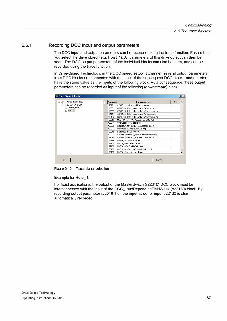
Commissioning 6.6 The trace function
Drive-Based Technology Operating Instructions, 07/2012 87
6.6.1 Recording DCC input and output parameters The DCC input and output parameters can be recorded using the trace function. Ensure that you select the drive object (e.g. Hoist_1). All parameters of this drive object can then be seen. The DCC output parameters of the individual blocks can also be seen, and can be recorded using the trace function.
In Drive-Based Technology, in the DCC speed setpoint channel, several output parameters from DCC blocks are connected with the input of the subsequent DCC block - and therefore have the same value as the inputs of the following block. As a consequence, these output parameters can be recorded as input of the following (downstream) block.
Figure 6-10 Trace signal selection
Example for Hoist_1:
For hoist applications, the output of the MasterSwitch (r22016) DCC block must be interconnected with the input of the DCC_LoadDependingFieldWeak (p22130) block. By recording output parameter r22016 then the input value for input p22130 is also automatically recorded.

Commissioning 6.6 The trace function
Drive-Based Technology 88 Operating Instructions, 07/2012

Drive-Based Technology Operating Instructions, 07/2012 89
Standard applications and adaptation options 7
The standard applications and adaptation options are described in this chapter. DCC chart expansion, data units, scaling data received from the control and changing a parameter type are described in the adaptation options. Delivery of the projects is described in the standard applications.
The following table lists the standard applications included in the scope of supply. These serve as a starting basis for Ready-to-Run as well as Ready-to-Apply applications. Users can copy the standard applications from the CD supplied to a hard disk. The project must then be dearchived (unzipped) and imported into the STARTER engineering tool using XML import.
Table 7- 1 Standard applications
Project Function module Number of axes
Control Master switch type
Control mode Control Unit
SingleAxis Adaptation
DriveAxis Hoist or Gantry or Trolley
1 PROFIBUS DP or terminals (I/O)
Analog or digital
Closed-loop speed control
CU310-2
SingleAxis master-slave torque control
Hoist_1 Hoist_2
2 PROFIBUS DP or terminals (I/O)
Analog or digital
Closed-loop speed control, master-slave operation, only for Hoist_1 and Hoist_2 Master is speed controlled Slave is torque controlled
CU310-2
Note
The script is a supporting tool for the application. When required, this script can be expanded, so that no guarantee can be accepted for a complete match.
Note
The commissioning can also be performed with a BOP20, see Section BOP20 Basic Operator Panel (Page 14).

Standard applications and adaptation options 7.1 Standard application, SingleAxis
Drive-Based Technology 90 Operating Instructions, 07/2012
7.1 Standard application, SingleAxis In the standard application "SingleAxis", a drive object (DriveObject) with the name "DriveAxis" is created at a SINAMICS CU310-2. The know-how-protected Crane DCC library is located below this drive object. In addition, an executable script is provided in the "Scripts" folder. When this script is started, a dialog window based on the Internet Explorer is opened. You can either select the "Hoist" and "Gantry/Trolley" function module in this dialog window. Depending on your selection, the DCC blocks required are connected. Then select whether the drive is to be controlled via PROFIBUS DP or terminals (I/O). When selecting the communication via ONBOARD I/O you can choose between an analog and a digital master switch setpoint. With the selection, the interface is preconfigured via the script file; see Communication (Page 47). In addition, you can specify the path and name of the log file. This allows the scripting run to be checked to ensure that it is correct.
Figure 7-1 Dialog box to select the function module and communication interface

Standard applications and adaptation options 7.1 Standard application, SingleAxis
Drive-Based Technology Operating Instructions, 07/2012 91
Note
The script must be contained in the script folder under the associated hoist, gantry or trolley drive object. Otherwise, it will not be executed correctly or fully; for more information concerning script execution, see Section Configuring the PROFIBUS connection (Page 49).
Note
The SingleAxis standard application is created for a drive object with encoder. If the "Gantry/trolley" drive does not have an encoder, the STARTER tool must be used to delete the encoder in the project drive configuration.
7.1.1 Setpoint channel
DigitalMasterSwitch DCC block When executing the script file, two types of setpoint input are offered for communication via terminal assignment. You can choose between analog input or digital input for specifying a setpoint. You can parameterize several speed setpoints for the digital input. The parameterized fixed speed setpoints act when digital inputs are selected.
Symbol
Note
One of the input parameters p23000 or p23001 must be set otherwise "0 (zero)" is issued at the block output.

Standard applications and adaptation options 7.1 Standard application, SingleAxis
Drive-Based Technology 92 Operating Instructions, 07/2012
Brief description
The open DigitalMasterSwitch DCC block configured for the Control Unit causes four different, fixed setpoints to act when the inputs are selected.
Note
The configuration of the run sequence is described in Section General information (Page 21).
Figure 7-2 Overview of digital master switches
Mode of operation
Different velocity specifications are configured as percentage in the parameters p23021 to p23024. These velocity specifications can then be controlled by selecting the parameters p23000 to p23004.
The parameters p23000 and p23001 specify the direction of rotation. If parameter p23000 is active, the axis turns in the positive direction. The axis then turns in the negative direction when parameter p23001 becomes active. The drive stops when both inputs are active.
Connections
SINAMICS parameter
number
Name Connection
type
Default assignment
Data type Meaning
p23000 boSpeedLimit1_posdirection IN 0 BOOL Select speed specification 1; positive direction of rotation specification.
p23001 boSpeedLimit1_negdirection IN 0 BOOL Select speed specification 1; negative direction of rotation specification.
p23002 boSpeedLimit2 IN 0 BOOL Select speed specification 2 p23003 boSpeedLimit3 IN 0 BOOL Select speed specification 3 p23004 boSpeedLimit4 IN 0 BOOL Select speed specification 4 p23021 rSpeedLimit1 IN 10 REAL Speed specification 1 as percentage p23022 rSpeedLimit2 IN 30 REAL Speed specification 2 as percentage p23023 rSpeedLimit3 IN 60 REAL Speed specification 3 as percentage p23024 rSpeedLimit4 IN 100 REAL Speed specification 4 as percentage r23050 rOutSpeedSetpointdigitalMS OUT 0 REAL Effective speed setpoint

Standard applications and adaptation options 7.1 Standard application, SingleAxis
Drive-Based Technology Operating Instructions, 07/2012 93
Note
The DigitalMasterSwitch DCC block should be added to the same run sequence as all DCC blocks (see Section DCC blocks (Page 21)).
This block should be calculated before the MasterSwitch DCC block.
Set speed setpoints The various speed setpoints should be set as follows:
● Speed specification 4 (p23024) > speed specification 3 (p23023)
● Speed specification 3 (p23023) > speed specification 2 (p23022)
● Speed specification 2 (p23022) > speed specification 1 (p23021)
The speed setpoints act as follows:
Table 7- 2 Speed setpoints setting
boSpeedLimit1_ posdirection p23000
boSpeedLimit1_ negdirection p23001
boSpeedLimit2 p23002
boSpeedLimit3 p23003
boSpeedLimit4 23004
Effective setpoint
FALSE FALSE FALSE FALSE FALSE 0 TRUE TRUE no influence no influence no influence 0
Table 7- 3 Speed setpoints setting for the positive direction
boSpeedLimit1_ posdirection p23000
boSpeedLimit1_ negdirection p23001
boSpeedLimit2 p23002
boSpeedLimit3 p23003
boSpeedLimit4 23004
Effective setpoint
TRUE FALSE FALSE FALSE FALSE Positive; speed specification 1
TRUE FALSE TRUE FALSE FALSE Positive; speed specification 2
TRUE FALSE TRUE TRUE FALSE Positive; speed specification 3
TRUE FALSE TRUE TRUE TRUE Positive; speed specification 4
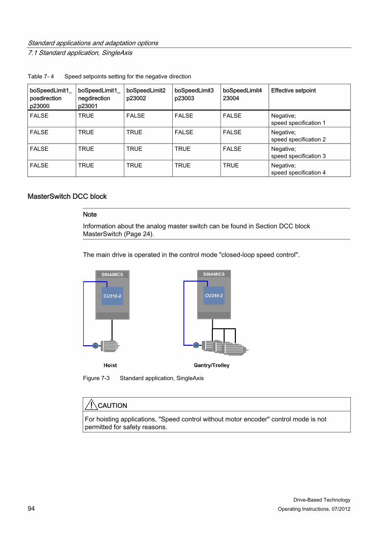
Standard applications and adaptation options 7.1 Standard application, SingleAxis
Drive-Based Technology 94 Operating Instructions, 07/2012
Table 7- 4 Speed setpoints setting for the negative direction
boSpeedLimit1_ posdirection p23000
boSpeedLimit1_ negdirection p23001
boSpeedLimit2 p23002
boSpeedLimit3 p23003
boSpeedLimit4 23004
Effective setpoint
FALSE TRUE FALSE FALSE FALSE Negative; speed specification 1
FALSE TRUE TRUE FALSE FALSE Negative; speed specification 2
FALSE TRUE TRUE TRUE FALSE Negative; speed specification 3
FALSE TRUE TRUE TRUE TRUE Negative; speed specification 4
MasterSwitch DCC block
Note
Information about the analog master switch can be found in Section DCC block MasterSwitch (Page 24).
The main drive is operated in the control mode "closed-loop speed control".
Figure 7-3 Standard application, SingleAxis
CAUTION For hoisting applications, "Speed control without motor encoder" control mode is not permitted for safety reasons.

Standard applications and adaptation options 7.1 Standard application, SingleAxis
Drive-Based Technology Operating Instructions, 07/2012 95
7.1.2 StartPulse in combination with brake control The StartPulse DCC block should be used in combination with the SINAMICS braking control.
After the command to open the brake, the appropriate torque must be applied for the load to prevent load sag. This is achieved using the start pulse. To do this, the torque at the output of the speed controller at standstill is retentively saved with p22071 "rTorqueValueRetain" before the brake is closed. The speed controller is set to the retentively saved value using parameter r22077 "rSetTorqueValue" when the signal to open the brake is output. This means that the torque is quickly established - therefore preventing load sag.
● The parameter p22072 "boCommandOpenBrake" should be interconnected with parameter r0899.12 / r1229.1.
● The parameter p22073 "boCommandCloseBrake" should be interconnected with parameter r0899.13.
Figure 7-4 CU310-2 hoist using the example of control via PROFIBUS
Figure 7-5 CU310-2 (gantry/trolley) using the example of the control via PROFIBUS
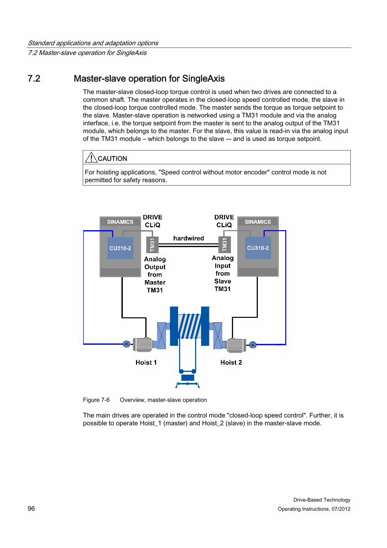
Standard applications and adaptation options 7.2 Master-slave operation for SingleAxis
Drive-Based Technology 96 Operating Instructions, 07/2012
7.2 Master-slave operation for SingleAxis The master-slave closed-loop torque control is used when two drives are connected to a common shaft. The master operates in the closed-loop speed controlled mode, the slave in the closed-loop torque controlled mode. The master sends the torque as torque setpoint to the slave. Master-slave operation is networked using a TM31 module and via the analog interface, i.e. the torque setpoint from the master is sent to the analog output of the TM31 module, which belongs to the master. For the slave, this value is read-in via the analog input of the TM31 module – which belongs to the slave –- and is used as torque setpoint.
CAUTION For hoisting applications, "Speed control without motor encoder" control mode is not permitted for safety reasons.
Figure 7-6 Overview, master-slave operation
The main drives are operated in the control mode "closed-loop speed control". Further, it is possible to operate Hoist_1 (master) and Hoist_2 (slave) in the master-slave mode.
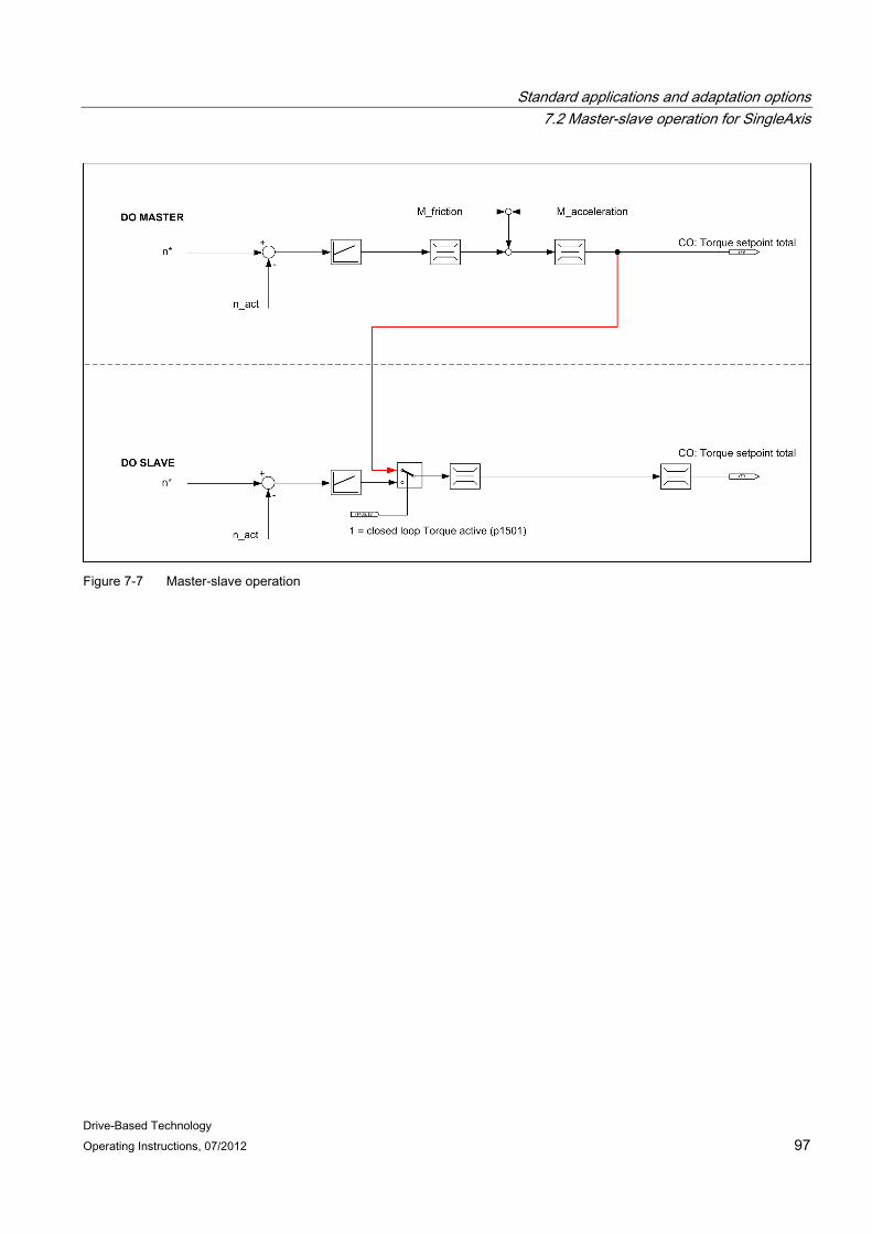
Standard applications and adaptation options 7.2 Master-slave operation for SingleAxis
Drive-Based Technology Operating Instructions, 07/2012 97
Figure 7-7 Master-slave operation

Standard applications and adaptation options 7.3 Expanding a standard application and DCC chart
Drive-Based Technology 98 Operating Instructions, 07/2012
7.3 Expanding a standard application and DCC chart In all standard applications, the know-how protected Crane DCC blocks are saved under the drive objects. As a consequence, this DCC chart cannot be opened under the drive objects – and application-specific DCC configurations cannot be made on the DCC chart. In general, a new DCC chart can be created under the SINAMICS CU control unit, see figure below. This chart can be configured in a user-specific way.
For standard applications, a DCC chart (User-DCC) already exists under the control unit. The customer-specific requirements can be implemented in this DCC chart.
Figure 7-8 Inserting a chart via PROFIBUS DP

Standard applications and adaptation options 7.4 Data units
Drive-Based Technology Operating Instructions, 07/2012 99
7.4 Data units The input and output variables of a DCC block can be declared in the form of an adjustable parameter as well as in the form of a BiCo parameter. Only connections of a DCC block declared as BiCo parameters can be connected to the connector inputs (CI) and connector outputs (CO) of the drive.
All block interfaces declared as BiCo parameters are per-unit variables. This means that calculations are performed with per-unit signal values within DCC. (1.0 corresponds to 100%). The conversion to the drive connectors - that have associated units - is performed automatically.
If an interconnection is established to the Crane DCC blocks from another DCC chart, then this value may only move in the range -2.0 to +2.0. This corresponds to a value range from -200 % up to +200 %.
If a connector output of DCC is interconnected with the basic device, this will always be interpreted as a referred value of the basic system. The absolute value in the basic device with the associated unit now depends on which unit and therefore which reference variable the selected connector input has in the basic system.
When interconnecting the connector input for speed setpoint p1070 (function plan 3030), the per-unit (referred) output value from the DCC chart will automatically be multiplied with the reference variable "Reference speed" p2000 (in the example p2000 = 1500 rpm). In the SINAMICS basic system, a speed setpoint of 1800 rpm ( = p2000 * 1.2 = 1500 rpm * 1.2) will thus become effective.
For BiCo interconnections to the basic system, it must therefore always be observed whether absolute variables or per-unit (referred) variables are being used in DCC. When interconnected with a connector input of the basic system with associated units, the connector output of the DCC chart will always (internally) be multiplied with its reference variable (with physical unit).
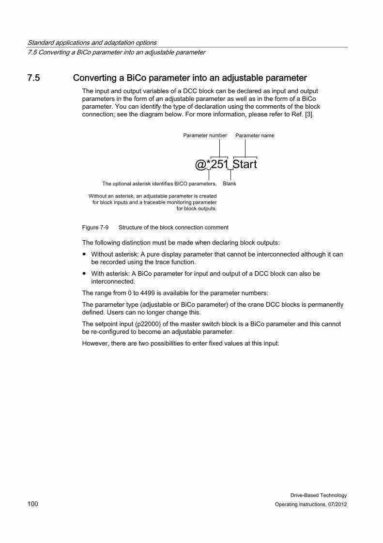
Standard applications and adaptation options 7.5 Converting a BiCo parameter into an adjustable parameter
Drive-Based Technology 100 Operating Instructions, 07/2012
7.5 Converting a BiCo parameter into an adjustable parameter The input and output variables of a DCC block can be declared as input and output parameters in the form of an adjustable parameter as well as in the form of a BiCo parameter. You can identify the type of declaration using the comments of the block connection; see the diagram below. For more information, please refer to Ref. [3].
Figure 7-9 Structure of the block connection comment
The following distinction must be made when declaring block outputs:
● Without asterisk: A pure display parameter that cannot be interconnected although it can be recorded using the trace function.
● With asterisk: A BiCo parameter for input and output of a DCC block can also be interconnected.
The range from 0 to 4499 is available for the parameter numbers:
The parameter type (adjustable or BiCo parameter) of the crane DCC blocks is permanently defined. Users can no longer change this.
The setpoint input (p22000) of the master switch block is a BiCo parameter and this cannot be re-configured to become an adjustable parameter.
However, there are two possibilities to enter fixed values at this input:
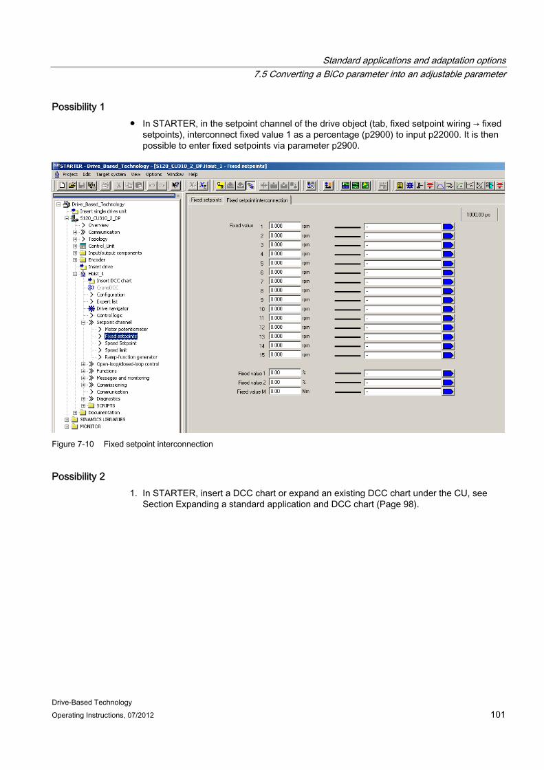
Standard applications and adaptation options 7.5 Converting a BiCo parameter into an adjustable parameter
Drive-Based Technology Operating Instructions, 07/2012 101
Possibility 1 ● In STARTER, in the setpoint channel of the drive object (tab, fixed setpoint wiring → fixed
setpoints), interconnect fixed value 1 as a percentage (p2900) to input p22000. It is then possible to enter fixed setpoints via parameter p2900.
Figure 7-10 Fixed setpoint interconnection
Possibility 2 1. In STARTER, insert a DCC chart or expand an existing DCC chart under the CU, see
Section Expanding a standard application and DCC chart (Page 98).
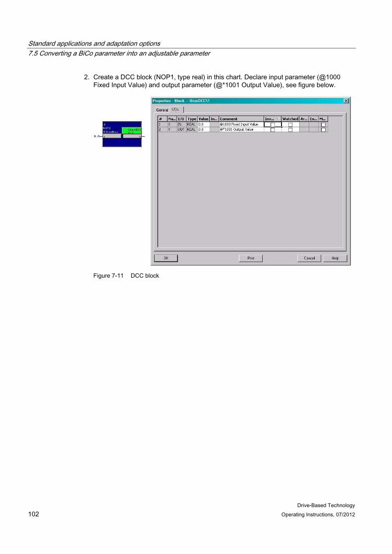
Standard applications and adaptation options 7.5 Converting a BiCo parameter into an adjustable parameter
Drive-Based Technology 102 Operating Instructions, 07/2012
2. Create a DCC block (NOP1, type real) in this chart. Declare input parameter (@1000 Fixed Input Value) and output parameter (@*1001 Output Value), see figure below.
Figure 7-11 DCC block
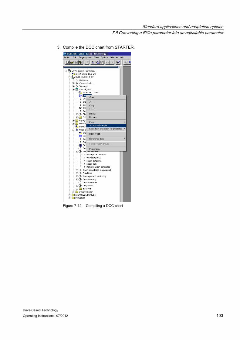
Standard applications and adaptation options 7.5 Converting a BiCo parameter into an adjustable parameter
Drive-Based Technology Operating Instructions, 07/2012 103
3. Compile the DCC chart from STARTER.
Figure 7-12 Compiling a DCC chart

Standard applications and adaptation options 7.5 Converting a BiCo parameter into an adjustable parameter
Drive-Based Technology 104 Operating Instructions, 07/2012
4. The two new parameters can now be seen under the expert list of the CU.
Figure 7-13 New parameters are visible

Standard applications and adaptation options 7.5 Converting a BiCo parameter into an adjustable parameter
Drive-Based Technology Operating Instructions, 07/2012 105
5. The setpoint input of the master switch in the crane DCC block can be interconnected with the output parameter.
Figure 7-14 Interconnecting the master switch setpoint
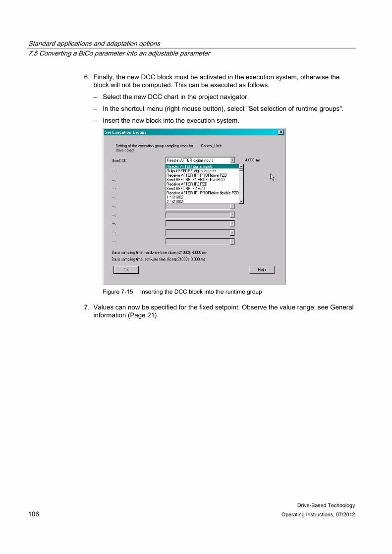
Standard applications and adaptation options 7.5 Converting a BiCo parameter into an adjustable parameter
Drive-Based Technology 106 Operating Instructions, 07/2012
6. Finally, the new DCC block must be activated in the execution system, otherwise the block will not be computed. This can be executed as follows.
– Select the new DCC chart in the project navigator.
– In the shortcut menu (right mouse button), select "Set selection of runtime groups".
– Insert the new block into the execution system.
Figure 7-15 Inserting the DCC block into the runtime group
7. Values can now be specified for the fixed setpoint. Observe the value range; see General information (Page 21).
Drive-Based Technology Operating Instructions, 07/2012 107
Spare parts / accessories 8
Spare parts ● Memory card for SINAMICS CU310 DP without increased performance (order number
6SL3054-0CG00-1AA0, SINAMICS V2.6.2)
● Memory card for SINAMICS CU310-2 DP (order number 6GA7270-1AA11-0AA0; can be supplied only in conjunction with SIMOCRANE Drive-Based Technology V1.0 SP1)
Supplementary components ● SINAMICS S120 CU310 DP (order number 6SL3040-0LA00-0AA1)
● SINAMICS STARTER V4.3 SP1 (DVD) (order number 6SL3072-0AA00-0AG0)
● DCC SINAMICS V2.2 SP1 (order number 6AU1810-1HA22-1XA0)
● SINAMICS Terminal Module TM31 (order number 6SL3055-0AA00-3AA1)
● SINAMICS S120 CU310-2 DP (order number 6SL3040-1LA00-0AA0)
Additional information is provided in the following catalogs to select and order supplementary components:
● Catalog CR1, 2012 – Drive and Control Components for Hoisting Gear
● Catalog PM21, 2011 – SIMOTION, SINAMICS S120 and Motors for Production Machines
● Distributed I/O, PROFIBUS: Catalog IK PI (Industrial Communication)
Note
Drive systems, motors and connection systems are not included in the package. These components must be ordered separately.

Spare parts / accessories
Drive-Based Technology 108 Operating Instructions, 07/2012

Drive-Based Technology Operating Instructions, 07/2012 109
Appendix AA.1 List of References
Ref. 1 SINAMICS S120 AC Drive Manual (GH6), 01/2012 Ref. 2 SINAMICS S120, S150 List Manual (LH1), 01/2012 Ref. 3 SINAMICS/SIMOTION Programming and Operating Manual Editor Description
DCC, 02/2012 Ref. 4 SINAMICS S120 Getting Started for the STARTER Commissioning Tool, 01/2012 Ref. 5 SINAMICS S120 Control Units and Additional System Components Manual (GH1),
01/2012 Ref. 6 SIMOCRANE, Basic Technology V3.0 Operating Instructions, 06/2012
A.2 Abbreviations Abbreviation German English BICO Binector Connector-Technologie Binector Connector Technology BOP Basic Operator Panel Basic Operator Panel CD Compact Disc Compact Disc CF Compact Flash Speicherkarte CompactFlash Card CU Control Unit Control Unit DCC Drive Control Chart Drive Control Chart DDS Antriebsdatensatz Drive Data Set DO Antriebsobjekt bei SINAMICS, z. B.
Motor Module Drive Object
FW Feldschwächung Field Weakening HTL Logik mit hoher Störschwelle High-Threshold Logic I/O Eingang / Ausgang Input/Output MS Meisterschalter Master Switch PLI Motorkurve (Polygonzug für Strom) Motor curve (current polygon) PLS Vorendschalter Pre-limit switch PZD PROFIBUS process data PROFIBUS process data SLS Safely limited speed Safely Limited Speed SSI Synchrone serielle Schnittstelle Synchronous Serial Interface STO Safe Torque Off Safe Torque Off TTL Transistor-Transistor-Logik Transistor-Transistor Logic
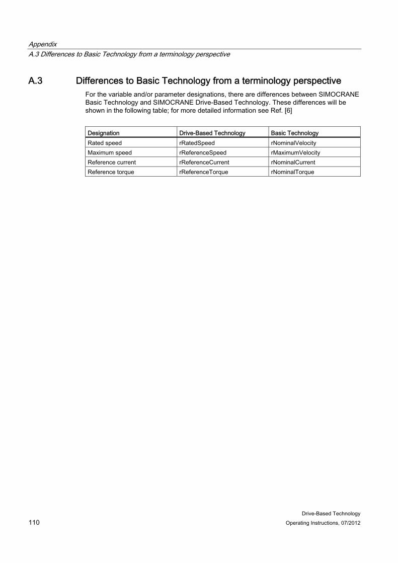
Appendix A.3 Differences to Basic Technology from a terminology perspective
Drive-Based Technology 110 Operating Instructions, 07/2012
A.3 Differences to Basic Technology from a terminology perspective For the variable and/or parameter designations, there are differences between SIMOCRANE Basic Technology and SIMOCRANE Drive-Based Technology. These differences will be shown in the following table; for more detailed information see Ref. [6]
Designation Drive-Based Technology Basic Technology Rated speed rRatedSpeed rNominalVelocity Maximum speed rReferenceSpeed rMaximumVelocity Reference current rReferenceCurrent rNominalCurrent Reference torque rReferenceTorque rNominalTorque