drum mower - tarrivermfg.comtarrivermfg.com/index_htm_files/drum mower - sept 2015.pdf · 3...
TRANSCRIPT
1
Publication #: January 2014
Drum Mower
Operator’s Manual
Parts Breakdown
Models:
BDR-135
BDR-165
BDR-185

2
TABLE OF CONTENTS
Introduction 3
Saftey Rules 4
Partial Risks 5
General Information 6
Operational Service 8
Connecting the Mower with the Tractor 8
Assembly of the PTO Shaft 9
Adjusting the Mower to Transport Position 10
Adjusting the Mower to Operational Position 12
Adjusting the Mower 14
Operating the Mower 16
Resting Position 17
Technical Maintenance of the Mower 18
Changing the Blades 18
V-Belt Tension 19
Everyday Maintenance 20
Post-Season Maintenance 20
Lubrication Instructions 20
Transport Lights 22
Assembly of Mower 23
Troubleshooting 24
Parts Breakdown 25
Warranty 45
3
INTRODUCTION
Thank you for purchasing your Tar River Drum Mower. This Operator’s Manual is available with every machine for
the purpose of introducing the user to the design, maintenance, and adjustment of the mower. It will also warn
against any possible threats. The Operator’s Manual includes information regarding the adjustment and transport on
the public roads.
Following the instructions carefully will ensure many years of damage-free and safe operation and will result in de-
creasing of the operational costs of the machine.
If you have any questions after reading this manual, please contact the Sales Representative or the Sales and Market-
ing Department.
To emphasize the importance of the information and the warnings of possible hazards, the following warning symbol
with a description has been used:
If you see this symbol, be aware of a threat, carefully read the appropriate information and inform other operators
about it.
The mower has a name plate placed on the middle frame with basic machine identification infor-
mation.
The warrantee proceedings rules and the rules resulting from them are written in the warrantee
card, which is an integral part of the Operator’s Manual.
The Operator’s Manual is part of the basic equipment of the machine and it should be kept for future use.
PRODUCT PURPOSE
The purpose of the Drum Mower is to be used in farming to mow the low stem green fodder (alfalfa grass, etc.) in the
fields and meadows.
Operating the mower in alternate conditions will be considered a misuse. Strict compliance with the requirements for
the use of the machine as well as its servicing and repairs by the manufacturer is a prerequisite for the intended use.
The machine should be used, operated and maintained only by persons who are familiarized with its specifics as well
as with the work safety proceedings rules.
The provisions regarding preventing accidents and all basic work safety and hygiene rules as well as the traffic regu-
lations must always be observed.
Any changes made to the machine without the consent of the manufacturer will exempt the manufacturer from the
responsibility for any possible damages resulting from them.

4
SAFETY RULES
PLEASE BE CAREFUL – READ THE OPERATOR’S MANUAL CAREFULY IN ORDER TO
PROTECT YOURSELF AND OTHERS FROM DANGER.
The machine should be used with respect to the basic work safety rules and the following precautions:
NEVER allow any unauthorized persons, unfamiliar with the Operator’s Manual or underage per-
sons, especially children, to use the machine.
ALWAYS check the physical condition of the machine, especially its wear and whether the operating elements
of the cutting system are properly secured.
YOU MUST replace the worn out or damaged parts with new ones.
THE MACHINE may be operated only with the recommended tractors equipped with the required front axle
load.
DURING the time of aggregating the machine with the tractor, special care should be exercised, and it is prohib-
ited for any persons to be present between the machine and the tractor while the engine is on.
IT IS UNACCEPTABLE to operate the machine without the shields and a guard, it is also prohibited to operate
the machine with damaged shields and lifted guard.
IT IS UNACCEPTABLE to operate the hydraulic lift lever externally.
PRIOR TO ANY OPERATION activities performed on the mower, it is necessary to disengage the power
take-off drive and the engine of the tractor, pull out the key from the ignition, and allow the operating drums and
the blades to come to a complete stop.
WHILE performing necessary operation activities required for the purpose of lifting the mower on the three-
point suspension system, it is very important to secure it additionally to prevent from detaching by a support or a
chain.
IT IS PROHIBITED to lift the mower with the power drive turned on and the cylinders rotating.
IT IS NECESSARY to check whether there are any persons or animals within the danger zone prior to turning
the driving power on or during operating the mower.
IT IS PROHIBITED to operate the machine with any bystanders present within less than 50m perimeter.
THE FIELDS AND MEADOWS TO BE MOWED should be free from any foreign and hard objects.
IT IS PROHIBITED to mow on the sides of the streets, public roads, public places (parks, schools, etc.) or plac-
es with stones in order to eliminate the risk of the hard objects thrown out.
THE MOWER SHOULD BE turned on only when in the operating position.
THE MOWING may be started only when the power take-off engine speed of 540 rev/min. is reached; it is pro-
hibited to surpass 600 rev/min.
IT IS PROHIBITED to operate the mower while driving backwards.
FOR TRANSPORT the mower should be in a transport position.
CHANGING the mower’s position from the transport position to the operating position should be performed on
a horizontal and even surface, with the blades lifted above the ground.
IT IS UNACCEPTABLE to carry on board any persons or any load while the machine is being transported or
while operating it.
WHILE on the public road, applicable provisions of the Traffic Regulations should be obeyed, and the mower
should be equipped with required lighting and warning devices in accordance to the local laws of a particular
country, where the machine is used.
NOT APPLYING the rules mentioned above may cause hazard for the operator of the machine and bystanders, as
well as it may cause damage to the machine. For the damages resulting from the failure to comply
with these rules, the responsibility will be on the side of the mower’s user.

5
PARTIAL RISKS
The manufacturer has made every effort to ensure that the design and the intended method of operating the mower
does not cause any danger to people and their environment.
Due to the nature of the mower and the lack of such opportunities to fully expose the cutter, certain elements of risk
can occur.
THE DANGER caused by the presence of the sharp edges of the cutting system and the possibili-
ties of any hard objects thrown out, e.g. stones, broken blades, etc. The danger zone resulting from
the possibility of throwing out hard objects is within 150 ft. perimeter from the mower being operat-
ed.
DANGER the working cylinders and the blades are still rotating for a certain amount of time even
after the power drive of the mower is turned off. Therefore, before proceeding with any work activ-
ities on the mower, it is crucial to wait until the operating drums with the blades stop rotating.
DANGER changing the mower’s position from the transport position to the operating position and
backwards may be performed only on an even and flat surface after prior leveling of the machine.
Failure to comply with these conditions may cause the cutting system of the mower turn around on
its own on the suspension and hit or deform the operating elements of the tractor.
SAFETY SIGNS AND INSCRIPTIONS
There are warning labels placed on the mower with safety signs in the form of pictograms, which give clear instruc-
tions and comments informing about what should be treated with special precaution in order for the operation of the
mower to be safe.
Carefully read every warning label and get familiarized with their meaning.
The warning labels should be kept clean and readable throughout the whole life of operating the mower. In case the
warning labels are not readable, the damaged labels should be replaced with new ones.
New systems and parts replaced during any repairs should have all required warning labels. The new labels may be
obtained from stores or from the manufacturer, as it is done with any other spare parts.

6
GENERAL INFORMATION
Sales Information
The technical condition and the equipment of the mower should be checked at the time of purchase.
It should be required from the equipment dealer to carefully fill out the Warranty Registration Form. Failure to pro-
vide the date of purchase or the dealer’s information might cause the buyer to suffer disapproval of any possible com-
plaints.
Equipment and Spare Parts
The mower includes the following basic equipment:
The Operator’s Manual, Parts Breakdown and Warranty Registration Form 1pc.
Blade Changing Tool 1pc.
Blades (packed) 18pcs
Design and Operation
The design of the mower:
1. Suspension
2. Central beam
3. Push rods, hydraulic cylinders (depending on the
version)
4. Main frame
5. Shield system
6. Stump jumper
7. Operating drums
8. Protective shield
9. Lock
7
The suspension system frame (1) is used to connect the mower with the tractor. The main frame (4) is connected piv-
otally with the suspension frame through the central beam (2). The cutting system is made of two operating drums
(7) with blades attached rotationally in their lower part. The drums rest on the stump jumpers (8) when in the operat-
ing position, which adjust to the ground contours.
Changing the position of the mower from the transport position to the operating position and backwards is made pos-
sible through the pivotal connection of the of the suspension system frame with the central beam. The guards and
shield (8) protect the machine operator and other people from any hard object, which might be thrown out from under
by the operating drums (7).
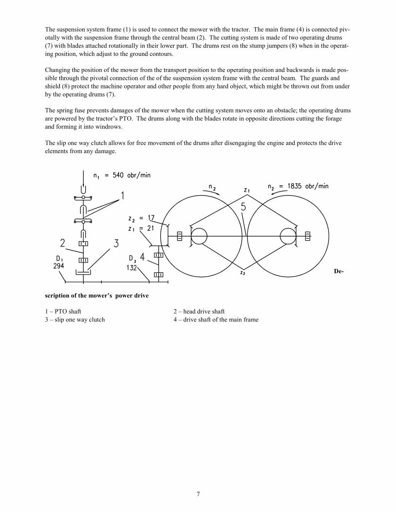
The spring fuse prevents damages of the mower when the cutting system moves onto an obstacle; the operating drums
are powered by the tractor’s PTO. The drums along with the blades rotate in opposite directions cutting the forage
and forming it into windrows.
The slip one way clutch allows for free movement of the drums after disengaging the engine and protects the drive
elements from any damage.
De-
scription of the mower’s power drive
1 – PTO shaft 2 – head drive shaft
3 – slip one way clutch 4 – drive shaft of the main frame
8
OPERATIONAL SERVICE
You may start operating the machine only after having carefully read the Operator’s Manual.
Prior to connecting the rotary mower to the recommended tractors, they should be properly prepared.
Check the physical condition of the machine and perform daily maintenance work in accordance to the operator’s
manual of the tractor.
Tilt or disassemble the elements of the connection and attachment system of the tractor, which may interfere or
cause collisions with the PTO shaft.
ATTENTION disassembling these elements will protect against any damage to the PTO shaft
while bringing down the suspension system to the lower end position
Assemble the tractor’s power take-off shaft shield
The recommended tractors should be equipped with the front axle weights
WARNING using a different than recommended tractor for the mower (e.g. of a lower pulling
power) or ones that are not equipped with the required front axle weights may cause loss of the
steering control of the tractor’s front wheels
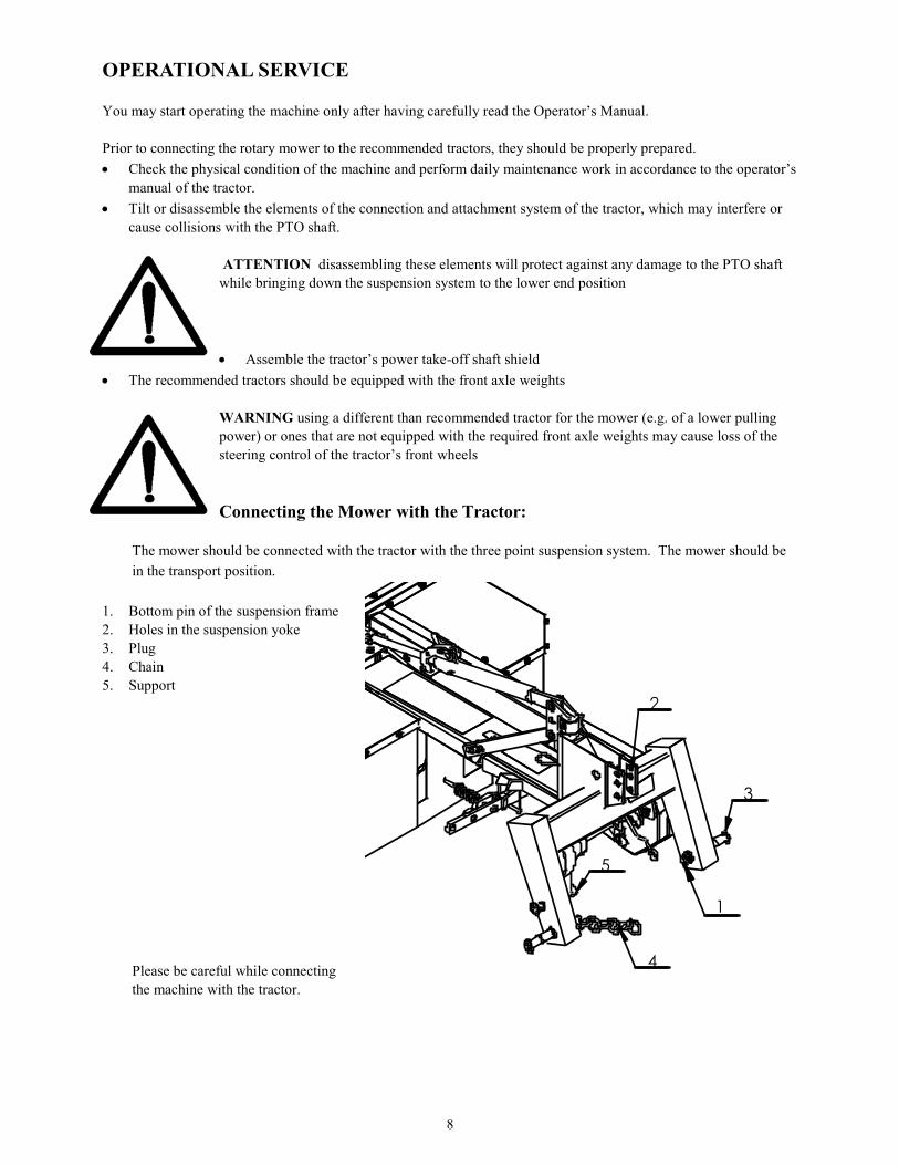
Connecting the Mower with the Tractor:
The mower should be connected with the tractor with the three point suspension system. The mower should be
in the transport position.
1. Bottom pin of the suspension frame
2. Holes in the suspension yoke
3. Plug
4. Chain
5. Support
Please be careful while connecting
the machine with the tractor.
1
2
5
3
4
9
IT IS UNACCEPTABLE
for any persons to be present between the machine and the tractor while backing up to the machine
to connect the machine while the tractor’s engine is on and the key is in the ignition
to use parts to secure connections other than recommended by the machine or tractor manufacturers.
In order to connect the mower to the tractor:
1. Insert the bottom push rods of the tractor (Drawing nr. 4, point 1) in the suspension frame pins (first the left one,
than the right one) and secure them with cotter pins (Drawing nr. 4, point 3).
2. Slide the end of the upper connector between the yoke plates using the holes, then connect it with a bolt and se-
cure it with a cotter pin.
3. Lift the mower to relieve the support (Drawing nr. 4, point 5
4. Lift the support and support it with a cotter pin.
5. Tighten the chain (Drawing nr. 4, point 4) that’s limiting the side tilting of the tractor’s suspension system.
Assembly of the PTO Shaft
The drum mower should be equipped with an efficient PTO shaft with a guard, safety sign or the CE marking as well
as the technical specifications in accordance with the technical guidelines.
Using a PTO shaft with parameters different than those recommended by the manufacturer of the machine may over-
load the shaft, damage it or result in pulling both parts apart while lifting the machine and so create hazard for the
operators and the environment.
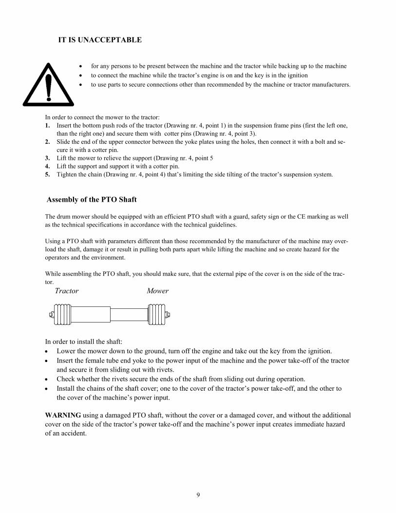
While assembling the PTO shaft, you should make sure, that the external pipe of the cover is on the side of the trac-
tor.
Tractor Mower
In order to install the shaft:
Lower the mower down to the ground, turn off the engine and take out the key from the ignition.
Insert the female tube end yoke to the power input of the machine and the power take-off of the tractor
and secure it from sliding out with rivets.
Check whether the rivets secure the ends of the shaft from sliding out during operation.
Install the chains of the shaft cover; one to the cover of the tractor’s power take-off, and the other to
the cover of the machine’s power input.
WARNING using a damaged PTO shaft, without the cover or a damaged cover, and without the additional
cover on the side of the tractor’s power take-off and the machine’s power input creates immediate hazard
of an accident.
Ci¹ gnik Kosiarka
10
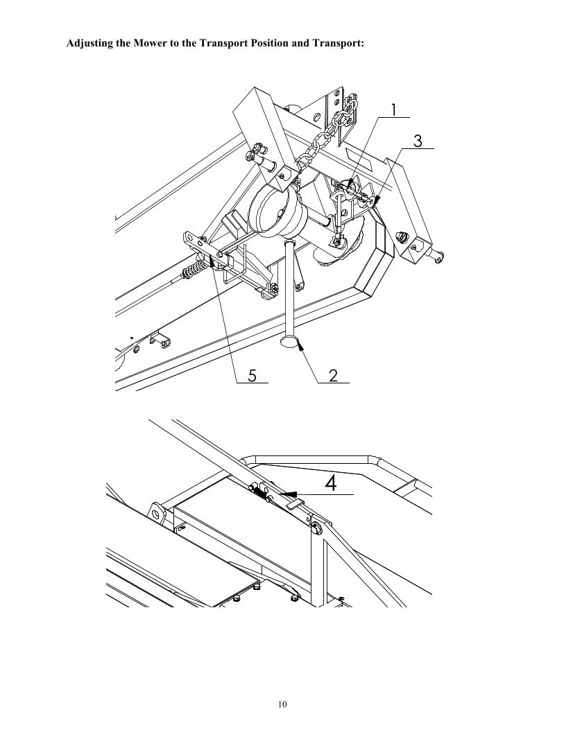
Adjusting the Mower to the Transport Position and Transport:
3
2
1
5
4

11
Be careful while changing the mower’s position from the transport position to the operating position and
the other way around.
It is prohibited to reposition the mower:
On an uneven surface and in a visible slope area.
When it is lifted high (as in the transport position), and when the suspension frame of the mower is not appropri-
ately level.
In the presence of bystanders within the mower’s turning range.
Failure to comply with these recommendations may result in risks associated with rapid and automatic rotation of
the mower on the suspension. Such rotation may occur after the securing elements pull free (point 1 rivets, point
4 gears)
In order to change the position of the mower to the transport position, the following must be done:
Set the unit (the mower and the tractor) on an even and horizontal surface.
Lower the mower so the stump jumpers rest on the ground.
Disengage the PTO, the tractor’s engine, and take out the key from the ignition and allow for the mower’s ele-
ments to come to a complete stop.
Disassemble the PTO shaft.
Level the mower with the right lift arm brace so the suspension frame pins are on the same level above the
ground.
Remove the fuse (Position 5 in the drawing on the previous page) from the bottom suspension frame pin.
In the mowers with the push rod system (Position 4 in the drawing on the previous page) move the gear to the
lower position.
Lift the mower with the tractor’s hydraulic lifting unit so the stump jumpers are just above the ground.
Lift the support (Position 2 in the drawing on the previous page) to the upper level and secure it with a cotter pin
Move the mower by hand all the way back along the tractor making sure that the king pin of the lock (Position 1
on the previous page) goes into the king pin opening (Position 3 on the previous page) with a loose line.
Lift the mower with the hydraulic system to the vertical position, and move the lever of the ball valve mounted
on the actuator into the locked position.
During the transport:
Lift the mower with the hydraulic lifting unit to the upper position to ensure the space between the stump jumper
of the cutting drum and the ground of at least 40cm, tighten the side chains of the tractor’s bottom push rods so the
machine doesn’t swing to the sides.
Always make sure that the ball valve is locked during transport.
Furthermore:
Check the securing elements
Install the warning plate with lights and the plate for slow-moving vehicles.
Pay attention to the mower overlap over the tractor during the turns or relapses.

12
Adjusting the Mower to the Operational Position
Reposition the mower from the transport position to the operating position prior to starting the operation. In order to
do that, the following must be done:
Place the unit (the mower and the tractor) on an even, horizontal surface.
Move the ball valve lever to the open position in the mowers with the hydraulic cylinder ( it stays in that position
throughout the entire time of the mowers operation), and then move the mower to the horizontal position. Be
extra careful when lowering the mower from the vertical position to the horizontal position. Pay attention to the
space available for the operation.
In the mower with the push rods system, the gear should be moved to the upper position (Position 4 in the draw-
ing below), and then lower the mower to just above the ground.
Stand behind the machine (shown in the top drawing on the following page in the X spot) and pull the line caus-
ing the latch to slide out (Position 1 in the bottom drawing on the following page) from the opening (Position 3),
take the mower by the cutting system’s cover and turn it to the operating position.
Put the fuse in (Position 1) the upper suspension frame pin (Position 2) and secure it with a cotter (Position 3).
Proper positioning of the mower in the operating position ensures a safe and high quality and efficiency operation.
The PTO shaft may be connected to the tractor only during the time of the mower’s operation, but
during transport or maintenance works it should be disassembled.
Gear’s operating position
4

13
Changing the mower’s position from the transport position to the operating position and the other way back.
Changing the mower’s position to the operating position
1
3
2
14
Adjusting the Mower
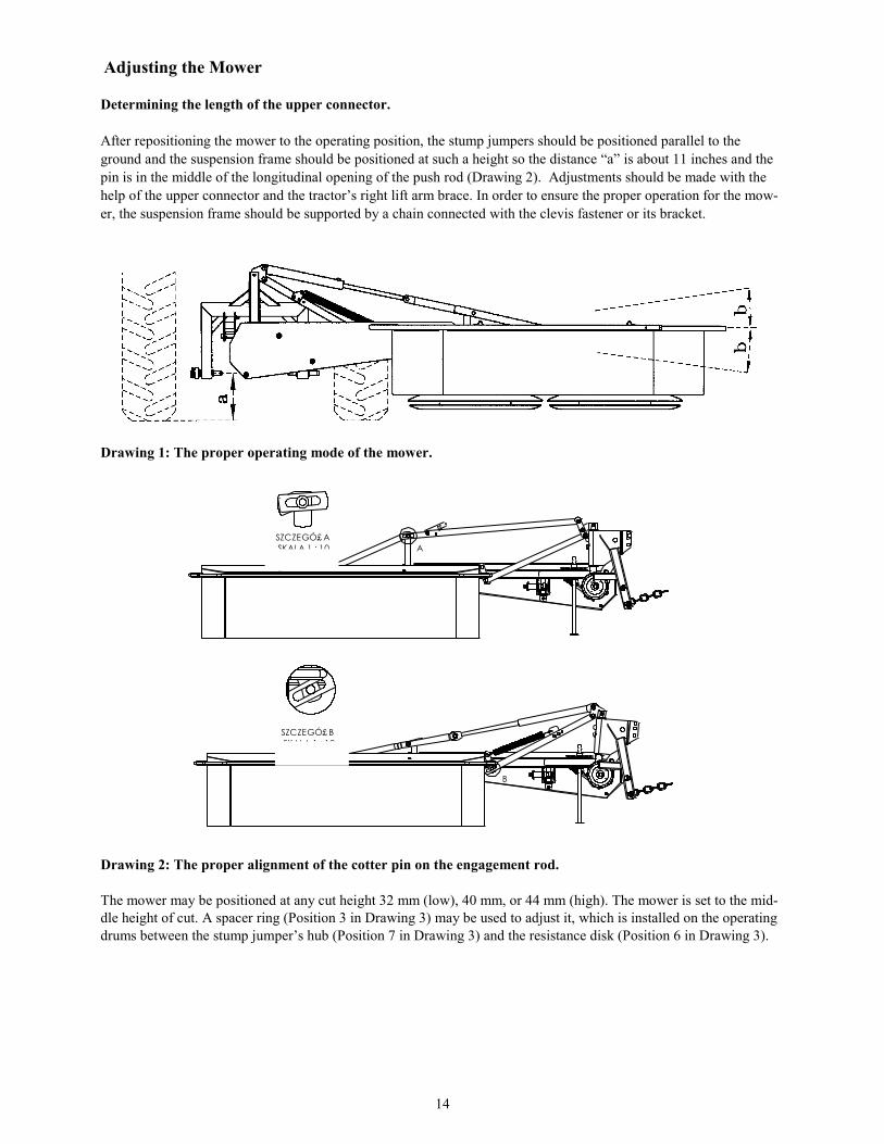
Determining the length of the upper connector.
After repositioning the mower to the operating position, the stump jumpers should be positioned parallel to the
ground and the suspension frame should be positioned at such a height so the distance “a” is about 11 inches and the
pin is in the middle of the longitudinal opening of the push rod (Drawing 2). Adjustments should be made with the
help of the upper connector and the tractor’s right lift arm brace. In order to ensure the proper operation for the mow-
er, the suspension frame should be supported by a chain connected with the clevis fastener or its bracket.
Drawing 1: The proper operating mode of the mower.
Drawing 2: The proper alignment of the cotter pin on the engagement rod.
The mower may be positioned at any cut height 32 mm (low), 40 mm, or 44 mm (high). The mower is set to the mid-
dle height of cut. A spacer ring (Position 3 in Drawing 3) may be used to adjust it, which is installed on the operating
drums between the stump jumper’s hub (Position 7 in Drawing 3) and the resistance disk (Position 6 in Drawing 3).
A
SZCZEGÓ£ A
SKALA 1 : 10
B
SZCZEGÓ£ B
SKALA 1 : 10
15
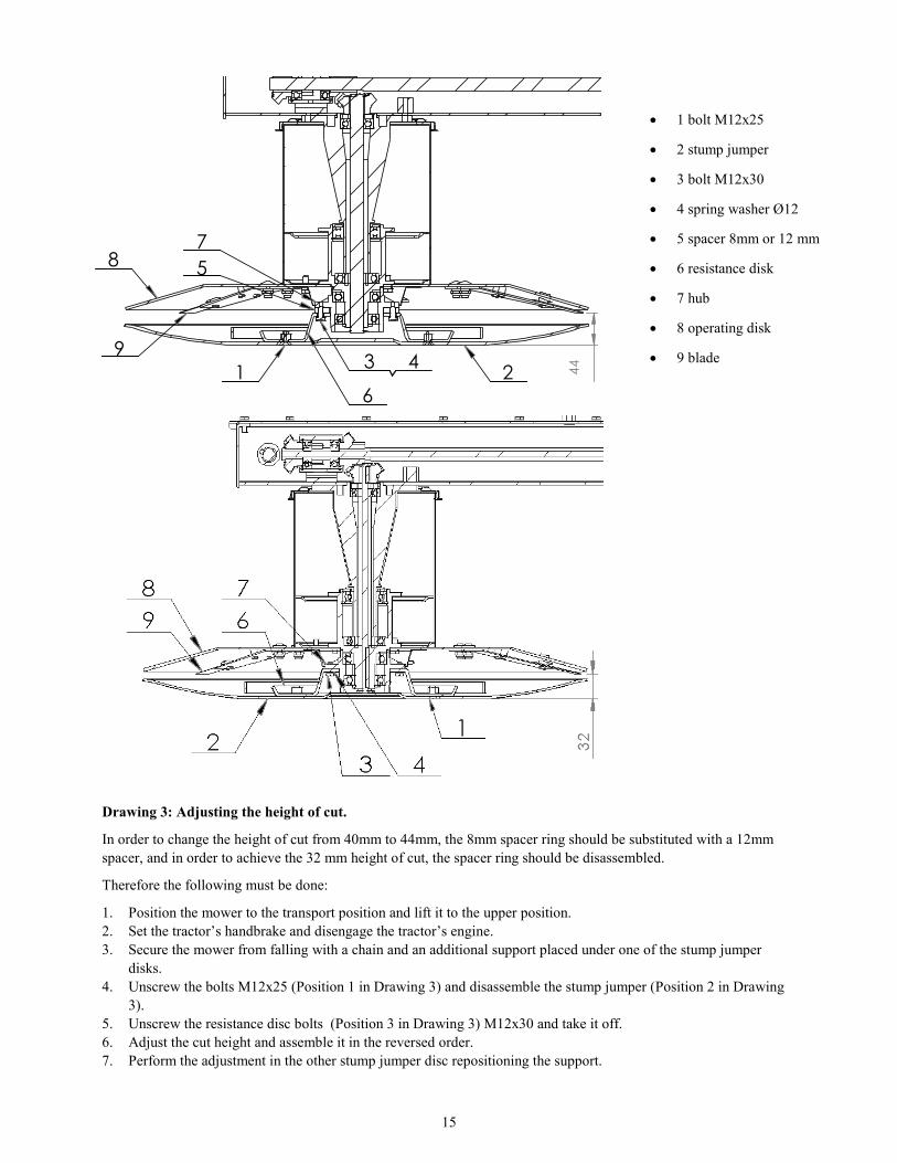
Drawing 3: Adjusting the height of cut.
In order to change the height of cut from 40mm to 44mm, the 8mm spacer ring should be substituted with a 12mm
spacer, and in order to achieve the 32 mm height of cut, the spacer ring should be disassembled.
Therefore the following must be done:
1. Position the mower to the transport position and lift it to the upper position.
2. Set the tractor’s handbrake and disengage the tractor’s engine.
3. Secure the mower from falling with a chain and an additional support placed under one of the stump jumper
disks.
4. Unscrew the bolts M12x25 (Position 1 in Drawing 3) and disassemble the stump jumper (Position 2 in Drawing
3).
5. Unscrew the resistance disc bolts (Position 3 in Drawing 3) M12x30 and take it off.
6. Adjust the cut height and assemble it in the reversed order.
7. Perform the adjustment in the other stump jumper disc repositioning the support.
1 bolt M12x25
2 stump jumper
3 bolt M12x30
4 spring washer Ø12
5 spacer 8mm or 12 mm
6 resistance disk
7 hub
8 operating disk
9 blade
C C
1 2
5
4
6
8
93
7
44

16
Operating the Mower
The fields and meadows to be mowed should be free from any foreign and/or hard object or stones, which may dam-
age the mower.
The shields of the mower must be positioned downwards during operating of the machine. The mower’s drive should
be turned on slowly and after reaching 540 RPM of the power take-off, the operation may be started. The speed
should be adjusted to the terrain conditions and the type of grass to be mowed. For the time of idle drive, the drive of
the mower should be turned off and then the mower should be lifted upwards.
The mower shouldn’t be used on uneven and full of stones fields because of the risk of damaging the
blades, holders, and other mower’s elements, as well as because of the risk of the hard objects thrown
out (stones, broken blades, etc.).
WARNING The operating drums and the blades still rotate for a certain amount of time even after the
power take-off drive is turned off. Prior to making any adjustments on the mower, turn off the drive
and the engine of the tractor, pull out the key from the ignition, and allow for the operating drums and
the blades to come to a complete stop.
WARNING: It is prohibited to:
Operate the mower in the presence of bystanders within a less than 165 ft. perimeter.
In case the mower hits an obstacle, the fuse allows for the cutting system to tilt. The tractor then should
be stopped and the drive should be turned off. The fuse gets back in when the tractor is moved back a
bit. The length of the A fuse’s tighten spring should be 65mm. If it is too tight, it may block the fuse and damage the
mower when it hits an obstacle.
Securing the mower after driving into an obstacle.
ATTENTION: because of the possibility to damage the mower, never:
exceed the tractor’s PTO 600 RPM
lift the mower while the drive is engaged and the drums are rotating
mow while backing up (this will cause machine failure!)

17
Resting Position
The mower in the resting position is completely separated from the tractor’s suspension system. The mower is repo-
sitioned from the transport position to the resting position.
The following should be done for that purpose:
With the three point suspension system, the support of the mower should be lowered and secured with a cotter.
Lower the mower and rest it on the stump jumper discs and the support.
Disengage the engine and pull out the key from the ignition and set the brakes.
Disconnect the pivotal end of the tractor’s upper connector from the suspension frame yoke.
Take down the tractor’s push rod ball joint from the suspension frame pins.
18
TECHNICAL MAINTENANCE OF THE MOWER
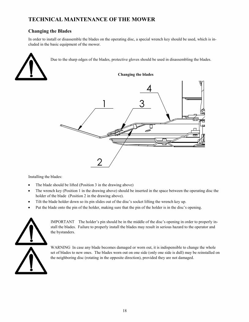
Changing the Blades
In order to install or disassemble the blades on the operating disc, a special wrench key should be used, which is in-
cluded in the basic equipment of the mower.
Due to the sharp edges of the blades, protective gloves should be used in disassembling the blades.
Changing the blades
Installing the blades:
The blade should be lifted (Position 3 in the drawing above)
The wrench key (Position 1 in the drawing above) should be inserted in the space between the operating disc the
holder of the blade (Position 2 in the drawing above).
Tilt the blade holder down so its pin slides out of the disc’s socket lifting the wrench key up.
Put the blade onto the pin of the holder, making sure that the pin of the holder is in the disc’s opening.
IMPORTANT The holder’s pin should be in the middle of the disc’s opening in order to properly in-
stall the blades. Failure to properly install the blades may result in serious hazard to the operator and
the bystanders.
WARNING In case any blade becomes damaged or worn out, it is indispensible to change the whole
set of blades to new ones. The blades worn out on one side (only one side is dull) may be reinstalled on
the neighboring disc (rotating in the opposite direction), provided they are not damaged.
BB
1
2
3
4
19
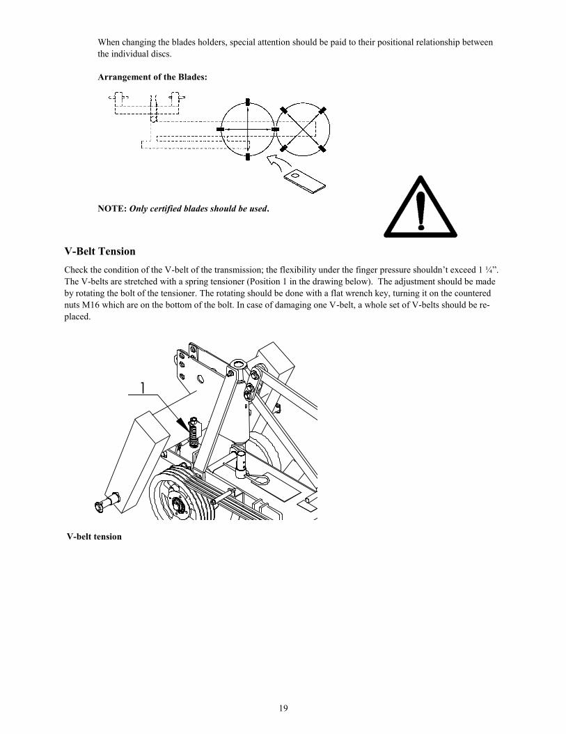
When changing the blades holders, special attention should be paid to their positional relationship between
the individual discs.
Arrangement of the Blades:
NOTE: Only certified blades should be used.
V-Belt Tension
Check the condition of the V-belt of the transmission; the flexibility under the finger pressure shouldn’t exceed 1 ¼”.
The V-belts are stretched with a spring tensioner (Position 1 in the drawing below). The adjustment should be made
by rotating the bolt of the tensioner. The rotating should be done with a flat wrench key, turning it on the countered
nuts M16 which are on the bottom of the bolt. In case of damaging one V-belt, a whole set of V-belts should be re-
placed.
V-belt tension
1

20
Everyday Maintenance
Following operation, clean the mower from any plant residues or dirt and check its technical condition every day.
Inspect the components and their connections.
All loosened bolt connections should be tightened, and the worn out or damaged parts should be replaced with
new original spare parts.
Pay attention to the cutting system; the worn or damaged blades, holders should be replaced as whole sets to new
ones.
Check the tension of the V-belts
Lubricate the mower and the PTO shaft in accordance with the lubricating instructions.
Post-Season Maintenance
When the operating season is over, the following must be done:
Thoroughly wash the mower.
Perform a detailed technical inspection of particular parts and components.
The worn out or damaged parts should be replaced with new ones.
Loosen up the V-belts.
Perform post seasonal servicing on the mower
Places with a damaged paint layer should be repainted.
Secure the operational surfaces with worn paint layer with a corrosion protection product.
Change the transmission oil (main frame), lubricate the machine in accordance with the lubricating instructions.
Lubrication Instructions
Perform the following maintenance activities:
Gear Box:
Check the oil levels every 10 hours with the help of a clean rod inserted in the vent opening. The level of the oil
should be 20-30mm from the bottom of the gear box. In case the oil level is low, the cause of the leakage should
be removed first, and then the oil should be refilled to the required level. There should be 5 liters of oil in the
gear box.
The instructions for lubricating the mower.

21
The greasing points indicated by triangles should be greased with a machine oil with the help of a lubricator.
The PTO shaft should be lubricated in accordance with the shaft manufacturer’s requirements.
REMEMBER: The higher quality and viscosity 90 Wt. gear oil should be used or alternately 140 Wt.
gear oil.
Storing The mower should be stored in a dry, hardened surface and roofed place that is of limited accessibility to people and
animals.
In case the mower is exposed to adverse weather conditions, it is necessary to perform maintenance and lubricating
on the machine.
Check the stability of the mower after placing it in the storage place. Positioning the mower on a soft and uneven
surface may be hazardous.

22
Transport Lights
The mower should always be positioned horizontally or vertically in the driving direction (behind the tractor).
During a transport, the machine must be equipped with the warning triangle sign (1) and a portable
warning light device (2) consisting of two rectangular plates painted with white and red stripes, to which composite
tubes are assembled with side position lights, stop lights and turn signals. During a transport of the mower in the ver-
tical position, the shields cannot cover the warning lights. If so, the shields should be pressed closer to the upper met-
al covers and tied up with a twine in several places.
1
2
23
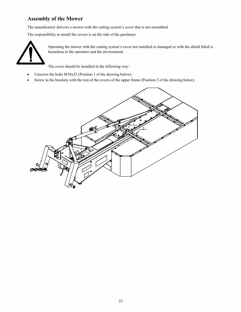
Assembly of the Mower
The manufacturer delivers a mower with the cutting system’s cover that is not assembled.
The responsibility to install the covers is on the side of the purchaser.
Operating the mower with the cutting system’s cover not installed or damaged or with the shield lifted is
hazardous to the operators and the environment.
The cover should be installed in the following way:
Unscrew the bolts M10x25 (Position 1 of the drawing below).
Screw in the brackets with the rest of the covers of the upper frame (Position 2 of the drawing below).
12
24
Dismantling, Utilization, and the Methods of Utilization.
Protect your hands (body) from injuries and harmful effects of lubricants and oils. Use protective
gloves and tools in good technical condition. The elements of the machine which may reposition or turn
during the disassembling should be appropriately secured.
The worn out or damaged parts obtained during repairs (dismantling) should be stored in a segregated place of limited
accessibility to people and animals. The worn out elements should be delivered to the scrap collection center. The
worn out elements made of plastic material should be delivered to the storage (disposal) of waste chemicals.
Do not spill oil during the time of refilling or changing it. The used oil should be stored in tight containers and peri-
odically deliver it to the oil utilization centers.
The abandoned parts or elements of the machine or spilled oil may result in accidents and cause envi-
ronmental pollution and violate the rules.
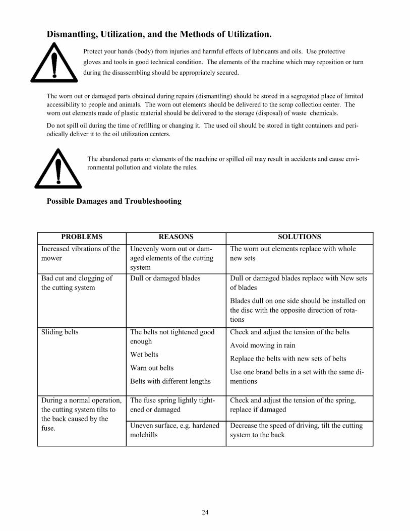
Possible Damages and Troubleshooting
PROBLEMS REASONS SOLUTIONS
Increased vibrations of the
mower
Unevenly worn out or dam-
aged elements of the cutting
system
The worn out elements replace with whole
new sets
Bad cut and clogging of
the cutting system
Dull or damaged blades Dull or damaged blades replace with New sets
of blades
Blades dull on one side should be installed on
the disc with the opposite direction of rota-
tions
Sliding belts
The belts not tightened good
enough
Wet belts
Warn out belts
Belts with different lengths
Check and adjust the tension of the belts
Avoid mowing in rain
Replace the belts with new sets of belts
Use one brand belts in a set with the same di-
mentions
During a normal operation,
the cutting system tilts to
the back caused by the
fuse.
The fuse spring lightly tight-
ened or damaged
Check and adjust the tension of the spring,
replace if damaged
Uneven surface, e.g. hardened
molehills
Decrease the speed of driving, tilt the cutting
system to the back

25
PARTS
BREAKDOWN
Models:
BDR-135
BDR-165
BDR-185
26
Belco Resources Equipment BDR-135 ~ BDR-165 ~ BDR-185
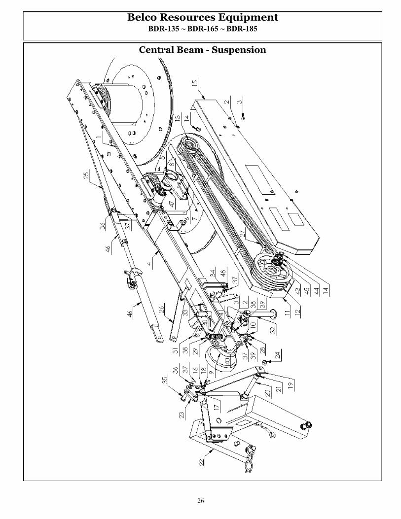
Central Beam - Suspension

27
Belco Resources Equipment BDR-135 ~ BDR-165 ~ BDR-185
Position Part # Description Qty 1 DM90135 Main Frame BDR-135 1
DM90165 Main Frame BDR-165 1
DM90185 Main Frame BDR-185 1
2 DM82005 Washer 5
3 NM10000 Nut M10 9
4 DM20175-35 Central Beam BDR-135 1
DM20175-65 Central Beam BDR-165 1
DM20175-85 Central Beam BDR-185 1
5 DM10180-35 Yoke BDR-135 1
DM10180-65 Yoke BDR-165 1
DM10180-85 Yoke BDR-185 1
6 DMT0206 Push Rod 1
7 DM10088 Star Washer 1
8 DM82105 Bolt 2
9 DM21903 Head (PTO Cover) 1
10 DM83002 Pin 16h9x40/34-5H 1
11 DMT0211 Belt Cover BDR-135 1
DM20144 Belt Cover BDR-165 1
DM20162 Belt Cover BDR-185 1
12 DM20452 Pulley 1
13 DM10250 Pulley 1
14 DMT0214 Retaining ring 2
15 DMT0215 External belts cover BDR-135 1
DM20157 External belts cover BDR-165 1
DM20251 External belts cover BDR-185 1
16 FW12000 Washer Ø12 2
17 BM12100 Bolt M12x100 1
18 DM82144 Self locking counter nut M12 1
19 DM20391-35 Clevis BDR-135 1
DM20391-65 Clevis BDR-165 1
DM20391-85 Clevis BDR-185 1
20 DM20131 Angular axis 1
21 DM20389 Pivot bushing 2
22 DMT0422 A Frame BDR-135 1
DM20646 A Frame BDR-165 1
DM20892 A Frame BDR-185 1
23 DM20083 Hitch head 1
24 NM20000 Nut M20 1
25 DM10110-35 Frame rod BDR-135 1
DM10110-65 Frame rod BDR-165 1
DM10110-85 Frame rod BDR-185 1

28
Belco Resources Equipment BDR-135 ~ BDR-165 ~ BDR-185
Central Beam - Suspension
29
Belco Resources Equipment BDR-135 ~ BDR-165 ~ BDR-185
Position Part # Description Qty
26 DM20096-35 Rear clevis BDR-135 1
DM20096-65 Rear clevis BDR-165 1
DM20096-85 Rear clevis BDR-185 1
27 SPA2832 V-Belt BDR-135 3
SPA2932 V-Belt BDR-165 4
SPA3185 V-Belt BDR-185 4
28 DM020246 Bolt tensioner 1
29 DM020307 Spring cap 1
30 DM20409 Angle bracket 1
31 DM20290 Lock 1
32 DM20760 Support 1
33 DM11024 Spring pin 1
34 DMT0234 Lock pin 1
35 DM83002 King pin 3
36 DM82005 Washer Ø25 4
37 DM82001 Cotter pin 6
38 NM16000 Nut M16 2
39 FW16000 Washer Ø16 2
40 DM20100 Lock faceplate 1
41 DM20218 Spring 1
42 BM10300 Bolt M10x30 1
43 B600900 Bearing 6009 1
44 SRE4500 Securing ring Z45 1
45 DMT0245 Securing ring Z75 1
46 DMT0246 Cylinder 1
47 DMT0247 Sleeve bearing BDR-135 2
DM10291 Sleeve bearing BDR-165 2
DM10177 Sleeve bearing BDR-185 2
48 FW20000 Washer Ø20 1
30
Belco Resources Equipment BDR-135 ~ BDR-165 ~ BDR-185
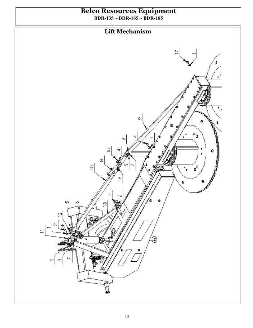
Lift Mechanism
31
Belco Resources Equipment BDR-135 ~ BDR-165 ~ BDR-185
Position Part # Description Qty
1 LW12000 Washer Ø12 4
2 BM1217590 Bolt M12x90 1
3 NM12000 Nut M12 1
4 BM1217530 Bolt M12x30 3
5 DM83002 King pin 025 4
6 DM82005 Washer Ø25 5
7 DM82001 Cotter pin 7
8 DM20220 Locking bar 1
9 DMT0309 Main frame push rod BDR-135 1
DM10235 Main frame push rod BDR-165 1
DM10110 Main frame push rod BDR-185 1
10 DM20070-35 Front push rod BDR-135 1
DM20070-65 Front push rod BDR-165 1
DM20070-85 Front push rod BDR-185 1
11 DM20083 Head 1
12 DM20103 Front push rod connector 2
13 DM20096-35 Short push rod BDR-135 1
DM20096-65 Short push rod BDR-165 1
DM20096-85 Short push rod BDR-185 1
14 DM82005 Washer Ø16 3
15 SR Securing ring Z13 1
16 DM20526 Push rod spring 1
17 BM1217530 Bolt M12x30 1

32
Belco Resources Equipment BDR-135 ~ BDR-165 ~ BDR-185
A Frame

33
Belco Resources Equipment BDR-135 ~ BDR-165 ~ BDR-185
Position Part # Description Qty
1 DMT0422 A Frame - BDR-135 1
DM20646 A Frame - BDR-165 1
DM20892 A Frame - BDR-185 1
2 DMT0402 Hitch Pin—BDR-135 & BDR-165 2
DMT0408 Hitch Pin—BDR-185 2
3 DMT0403 Latch 1
4 DMT0404 Spring 1
5 DM82001 Cotter pin 1
6 DMT0406 Lynch Pin 3
7 DM20274 Chain 1
9 FW24000 Washer Ø24 2
10 LN24000 Self locking counter nut M24 2
34
Belco Resources Equipment BDR-135 ~ BDR-165 ~ BDR-185
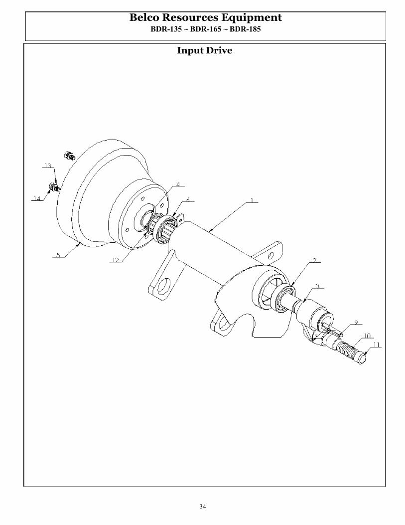
Input Drive

35
Belco Resources Equipment BDR-135 ~ BDR-165 ~ BDR-185
Position Part # Description Qty
1 DM20513 Drive head 1
2 B6206 Bearing 6206 1
3 DM20602 Drive shaft 1
4 SRE35000 Retaining ring Z35 1
5 DM21903 PTO Shield 1
6 B6007 Bearing 6007 1
7 KM080756 Pin 8x7x56 1
8 DM20172 Carrier 1
9 DM20205 Bushing 1
10 DM20218 Spring 1
11 DM20198 Carrier king pin 1
12 DM20615 Securing ring 1
13 FW8000 Washer Ø8 4
14 BM812520 Bolt M8x20 4
DM90513 Drive Head Complete (Pos. 1-2-3-6)

36
Belco Resources Equipment BDR-135 ~ BDR-165 ~ BDR-185
Breakaway Bar

37
Belco Resources Equipment BDR-135 ~ BDR-165 ~ BDR-185
Position Part # Description Qty
1 DM20290 Lower sliding bar 1
2 DM20291 Upper sliding bar 1
3 DM20322 Lock fuse 1
4 BM1420260 Bolt M14x260 1
5 DM20310 Lock spacer sleeve 1
6 FW14000 Washer Ø14 1
7 NM14000 Nut M14 2
8 DM20348 Spring 1
9 DM20307 Spring cap 1
DM90290 Breakaway Assembly Complete

38
Belco Resources Equipment BDR-135 ~ BDR-165 ~ BDR-185
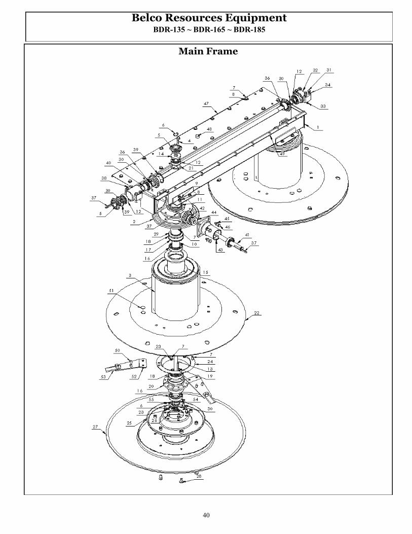
Main Frame

39
Belco Resources Equipment BDR-135 ~ BDR-165 ~ BDR-185
Position Part # Description Qty
1 DM10192-135 Frame-135 1
DM10192-165 Frame-165 1
DM10192-185 Frame-185 1
2 DM10365 Drum plug 2
3 DM10721 Operating drum 2
4 DM10156 Inlet 8x7x32 2
5 DM10019 Bevel gear 3
6 DM85111 Retaining ring Z25 4
7 BM101525 Bolt M10x25 44
8 FW10000 Washer Ø10 28
9 NM10000 Nut M10 8
10 DM10747 Drum hub 2
11 DM10543 O-ring Ø75 2
12 B6305 Bearing 6305 6
13 DM10617 Reducing gear drive shaft 2
14 DM86965 Sealant 2
15 DM10790 Operating disc hub 2
16 B6209 Bearing 6209 4
17 DMT0717 Retaining ring 2
18 B6210 Bearing 6210 4
19 DM10584 Inlet 8x7x80 2
20 DM10775 Stump jumper disc hub 2
21 DM10057 Spacer washer 2
22 DM20021-135 Operating disc - 135 2
DM20021-165 Operating disc - 165 2
DM20021-185 Operating disc - 185 2
23 LW10000 Spring washer Ø10 46
24 DM10439 Cover 2
25 DM10340 Resistive disc 2
26 BM101525 Bolt M10x25 12
27 DM10528-135 Stump jumper disc - 135 2
DM10528-165 Stump jumper disc - 165 2
DM10528-185 Stump jumper disc - 185 2
28 BM1212525 Bolt M12x25 12
29 DM10031 Sealant 2
40
Belco Resources Equipment BDR-135 ~ BDR-165 ~ BDR-185
Main Frame
41
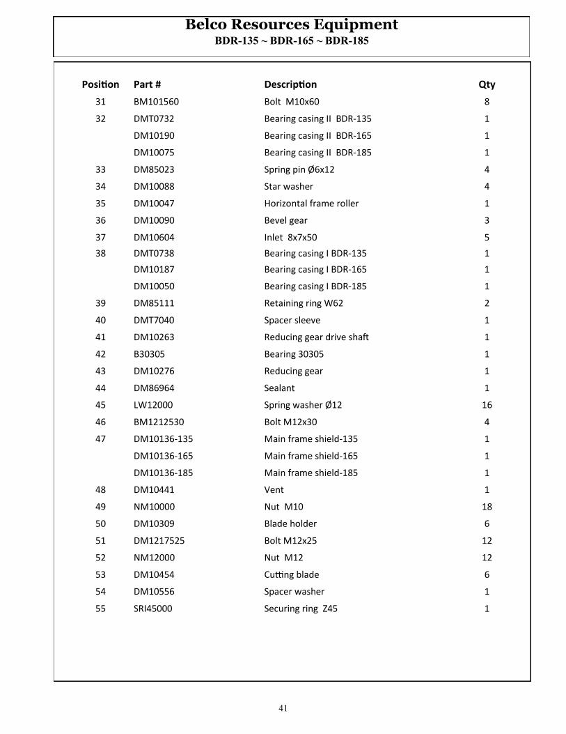
Belco Resources Equipment BDR-135 ~ BDR-165 ~ BDR-185
Position Part # Description Qty
31 BM101560 Bolt M10x60 8
32 DMT0732 Bearing casing II BDR-135 1
DM10190 Bearing casing II BDR-165 1
DM10075 Bearing casing II BDR-185 1
33 DM85023 Spring pin Ø6x12 4
34 DM10088 Star washer 4
35 DM10047 Horizontal frame roller 1
36 DM10090 Bevel gear 3
37 DM10604 Inlet 8x7x50 5
38 DMT0738 Bearing casing I BDR-135 1
DM10187 Bearing casing I BDR-165 1
DM10050 Bearing casing I BDR-185 1
39 DM85111 Retaining ring W62 2
40 DMT7040 Spacer sleeve 1
41 DM10263 Reducing gear drive shaft 1
42 B30305 Bearing 30305 1
43 DM10276 Reducing gear 1
44 DM86964 Sealant 1
45 LW12000 Spring washer Ø12 16
46 BM1212530 Bolt M12x30 4
47 DM10136-135 Main frame shield-135 1
DM10136-165 Main frame shield-165 1
DM10136-185 Main frame shield-185 1
48 DM10441 Vent 1
49 NM10000 Nut M10 18
50 DM10309 Blade holder 6
51 DM1217525 Bolt M12x25 12
52 NM12000 Nut M12 12
53 DM10454 Cutting blade 6
54 DM10556 Spacer washer 1
55 SRI45000 Securing ring Z45 1

42
Belco Resources Equipment BDR-135 ~ BDR-165 ~ BDR-185
Covers
15
43
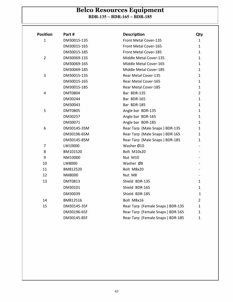
Belco Resources Equipment BDR-135 ~ BDR-165 ~ BDR-185
Position Part # Description Qty
1 DM30015-135 Front Metal Cover-135 1
DM30015-165 Front Metal Cover-165 1
DM30015-185 Front Metal Cover-185 1
2 DM30069-135 Middle Metal Cover-135 1
DM30069-165 Middle Metal Cover-165 1
DM30069-185 Middle Metal Cover-185 1
3 DM30015-135 Rear Metal Cover-135 1
DM30015-165 Rear Metal Cover-165 1
DM30015-185 Rear Metal Cover-185 1
4 DMT0804 Bar BDR-135 2
DM30244 Bar BDR-165 1
DM30043 Bar BDR-185 1
5 DMT0805 Angle bar BDR-135 1
DM30257 Angle bar BDR-165 1
DM30071 Angle bar BDR-185 1
6 DM30145-35M Rear Tarp (Male Snaps ) BDR-135 1
DM30196-65M Rear Tarp (Male Snaps ) BDR-165 1
DM30145-85M Rear Tarp (Male Snaps ) BDR-185 1
7 LW10000 Washer Ø10 -
8 BM101520 Bolt M10x20 -
9 NM10000 Nut M10 -
10 LW8000 Washer Ø8 -
11 BM812520 Bolt M8x20 -
12 NM8000 Nut M8 -
13 DMT0813 Shield BDR-135 1
DM30101 Shield BDR-165 1
DM30039 Shield BDR-185 1
14 BM812516 Bolt M8x16 2
15 DM30145-35F Rear Tarp (Female Snaps ) BDR-135 1
DM30196-65F Rear Tarp (Female Snaps ) BDR-165 1
DM30145-85F Rear Tarp (Female Snaps ) BDR-185 1

44

45
LIMITED WARRANTY Belco Resources Equipment warrants to the original purchaser of any new
piece of machinery from Belco Resources Equipment, purchased from an authorized Belco
Resources Equipment dealer, that the equipment be free from defects in material and work-
manship for a period of one (1) year for non-commercial, state, and municipalities’ use,
ninety (90) days for commercial use from date of retail sale. Warranty for rental purposes
is thirty (30) days. The obligation of Belco Resources Equipment to the purchaser under this
warranty is limited to the repair or replacement of defective parts.
A four (4) year extended Gearbox Limited Warranty is provided for YCT & RXT models
at the end of the standard one (1) year warranty period. This warranty is not provided for
commercial or rental uses. The extended warranty provides for the replacement of parts
only. Not covered are oil seals or any damages to the gearbox due to lack of lubrications.
Replacement or repair parts installed in the equipment covered by this limited warranty
are warranted for ninety (90) days from the date of purchase of such part or to the expira-
tion of the applicable new equipment warranty period, whichever occurs later. Warranted
parts shall be provided at no cost to the user at an authorized Belco Resources Equipment
dealer during regular working hours. Belco Resources Equipment reserves the right to in-
spect any equipment or parts which are claimed to have been defective in material or work-
manship.
This limited warranty does not apply to and excludes wear items such as shear pins, tires, tubes knives, blades or other wear items. Oil or grease is not covered by this warranty.
All obligations of Belco Resources Equipment under this limited warranty shall be terminat-ed if:
Proper service is not preformed on the machine
The machine is modified or altered in any way.
The machine is being used or has been used for purposes other than those for which the ma-chine was intended.
DISCLAIMER OF IMPLIED WARRANTIES & CONSEQUENTIAL DAMAGES
Belco Resources Equipment obligation under this limited warranty, to the ex-
tent allowed by law, is in lieu of all warranties, implied or expressed, including
implied warranties of merchantability and fitness for a particular purpose
and any liability for incidental and consequential damages with respect to
the sale or use of the items warranted. Such incidental and consequential dam-
ages shall include but not be limited to: transportation charges other than nor-
mal freight charges; cost of installation other than cost approved by Belco Re-
sources Equipment; duty; taxes; charges for normal service or adjustment; loss
of crops or any other loss of income; rental of substitute equipment, expenses
due to loss, damage, detention or delay in the delivery.

46
Increasing agricultural productivity since 1974 Belco Resources Equipment
P.O. Box 8164
Rocky Mount, NC 27804
www.BR-Equipment.com
Tel: 252-442-0700 Fax: 252-442-0787