ds-pft humidi˜er - desert spring products humidi˜er pulse flow-thru model this humidifier is a...
TRANSCRIPT

12 Humidifier Start-up.Open the saddle valve, put the furnace power back on and start the furnace in a heating cycle. Set the humidistat at the maximum setting. After a few ON/OFF cycles of the electric valve, you should see water flowing through the drain tube. Check that the water is evenly distributed by the water diffuser across the pad. Carefully check that both ends of the water supply tube are firmly held in place by their respective compression fitting. After peeling off the backing, affix the faceplate to the cover of the humidistat and re-install the control knob. Set the humidistat according to the recommended setting on the label. Check the system several times to make sure there is a free flow in the drain tube and there is no leak before leaving the installation unattended. When everything is working fine, affix the adhesive nameplate on the humidifier cover.
DS-PFT Humidi�erPULSE FLOW-THRU model
This humidifier is a flow through model and MUST be connected to a drain.
Note for the contractor:Please ensure that customer receives the owner's manual.
1 Preparing the unit.This unit is reversible. Although not mandatory, use on the hot air duct will improve performance. Find the best location and determine how the humidifier will be installed. Select the top. Install and fasten the water diffuser, the long plastic piece, with two screws #6 x 1/2" inside of the top part of the humidifier. Install the solenoid valve (mounted on a plastic bracket) outside of the top of the humidifier. While supporting the water diffuser with one hand, insert the plastic tube protruding from the valve into the hole in the middle of the top part of the humidifier making sure that the plastic tubing is firmly seated in the hole of the water diffuser. Fasten the valve assembly to the unit with screws # 6 x 1/2". Finally, install the plastic pad retainer by snapping it in the hole located in the middle of the humidifier frame.
5 Installing the drain tube.Select a convenient drain location for running the drain tube. Before you connect the tube to the drain fitting, slip the hose clamp over the tube. Push the drain tube (1/2" I.D.) over the drain fitting located at the bottom of the unit and secure it in place with the hose clamp. Make sure the tube has no bends and the water can flow easily in a straight manner to the drain without accumulating in the tube.
6 Installing the evaporator pad.The pad is enclosed in a plastic frame having molded markings that clearly indicates the bottom. Slide the pad into the bottom part of the humidifier, the little bump at the top facing to you, then push the pad against the back opening of the humidifier. Lock the pad in place with the pad retainer.
4 Installing the collar and the flex duct.Install the 6" duct collar in a convenient location on the opposite duct with four screws (#8 x 3/8"). Using the gear clamp provided, fit the flexible duct onto the collar and tighten gear clamp. Slide the damper assembly into the side opening of the humidifier until it snaps. Make sure to position the damper knob in front of the unit. Measure the required flex duct length to the duct collar so it does not sag. Cut the excess portion. Slide the flexible duct on the air take-off collar and secure it using the second gear clamp.
2 Cutting the opening.Draw a level line at 4 inches minimum above the furnace housing for clearance of the drain tube. Attach the template to the duct. Punch and drill the four corners for the opening and the four fastening holes with a 3/32" drill. Remove the template and complete the opening outline. Cut the opening in the plenum.
3 Installing the unit.Install the unit in the opening. Use the four screws (#8 x 3/4") to attach the humidifier body to the duct. The ribs around the humidifier back opening must fit into the rectangular opening in the duct. Check that the humidifier body is level from side to side. Then fasten the unit completely.
8 Installing the water supply valve.The water supply is taken from the nearest suitable cold, hot, softened or unsoftened water line. The use of service hot water (140°F / 60ºC Max) improves the evaporative capacity (this model reduces drained water by 80 %).Note: Do not use the saddle valve to regulate water flow. It is designed to be fully opened or closed.
10 Installing the transformer.The transformer supplied is for 120 volts operation only. Do not install it on a furnace supplied with another voltage. Connect the transformer primary to the relay activated when the furnace is in a heating cycle. Some furnaces have power terminals than can be used for accessories. Please refer to the furnace installation manual.
11 Installing the humidistat and final wiring.The humidistat should be installed on a flat and vertical surface of the RETURN duct. Attach the humidistat template on the return duct at 6 inches minimum from the humidifier top. Mark and drill the mounting holes and cut an opening for the humidistat. Push the two quick connectors on the humidistat terminals. Run the two humidistat wires through a little opening located at the bottom of the front panel. Install the humidistat in the opening and fasten it to the duct. The mechanism is exposed in the duct. Check that the metal of the duct neither touches the connections nor cuts the wire insulation. Complete the wiring of the humidistat according to the above diagram.
4''+
This linemust be level
4050
60
30
20
10
Template
7. Connecting the water supply tubing to the water hammer absorber and the valve • This water hammer absorber is connected to the electric valve in factory. • Install the water supply tubing on the other side of the rubber hose. That side has a compression fitting to receive the supply tubing. • Slip the brass compression nut onto the plastic supply tube, then the nylon sleeve with its most tapered end towards the end of the tube. Finally, install a brass insert into the end of the plastic tubing. • Push the supply tube fully into the brass compression fitting. Tighten the brass compression nut with small wrenches, without stripping, using the double wrench method in order to apply the torque on the fitting only.• Then do the same operation at the other end of the supply tube and make the connection to the saddle valve previously installed on the copper supply pipe.• Turn the valve handle completely clockwise until it stops. This will pierce the copper pipe and close the valve.• This saddle valve is designed to be fully open or closed. Do not use it to adjust the water flow.NOTE : The brass sleeve supplied with the brass valve Kit #10 is to be used only if the plastic tubing is replaced by copper tubing (not recommended).
Copper
Plastic
Electric valve
Water diffuser
Pad retainerVERSION 7 March 2011
electronic controller
WhiteBlack
3 2
transformer
humidistat
valve
DipSwitches
24VACVALVE
HSA 055
electronic controller
9. Installing the electronic controller • The HSA055 is factory set at NO TEMP, with settings for HIGH TEMP and LOW TEMP. The NO TEMP setting is used when the humidifier is supplied power from the furnace. The unit will run as long as there is power AND the humidistat is calling for more humidity. • The LOW TEMP setting is used for furnaces that generate less heat, such as those with a heat pump. The unit may operate for a short while after the furnace has stopped due to residual heat in the duct. • The HIGH TEMP setting is used for furnaces that generate more heat, typically oil or gas furnaces. You may have to try both settings to see which one is right for you. • To choose the setting on the controller, set the dip-switches, as shown on the controller. For HIGH and LOW settings, the controller must be installed on the warm air duct with two screws (#8 x ½”). There are two lights on the controller: the green LED means there is power to the controller and the blue LED cycles on as the valve opens. When switched ON by the humidistat, the controller opens the electric valve for approximately 4 seconds and then closes the valve for another 30, and so on. Please use Template #3 and drill the 3 holes.

Pro
600
Hum
idifi
erO
wne
r's In
stru
ctio
ns fo
r El
ectr
onic
ally
con
trol
led
FLO
W-T
HR
U H
umid
ifier
Ope
ratin
g an
d M
aint
enan
ce T
ips
- W
arra
nty.
1.Pr
inci
ple
of o
pera
tion
•Th
is h
umid
ifier
use
s a
verti
cal e
vapo
rato
r pad
, wet
ted
by a
pul
sed
wat
er fl
ow. W
arm
air
is b
y-pa
ssed
from
the
war
m a
ir pl
enum
and
forc
ed th
roug
h th
e ev
apor
ator
pad
. Hum
id a
ir is
dra
wn
back
into
the
retu
rn d
uct.
•Th
e pa
d is
enc
lose
d in
a p
last
ic fr
ame
with
a m
arki
ng th
at c
lear
ly in
dica
tes
the
botto
m. I
t is
desi
gned
to
reta
in w
ater
bef
ore
it is
eva
pora
ted.
The
exc
ess
of w
ater
is s
ent t
o th
e dr
ain.
•A
ll flo
w-th
roug
h hu
mid
ifier
s im
prov
e pe
rform
ance
and
eva
pora
tive
capa
citie
s if
they
are
use
d w
ith c
onst
ant b
low
er o
pera
tion
and
are
conn
ecte
d to
the
serv
ice
hot w
ater
(max
140
°F).
How
ever
, th
is u
niqu
e pu
lse
actio
n m
odel
opt
imiz
es p
erfo
rman
ce a
nd re
duce
s w
ater
con
sum
ptio
n by
up
to 8
0%.
•W
hen
the
furn
ace
is p
rodu
cing
hea
t and
the
hum
idis
tat i
s ca
lling
for h
umid
ity, t
he e
lect
roni
c m
odul
e al
low
s a
cont
rolle
d w
ater
flow
on
the
evap
orat
or p
ad. I
t ope
ns th
e el
ectri
c va
lve
for a
n av
erag
e of
2
seco
nds
and
then
clo
ses
the
valv
e fo
r ano
ther
30
seco
nds,
and
so
on, t
hus
givi
ng th
e tim
e fo
r the
wat
er
disp
erse
d on
the
pad
to b
e ev
apor
ated
in th
e sy
stem
, with
out w
astin
g a
lot o
f wat
er w
hich
nor
mal
ly w
ould
go d
irect
ly to
the
drai
n. T
his
is o
ne o
f the
mai
n fe
atur
es o
f thi
s m
odel
and
it s
aves
up
to 8
0% o
f wat
er
cons
umpt
ion.
It is
nor
mal
to h
ave
a bi
t of w
ater
flow
ing
in th
e dr
ain
tube
, tho
ugh.
Thi
s flu
shin
g-aw
ay
met
hod
rem
oves
the
diss
olve
d m
iner
als
that
are
left
on th
e pa
d in
a n
orm
al e
vapo
ratio
n pr
oces
s be
fore
th
ey s
ettle
and
dry
up
on p
arts
that
are
in c
onta
ct w
ith w
ater
. The
littl
e w
ater
was
te is
a "r
inse
n' d
rain
cyc
le".
2.A
djus
ting
the
hum
idity
leve
l in
your
hom
e•
Are
lativ
e hu
mid
ity e
nviro
nmen
t of 4
0% is
reco
mm
ende
d. P
leas
e re
fer t
o th
e ta
ble
on th
e hu
mid
ista
t fro
nt
plat
e to
hel
p de
term
ine
the
prop
er le
vel.
de dn em
m oceR
e d istuO
g n itteS
eru tar epme T- 2
2°F
(-30
ºC)
15 %
- 13°
F(-
25ºC
)20
%- 4
°F(-
20ºC
)25
%+
5°F
(-15
ºC)
30 %
+ 14
°F(-
10ºC
)35
%ab
ove
23°F
(-
5ºC
)40
%
•A
t the
beg
inni
ng o
f the
hea
ting
seas
on it
mig
ht ta
ke s
ome
time
(a fe
w d
ays)
to b
uild
up
the
hum
idity
to
the
com
forta
ble
leve
l you
wan
t. D
epen
ding
on
the
orig
inal
dry
ness
of t
he h
ouse
, car
pets
, fur
nitu
re a
nd
woo
d w
ill a
bsor
b m
oist
ure
befo
re y
ou c
ould
real
ly fe
el a
diff
eren
ce.
•If
your
hou
se re
mai
ns u
nocc
upie
d du
ring
the
win
ter s
easo
n, a
djus
t the
hum
idis
tat t
o a
low
er s
etpo
int i
n or
der t
o pr
even
t con
dens
atio
n.
3.A
few
tips
•D
o no
t use
the
supp
ly v
alve
(ins
talle
d on
the
supp
ly li
ne) t
o re
gula
te th
e w
ater
flow
. Thi
s ty
pe o
f val
ve is
de
sign
ed to
be
com
plet
ely
open
ed o
r clo
sed.
•D
o no
t allo
w th
e dr
ain
tube
to fi
ll w
ith w
ater
in b
ends
, elb
ows
or k
inks
. Wat
er c
ould
acc
umul
ate
in th
em
and
that
cou
ld b
ecom
e a
plac
e fo
r dep
osit
build
-up.
4.A
nnua
l Mai
nten
ance
To re
plac
e th
e ev
apor
ator
pad
: 1-
Shu
t off
the
furn
ace
pow
er.
2-O
pen
the
hum
idifi
er b
y re
mov
ing
the
plas
tic s
crew
on
the
side
of t
he c
over
.3-
Unl
ock
the
evap
orat
or p
ad b
y tu
rnin
g th
e lit
tle p
last
ic re
tain
er a
t the
top
of th
e pa
d.4-
Rem
ove
the
old
pad
and
repl
ace
it by
a n
ew o
ne w
hile
che
ckin
g th
e pr
inte
d m
arki
ng th
at c
lear
ly in
dica
tes
the
botto
m o
f the
pad
.5-
Lock
the
new
pad
in p
lace
.6-
Put
the
cove
r bac
k an
d se
cure
it w
ith th
e pl
astic
scr
ew.
Not
e :
Dep
endi
ng o
n th
e qu
ality
of w
ater
, it i
s re
com
men
ded
to re
plac
e th
e ev
apor
ator
pad
onc
e pe
rhe
atin
g se
ason
.
5.Su
mm
er s
easo
n•
If th
e sy
stem
is u
sed
in a
ir co
nditi
onin
g du
ring
the
sum
mer
, red
uce
the
air v
olum
e go
ing
thro
ugh
the
hum
idifi
er b
y cl
osin
g th
e ai
r dam
per l
ocat
ed o
n th
e si
de o
f the
hum
idifi
er. T
he c
ontro
l but
ton
show
s th
e ac
tual
pos
ition
of t
he d
ampe
r.•
It is
reco
mm
ende
d to
sim
ply
shut
off
the
hum
idifi
er s
yste
m :
1-C
lose
the
wat
er s
uppl
y va
lve.
2-Tu
rn th
e hu
mid
ista
t kno
b to
the
"OFF
" pos
ition
.
6.W
arra
nty
This
hum
idifi
er is
gua
rant
eed
agai
nst a
ny d
efec
ts in
mat
eria
l and
wor
kman
ship
, und
er n
orm
al u
se, f
or
one
(1) y
ear f
rom
the
date
of p
urch
ase.
The
fram
e an
d do
or a
re g
uara
ntee
d fo
r life
aga
inst
def
ects
in
mat
eria
l and
wor
kman
ship
, und
er n
orm
al u
se. T
his
war
rant
y ap
plie
s on
ly if
the
unit
is p
rope
rly in
stal
led
and
oper
ated
acc
ordi
ng to
the
inst
ruct
ions
pro
vide
d w
ith th
is p
rodu
ct. T
his
war
rant
y w
ill n
ot c
over
def
ects
du
e to
mis
use
or fa
ulty
inst
alla
tion.
The
man
ufac
ture
r will
not
be
held
resp
onsi
ble
for a
ny b
odily
inju
ries
orda
mag
es to
per
sona
l pro
perty
or r
eal e
stat
e, w
heth
er c
ause
d di
rect
ly o
r ind
irect
ly b
y th
e hu
mid
ifier
.If
war
rant
y se
rvic
e is
requ
ired
durin
g th
e w
arra
nty
perio
d, th
e m
anuf
actu
rer w
ill, a
t its
sol
e di
scre
tion,
re
pair
or re
plac
e th
e pr
oduc
t, w
ithou
t cha
rge,
upo
n de
liver
y of
the
prod
uct w
here
it w
as p
urch
ased
, with
pr
oof o
f pur
chas
e.
7.Q
uest
ions
Ple
ase
keep
this
tele
phon
e nu
mbe
r for
ass
ista
nce:
1-88
8-48
6-43
24or
ww
w.d
eser
tspr
ingp
rodu
cts.
com

12 Démarrage de l'humidificateur.Ouvrir la valve d'alimentation, rétablir le courant pour la fournaise et la démarrer dans un cycle de chauffage. Tourner le bouton de l'hygrostat au maximum. Après quelques cycles ON/OFF de la valve électrique, un peu d'eau s'écoulera par le tuyau de drainage. Vérifier que l'eau est distribuée également sur le tampon d'évaporation. Vérifier soigneusement que les deux extrémités du tube d'alimentation d'eau sont maintenues fermement en place dans les raccords à compression. Après avoir enlevé le papier protecteur, coller l'étiquette sur la face avant de l'hygrostat et réinstaller le bouton. Ajuster l'hygrostat suivant les valeurs recommandées sur l'étiquette. Faire fonctionner le système plusieurs fois pour s'assurer que l'eau circule librement dans le tuyau de drainage et qu'il n'y a aucune fuite avant de laisser l'installation sans surveillance. Quand tout fonctionne correctement, coller l'étiquette sur le couvercle de l'humidificateur.
Note pour l'installateur :Assurez-vous de remettre au client la brochure d'instructions.
5 Installation du tuyau de drainage.Choisir un endroit pratique pour y amener le tuyau de drainage. Avant de connecter le tuyau de drainage sur le raccord au bas de l'humidificateur, enfiler la bague de serrage sur le tube. Pousser le tube (1/2" I.D.) sur le raccord et l'attacher au moyen de la bague de serrage. S'assurer que le tube n'a pas de coudes ou de pincements qui empêcherait l'eau de circuler librement vers le drain sans s'accumuler nulle part.
6 Installation du tampon évaporateur.Le tampon est installé dans un cadre de plastique avec des marques indiquant clairement le bas. Glisser le tampon dans le bas de l'humidificateur, avec la petite bosse vers l'avant, pousser le tampon vers le fond de l'appareil et le maintenir en place avec le loquet de plastique.
4 Installation du collet et du conduit flexible.Installer le collet en métal de 6" à un endroit approprié sur le conduit opposé et l'attacher et serrez le collier de serrage. Le conduit flexible est déjà installé sur le volet de l'humidificateur. Glisser le volet dans l'ouverture de côté de l'humidificateur jusqu'à ce qu'il s'accroche. S'assurer de mettre le bouton de commande du volet vers l'avant. Mesurer la bonne longueur du conduit flexible pour qu'il ne pende pas et couper l'excédent. Glisser le conduit flexible sur le collet et l'attacher.
2 Découpage du conduit.Dessiner une ligne horizontale à 4 pouces minimum au-dessus du châssis de la fournaise pour laisser de l'espace pour le tube de drainage. Attacher le gabarit au conduit. Pointer et percer quatre trous de coin de l'ouverture et les quatre trous de fixation avec une mèche de 3/32". Enlever le gabarit et compléter le tracé de 'ouverture, puis découper le conduit.
3 Installation de l'humidificateur.Installer l'appareil dans l'ouverture. Poser les quatre vis (#8 x 3/4") pour fixer l'humidificateur au conduit. Les nervures au dos de l'humidificateur doivent entrer dans l'ouverture du conduit. Vérifier que le boîtier de l'humidificateur est de niveau d'un côté à l'autre, puis serrer complètement les vis.
8 Installation de la valve d'alimentation.La prise d'eau est faite sur le tuyau d'eau froide le plus proche. Fermer l'eau au robinet principal. L'utilisation combinée de la ventilation permanente et de l'eau chaude (140°F / 60ºC Max) améliore la capacité d'évaporation de l'appareil.(Ce modèle réduit la consommation de près de 80%) Note : Cette valve est conçue pour être complètement ouverte ou fermée. Ne pas l'utiliser pour ajuster le débit d'eau.
9 Installation du contrôleur électronique • Le HSA055 est ajusté en usine à la position NO TEMP, avec des options pour HIGH TEMP et LOW TEMP. NO TEMP est utilisé quand l’humidificateur est raccordé directement à la fournaise. Tant qu’il reçoit du courant ET que l’hygrostat demande de l’humidité, l’humidificateur fonctionne. • LOW TEMP est utilisé pour une fournaise à basse température, comme celles avec une pompe à chaleur. Il est possible que l’humidificateur fonctionne pour quelques minutes après l’arrêt de la fournaise à cause de la chaleur dans le conduit. • HIGH TEMP est utilisé pour une fournaise à haute température, typiquement à gaz ou l’huile. Essayez les deux options pour voir laquelle fonctionne le mieux avec votre fournaise. • Pour choisir le réglage, placez l'interrupteur à l'une des positions, telles qu'indiquées sur le contrôleur. Pour les options HIGH et LOW, le contrôleur doit être installé sur le conduit d’air chaud au moyen de deux vis (#8 x ½”). Il y a deux lumières sur le contrôleur : la lumière verte veut dire qu’il y a du courant et la lumière bleue s’engage quand la valve est ouverte. Quand il est activé par l’hygrostat, le contrôleur ouvre la valve électrique pour environ 2 secondes puis la referme pour environ 30 secondes, et ainsi de suite. Utilisez le gabarit #3 et percer les 3 trous.
10 Installation du transformateur.Le transformateur fourni est prévu pour fonctionner en 120 volts seulement. Ne pas l'installer sur une fournaise alimentée sous un autre voltage. Raccorder le primaire du transformateur au relais qui est activé quand la fournaise est en cycle de chauffage. Certaines fournaises ont des bornes prévues pour connecter des accessoires. Il faut se référer au manuel d'installation de la fournaise.
11 Installation de l'hygrostat et câblage final.L'hygrostat est contenu dans le Kit No. 4B avec tout le matériel nécessaire à l'installation. L'hygrostat doit être installé sur une surface plate et verticale du conduit de retour. Attacher le gabarit de l'hygrostat sur le conduit de retour à minimum 6 pouces en amont de l'humidificateur. Marquer et percer les trous de montage. Découper une ouverture pour l'hygrostat. Pousser deux connecteurs rapides sur les bornes. Passer les deux fils de l'hygrostat dans une encoche située au bas du boîtier de plastique. Installer l'hygrostat dans l'ouverture et l'attacher au conduit au moyen de quatre vis. Le mécanisme est exposé à l'intérieur du conduit. Vérifier que le conduit de métal ne touche pas les connexions et ne coupe pas l'isolant du fil. Achever le câblage de l'hygrostat suivant le diagramme ci-dessus.
4''+
Mettre cette ligneau niveau
4050
60
30
20
10
Gabarit
BlancNoir
7 Raccordement du tube d’alimentation à l'amortisseur et à la valve • Cet amortisseur est raccordé à la valve électrique en usine. • Installer le tuyau d'alimentation de l'autre côté de l'amortisseur. Ce côté est équipé d'un raccord à compression pour recevoir le tuyau d'alimentation. • Enfiler l'écrou à compression en laiton sur le tube d'alimentation en plastique, ensuite la bague en nylon avec le bout le plus effilé vers l'extrémité du tube. Finalement, insérer l'embout en laiton à l'extrémité du tube de plastique. • Pousser le tube au fond du raccord à compression. Serrer l'écrou à compression au moyen de petites clés, en utilisant la méthode à deux clés afin d'appliquer la torsion seulement sur le raccord. • Répéter ensuite la même opération à l'autre extrémité du tuyau d'alimentation et le raccorder à la valve de prise d'eau déjà installée sur le gros tuyau de cuivre.• Tourner la poignée de la valve complètement vers la droite et à fond. Ceci percera le tuyau et fermera la valve. Cette valve est conçue pour être complètement ouverte ou fermée. Ne pas l’utiliser pour ajuster le débit d’eau.NOTE : La bague en laiton fournie avec la valve et le kit No.10 est utilisée quand l’installation est faite avec un tube en cuivre (non recommandé).
Cuivre
Plastique
Valve électrique
Diffuseur d'eau
Loquet du tampon
contrôleur électronique
hydrostat
VERSION 7- Mars 2011
DS-PFTModèle à débit pulsé contrôlé électroniquement
Cet humidificateur est un modèle à débit pulsé, il DOIT être raccordé à un drain.
contrôleur électronique
1 Assemblage de l'appareil.Cet humidificateur est réversible. Bien que non obligatoire, l’installation de l’humidificateur sur le conduit d’air chaud pourra améliorer l’efficacité de l’appareil. Trouver le meilleur emplacement et comment il sera installé. Choisir le côté qui sera le dessus. Attacher le diffuseur d'eau, la longue pièce de plastique noir, avec deux vis #6 x 1/2" à l'intérieur de la partie supérieure de l'humidificateur. Installer la valve électrique (montée sur un support de plastique) à l'extérieur de la partie supérieure. En supportant le diffuseur d'eau d'une main, insérer le petit tube de plastique dépassant de la valve dans le trouau milieu de la partie supérieure de l'unité en s'assurant que le tube est bien poussé au fond du trou dans le diffuseur d'eau. Attacher la valve sur l'humidificateur avec deux vis # 6 x 1/2". Finalement, installer le petit loquet de plastique (servant à retenir le tampon) dans un trou se trouvant au milieu du boîtier de l'humidificateur.
3 2
valve
interrupteur24VACVALVE
HSA 055
transformateur

Hum
idifi
cate
ur P
ro 6
00In
stru
ctio
ns p
our
le p
ropr
iéta
ire d
’un
hum
idifi
cate
ur à
DÉB
IT P
ULS
É co
ntrô
lé é
lect
roni
quem
ent
Con
sign
es d
e fo
nctio
nnem
ent e
t d’e
ntre
tien
- G
aran
tie.
1.Pr
inci
pe d
e fo
nctio
nnem
ent
•C
et h
umid
ifica
teur
util
ise
un ta
mpo
n év
apor
ateu
r ver
tical
, mou
illé
par u
n dé
bit d
’eau
pul
sé. D
e l’a
ir dé
rivé
du c
ondu
it d’
air c
haud
est
pou
ssé
au tr
aver
s du
tam
pon
où il
se
char
ge d
’hum
idité
en
évap
oran
t l’e
au.
L’ai
r hum
ide
est a
spiré
dan
s le
con
duit
de re
tour
.
•Le
tam
pon
évap
orat
eur e
st c
onte
nu d
ans
un c
adre
en
plas
tique
. Le
bas
du c
adre
est
cla
irem
ent i
ndiq
ué.
Le ta
mpo
n es
t con
çu p
our r
eten
ir l’e
au a
vant
qu’
elle
soi
t éva
poré
e. L
e su
rplu
s d’
eau
est e
nvoy
é da
nsle
dra
in.
•B
ien
que
tous
les
hum
idifi
cate
urs
à dé
bit c
ontin
u vo
ient
leur
cap
acité
d’é
vapo
ratio
n au
gmen
tée
quan
d ils
son
t util
isés
ave
c un
e ve
ntila
tion
perm
anen
te e
t qu’
ils s
ont a
limen
tés
en e
au c
haud
e (m
ax 1
40°F
). C
epen
dant
, com
paré
ave
c de
s ap
pare
ils c
oncu
rren
ts, c
e m
odèl
e ex
clus
if à
débi
t pul
sé o
ptim
ise
le re
ndem
ent e
t réd
uit l
a co
nsom
mat
ion
d’ea
u ju
squ’
à 80
%.
•Q
uand
la fo
urna
ise
prod
uit d
e la
cha
leur
etq
ue l’
hygr
osta
t dem
ande
de
l’hum
idité
, le
mod
ule
élec
troni
que
perm
et u
n dé
bit d
’eau
con
trôlé
sur
le ta
mpo
n év
apor
ateu
r. Il
ouvr
e la
val
ve é
lect
rique
pou
r env
iron
2 se
cond
es p
uis
la fe
rme
pour
env
iron
30 s
econ
des,
et a
insi
de
suite
, don
nant
ain
si à
l’ea
u di
sper
sée
sur l
e ta
mpo
n le
tem
ps d
e s’
évap
orer
dan
s le
sys
tèm
e, s
ans
gasp
iller
bea
ucou
p d’
eau
qui s
erai
t no
rmal
emen
t env
oyée
dan
s le
dra
in. C
’est
un
des
gros
ava
ntag
es d
e ce
mod
èle
et il
peu
t réd
uire
la
con
som
mat
ion
d’ea
u ju
squ’
à 80
%. I
l est
cep
enda
nt n
orm
al d
e vo
ir un
peu
d’e
au s
’éch
appe
r dan
s le
tuya
u de
dra
inag
e. C
ette
mét
hode
de
lava
ge e
nlèv
e le
s m
inér
aux
qui s
ont t
oujo
urs
prés
ents
sur
le
tam
pon
dans
un
proc
édé
d’év
apor
atio
n av
ant q
u’ils
se
dépo
sent
et d
urci
ssen
t. C
ette
pet
ite
cons
omm
atio
n d’
eau
peut
être
con
sidé
rée
sim
plem
ent c
omm
e un
cyc
le d
e “ r
inça
ge e
t d’é
vacu
atio
n”.
2.C
omm
ent a
just
er le
niv
eau
d’hu
mid
ité d
ans
votr
e m
aiso
n•
Un
taux
d’h
umid
ité re
lativ
e de
40%
est
reco
mm
andé
. Veu
illez
vou
s ré
fére
r au
tabl
eau
sur l
’étiq
uette
de
l’hyg
rost
at p
our d
éter
min
er le
niv
eau
adéq
uat.
uaev iN
eru tar épme T
éd nam
moc eR
eru eirétxE
- 22°
F(-
30ºC
)15
%- 1
3°F
(-25
ºC)
20 %
- 4°F
(-20
ºC)
25 %
+ 5°
F(-
15ºC
)30
%+
14°F
(-10
ºC)
35 %
au d
essu
s de
23°
F (-
5ºC
)40
%
•A
u dé
but d
’une
sai
son
de c
hauf
fage
, un
certa
in te
mps
(pou
vant
alle
r jus
qu’à
que
lque
s jo
urs)
pou
rrai
t être
néce
ssai
re a
vant
que
le n
ivea
u d’
hum
idité
se
stab
ilise
au
nive
au d
ésiré
dan
s la
mai
son.
Sel
on le
deg
ré
de s
éche
ress
e, le
s ta
pis,
les
meu
bles
et l
es b
oise
ries
vont
abs
orbe
r de
l’hum
idité
ava
nt q
ue v
ous
ne s
entie
z ré
elle
men
t un
chan
gem
ent.
•S
i vot
re m
aiso
n do
it re
ster
inoc
cupé
e pe
ndan
t la
sais
on h
iver
nale
, aju
ster
l’hy
gros
tat à
un
nive
au m
oind
reaf
in d
’évi
ter t
oute
con
dens
atio
n.
3.Q
uelq
ues
reco
mm
anda
tions
•N
e pa
s ut
ilise
r la
valv
e d’
alim
enta
tion
(inst
allé
e su
r le
tuya
u d’
eau)
pou
r aju
ster
le d
ébit
d’ea
u.C
ette
val
ve e
st c
onçu
e po
ur ê
tre c
ompl
ètem
ent o
uver
te o
u fe
rmée
.
•N
e pa
s la
isse
r d’e
au s
tagn
er d
ans
des
cour
bes
ou d
es c
oude
s du
tuya
u de
dra
inag
e ca
r ces
end
roits
po
urra
ient
dev
enir
des
poin
ts d
’acc
umul
atio
n de
dép
ôts
calc
aire
s.
4.En
tret
ien
annu
elP
our r
empl
acer
le ta
mpo
n év
apor
ateu
r :
1-C
oupe
r le
cour
ant d
e la
four
nais
e.2-
Ouv
rir l’
hum
idifi
cate
ur e
n en
leva
nt la
vis
de
plas
tique
sur
le c
ôté
du c
ouve
rcle
.3-
Dév
erro
uille
r le
tam
pon
en fa
isan
t piv
oter
le lo
quet
de
plas
tique
en
haut
du
tam
pon.
4-E
nlev
er l’
anci
en ta
mpo
n et
le re
mpl
acer
par
un
neuf
en
fais
ant b
ien
atte
ntio
n au
x m
arqu
es in
diqu
ant
clai
rem
ent l
e ba
s.5-
Verr
ouill
er le
tam
pon
en p
lace
.6-
Rem
ettre
le c
ouve
rcle
et l
’atta
cher
ave
c la
vis
de
plas
tique
.
Not
e :S
uiva
nt la
qua
lité
de l’
eau,
il e
st re
com
man
dé d
e re
mpl
acer
le ta
mpo
n év
apor
ateu
r une
fois
par
sai
son
de c
hauf
fage
.
5.Sa
ison
est
ival
e•
Si l
e sy
stèm
e es
t util
isé
en c
ondi
tionn
emen
t d’a
ir pe
ndan
t l’é
té, r
édui
re le
vol
ume
d’ai
r pas
sant
au
trave
rsde
l’hu
mid
ifica
teur
en
ferm
ant l
e vo
let s
itué
sur l
e cô
té d
e l’a
ppar
eil.
Le b
outo
n m
ontre
la p
ositi
on ré
elle
du
vol
et.
•Il
est r
ecom
man
dé d
e si
mpl
emen
t arr
êter
le s
ystè
me
d’hu
mid
ifica
teur
: 1-
Ferm
er la
val
ve d
’alim
enta
tion.
2-To
urne
r le
bout
on d
e l’h
ygro
stat
à la
pos
ition
“OFF
”.
6.G
aran
tieE
n ut
ilisa
tion
norm
ale,
cet
hum
idifi
cate
ur e
st g
aran
ti co
ntre
tout
déf
aut d
e m
atiè
res
prem
ière
s et
de
mai
n d’
œuv
re p
enda
nt u
ne p
ério
de d
’un
an (1
) à p
artir
de
la d
ate
d’ac
hat;
le b
oîtie
r et l
e co
uver
cle
sont
ga
rant
is à
vie
con
tre to
ut d
éfau
t de
mat
ière
s pr
emiè
res
et d
e m
ain
d’œ
uvre
. Cet
te g
aran
tie n
e s’
appl
ique
qu
e si
ce
prod
uit e
st in
stal
lé e
t util
isé
suiv
ant l
es in
stru
ctio
ns fo
urni
es a
vec
l’app
arei
l et e
lle n
e co
uvre
pas
les
défe
ctuo
sité
s du
es à
un
usag
e ab
usif
ou à
une
mau
vais
e in
stal
latio
n.Le
fabr
iqua
nt n
e po
urra
en
aucu
n ca
s êt
re te
nu re
spon
sabl
e de
s do
mm
ages
à la
per
sonn
e ou
à
la p
ropr
iété
cau
sés
dire
ctem
ent o
u in
dire
ctem
ent p
ar c
ette
inst
alla
tion.
Si,
pend
ant l
a pé
riode
de
gara
ntie
, cet
arti
cle
s’av
ère
défe
ctue
ux, l
e fa
briq
uant
s’e
ngag
e à
le ré
pare
r ou
à le
rem
plac
er
grat
uite
men
t, à
sa s
eule
dis
crét
ion,
pou
rvu
qu’il
soi
t rap
porté
là o
ù il
a ét
é ac
heté
, acc
ompa
gné
d’un
e pr
euve
d’a
chat
.
7.Q
uest
ions
Gar
dez
à po
rtée
de la
mai
n ce
num
éro
de té
léph
one
pour
ass
ista
nce:
1-88
8-48
6-43
24ou
ww
w.d
eser
tspr
ingp
rodu
cts.
com

CUT HERE
BO
TTO
M
TOP
Screw holes (4 places)
OPEN
ING
FOR
THE
HUM
IDIF
IER
23/32"(18.2 mm)
23/32"(18.2 mm)
9-11/16" (246 mm)
8-1/4" (210 mm)
9-1/
4" (2
35 m
m)
6-15
/16"
(176
mm
)1-
5/32
"(2
9.4
mm
)1-
5/32
"(2
9.4
mm
)
Dril
l 8 h
oles
- D
rill 3
/32"
This
line
mus
t be
leve
l
Corner holes (4 places)
HIGH
-BOY
LOW-
BOY
Model PRO 600Electronically ControlledPulsed Flow Humidifier
Please read the instructions carefully before starting theinstallation. This humidifier must be installed by a qualified heating and air conditioning contractor.
WA
RN
ING
S a
nd D
ISC
LAIM
ER
The
man
ufac
ture
r will
not
be
held
resp
onsi
ble
and
the
warra
nty
will
be v
oid
if th
e in
stal
ler d
oes
not a
dher
e to
the
follo
wing
pre
caut
ions
.Th
is h
umid
ifier
is a
flow
thro
ugh
mod
el, i
t MU
ST b
e co
nnec
ted
to a
dra
in.
Inst
alla
tion
prec
autio
ns1-
Thi
s hu
mid
ifier
will
be
conn
ecte
d to
and
use
d un
der w
ater
pre
ssur
e an
d it
mus
t be
inst
alle
d in
suc
h a
way
that
if a
leak
occ
urs,
the
wat
er c
ould
not
cau
se
any
dam
age
to th
e pr
oper
ty. M
ake
sure
all
wat
er c
onne
ctio
ns a
re p
rope
rly in
stal
led
or w
ater
spi
ll co
uld
occu
r. 2-
Thi
s hu
mid
ifier
is in
tend
ed fo
r use
on
forc
ed w
arm
air
circ
ulat
ion
furn
aces
, as
wel
l as
mul
ti-fu
el fu
rnac
es w
here
tem
pera
ture
doe
s no
t exc
eed
180°
F (8
2ºC
).
Hig
her t
empe
ratu
res
will
dam
age
your
hum
idifi
er a
nd p
ossi
bly
caus
e ov
erflo
w c
ondi
tion
and
wat
er d
amag
e to
you
r hom
e.3-
Do
not i
nsta
ll a
hum
idifi
er w
here
sur
roun
ding
tem
pera
ture
s m
ay b
e 32
°F (0
ºC) o
r col
der.
Free
zing
wat
er w
ill d
amag
e th
e hu
mid
ifier
and
bur
st th
e su
pply
pi
pe, r
esul
ting
in h
ome
dam
age.
4- D
o no
t ins
tall
the
hum
idifi
er o
r the
byp
ass
conn
ectio
n di
rect
ly o
n th
e fu
rnac
e ho
usin
g.5-
Do
not i
nsta
ll th
e hu
mid
ifier
or t
he b
ypas
s co
nnec
tion
on a
ple
num
sid
e w
here
a c
oolin
g co
il co
uld
rest
rict o
r inh
ibit
the
airfl
ow th
roug
h th
e hu
mid
ifier
.6-
Alw
ays
chec
k th
at y
ou a
re n
ot a
bout
to c
ut o
r dril
l int
o an
y ai
r con
ditio
ning
or e
lect
rical
acc
esso
ries
durin
g in
stal
latio
n.7-
Do
not i
nsta
ll a
hum
idifi
er o
n th
e su
pply
duc
t whe
re th
e st
atic
pre
ssur
e ex
ceed
s 0.
4" W
ater
Col
umn.
8- D
o no
t ins
tall
a hu
mid
ifier
if th
e ci
ty w
ater
pre
ssur
e ex
ceed
s 90
psi
, wat
er h
amm
er c
ould
occ
ur. C
heck
the
loca
l cod
es re
late
d to
pre
ssur
e re
duct
ion.
9- T
he in
stal
latio
n, w
iring
and
plu
mbi
ng o
f the
hum
idifi
er m
ust c
ompl
y w
ith n
atio
nal a
nd lo
cal e
lect
rical
, plu
mbi
ng a
nd b
uild
ing
code
s.10
- Ele
ctric
al w
iring
, wat
er s
uppl
y &
dra
in tu
be m
ust n
ot c
ome
into
con
tact
with
sha
rp e
dges
or h
ot s
urfa
ces.
Ple
ase
mak
e ce
rtain
the
drai
n tu
be h
as n
o
be
nds,
its
end
plac
ed in
a fl
oor d
rain
and
ther
e is
no
resi
stan
ce to
the
flow
of t
he d
isch
arge
d w
ater
. 11
- The
tran
sfor
mer
sup
plie
d is
rate
d fo
r 120
vol
ts p
ower
sup
ply.
Do
not c
onne
ct it
to a
furn
ace
supp
lied
with
ano
ther
vol
tage
.12
- Do
not s
et th
e hu
mid
ity le
ver h
ighe
r tha
n no
rmal
ly re
com
men
ded,
or c
onde
nsat
ion
dam
age
coul
d oc
cur.
Safe
ty w
arni
ngs
1- P
leas
e be
war
e of
sha
rp e
dges
whe
n yo
u cu
t int
o a
met
al d
uct.
2- A
lway
s sh
ut th
e po
wer
off
befo
re s
tarti
ng th
e in
stal
latio
n. A
n el
ectri
c sh
ock
from
120
vol
ts c
ould
cau
se in
jury
.3-
Hot
wat
er te
mpe
ratu
re h
ighe
r tha
n 12
5°F
(52º
C) c
ould
cau
se s
erio
us b
urns
.
Ple
ase
shut
off
the
mai
n w
ater
sup
ply
valv
e be
fore
con
nect
ing
the
hum
idifi
er w
ater
sup
ply.
The Pro 600 model can be installed on either the supply or return plenumof a forced air heating system. It is easily reversible for right or left hand.The total dimensions are: 15" x 15" x 9". The opening in the duct is 9-1/4" x 8-1/4". In selecting the best location for the unit, please take bothdimensions and serviceability in consideration. If the furnace is equipped with a central cooling system, the damper of the unit should be closed during the cooling season.
WARM AIR DUCT
RETU
RNDU
CTWA
RM AIR DUCT
RETU
RNDU
CT
White
Black
32
trans
form
er
hum
idis
tat
valv
e
dip-
switc
hes
24VA
CVA
LVE
HSA
055
elec
troni
c co
ntro
ller
TEMPLATE # 3for electronic controller
Humidistat Template Included with Humidistat package
BA
S
HA
UT
Trou de fixation (4 places)
OUVE
RTUR
E PO
UR L
'HUM
IDIF
ICAT
EUR
23/32"(18.2 mm)
23/32"(18.2 mm)
9-11/16" (246 mm)
8-1/4" (210 mm)
9-1/
4" (2
35 m
m)
6-15
/16"
(176
mm
)1-
5/32
"(2
9.4
mm
)1-
5/32
"(2
9.4
mm
)
Perc
ez 8
trou
s - M
èche
3/3
2"M
ettre
cet
te li
gne
au n
ivea
u
Trou de coin (4 places)
FOUR
NAIS
E HA
UTE
FOUR
NAIS
E BA
SSE
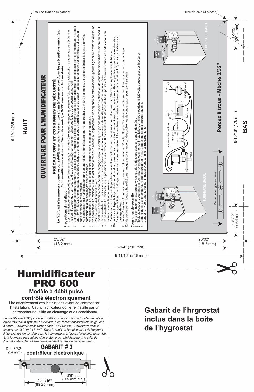
HumidificateurPRO 600
Lire attentivement ces instructions avant de commencer l'installation. Cet humidificateur doit être installé par un entrepreneur qualifié en chauffage et air conditionné.
PR
ÉC
AU
TIO
NS
ET
CO
NS
IGN
ES
DE
SÉ
CU
RIT
ÉLe
fabr
ican
t n'a
ssum
era
aucu
ne re
spon
sabi
lité
et la
gar
antie
ser
a nu
lle s
i l'in
stal
late
ur n
e pr
end
pas
les
préc
autio
ns s
uiva
ntes
.C
et h
umid
ifica
teur
est
un
mod
èle
à dé
bit p
ulsé
, il D
OIT
êtr
e ra
ccor
dé à
un
drai
n.Pr
écau
tions
d'in
stal
latio
n1-
C
et h
umid
ifica
teur
est
racc
ordé
à d
e l'e
au s
ous
pres
sion
et i
l doi
t être
inst
allé
de
faço
n à
ce q
u'un
e fu
ite d
'eau
acc
iden
telle
ne
caus
e pa
s de
dég
âts
à la
mai
son.
S'a
ssur
er q
ue le
s ra
ccor
ds d
'eau
son
t ins
tallé
s co
rrec
tem
ent,
sino
n de
s fu
ites
d'ea
u po
urra
ient
sur
veni
r.2-
C
et h
umid
ifica
teur
est
con
çu p
our ê
tre u
tilis
é su
r des
four
nais
es à
air
forc
é, d
e m
ême
que
des
four
nais
es m
ulti-
com
bust
ible
s do
nt la
tem
péra
ture
n'e
xcèd
e
pa
s 18
0°F
(82º
C).
Une
tem
péra
ture
sup
érie
ure
risqu
e d'
endo
mm
ager
vot
re h
umid
ifica
teur
et d
e ca
user
par
la s
uite
un
débo
rdem
ent d
'eau
qui
cau
sera
it
de
s do
mm
ages
à v
otre
mai
son.
3-
Ne
pas
inst
alle
r cet
hum
idifi
cate
ur d
ans
un e
ndro
it où
la te
mpé
ratu
re p
ourr
ait a
ppro
cher
32°
F (0
ºC) o
u m
oins
. Le
gel f
erai
t écl
ater
le tu
yau
d'ar
rivée
,
oc
casi
onna
nt a
insi
des
dég
âts
dans
la m
aiso
n.4-
N
e pa
s in
stal
ler l
'hum
idifi
cate
ur o
u le
col
let d
irect
emen
t sur
le c
orps
de
la fo
urna
ise.
5-
Ne
pas
inst
alle
r l'h
umid
ifica
teur
ou
le c
olle
t sur
le c
ôté
d'un
con
duit
où la
pré
senc
e d'
un s
erpe
ntin
de
refro
idis
sem
ent p
ourr
ait g
êner
ou
arrê
ter l
a ci
rcul
atio
n
d'
air a
u tra
vers
de
l'hum
idifi
cate
ur.
6-
Avan
t tou
te o
péra
tion
de d
écou
pe o
u de
per
çage
, tou
jour
s vé
rifie
r qu'
il n'
y a
pas
d'ac
cess
oire
éle
ctriq
ue o
u de
con
ditio
nnem
ent d
'air
en a
rriè
re d
u co
ndui
t.7-
N
e pa
s in
stal
ler l
'hum
idifi
cate
ur s
ur u
n co
ndui
t d'a
limen
tatio
n où
la p
ress
ion
stat
ique
dép
asse
0.4
" de
colo
nne
d'ea
u.8-
N
e pa
s in
stal
ler l
'hum
idifi
cate
ur s
i la
pres
sion
de
la v
ille
excè
de 9
0 ps
i car
des
effe
ts d
e co
up d
e bé
lier p
ourr
aien
t sur
veni
r. V
érifi
er le
s co
des
loca
ux e
n
m
atiè
re d
e ré
duct
ion
de p
ress
ion.
9-
L'in
stal
latio
n, le
câb
lage
et l
a pl
ombe
rie d
oive
nt s
e co
nfor
mer
aux
cod
es n
atio
naux
et l
ocau
x po
ur l'
élec
trici
té, l
a pl
ombe
rie e
t le
bâtim
ent.
10- L
e fil
de
câbl
age,
le tu
yau
d'al
imen
tatio
n et
le tu
yau
de d
rain
ne
doiv
ent p
as v
enir
en c
onta
ct a
vec
des
arêt
es c
oupa
ntes
ou
des
surfa
ces
chau
des.
S
'ass
urer
que
le tu
yau
de d
rain
age
n'a
pas
de c
oude
s, s
on e
xtré
mité
éta
nt b
ien
racc
ordé
e à
un d
rain
de
plan
cher
et q
u'il
n'y
a pa
s de
rési
stan
ce a
u
pass
age
de l'
eau.
11-
Le tr
ansf
orm
ateu
r fou
rni e
st p
révu
pou
r une
alim
enta
tion
à 12
0 vo
lts. N
e pa
s l'in
stal
ler s
ur u
ne fo
urna
ise
alim
enté
e so
us u
n au
tre v
olta
ge.
12- N
e pa
s ré
gler
le n
ivea
u d'
hum
idité
plu
s ha
ut q
ue re
com
man
dé c
ar d
es p
robl
èmes
de
cond
ensa
tion
pour
raie
nt s
urve
nir
Con
sign
es d
e sé
curit
é1-
Fa
ire b
ien
atte
ntio
n au
x ar
êtes
viv
es lo
rs d
e la
déc
oupe
dan
s un
con
duit
de m
étal
.2-
To
ujou
rs c
oupe
r le
cour
ant à
la fo
urna
ise
avan
t de
com
men
cer l
'inst
alla
tion.
Un
choc
éle
ctriq
ue à
120
vol
ts p
eut c
ause
r des
ble
ssur
es.
3-
L'ea
u ch
aude
à u
ne te
mpé
ratu
re s
upér
ieur
e à
125°
F (5
2ºC
) peu
t cau
ser d
es b
rûlu
res
sévè
res.
C
oupe
r l'a
rriv
ée d
'eau
au
robi
net p
rinci
pal a
vant
de
faire
les
racc
orde
men
ts.
Le modèle PRO 600 peut être installé au choix sur le conduit d'alimentation ou de retour d'un système à air chaud. Il est facilement réversible de gaucheà droite. Les dimensions totales sont: 15" x 15" x 9". L'ouverture dans le conduit est de 9-1/4" x 8-1/4". Dans le choix de l'emplacement de l'appareil, il faut prendre en considération les dimensions et l'accès facile pour le service.Si la fournaise est équipée d'un système de refroidissement, le volet de l'humidificateur devrait être fermé pendant la période de climatisation.
Modèle à débit pulsécontrôlé électroniquement
COND
UITD'A
IRCH
AUD
COND
UITDE
RETO
URCO
NDUIT
D'AIR
CHAU
D
COND
UITDE
RETO
URBlan
cNo
irco
ntrô
leur
éle
ctro
niqu
e
hydr
osta
t
32
valv
e
l'inte
rrupt
eur
24VA
CVA
LVE
HSA
055
trans
form
ateu
r
GABARIT # 3contrôleur électronique
Gabarit de l’hrgrostatinclus dans la boîte de l’hygrostat