dual address space & linkage stack -...
TRANSCRIPT
1
IBM Systems and Technology Group (STG)
© Copyright International Business Machines Corporation 2012
Dual Address Space &Linkage-Stack Architecture
Dan Greiner
z/Server Architecture
SHARE 118 in Atlanta
Session 10446, 12 March 2012, 4:30 pm
This presentation discusses two extremely powerful features of z/Architecture: the dual-address-space facility and the linkage stack.
I was interested in pursuing this topic for several years, and recently several factors influenced me to finally craft a presentation: (a) An associate from a past SHARE asked if I had such a topic, (b) a previous SHARE presentation by Kristine Harper discussed cross-memory communication, but did not delve into the hardware, (c) a colleague in my department wanted more information on the topic, and (d) Dr. John Ehrman (head of the SHARE Assembler Project) was looking for new content for SHARE 118 in Atlanta. How could I refuse?
This presentation is done as a part of the SHARE Assembler Project, which is well known for its “Assembler University” sessions including the popular Assembler Boot Camp (ABC). Using the university analogy where the ABC sessions represent entry-level undergraduate training, this session represents post-graduate-level material that is rather arcane. However, if you have the patience to muddle through this presentation (a) give yourself a pat on the back for perseverance, and (b) you will have an expert-level understanding of one of the features that distinguishes System z from other platforms. Note, for the purposes of brevity, this presentation does not provide all of the details of the operation of these features. For a complete understanding of this architecture, please refer to the z/Architecture Principles of Operation (SA22-7832).
In previous SHARE conferences, I have presented a topic on dynamic address translation (DAT) and access-register translation (ART). These topics are very closely related to the concept of the dual-address-space facility, and may be useful prerequisite reading.
This presentation was developed using PowerPoint, and makes extensive use of animation to illustrate the concepts (and, during a live presentation, to keep your eyes on the screen rather than your laptop). In these notes, the text [CLICK] indicates an advancement to the next animation on a slide.
Note, when submitted to the SHARE web site, the presentation is converted to a PDF, thus all of the animation is lost. If you would like a copy of the PowerPoint file, please see me after the session, or send me an e-mail to the address on the first slide.
2
2
The Legal Stuff
Trademarks:► The following terms are trademarks of the International Business Machines Corporation in the United States,
other countries, or both:– ESA/390– IBM– z/Architecture– z/OS– z/VM
► IEEE is a trademark of the Institute of Electrical and Electronics Engineers, Inc. in the United States, other countries, or both.
► Linux is a registered trademark of Linus Torvalds in the United States, other countries or both.► Unicode is a registered trademark of Unicode, Incorporated in the United States, other countries, or both.► Other trademarks and registered trademarks are the properties of their respective companies.
All information contained in this document is subject to change without notice. The products described in this document are not intended for use in applications such as implantation, life support, or other hazardous uses where malfunction could result in death, bodily injury or catastrophic property damage. The information contained in this document does not affect or change IBM product specifications or warranties. Nothing in this document shall operate as an express or implied license or indemnity under the intellectual property rights of IBM or third parties. All information contained in this document was obtained in specific environments, and is presented as an illustration. The results obtained in other operating environments may vary.While the information contained herein is believed to be accurate, such information is preliminary, and should not be relied upon for accuracy or completeness, and no representations or warranties of accuracy or completeness are made.The information in contained in this document is provided on an “AS IS” basis. In no event will IBM be liable for damages arising directly or indirectly from any use of the information contained in this document.
© Copyright International Business Machines Corporation 2012. Permission is granted to SHARE, Inc. to publish this presentation in the proceedings of SHARE 118.
3
3
Topics du Jour:
Review of architecture features exploited by Dual Address Space (DAS) and the Linkage-Stack (LS)
► Supervisor state, key-controlled protection
► Advanced-space facilities
Dual-address-space concepts and controls
Dual-address-space instructions
Linkage-stack concepts and controls
Linkage-stack instructions
Differences between basic and stacking PROGRAM CALL
Inventory of z/OS macros in support of DAS & LS
This slide is self explanatory.
4
4
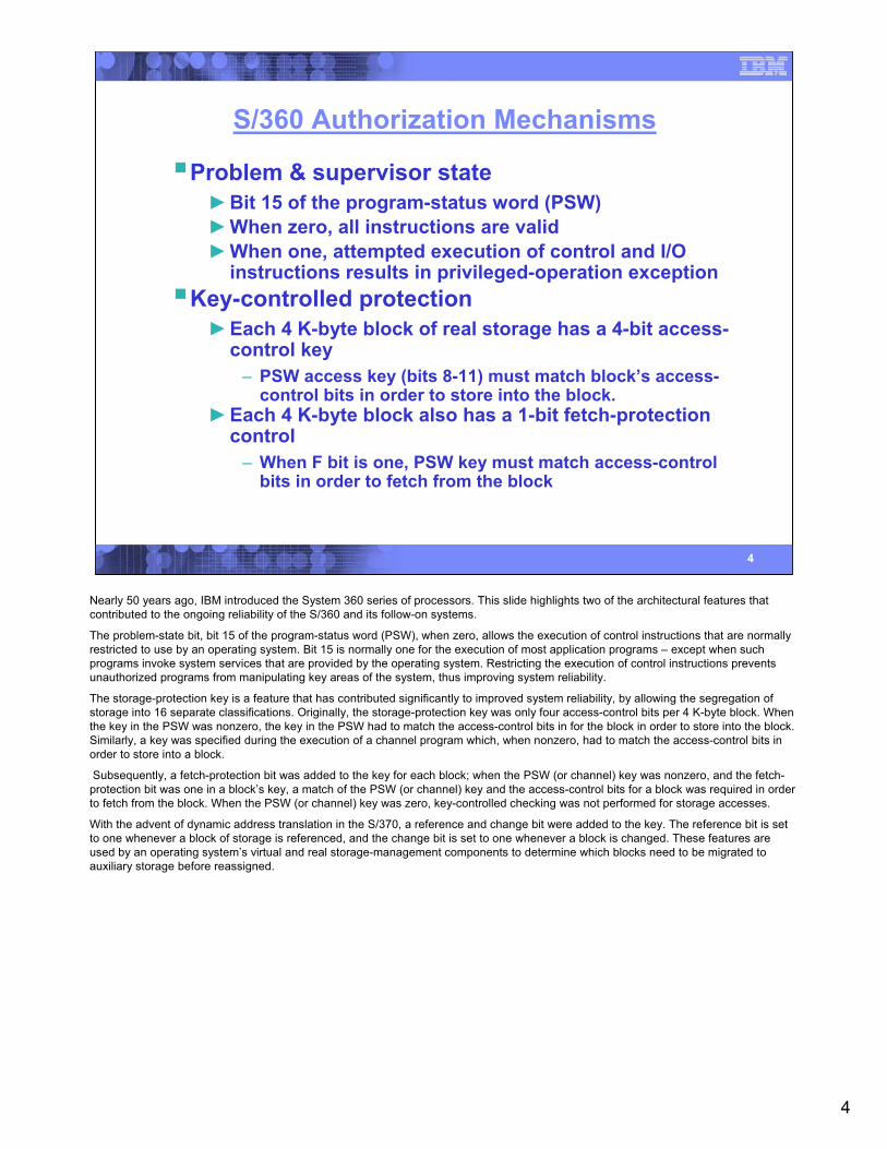
S/360 Authorization Mechanisms
Problem & supervisor state►Bit 15 of the program-status word (PSW)►When zero, all instructions are valid►When one, attempted execution of control and I/O
instructions results in privileged-operation exceptionKey-controlled protection►Each 4 K-byte block of real storage has a 4-bit access-
control key– PSW access key (bits 8-11) must match block’s access-
control bits in order to store into the block.►Each 4 K-byte block also has a 1-bit fetch-protection
control– When F bit is one, PSW key must match access-control
bits in order to fetch from the block
Nearly 50 years ago, IBM introduced the System 360 series of processors. This slide highlights two of the architectural features that contributed to the ongoing reliability of the S/360 and its follow-on systems.
The problem-state bit, bit 15 of the program-status word (PSW), when zero, allows the execution of control instructions that are normally restricted to use by an operating system. Bit 15 is normally one for the execution of most application programs – except when such programs invoke system services that are provided by the operating system. Restricting the execution of control instructions prevents unauthorized programs from manipulating key areas of the system, thus improving system reliability.
The storage-protection key is a feature that has contributed significantly to improved system reliability, by allowing the segregation of storage into 16 separate classifications. Originally, the storage-protection key was only four access-control bits per 4 K-byte block. When the key in the PSW was nonzero, the key in the PSW had to match the access-control bits in for the block in order to store into the block. Similarly, a key was specified during the execution of a channel program which, when nonzero, had to match the access-control bits in order to store into a block.
Subsequently, a fetch-protection bit was added to the key for each block; when the PSW (or channel) key was nonzero, and the fetch-protection bit was one in a block’s key, a match of the PSW (or channel) key and the access-control bits for a block was required in order to fetch from the block. When the PSW (or channel) key was zero, key-controlled checking was not performed for storage accesses.
With the advent of dynamic address translation in the S/370, a reference and change bit were added to the key. The reference bit is set to one whenever a block of storage is referenced, and the change bit is set to one whenever a block is changed. These features are used by an operating system’s virtual and real storage-management components to determine which blocks need to be migrated to auxiliary storage before reassigned.

5
5
Dynamic Address Translation (DAT, 1971)
DAT provides two fundamental features:►Over-commitment of real storage
– You can stuff terabytes of data into a gigabyte bag– OS manages paging to/from auxiliary storage – Reference and change bits added to the storage key in
support of virtual storage management►Segregation of data
– Program data is segregated into virtual address spaces– Control register 1 determines which address space is in
effect– Provides separation of one user’s data from another– Provides separation of key subsystem data from user
data
When dynamic address translation (DAT) was first introduced in the S/370, central storage was a precious commodity. DAT, in conjunction with paging by the operating system, provided the means by which a real storage could be over-commited, giving the illusion of having much more virtual storage than was actually installed in the machine.
However, another of the characteristics of DAT is perhaps more important – the ability to segregate data. This segregation can take the form of major subsystem components, or it may simply apply to keeping one user’s data apart from another’s. The S/360 architecture provided 16 storage keys for segregating data; DAT provides a much broader scope of segregation … literally thousands of address spaces can be managed.
Understanding this function of DAT – that is, the segregation of programs and data – is a key prerequisite for understanding the power of the dual-address-space functions described herein. Session 8192 from the San Jose SHARE in 2008 provides background information on DAT: http://proceedings.share.org/proceedings/
A powerful characteristic of DAT is the “D” in its acronym: it is dynamic. Control register 1 (CR1) contains a pointer to a set of translation tables used by the hardware to map virtual memory into real memory. With a single instruction, the operating system can reload CR1 to designate an entirely different virtual context … a different subsystem or user … or in the VM environment, a different virtual machine.
6
6
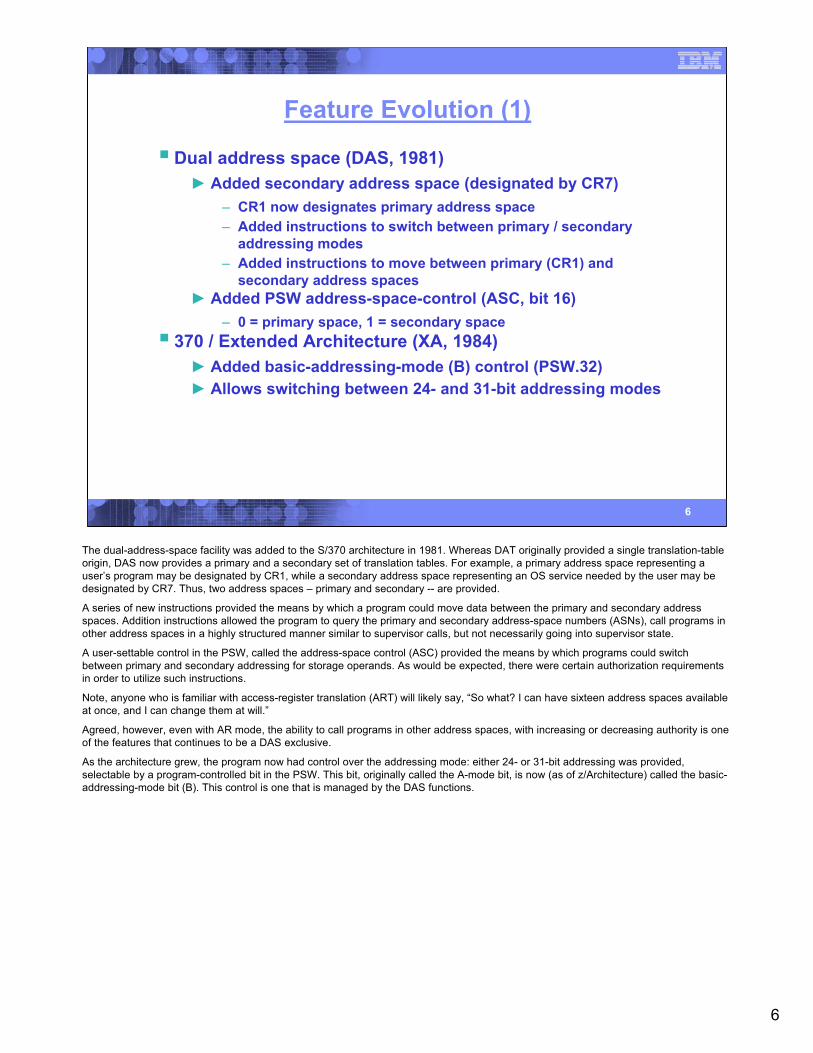
Feature Evolution (1)
Dual address space (DAS, 1981)► Added secondary address space (designated by CR7)
– CR1 now designates primary address space– Added instructions to switch between primary / secondary
addressing modes– Added instructions to move between primary (CR1) and
secondary address spaces► Added PSW address-space-control (ASC, bit 16)
– 0 = primary space, 1 = secondary space370 / Extended Architecture (XA, 1984)► Added basic-addressing-mode (B) control (PSW.32)► Allows switching between 24- and 31-bit addressing modes
The dual-address-space facility was added to the S/370 architecture in 1981. Whereas DAT originally provided a single translation-table origin, DAS now provides a primary and a secondary set of translation tables. For example, a primary address space representing a user’s program may be designated by CR1, while a secondary address space representing an OS service needed by the user may be designated by CR7. Thus, two address spaces – primary and secondary -- are provided.
A series of new instructions provided the means by which a program could move data between the primary and secondary address spaces. Addition instructions allowed the program to query the primary and secondary address-space numbers (ASNs), call programs in other address spaces in a highly structured manner similar to supervisor calls, but not necessarily going into supervisor state.
A user-settable control in the PSW, called the address-space control (ASC) provided the means by which programs could switch between primary and secondary addressing for storage operands. As would be expected, there were certain authorization requirements in order to utilize such instructions.
Note, anyone who is familiar with access-register translation (ART) will likely say, “So what? I can have sixteen address spaces available at once, and I can change them at will.”
Agreed, however, even with AR mode, the ability to call programs in other address spaces, with increasing or decreasing authority is one of the features that continues to be a DAS exclusive.
As the architecture grew, the program now had control over the addressing mode: either 24- or 31-bit addressing was provided, selectable by a program-controlled bit in the PSW. This bit, originally called the A-mode bit, is now (as of z/Architecture) called the basic-addressing-mode bit (B). This control is one that is managed by the DAS functions.
7
7
Feature Evolution (2)
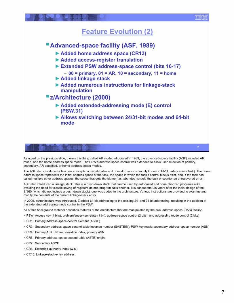
Advanced-space facility (ASF, 1989)►Added home address space (CR13)►Added access-register translation►Extended PSW address-space control (bits 16-17)
– 00 = primary, 01 = AR, 10 = secondary, 11 = home►Added linkage stack►Added numerous instructions for linkage-stack
manipulationz/Architecture (2000)►Added extended-addressing mode (E) control
(PSW.31)►Allows switching between 24/31-bit modes and 64-bit
mode
As noted on the previous slide, there’s this thing called AR mode. Introduced in 1989, the advanced-space facility (ASF) included AR mode, and the home address space mode. The PSW’s address-space control was extended to allow user selection of primary, secondary, AR-specified, or home address space modes.
The ASF also introduced a few new concepts: a dispatchable unit of work (more commonly known in MVS parlance as a task). The home address space represents the initial address space of the task, the space in which the task’s control blocks exist, and, if the task has called multiple other address spaces, the space that gets the blame (i.e., abended) should the task encounter an unrecovered error.
ASF also introduced a linkage stack. This is a push-down stack that can be used by authorized and nonauthorized programs alike, avoiding the need for classic saving of registers as one program calls another. It is curious that 25 years after the initial design of the S/360 (which did not include a push-down stack), one was added to the architecture. Various instructions are provided to examine and modify the contents of the current linkage-stack entry.
In 2000, z/Architecture was introduced. Z added 64-bit addressing to the existing 24- and 31-bit addressing, resulting in the addition of the extended-addressing-mode control in the PSW.
All of this background material describes features of the architecture that are manipulated by the dual-address-space (DAS) facility:
• PSW: Access key (4 bits), problem/supervisor-state (1 bit), address-space control (2 bits), and addressing mode control (2 bits)
• CR1: Primary address-space-control element (ASCE)
• CR3: Secondary address-space-second-table instance number (SASTEIN); PSW key mask; secondary address-space number (ASN)
• CR4: Primary ASTEIN; authorization index; primary ASN
• CR5: Primary address-space-second-table (ASTE) origin
• CR7: Secondary ASCE
• CR8: Extended-authority index (& al)
• CR15: Linkage-stack-entry address.
8
8
DAS Concepts:AddressSpace 1
AddressSpace 2
AddressSpace 3
AddressSpace 4
Program A
Program B
Program C Program D Program E
Program FProgram G
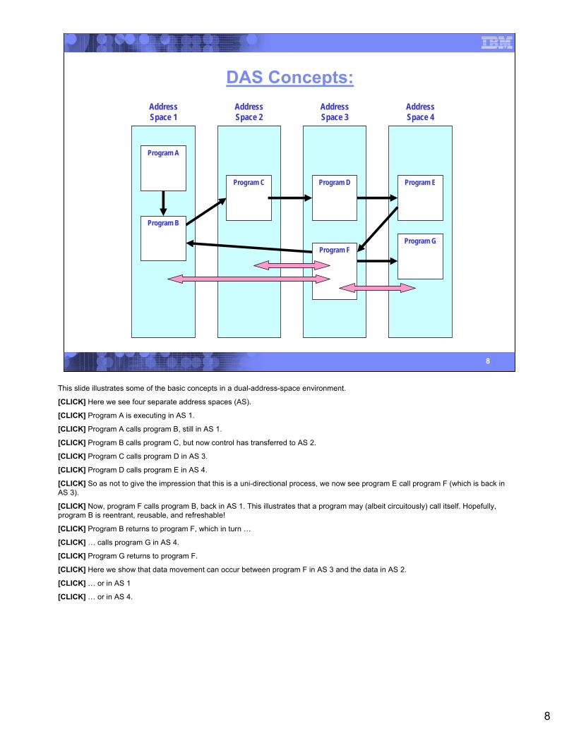
This slide illustrates some of the basic concepts in a dual-address-space environment.
[CLICK] Here we see four separate address spaces (AS).
[CLICK] Program A is executing in AS 1.
[CLICK] Program A calls program B, still in AS 1.
[CLICK] Program B calls program C, but now control has transferred to AS 2.
[CLICK] Program C calls program D in AS 3.
[CLICK] Program D calls program E in AS 4.
[CLICK] So as not to give the impression that this is a uni-directional process, we now see program E call program F (which is back in AS 3).
[CLICK] Now, program F calls program B, back in AS 1. This illustrates that a program may (albeit circuitously) call itself. Hopefully,program B is reentrant, reusable, and refreshable!
[CLICK] Program B returns to program F, which in turn …
[CLICK] … calls program G in AS 4.
[CLICK] Program G returns to program F.
[CLICK] Here we show that data movement can occur between program F in AS 3 and the data in AS 2.
[CLICK] … or in AS 1
[CLICK] … or in AS 4.
9
9
DAS Feature ControlsES A
CR 0: Miscellaneous controls
CR 3: Secondary-space controls, PKMSecondary ASTE Instance # (SASTEIN) * PSW Key Mask (PKM) Secondary ASN
Region-table, segment-table, or real-space-token origin GPSXR DTDLCR 1: Primary address-space control element (PASCE)
CR 4: Primary-space controls, AXPrimary ASTE Instance # (PASTEIN) * Authorization Index (AX) Primary ASN
Primary ASTE Origin (PASTEO)CR 5: Primary-ASN-Second-Table Origin
Region-table, segment-table, or real-space-token origin GPSXR DTDLCR 7: Secondary address-space control element (SASCE)
Region-table, segment-table, or real-space-token origin GPSXR DTDLCR 13: Home address-space control element (HASCE)
C AFTOCR 14: ASN-translation control & ASN 1st-table origin
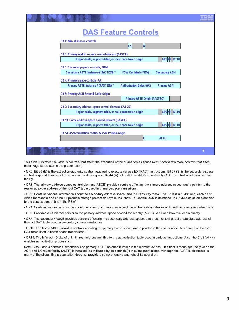
This slide illustrates the various controls that affect the execution of the dual-address space (we’ll show a few more controls that affect the linkage stack later in the presentation).
• CR0: Bit 36 (E) is the extraction-authority control, required to execute various EXTRACT instructions. Bit 37 (S) is the secondary-space control, required to access the secondary address space. Bit 44 (A) is the ASN-and-LX-reuse-facility (ALRF) control which enables the facility.
• CR1: The primary address-space control element (ASCE) provides controls affecting the primary address space, and a pointer to the real or absolute address of the root DAT table used in primary-space translations.
• CR3: Contains various information about the secondary address space, and the PSW key mask. The PKM is a 16-bit field, each bit of which represents one of the 16-possible storage-protection keys in the PSW. For certain DAS instructions, the PKM acts as an extension to the access-control bits in the PSW.
• CR4: Contains various information about the primary address space, and the authorization index used to authorize various instructions.
• CR5: Provides a 31-bit real pointer to the primary address-space second-table entry (ASTE). We’ll see how this works shortly.
• CR7: The secondary ASCE provides controls affecting the secondary address space, and a pointer to the real or absolute address of the root DAT table used in secondary-space translations.
• CR13: The home ASCE provides controls affecting the primary home space, and a pointer to the real or absolute address of the root DAT table used in home-space translations.
• CR14: The leftmost 19 bits of a 31-bit real address pointing to the authorization table used in various instructions. Also, the C bit (bit 44) enables authorization processing.
Note, CRs 3 and 4 contain a secondary and primary ASTE instance number in the leftmost 32 bits. This field is meaningful only when the ASN-and-LX-reuse facility (ALRF) is installed, as indicated by an asterisk (*) in subsequent slides. Although the ALRF is discussed in many of the slides, this presentation does not provide a comprehensive analysis of its operation.
10
10
DAS Instructions
EXTRACT PRIMARY ASN [AND INSTANCE]
EXTRACE SECONDARY ASN [AND INSTANCE]
INSERT ADDRESS SPACE CONTROL
INSERT PSW KEY
INSERT VIRTUAL STORAGE KEY
LOAD ADDRESS SPACE PARAMETERS
MOVE TO PRIMARY
MOVE TO SECONDARY
MOVE WITH KEY
PROGRAM CALL
PROGRAM TRANSFER [WITH INSTANCE]
SET ADDRESS SPACE CONTROL
SET SECONDARY ASN [WITH INSTANCE]
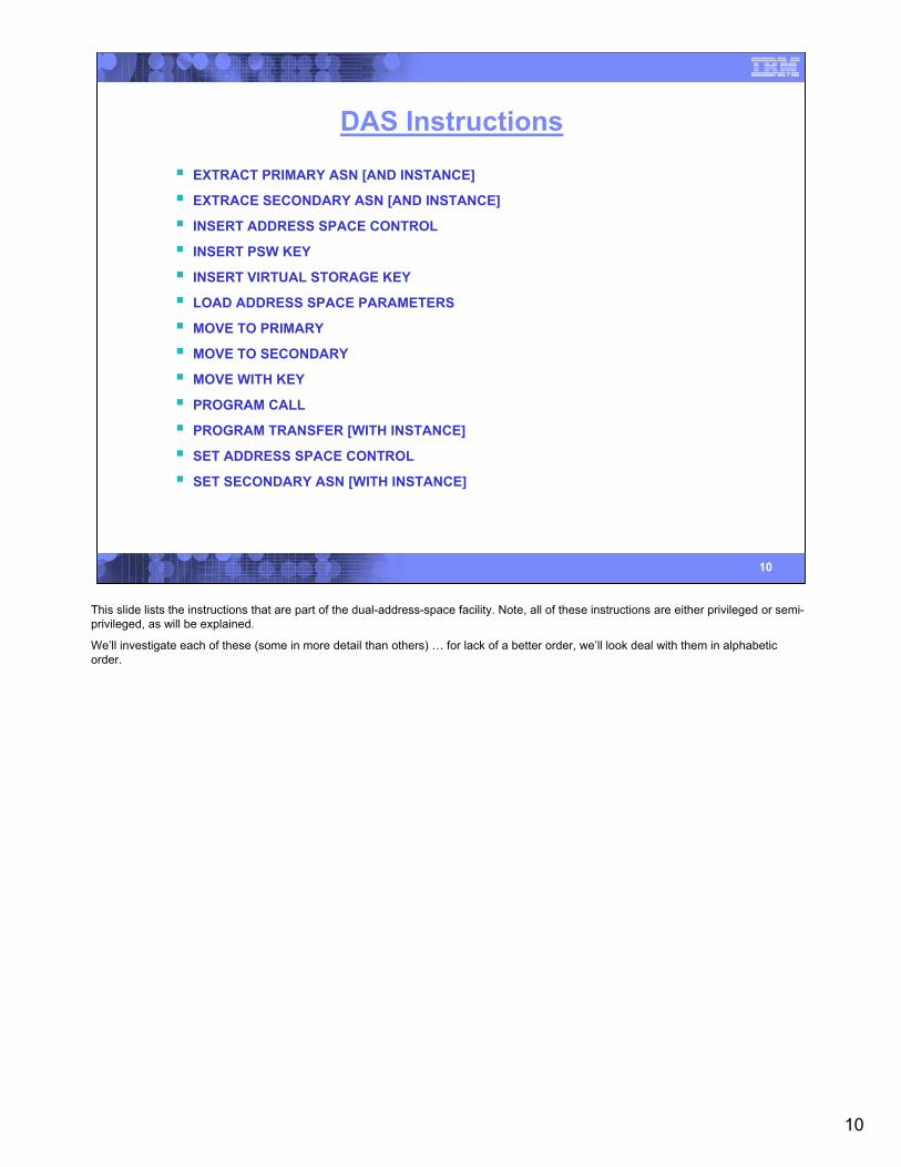
This slide lists the instructions that are part of the dual-address-space facility. Note, all of these instructions are either privileged or semi-privileged, as will be explained.
We’ll investigate each of these (some in more detail than others) … for lack of a better order, we’ll look deal with them in alphabetic order.
11
11
Extract Primary ASN
EPAR R1 [RRE]
‘B226’ / / / / / / / /0 16 24 31
/ / / /R128
CR 4:Primary ASTE Instance # (PASTEIN) * Authorization Index (AX) Primary ASN
R10
/ / / / / / / / / / / / / / / / / / / / / / / / / / / / / / / /32
0000 0000 0000 00006348
Primary ASN
Condition code: Unchanged Program exceptions:• Privileged-operation exception if extraction-authority
control (CR0.36) is zero in the problem state• Special-operation exception if DAT is off
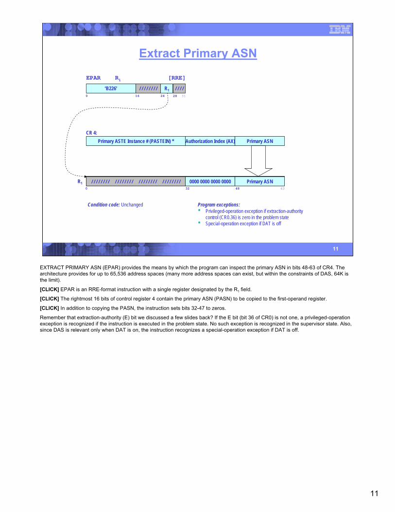
EXTRACT PRIMARY ASN (EPAR) provides the means by which the program can inspect the primary ASN in bits 48-63 of CR4. The architecture provides for up to 65,536 address spaces (many more address spaces can exist, but within the constraints of DAS, 64K is the limit).
[CLICK] EPAR is an RRE-format instruction with a single register designated by the R1 field.
[CLICK] The rightmost 16 bits of control register 4 contain the primary ASN (PASN) to be copied to the first-operand register.
[CLICK] In addition to copying the PASN, the instruction sets bits 32-47 to zeros.
Remember that extraction-authority (E) bit we discussed a few slides back? If the E bit (bit 36 of CR0) is not one, a privileged-operation exception is recognized if the instruction is executed in the problem state. No such exception is recognized in the supervisor state. Also, since DAS is relevant only when DAT is on, the instruction recognizes a special-operation exception if DAT is off.
12
12
Extract Primary ASN and Instance
EPAIR R1 [RRE]
‘B99A’ / / / / / / / /0 16 24 31
/ / / /R128
CR 4:Primary ASTE Instance # (PASTEIN) * Authorization Index (AX) Primary ASN
R10
PASTEIN32
0000 0000 0000 00006348
Primary ASN
Condition code: Unchanged Program exceptions:• Operation exception if ASN-and-LX-reuse facility not
installed• Privileged-operation exception if extraction-authority
control (CR0.36) is zero in the problem state• Special-operation exception if DAT is off
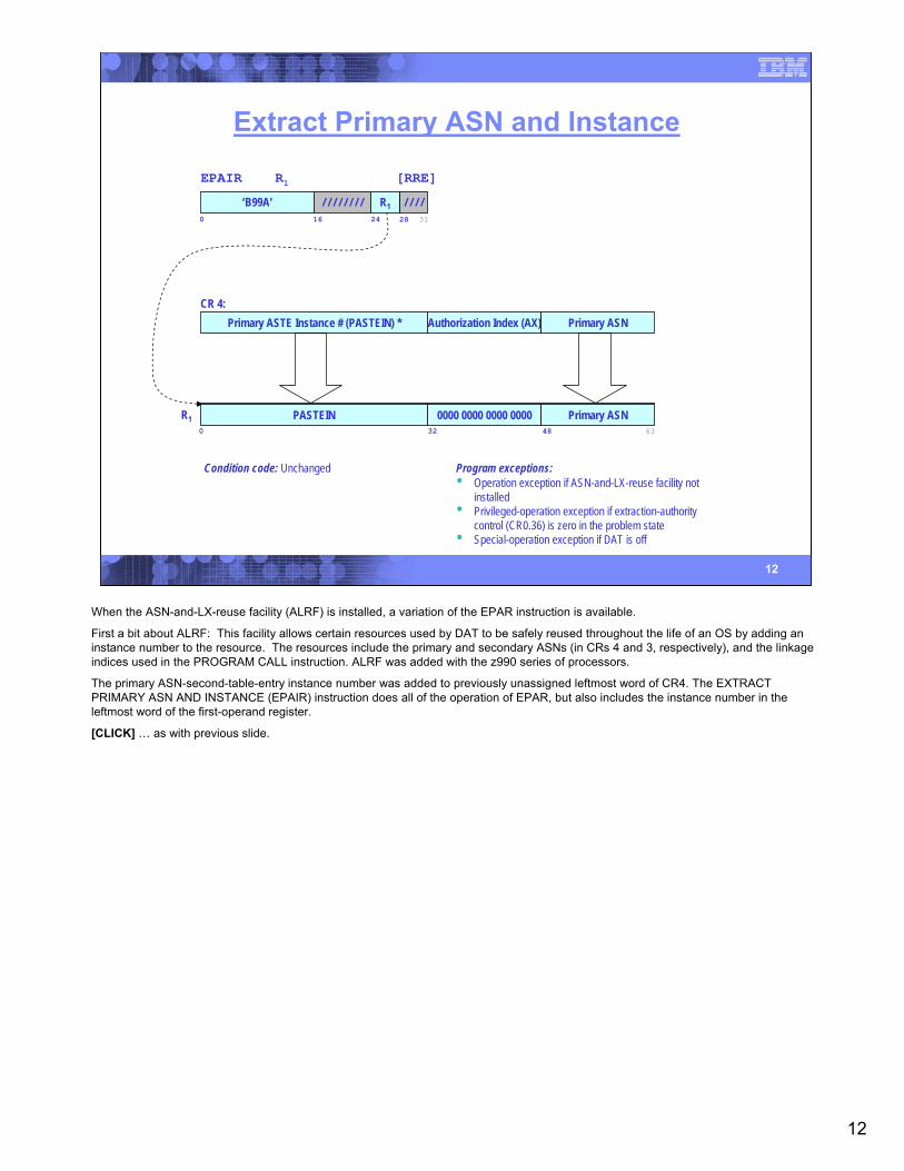
When the ASN-and-LX-reuse facility (ALRF) is installed, a variation of the EPAR instruction is available.
First a bit about ALRF: This facility allows certain resources used by DAT to be safely reused throughout the life of an OS by adding an instance number to the resource. The resources include the primary and secondary ASNs (in CRs 4 and 3, respectively), and the linkage indices used in the PROGRAM CALL instruction. ALRF was added with the z990 series of processors.
The primary ASN-second-table-entry instance number was added to previously unassigned leftmost word of CR4. The EXTRACT PRIMARY ASN AND INSTANCE (EPAIR) instruction does all of the operation of EPAR, but also includes the instance number in the leftmost word of the first-operand register.
[CLICK] … as with previous slide.
13
13
Extract Secondary ASN
ESAR R1 [RRE]
‘B227’ / / / / / / / /0 16 24 31
/ / / /R128
CR 3:Secondary ASTE Instance # (SASTEIN) * PSW Key Mask Secondary ASN
R10
/ / / / / / / / / / / / / / / / / / / / / / / / / / / / / / / /32
0000 0000 0000 00006348
Secondary ASN
Condition code: Unchanged Program exceptions:• Privileged-operation exception if extraction-authority
control (CR0.36) is zero in the problem state• Special-operation exception if DAT is off
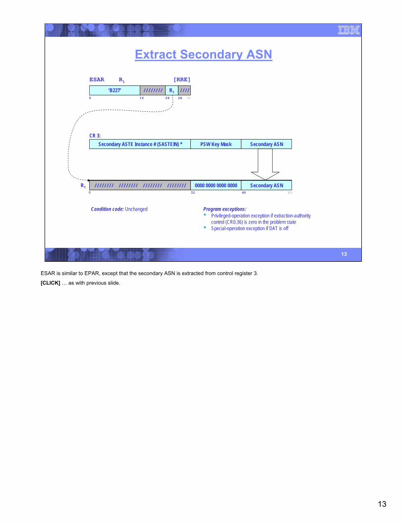
ESAR is similar to EPAR, except that the secondary ASN is extracted from control register 3.
[CLICK] … as with previous slide.
14
14
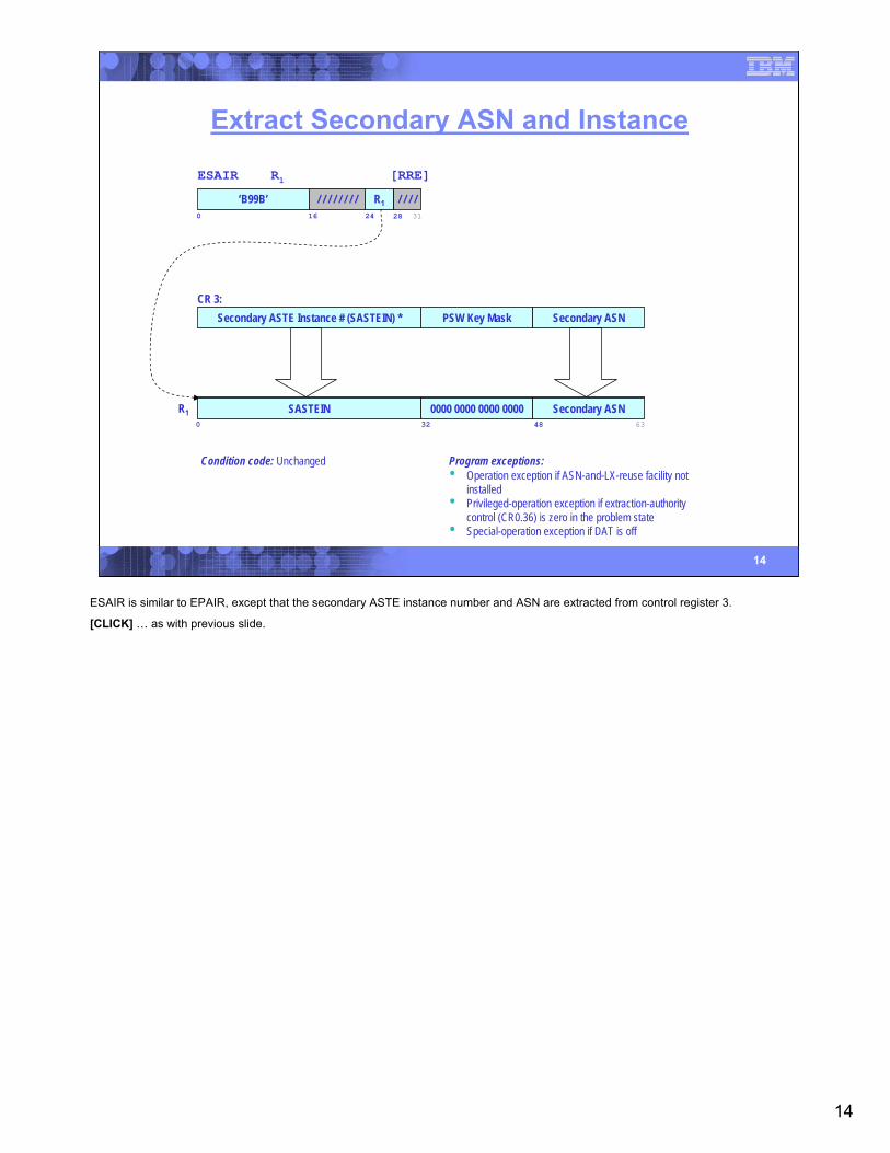
Extract Secondary ASN and Instance
ESAIR R1 [RRE]
‘B99B’ / / / / / / / /0 16 24 31
/ / / /R128
CR 3:Secondary ASTE Instance # (SASTEIN) * PSW Key Mask Secondary ASN
R10
SASTEIN32
0000 0000 0000 00006348
Secondary ASN
Condition code: Unchanged Program exceptions:• Operation exception if ASN-and-LX-reuse facility not
installed• Privileged-operation exception if extraction-authority
control (CR0.36) is zero in the problem state• Special-operation exception if DAT is off
ESAIR is similar to EPAIR, except that the secondary ASTE instance number and ASN are extracted from control register 3.
[CLICK] … as with previous slide.
15
15
Insert Address Space Control
IAC R1 [RRE]
‘B224’ / / / / / / / /0 16 24 31
/ / / /R128
R10
/ / / / / / / / / / / / / / / / / / / / / / / / / / / / / / / / / / / / / / / / / / / / / / / / 00000048
PSW:0R 000 T I E Key 0MWPAS MaskCC 0000000 EA 0000000 00000000 00000000 00000000 …
54
SA63
/ / / / / / / /56
Condition code:0 Primary-space mode1 Secondary-space mode2 AR mode3 Home-space mode
Program exceptions:• Privileged-operation exception if extraction-authority
control (CR0.36) is zero in the problem state• Special-operation exception if DAT is off
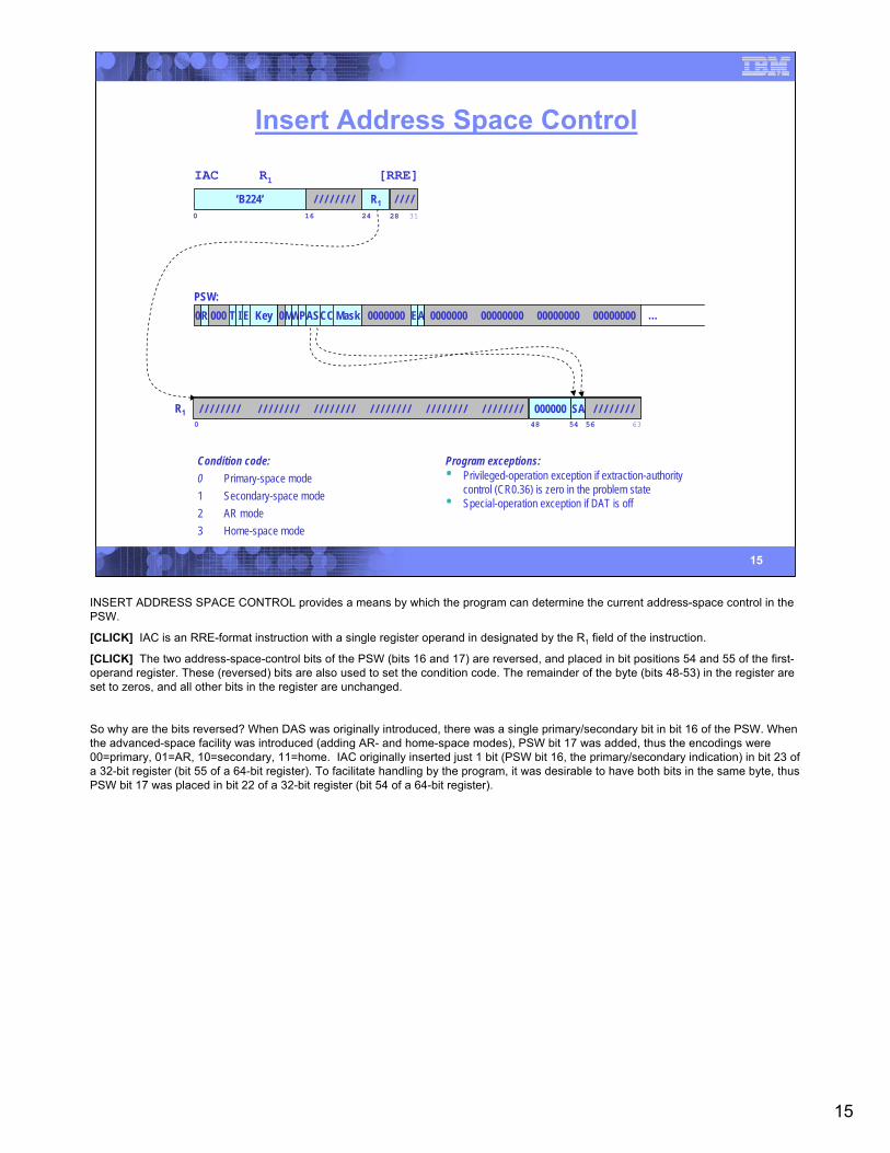
INSERT ADDRESS SPACE CONTROL provides a means by which the program can determine the current address-space control in the PSW.
[CLICK] IAC is an RRE-format instruction with a single register operand in designated by the R1 field of the instruction.
[CLICK] The two address-space-control bits of the PSW (bits 16 and 17) are reversed, and placed in bit positions 54 and 55 of the first-operand register. These (reversed) bits are also used to set the condition code. The remainder of the byte (bits 48-53) in the register are set to zeros, and all other bits in the register are unchanged.
So why are the bits reversed? When DAS was originally introduced, there was a single primary/secondary bit in bit 16 of the PSW. When the advanced-space facility was introduced (adding AR- and home-space modes), PSW bit 17 was added, thus the encodings were 00=primary, 01=AR, 10=secondary, 11=home. IAC originally inserted just 1 bit (PSW bit 16, the primary/secondary indication) in bit 23 of a 32-bit register (bit 55 of a 64-bit register). To facilitate handling by the program, it was desirable to have both bits in the same byte, thus PSW bit 17 was placed in bit 22 of a 32-bit register (bit 54 of a 64-bit register).
16
16
Insert PSW Key
IPK [S]
‘B20B’ / / / / / / / / / / / / / / / /0 16 31
GR2 / / / / / / / / / / / / / / / / / / / / / / / / / / / / / / / / / / / / / / / / / / / / / / / / / / / / / / / / / / / / / / / /0
PSW:0R 000 T I E Key 0MWPAS MaskCC 0000000 EA 0000000 00000000 00000000 00000000 …
0000Key56 60 63
Condition code: Unchanged Program exceptions:• Privileged-operation exception if extraction-authority
control (CR0.36) is zero in the problem state
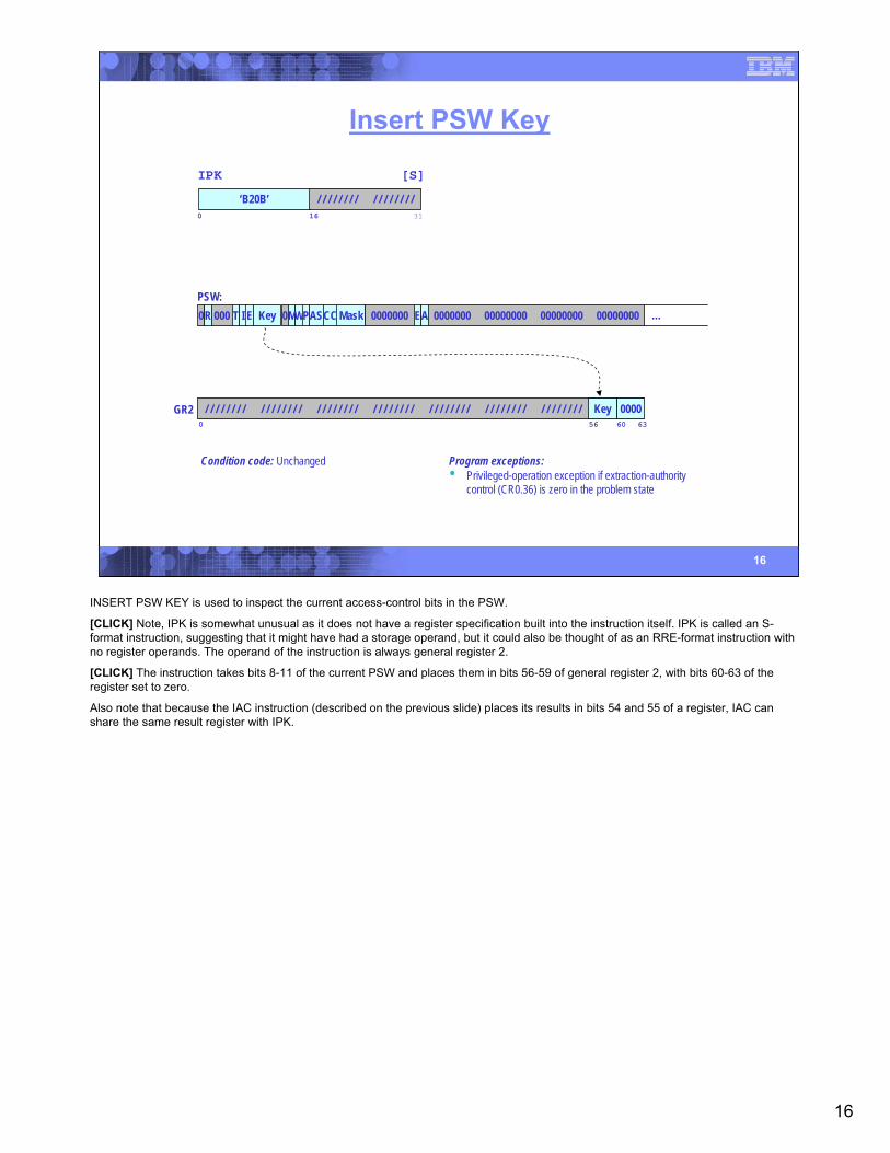
INSERT PSW KEY is used to inspect the current access-control bits in the PSW.
[CLICK] Note, IPK is somewhat unusual as it does not have a register specification built into the instruction itself. IPK is called an S-format instruction, suggesting that it might have had a storage operand, but it could also be thought of as an RRE-format instruction with no register operands. The operand of the instruction is always general register 2.
[CLICK] The instruction takes bits 8-11 of the current PSW and places them in bits 56-59 of general register 2, with bits 60-63 of the register set to zero.
Also note that because the IAC instruction (described on the previous slide) places its results in bits 54 and 55 of a register, IAC can share the same result register with IPK.
17
17
Insert Virtual Storage Key
IVSK R1,R2 [RRE]
R10
/ / / / / / / / / / / / / / / / / / / / / / / / / / / / / / / / / / / / / / / / / / / / / / / / / / / / / / / /
Condition code: Unchanged Program exceptions:• Privileged-operation exception if extraction-authority
control (CR0.36) is zero in the problem state• Special-operation exception if DAT is off
‘B223’ / / / / / / / /0 16 31
R1 R224 28 4 K-byte Page
in Virtual Storage
FRCACC
Storage KeyFor Block
000ACC56 60 63
F
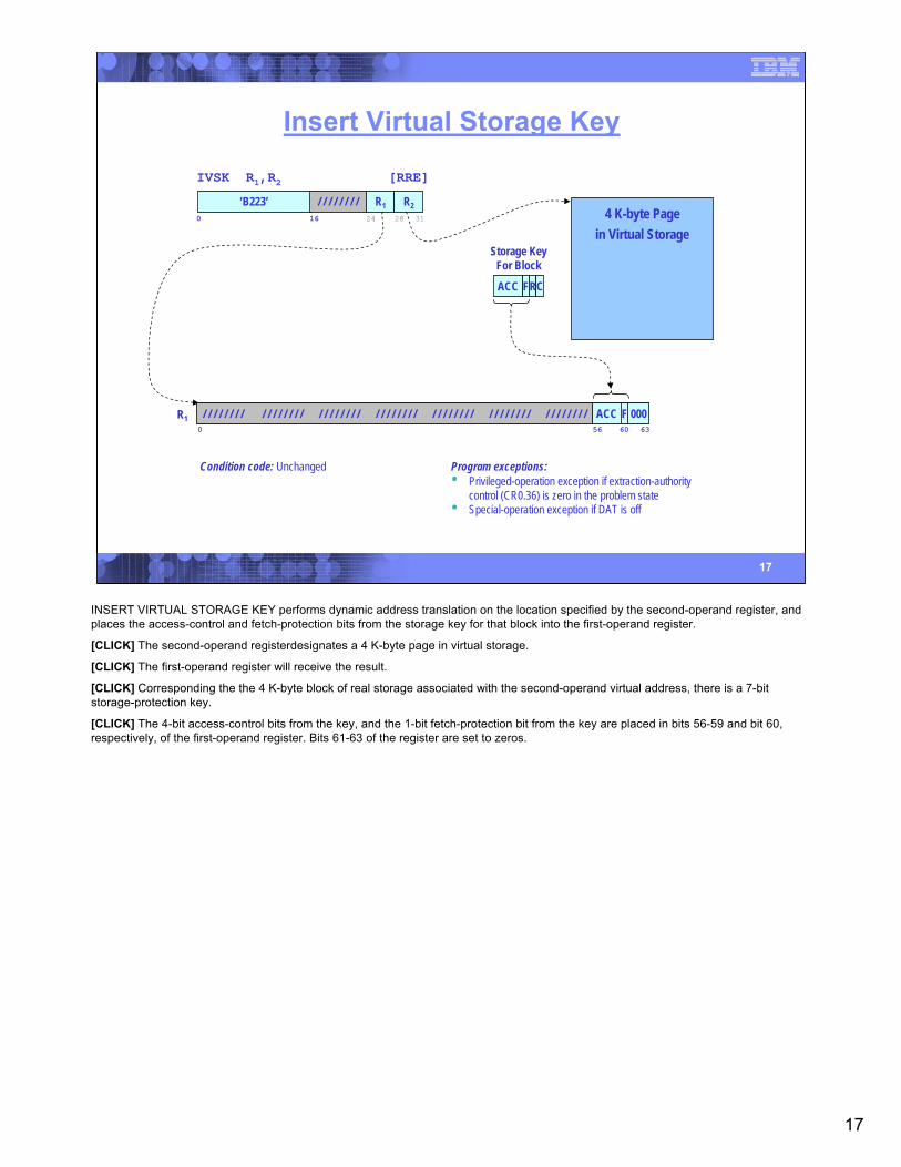
INSERT VIRTUAL STORAGE KEY performs dynamic address translation on the location specified by the second-operand register, and places the access-control and fetch-protection bits from the storage key for that block into the first-operand register.
[CLICK] The second-operand registerdesignates a 4 K-byte page in virtual storage.
[CLICK] The first-operand register will receive the result.
[CLICK] Corresponding the the 4 K-byte block of real storage associated with the second-operand virtual address, there is a 7-bit storage-protection key.
[CLICK] The 4-bit access-control bits from the key, and the 1-bit fetch-protection bit from the key are placed in bits 56-59 and bit 60, respectively, of the first-operand register. Bits 61-63 of the register are set to zeros.
18
18
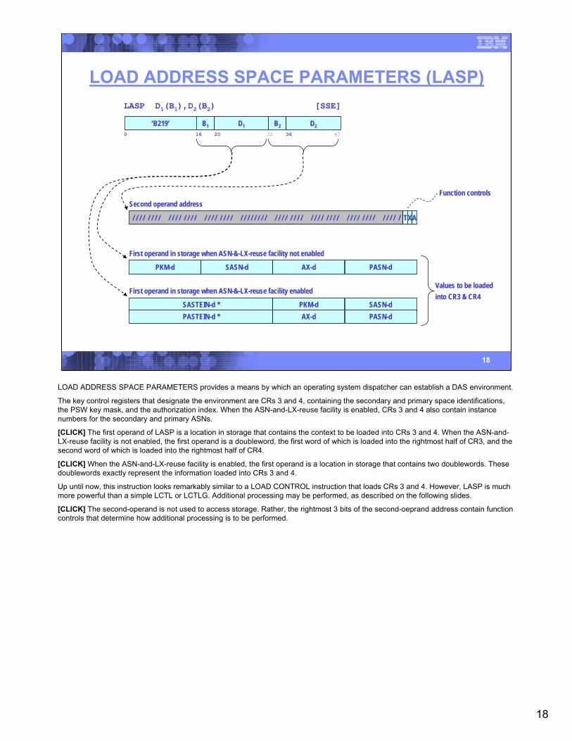
LOAD ADDRESS SPACE PARAMETERS (LASP)
First operand in storage when ASN-&-LX-reuse facility enabled
SASTEIN-d * PKM-d SASN-dPASTEIN-d * AX-d PASN-d
LASP D1(B1),D2(B2) [SSE]
0 16 20 32‘B219’ B1 D1 B2 D2
36 47
PKM-d SASN-d AX-d PASN-d
First operand in storage when ASN-&-LX-reuse facility not enabled
Second operand address
/ / / / / / / / / / / / / / / / / / / / / / / / / / / / / / / / / / / / / / / / / / / / / / / / / / / / / / / / / / / / / TXA
Values to be loadedinto CR3 & CR4
Function controls
LOAD ADDRESS SPACE PARAMETERS provides a means by which an operating system dispatcher can establish a DAS environment.
The key control registers that designate the environment are CRs 3 and 4, containing the secondary and primary space identifications, the PSW key mask, and the authorization index. When the ASN-and-LX-reuse facility is enabled, CRs 3 and 4 also contain instance numbers for the secondary and primary ASNs.
[CLICK] The first operand of LASP is a location in storage that contains the context to be loaded into CRs 3 and 4. When the ASN-and-LX-reuse facility is not enabled, the first operand is a doubleword, the first word of which is loaded into the rightmost half of CR3, and the second word of which is loaded into the rightmost half of CR4.
[CLICK] When the ASN-and-LX-reuse facility is enabled, the first operand is a location in storage that contains two doublewords. These doublewords exactly represent the information loaded into CRs 3 and 4.
Up until now, this instruction looks remarkably similar to a LOAD CONTROL instruction that loads CRs 3 and 4. However, LASP is much more powerful than a simple LCTL or LCTLG. Additional processing may be performed, as described on the following slides.
[CLICK] The second-operand is not used to access storage. Rather, the rightmost 3 bits of the second-oeprand address contain function controls that determine how additional processing is to be performed.
19
19
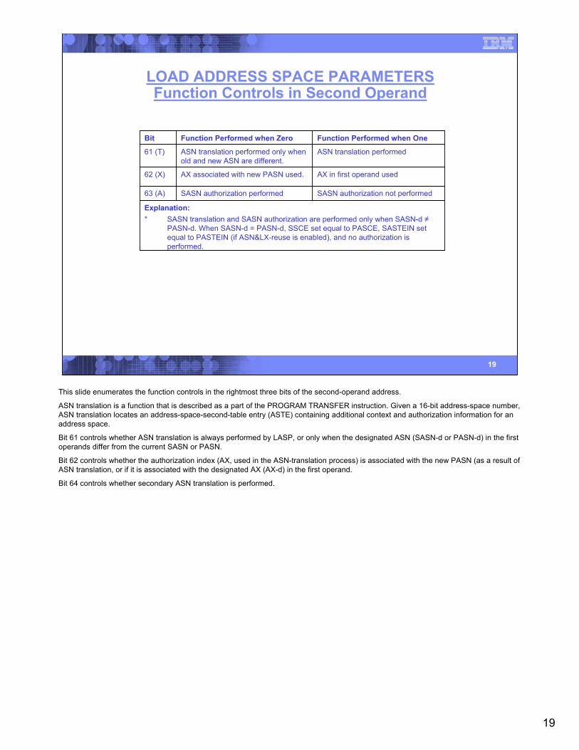
LOAD ADDRESS SPACE PARAMETERSFunction Controls in Second Operand
Explanation:* SASN translation and SASN authorization are performed only when SASN-d ≠
PASN-d. When SASN-d = PASN-d, SSCE set equal to PASCE, SASTEIN set equal to PASTEIN (if ASN&LX-reuse is enabled), and no authorization is performed.
SASN authorization not performedSASN authorization performed63 (A)
AX in first operand usedAX associated with new PASN used.62 (X)
ASN translation performedASN translation performed only when old and new ASN are different.
61 (T)
Function Performed when OneFunction Performed when ZeroBit
This slide enumerates the function controls in the rightmost three bits of the second-operand address.
ASN translation is a function that is described as a part of the PROGRAM TRANSFER instruction. Given a 16-bit address-space number, ASN translation locates an address-space-second-table entry (ASTE) containing additional context and authorization information for an address space.
Bit 61 controls whether ASN translation is always performed by LASP, or only when the designated ASN (SASN-d or PASN-d) in the first operands differ from the current SASN or PASN.
Bit 62 controls whether the authorization index (AX, used in the ASN-translation process) is associated with the new PASN (as a result of ASN translation, or if it is associated with the designated AX (AX-d) in the first operand.
Bit 64 controls whether secondary ASN translation is performed.
20
20
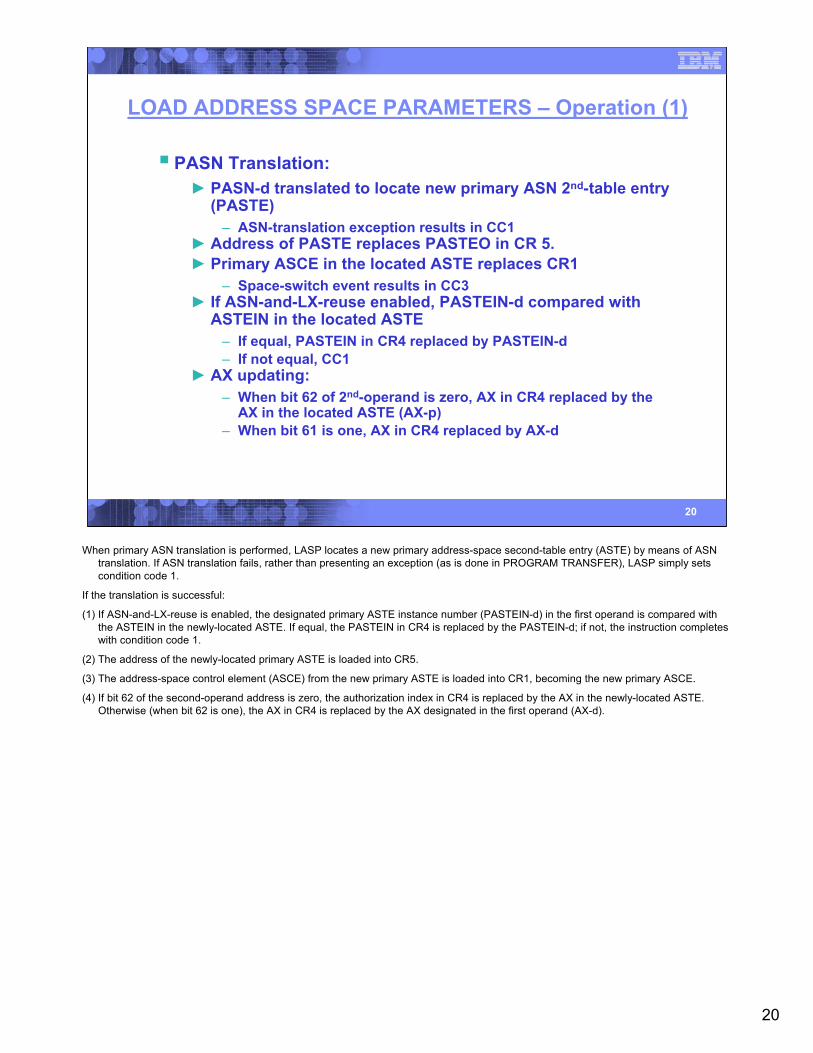
LOAD ADDRESS SPACE PARAMETERS – Operation (1)
PASN Translation:► PASN-d translated to locate new primary ASN 2nd-table entry
(PASTE)– ASN-translation exception results in CC1
► Address of PASTE replaces PASTEO in CR 5.► Primary ASCE in the located ASTE replaces CR1
– Space-switch event results in CC3► If ASN-and-LX-reuse enabled, PASTEIN-d compared with
ASTEIN in the located ASTE– If equal, PASTEIN in CR4 replaced by PASTEIN-d– If not equal, CC1
► AX updating:– When bit 62 of 2nd-operand is zero, AX in CR4 replaced by the
AX in the located ASTE (AX-p)– When bit 61 is one, AX in CR4 replaced by AX-d
When primary ASN translation is performed, LASP locates a new primary address-space second-table entry (ASTE) by means of ASN translation. If ASN translation fails, rather than presenting an exception (as is done in PROGRAM TRANSFER), LASP simply sets condition code 1.
If the translation is successful:
(1) If ASN-and-LX-reuse is enabled, the designated primary ASTE instance number (PASTEIN-d) in the first operand is compared with the ASTEIN in the newly-located ASTE. If equal, the PASTEIN in CR4 is replaced by the PASTEIN-d; if not, the instruction completes with condition code 1.
(2) The address of the newly-located primary ASTE is loaded into CR5.
(3) The address-space control element (ASCE) from the new primary ASTE is loaded into CR1, becoming the new primary ASCE.
(4) If bit 62 of the second-operand address is zero, the authorization index in CR4 is replaced by the AX in the newly-located ASTE. Otherwise (when bit 62 is one), the AX in CR4 is replaced by the AX designated in the first operand (AX-d).
21
21
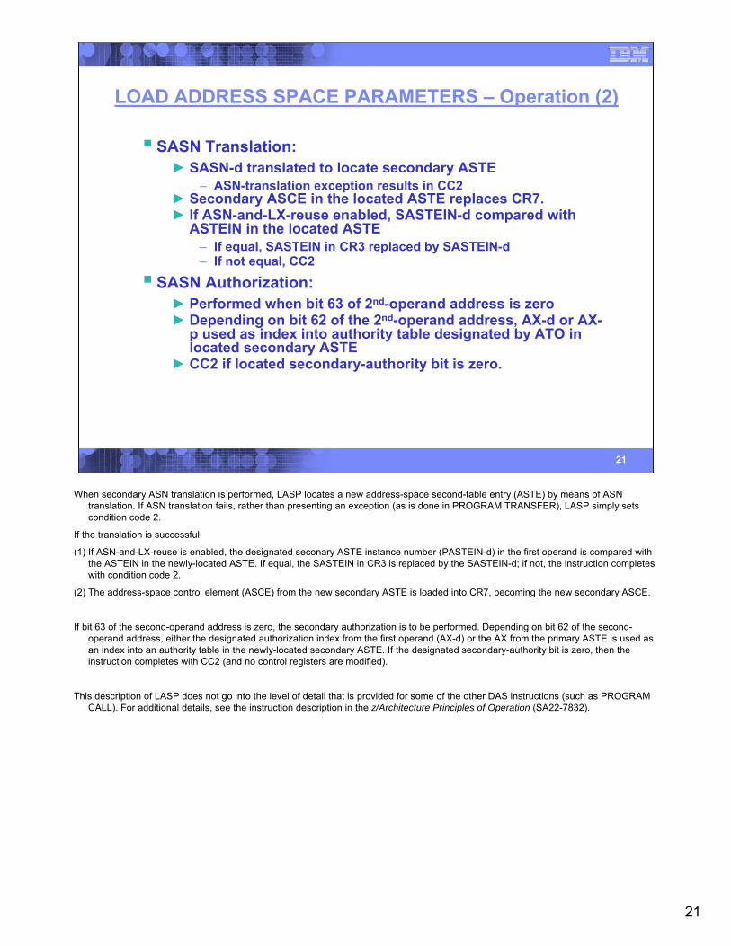
LOAD ADDRESS SPACE PARAMETERS – Operation (2)
SASN Translation:► SASN-d translated to locate secondary ASTE
– ASN-translation exception results in CC2► Secondary ASCE in the located ASTE replaces CR7.► If ASN-and-LX-reuse enabled, SASTEIN-d compared with
ASTEIN in the located ASTE– If equal, SASTEIN in CR3 replaced by SASTEIN-d– If not equal, CC2
SASN Authorization:► Performed when bit 63 of 2nd-operand address is zero► Depending on bit 62 of the 2nd-operand address, AX-d or AX-
p used as index into authority table designated by ATO in located secondary ASTE
► CC2 if located secondary-authority bit is zero.
When secondary ASN translation is performed, LASP locates a new address-space second-table entry (ASTE) by means of ASN translation. If ASN translation fails, rather than presenting an exception (as is done in PROGRAM TRANSFER), LASP simply sets condition code 2.
If the translation is successful:
(1) If ASN-and-LX-reuse is enabled, the designated seconary ASTE instance number (PASTEIN-d) in the first operand is compared with the ASTEIN in the newly-located ASTE. If equal, the SASTEIN in CR3 is replaced by the SASTEIN-d; if not, the instruction completes with condition code 2.
(2) The address-space control element (ASCE) from the new secondary ASTE is loaded into CR7, becoming the new secondary ASCE.
If bit 63 of the second-operand address is zero, the secondary authorization is to be performed. Depending on bit 62 of the second-operand address, either the designated authorization index from the first operand (AX-d) or the AX from the primary ASTE is used as an index into an authority table in the newly-located secondary ASTE. If the designated secondary-authority bit is zero, then the instruction completes with CC2 (and no control registers are modified).
This description of LASP does not go into the level of detail that is provided for some of the other DAS instructions (such as PROGRAM CALL). For additional details, see the instruction description in the z/Architecture Principles of Operation (SA22-7832).
22
22
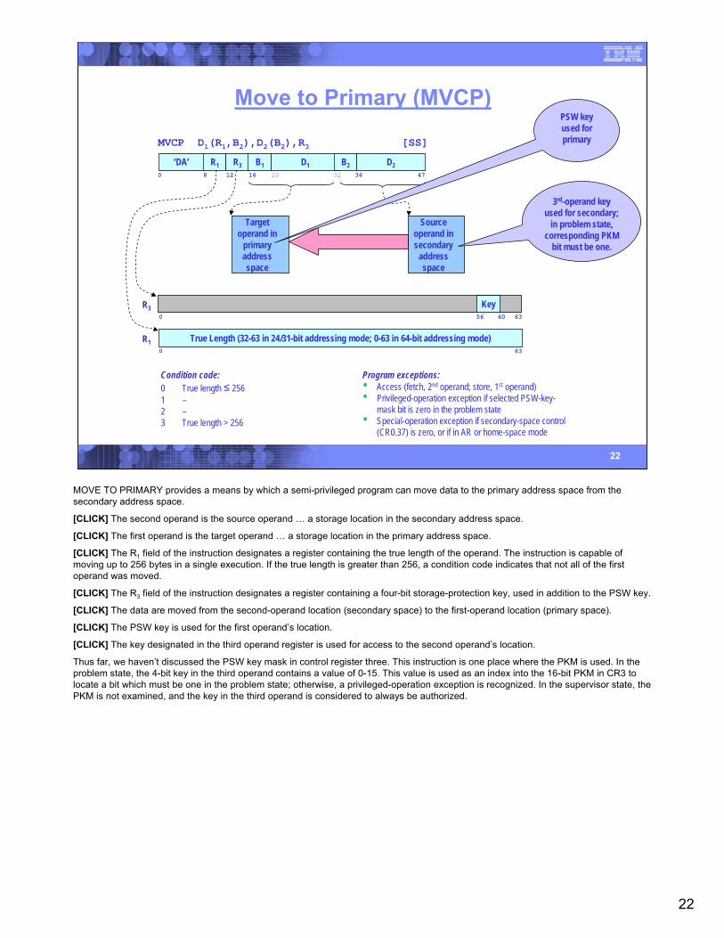
Move to Primary (MVCP)
MVCP D1(R1,B2),D2(B2),R3 [SS]
Condition code:0 True length ≤ 2561 –2 –3 True length > 256
Program exceptions:• Access (fetch, 2nd operand; store, 1st operand)• Privileged-operation exception if selected PSW-key-
mask bit is zero in the problem state• Special-operation exception if secondary-space control
(CR0.37) is zero, or if in AR or home-space mode
Sourceoperand insecondary
addressspace
‘DA’0 16 32
R1 R320
B1 D1 B2 D28 12 36 47
True Length (32-63 in 24/31-bit addressing mode; 0-63 in 64-bit addressing mode)R10 63
R30 56 60 63
Key
3rd-operand key used for secondary;
in problem state, corresponding PKM
bit must be one.
Targetoperand in
primaryaddressspace
PSW key used for primary
MOVE TO PRIMARY provides a means by which a semi-privileged program can move data to the primary address space from the secondary address space.
[CLICK] The second operand is the source operand … a storage location in the secondary address space.
[CLICK] The first operand is the target operand … a storage location in the primary address space.
[CLICK] The R1 field of the instruction designates a register containing the true length of the operand. The instruction is capable of moving up to 256 bytes in a single execution. If the true length is greater than 256, a condition code indicates that not all of the first operand was moved.
[CLICK] The R3 field of the instruction designates a register containing a four-bit storage-protection key, used in addition to the PSW key.
[CLICK] The data are moved from the second-operand location (secondary space) to the first-operand location (primary space).
[CLICK] The PSW key is used for the first operand’s location.
[CLICK] The key designated in the third operand register is used for access to the second operand’s location.
Thus far, we haven’t discussed the PSW key mask in control register three. This instruction is one place where the PKM is used. In the problem state, the 4-bit key in the third operand contains a value of 0-15. This value is used as an index into the 16-bit PKM in CR3 to locate a bit which must be one in the problem state; otherwise, a privileged-operation exception is recognized. In the supervisor state, the PKM is not examined, and the key in the third operand is considered to always be authorized.
23
23
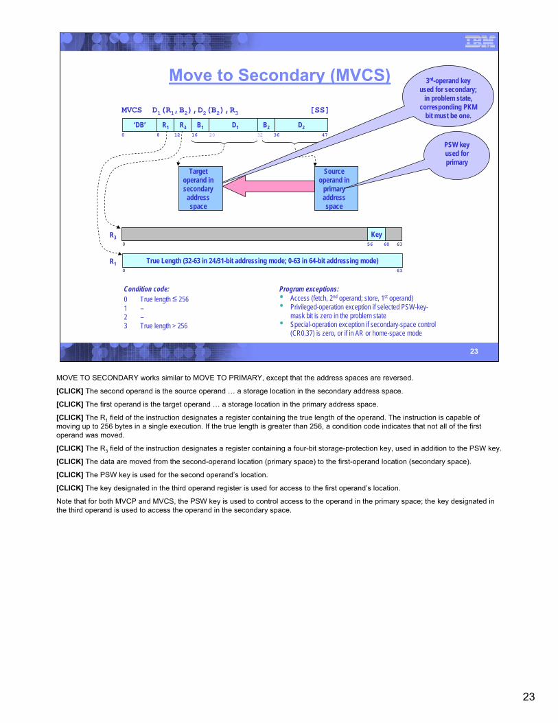
Move to Secondary (MVCS)
MVCS D1(R1,B2),D2(B2),R3 [SS]
Condition code:0 True length ≤ 2561 –2 –3 True length > 256
Program exceptions:• Access (fetch, 2nd operand; store, 1st operand)• Privileged-operation exception if selected PSW-key-
mask bit is zero in the problem state• Special-operation exception if secondary-space control
(CR0.37) is zero, or if in AR or home-space mode
Sourceoperand in
primaryaddressspace
‘DB’0 16 32
R1 R320
B1 D1 B2 D28 12 36 47
True Length (32-63 in 24/31-bit addressing mode; 0-63 in 64-bit addressing mode)R10 63
R30 56 60 63
Key
3rd-operand key used for secondary;
in problem state, corresponding PKM
bit must be one.
Targetoperand insecondary
addressspace
PSW key used for primary
MOVE TO SECONDARY works similar to MOVE TO PRIMARY, except that the address spaces are reversed.
[CLICK] The second operand is the source operand … a storage location in the secondary address space.
[CLICK] The first operand is the target operand … a storage location in the primary address space.
[CLICK] The R1 field of the instruction designates a register containing the true length of the operand. The instruction is capable of moving up to 256 bytes in a single execution. If the true length is greater than 256, a condition code indicates that not all of the first operand was moved.
[CLICK] The R3 field of the instruction designates a register containing a four-bit storage-protection key, used in addition to the PSW key.
[CLICK] The data are moved from the second-operand location (primary space) to the first-operand location (secondary space).
[CLICK] The PSW key is used for the second operand’s location.
[CLICK] The key designated in the third operand register is used for access to the first operand’s location.
Note that for both MVCP and MVCS, the PSW key is used to control access to the operand in the primary space; the key designated in the third operand is used to access the operand in the secondary space.
24
24
MVCP / MVCS ExampleAddressSpace 1
AddressSpace 2
AddressSpace 3
AddressSpace 4
Program A
Program B
Program C Program D Program E
Program F
MVCP
MVCS
(primary)
(secondary)
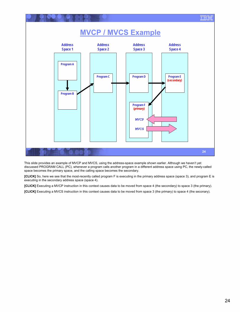
This slide provides an example of MVCP and MVCS, using the address-space example shown earlier. Although we haven’t yet discussed PROGRAM CALL (PC), whenever a program calls another program in a different address space using PC, the newly-called space becomes the primary space, and the calling space becomes the secondary.
[CLICK] So, here we see that the most-recently called program F is executing in the primary address space (space 3), and program E is executing in the secondary address space (space 4).
[CLICK] Executing a MVCP instruction in this context causes data to be moved from space 4 (the secondary) to space 3 (the primary).
[CLICK] Executing a MVCS instruction in this context causes data to be moved from space 3 (the primary) to space 4 (the seconary).
25
25
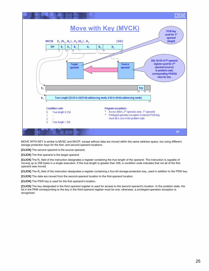
Move with Key (MVCK)
MVCK D1(R1,B2),D2(B2),R3 [SS]
Condition code:0 True length ≤ 2561 –2 –3 True length > 256
Program exceptions:• Access (fetch, 2nd operand; store, 1st operand)• Privileged-operation exception if selected PSW-key-
mask bit is zero in the problem state
Sourceoperand
‘D9’0 16 32
R1 R320
B1 D1 B2 D28 12 36 47
True Length (32-63 in 24/31-bit addressing mode; 0-63 in 64-bit addressing mode)R10 63
R30 56 60 63
Key
Bits 56-59 of 3rd-operand register used for 2nd
operand (source);in problem state,
corresponding PKM bit must be one.
Targetoperand
PSW key used for 1st
operand (target)
MOVE WITH KEY is similar to MVSC and MVCP, except without data are moved within the same address space, but using different storage-protection keys for the first- and second-operand locations.
[CLICK] The second operand is the source operand.
[CLICK] The first operand is the target operand.
[CLICK] The R1 field of the instruction designates a register containing the true length of the operand. The instruction is capable of moving up to 256 bytes in a single execution. If the true length is greater than 256, a condition code indicates that not all of the first operand was moved.
[CLICK] The R3 field of the instruction designates a register containing a four-bit storage-protection key, used in addition to the PSW key.
[CLICK] The data are moved from the second-operand location to the first-operand location.
[CLICK] The PSW key is used for the first operand’s location.
[CLICK] The key designated in the third operand register is used for access to the second operand’s location. In the problem state, the bit in the PKM corresponding to the key in the third-operand register must be one; otherwise, a privileged-operation exception is recognized.
26
26
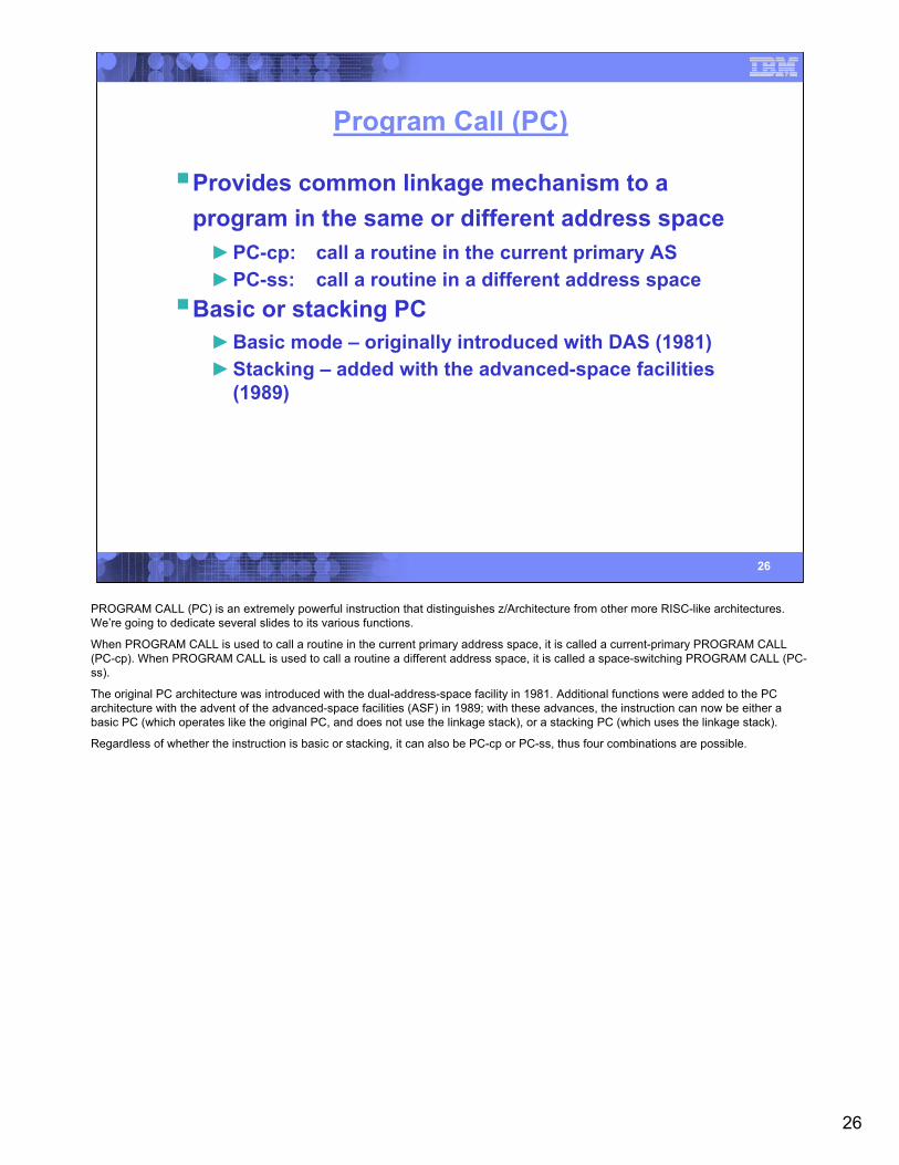
Program Call (PC)
Provides common linkage mechanism to a program in the same or different address space►PC-cp: call a routine in the current primary AS►PC-ss: call a routine in a different address space
Basic or stacking PC►Basic mode – originally introduced with DAS (1981)►Stacking – added with the advanced-space facilities
(1989)
PROGRAM CALL (PC) is an extremely powerful instruction that distinguishes z/Architecture from other more RISC-like architectures. We’re going to dedicate several slides to its various functions.
When PROGRAM CALL is used to call a routine in the current primary address space, it is called a current-primary PROGRAM CALL (PC-cp). When PROGRAM CALL is used to call a routine a different address space, it is called a space-switching PROGRAM CALL (PC-ss).
The original PC architecture was introduced with the dual-address-space facility in 1981. Additional functions were added to the PC architecture with the advent of the advanced-space facilities (ASF) in 1989; with these advances, the instruction can now be either a basic PC (which operates like the original PC, and does not use the linkage stack), or a stacking PC (which uses the linkage stack).
Regardless of whether the instruction is basic or stacking, it can also be PC-cp or PC-ss, thus four combinations are possible.

27
27
PC Number Translation
Second-operand address …
PC D2(B2) [S]
‘B228’ B2 D20 16 20 31
LX44 56
EX63
LSX51 56
EX63
0 LFX4544
LSX51 56
EX63
1 LFX24544
LFX132
LX
LFX
LX
… when ASN-and-LX-reuse facility not enabled:
… when ASN-and-LX-reuse facility enabled,and bit 44 of 2nd-operand address is zero:
… when ASN-and-LX-reuse facility enabled,and bit 44 of 2nd-operand address is one:
PC Number
Regardless of which form of PC is used, the instruction format is the same. The operand of the PC instruction is not used to access storage; rather, the rightmost bits of the operand address form what is called a PC number.
In the original PC, the PC number is a 24-bit value that is split into a 12-bit linkage index (LX) and an 8-bit entry index (EX). The ASN-and-LX-reuse facility (added with the z990) provides the option of having an extended 31-bit PC number which, curiously, has a bit in the middle indicating which of two formats are used. In the extended PC number, the linkage index (LX) is broken into a first and second part (LFX and LSX, respectively), and when bit 44 of the operand address is one, the LFX is a set of discontiguous bits with bit 44 in the middle!
If you’ve ever examined other parts of the architecture closely, you’ll notice that there are a lot of values that are chopped into smaller indices. A prime example is a virtual address which may be divided into up to three region indices, a segment index, page index, and byte index. The reason for the division is that each of these indices is used by the machine to find an entry in a table that resides in real or absolute storage. As it is extremely difficult for most operating systems to consolidate large blocks of real or absolute storage into a contiguous block that can be indexed by a large value, these tables are kept relatively small, and a higher-level index is used to locate an entry that designates a subordinate table used by a lower-level index.
28
28
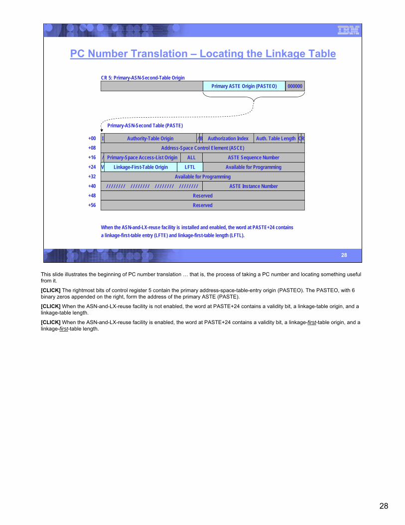
PC Number Translation – Locating the Linkage Table
000000Primary ASTE Origin (PASTEO)CR 5: Primary-ASN-Second-Table Origin
I Authority-Table Origin / B Authorization Index Auth. Table Length CR
Address-Space Control Element (ASCE)
Primary-Space Access-List Origin/ ALL ASTE Sequence Number
Available for Programming
Available for Programming
/ / / / / / / / / / / / / / / / / / / / / / / / / / / / / / / / ASTE Instance Number
Reserved
Reserved
+00
+08
+16
+24
+32
+40
+48
+56
V Linkage-Table Origin LTL
Primary-ASN-Second Table (PASTE)
V Linkage-Table Origin LTLV Linkage-First-Table Origin LFTL
When the ASN-and-LX-reuse facility is installed and enabled, the word at PASTE+24 containsa linkage-first-table entry (LFTE) and linkage-first-table length (LFTL).
This slide illustrates the beginning of PC number translation … that is, the process of taking a PC number and locating something useful from it.
[CLICK] The rightmost bits of control register 5 contain the primary address-space-table-entry origin (PASTEO). The PASTEO, with 6 binary zeros appended on the right, form the address of the primary ASTE (PASTE).
[CLICK] When the ASN-and-LX-reuse facility is not enabled, the word at PASTE+24 contains a validity bit, a linkage-table origin, and a linkage-table length.
[CLICK] When the ASN-and-LX-reuse facility is enabled, the word at PASTE+24 contains a validity bit, a linkage-first-table origin, and a linkage-first-table length.
29
29
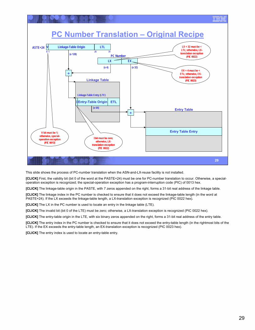
PC Number Translation – Original RecipeV Linkage-Table Origin LTLASTE+24
LX EX
(x 128)
Linkage Table
Entry Table
Entry Table Entry
+
+(x 64)
I Entry-Table Origin ETL
Linkage-Table Entry (LTE)
0 1 3125
(x 32)(x 4)
PC Number
V bit must be 1; otherwise, special-
operation exception(PIC 0013)
LX ÷ 32 must be < LTL; otherwise, LX-
translation exception (PIC 0022)
EX ÷ 4 must be < ETL; otherwise, EX-
translation exception (PIC 0023)
I bit must be zero; otherwise, LX-
translation exception (PIC 0022)
This slide shows the process of PC-number translation when the ASN-and-LX-reuse facility is not installed.
[CLICK] First, the validity bit (bit 0 of the word at the PASTE+24) must be one for PC-number translation to occur. Otherwise, a special-operation exception is recognized; the special-operation exception has a program-interruption code (PIC) of 0013 hex.
[CLICK] The linkage-table origin in the PASTE, with 7 zeros appended on the right, forms a 31-bit real address of the linkage table.
[CLICK] The linkage index in the PC number is checked to ensure that it does not exceed the linkage-table length (in the word at PASTE+24). If the LX exceeds the linkage-table length, a LX-translation exception is recognized (PIC 0022 hex).
[CLICK] The LX in the PC number is used to locate an entry in the linkage table (LTE).
[CLICK] The invalid bit (bit 0 of the LTE) must be zero; otherwise, a LX-translation exception is recognized (PIC 0022 hex).
[CLICK] The entry-table origin in the LTE, with six binary zeros appended on the right, forms a 31-bit real address of the entry table.
[CLICK] The entry index in the PC number is checked to ensure that it does not exceed the entry-table length (in the rightmost bits of the LTE). If the EX exceeds the entry-table length, an EX-translation exception is recognized (PIC 0023 hex).
[CLICK] The entry index is used to locate an entry-table entry.

30
30
PC Number Translation – Extra Crispy*V Linkage-First-Table Origin LFTLASTE+24
(x 256)
+
0 1 3124
(x 4)
LFX EXLSX
Linkage 2nd Table
I ETO ETLLinkage-2nd-Table Entry (LSTE)
LSTESN
Entry Table
Entry-Table Entry (ETE)
Linkage 1st Table
I LSTO ////////
Linkage-1st-Table Entry (LFTE)
(x 32)
+(x 64)
+
(x 8)
(x 256)
PC Number
* When the ASN-and-LX-reuse facility is installed and enabled.
V bit must be 1; otherwise, special-
operation exception(PIC 0013)
LFX ÷ 64 must be < LFTL; otherwise, LFX-translation
exception (PIC 0026)
I bit must be zero; otherwise, LFX-
translation exception (PIC 0026) I bit must be zero;
otherwise, LSX-translation exception
(PIC 0027)
EX ÷ 4 must be < ETL; otherwise, EX-
translation exception (PIC 0023)
This slide illustrates the process of PC-number translation when the ASN-and-LX-reuse facility is enabled. The process is similar to that when ALRF is not installed, but with the differences noted below:
[CLICK] As with non-ALRF PC, we fist check the validity bit (bit 0 of the word at the PASTE+24) which must be one for PC-number translation to occur. Otherwise, a special-operation exception is recognized; the special-operation exception has a program-interruption code (PIC) of 0013 hex.
[CLICK] The linkage-first index (LFX) in the PC number is checked to ensure that it does not exceed the linkage-table length (in the word at PASTE+24). If the LFX exceeds the linkage-table length, a LX-first-translation exception is recognized (PIC 0026 hex).
[CLICK] The LFX in the PC number is added to the linkage-first-table origin to locate an entry in the linkage-first table (LFTE).
[CLICK] The invalid bit (bit 0 of the LFTE) must be zero; otherwise, a LFX-translation exception is recognized (PIC 0026 hex).
[CLICK] The linkage-second index (LSX) in the PC number is added to the linkage-second-table origin (LSTO, found in the LFTE) to locate an entry in the linkage-second table (LSTE). Note that unlike the LFX, which is checked for a maximum length, there is no checking of a maximum LSX value.
[CLICK] The invalid bit (bit 0 of the LSTE) must be zero; otherwise, a LSX-translation exception is recognized (PIC 0027 hex).
[CLICK] The entry index in the PC number is checked to ensure that it does not exceed the entry-table length (in the rightmost bits of the LSTE). If the EX exceeds the entry-table length, an EX-translation exception is recognized (PIC 0023 hex).
[CLICK] The entry-table origin in the LSTE, with six binary zeros appended on the right, forms a 31-bit real address of the entry table. The entry index (EX) in the PC number, multiplied by 32, is used to locate the entry-table entry (ETE) in the entry table.
Regardless of whether ALRF is enabled, the results of the original-recipe or extra-crispy PC-number translation is an entry-table entry, described in the following slide.
31
31
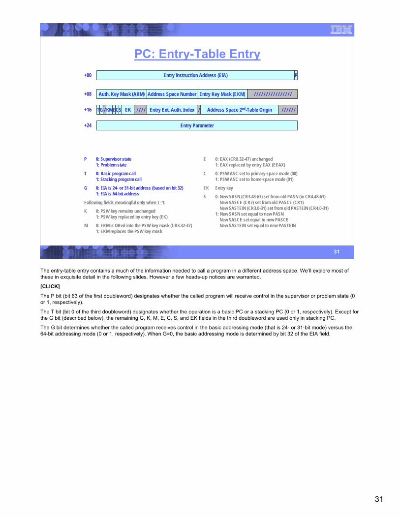
PC: Entry-Table EntryEntry Instruction Address (EIA) P
Entry Parameter
+00
+08
+16
+24
Auth. Key Mask (AKM) Address Space Number Entry Key Mask (EKM) / / / / / / / / / / / / / / / /
/Entry Ext. Auth. Index Address Space 2nd-Table OriginTG / / / / / // KMECS EK / / / /
E 0: EAX (CR8.32-47) unchanged1: EAX replaced by entry EAX (EEAX)
C 0: PSW ASC set to primary-space mode (00)1: PSW ASC set to home-space mode (01)
EK Entry key
S 0: New SASN (CR3.48-63) set from old PASN (in CR4.48-63)New SASCE (CR7) set from old PASCE (CR1)New SASTEIN (CR3.0-31) set from old PASTEIN (CR4.0-31)
1: New SASN set equal to new PASNNew SASCE set equal to new PASCENew SASTEIN set equal to new PASTEIN
P 0: Supervisor state1: Problem state
T 0: Basic program call1: Stacking program call
G 0: EIA is 24- or 31-bit address (based on bit 32) 1: EIA is 64-bit address
Following fields meaningful only when T=1:
K 0: PSW key remains unchanged1: PSW key replaced by entry key (EK)
M 0: EKM is ORed into the PSW key mask (CR3.32-47)1: EKM replaces the PSW key mask
The entry-table entry contains a much of the information needed to call a program in a different address space. We’ll explore most of these in exquisite detail in the following slides. However a few heads-up notices are warranted.
[CLICK]
The P bit (bit 63 of the first doubleword) designates whether the called program will receive control in the supervisor or problem state (0 or 1, respectively).
The T bit (bit 0 of the third doubleword) designates whether the operation is a basic PC or a stacking PC (0 or 1, respectively). Except for the G bit (described below), the remaining G, K, M, E, C, S, and EK fields in the third doubleword are used only in stacking PC.
The G bit determines whether the called program receives control in the basic addressing mode (that is 24- or 31-bit mode) versus the 64-bit addressing mode (0 or 1, respectively). When G=0, the basic addressing mode is determined by bit 32 of the EIA field.
32
32
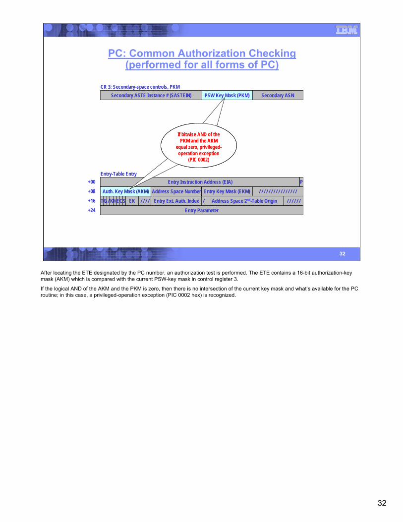
PC: Common Authorization Checking(performed for all forms of PC)
Entry Instruction Address (EIA) P
Entry Parameter
+00
+08
+16
+24
Auth. Key Mask (AKM) Address Space Number Entry Key Mask (EKM) / / / / / / / / / / / / / / / /
/Entry Ext. Auth. Index Address Space 2nd-Table OriginTG / / / / / // KMECS EK / / / /
Entry-Table Entry
CR 3: Secondary-space controls, PKMSecondary ASTE Instance # (SASTEIN) PSW Key Mask (PKM) Secondary ASN
If bitwise AND of the PKM and the AKM
equal zero, privileged-operation exception
(PIC 0002)
After locating the ETE designated by the PC number, an authorization test is performed. The ETE contains a 16-bit authorization-key mask (AKM) which is compared with the current PSW-key mask in control register 3.
If the logical AND of the AKM and the PKM is zero, then there is no intersection of the current key mask and what’s available for the PC routine; in this case, a privileged-operation exception (PIC 0002 hex) is recognized.
33
33
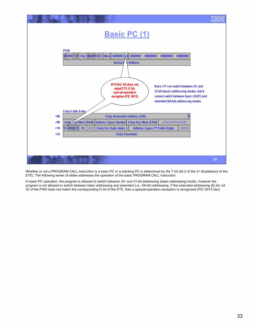
Basic PC (1)
Entry Instruction Address (EIA) P
Entry Parameter
+00
+08
+16
+24
Auth. Key Mask (AKM) Address Space Number Entry Key Mask (EKM) / / / / / / / / / / / / / / / /
/Entry Ext. Auth. Index Address Space 2nd-Table OriginTG / / / / / // KMECS EK / / / /
Entry-Table Entry
PSW:0R 000 T I E Key 0MWPAS MaskCC 0000000 EA 0000000 00000000 00000000 00000000
Instruction Address
If PSW.E bit does not equal ETE.G bit,
special-operation exception (PIC 0013)
Basic CP can switch between 24- and31-bit (basic) addressing modes, but itcannot switch between basic (24/31) andextended (64-bit) addressing modes.
Whether or not a PROGRAM CALL instruction is a basic PC or a stacking PC is determined by the T bit (bit 0 of the 3rd doubleword of the ETE). The following series of slides addresses the operation of the basic PROGRAM CALL instruction.
In basic PC operation, the program is allowed to switch between 24- and 31-bit addressing (basic addressing mode), however the program is not allowed to switch between basic addressing and extended (i.e., 64-bit) addressing. If the extended-addressing (E) bit, bit 32 of the PSW does not match the corresponding G bit of the ETE, then a special-operation exception is recognized (PIC 0013 hex).
34
34
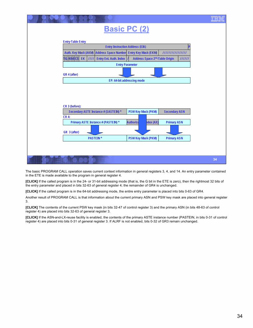
Basic PC (2)
CR 3 (before):Secondary ASTE Instance # (SASTEIN) * PSW Key Mask (PKM) Secondary ASN
CR 4:Primary ASTE Instance # (PASTEIN) * Authorization Index (AX) Primary ASN
EP: 24- or 31-bit addressing mode/ / / / / / / / / / / / / / / / / / / / / / / / / / / / / / / /
GR 4 (after)
EP: 64-bit addressing mode
Entry-Table EntryEntry Instruction Address (EIA) P
Auth. Key Mask (AKM) Address Space Number Entry Key Mask (EKM) / / / / / / / / / / / / / / / /
/Entry Ext. Auth. Index Address Space 2nd-Table OriginTG / / / / / // KMECS EK / / / /
Entry Parameter/ / / / / / / / / / / / / / / / / / / / / / / / / / / / / / / /Entry Parameter
GR 3 (after)
Primary ASNPSW Key Mask (PKM)PASTEIN *
The basic PROGRAM CALL operation saves current context information in general registers 3, 4, and 14. An entry parameter contained in the ETE is made available to the program in general register 4.
[CLICK] If the called program is in the 24- or 31-bit addressing mode (that is, the G bit in the ETE is zero), then the rightmost 32 bits of the entry parameter and placed in bits 32-63 of general register 4; the remainder of GR4 is unchanged.
[CLICK] If the called program is in the 64-bit addressing mode, the entire entry parameter is placed into bits 0-63 of GR4.
Another result of PROGRAM CALL is that information about the current primary ASN and PSW key mask are placed into general register 3.
[CLICK] The contents of the current PSW key mask (in bits 32-47 of control register 3) and the primary ASN (in bits 48-63 of control register 4) are placed into bits 32-63 of general register 3.
[CLICK] If the ASN-and-LX-reuse facility is enabled, the contents of the primary ASTE instance number (PASTEIN, in bits 0-31 of control register 4) are placed into bits 0-31 of general register 3. If ALRF is not enabled, bits 0-32 of GR3 remain unchanged.

35
35
Basic PC (3)PSW (before):0R 000 T I E Key 0MWPAS MaskCC 0000000 EA 0000000 00000000 00000000 00000000
00000000 00000000 00000000 00000000 0 Next Sequential Instruction AddressNext Sequential Instruction Address
GR 14 (after)
/ / / / / / / / / / / / / / / / / / / / / / / / / / / / / / / / Return instruction address PAReturn instruction address
PSW (after):0R 000 T I E Key 0MWPAS MaskCC 0000000 EA 0000000 00000000 00000000 00000000
00000000 00000000 00000000 00000000 0 Next Sequential Instruction AddressNext Sequential Instruction Address
Entry-Table Entry
Auth. Key Mask (AKM) Address Space Number Entry Key Mask (EKM) / / / / / / / / / / / / / / / /
/Entry Ext. Auth. Index Address Space 2nd-Table OriginTG / / / / / // KMECS EK / / / /
Entry Parameter
PNext Sequential Instruction AddressA00000000 00000000 00000000 00000000Entry Instruction Address (EIA)
The PSW instruction address contains the address of the instruction following the PROGRAM CALL. The instruction address, basic-addressing-mode bit (when in the 24- or 31-bit addressing mode), and the problem-state bit of the PSW are preserved for use by the PROGRAM TRANSFER instruction, to allow returning to the caller.
[CLICK] These data are placed into general register 14.
[CLICK] In the 24- or 31-bit addressing mode, bits 33-62 of the PSW instruction-address field (bits 97-126 of the PSW) are placed in bits 33-62 of general register 14. The basic-addressing mode (bit 32 of the PSW) is placed in the corresponding bit of GR14, and the problem-state bit (bit 15 of the PSW) is placed in bit 63 of GR14.
[CLICK] In the 64-bit addressing mode, the bits 0-62 of the PSW are placed in the corresponding bits of general register 14, and the PSW problem-state bit is placed in bit 63 of GR14.
[CLICK] Next, the entry-instruction address (EIA) in the ETE is placed in the PSW that will receive control when the instruction completes.
[CLICK] In the 24- or 31-bit addressing mode, bits 33-62 of the EIA, with a zero on the right, are placed into bits 97-127 of the PSW instruction address (actually, PSW bits 97-126). Bit 32 of the EIA is placed in bit 32 of the PSW (the basic-addressing mode bit that selects between 24- and 31-bit addressing). Finally, bit 63 of the EIA becomes the new PSW problem-state bit (PSW bit 15).
[CLICK] In the 64-bit mode, bits 0-62 of the EIA, with a zero on the right, are placed into the PSW instruction address (PSW bits 64-127). Bit 63 of the EIA becomes the new PSW problem-state bit (PSW bit 15).
36
36
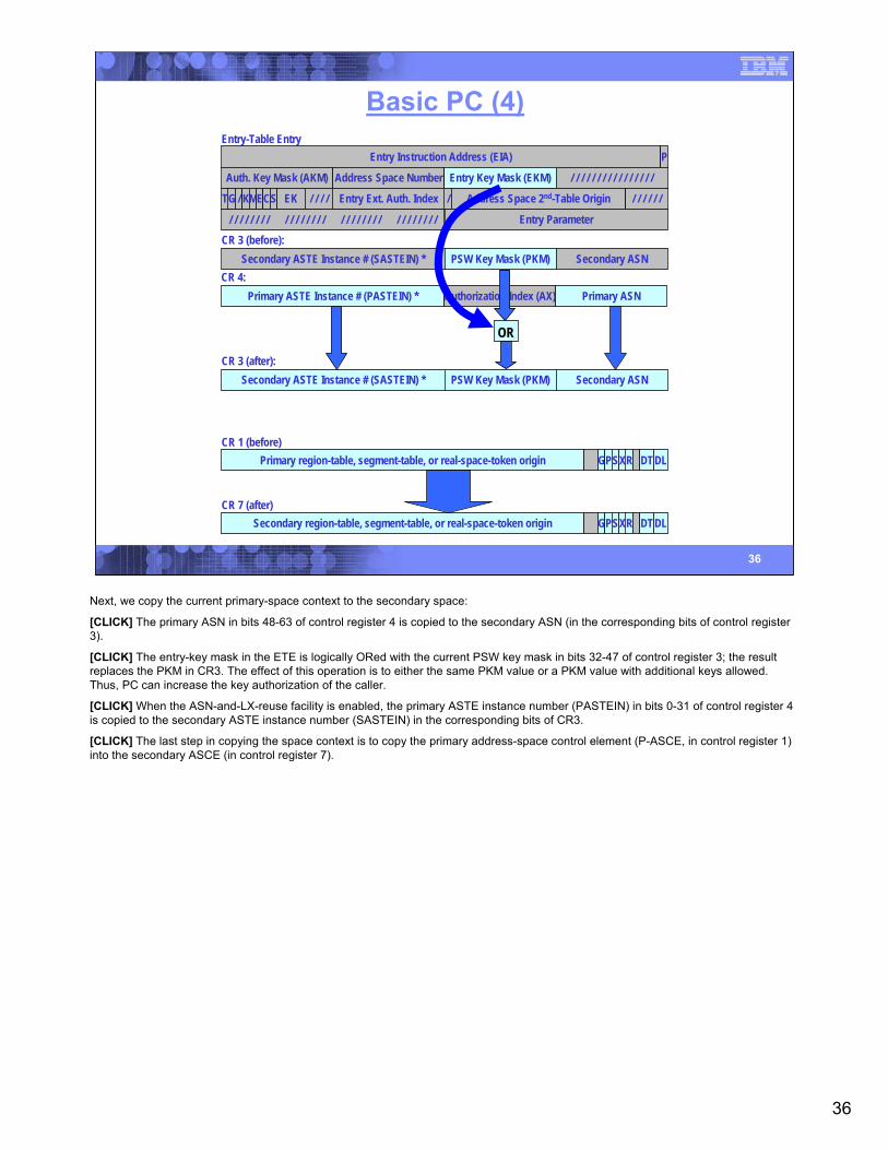
Basic PC (4)
CR 3 (before):Secondary ASTE Instance # (SASTEIN) * PSW Key Mask (PKM) Secondary ASN
CR 4:Primary ASTE Instance # (PASTEIN) * Authorization Index (AX) Primary ASN
Entry-Table EntryEntry Instruction Address (EIA) P
Auth. Key Mask (AKM) Address Space Number Entry Key Mask (EKM) / / / / / / / / / / / / / / / /
/Entry Ext. Auth. Index Address Space 2nd-Table OriginTG / / / / / // KMECS EK / / / /
Entry Parameter/ / / / / / / / / / / / / / / / / / / / / / / / / / / / / / / /
CR 3 (after):Secondary ASTE Instance # (SASTEIN) * PSW Key Mask (PKM) Secondary ASN
OR
Primary region-table, segment-table, or real-space-token origin GPSXR DTDLCR 1 (before)
Secondary region-table, segment-table, or real-space-token origin GPSXR DTDLCR 7 (after)
Next, we copy the current primary-space context to the secondary space:
[CLICK] The primary ASN in bits 48-63 of control register 4 is copied to the secondary ASN (in the corresponding bits of control register 3).
[CLICK] The entry-key mask in the ETE is logically ORed with the current PSW key mask in bits 32-47 of control register 3; the result replaces the PKM in CR3. The effect of this operation is to either the same PKM value or a PKM value with additional keys allowed. Thus, PC can increase the key authorization of the caller.
[CLICK] When the ASN-and-LX-reuse facility is enabled, the primary ASTE instance number (PASTEIN) in bits 0-31 of control register 4 is copied to the secondary ASTE instance number (SASTEIN) in the corresponding bits of CR3.
[CLICK] The last step in copying the space context is to copy the primary address-space control element (P-ASCE, in control register 1) into the secondary ASCE (in control register 7).
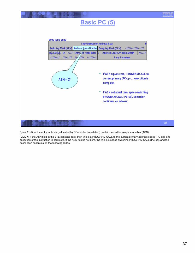
37
37
Basic PC (5)
Entry-Table EntryEntry Instruction Address (EIA) P
Auth. Key Mask (AKM) Address Space Number Entry Key Mask (EKM) / / / / / / / / / / / / / / / /
/Entry Ext. Auth. Index Address Space 2nd-Table OriginTG / / / / / // KMECS EK / / / /
Entry Parameter/ / / / / / / / / / / / / / / / / / / / / / / / / / / / / / / /
ASN = 0?• If ASN equals zero, PROGRAM CALL to
current primary (PC-cp) … execution is complete.
• If ASN not equal zero, space-switching PROGRAM CALL (PC-ss). Execution continues as follows:
Bytes 11-12 of the entry table entry (located by PC-number translation) contains an address-space number (ASN).
[CLICK] If the ASN field in the ETE contains zero, then this is a PROGRAM CALL to the current primary address space (PC-cp), and execution of the instruction is complete. If the ASN field is not zero, the this is a space-switching PROGRAM CALL (PC-ss), and the description continues on the following slides.
38
38
Space-Switching PC (1)Entry-Table Entry
Entry Instruction Address (EIA) P
Auth. Key Mask (AKM) Address Space Number Entry Key Mask (EKM) / / / / / / / / / / / / / / / /
/Entry Ext. Auth. Index Address Space 2nd-Table OriginTG 000000/ KMECS EK / / / /
Entry Parameter/ / / / / / / / / / / / / / / / / / / / / / / / / / / / / / / /
I Authority-Table Origin / B Authorization Index Auth. Table Length CR
Address-Space Control Element (ASCE)
Primary-Space Access-List Origin/ ALL ASTE Sequence Number
Available for Programming
/ / / / / / / / / / / / / / / / / / / / / / / / / / / / / / / / ASTE Instance Number
Reserved
Reserved
Available for ProgrammingV Linkage-Table Origin LTL
ASN-Second Table (ASTE)
Primary region-table, segment-table, or real-space-token origin GPSXR DTDLCR 1 (after):
If I bit is one, ASX-translation
exception(PIC 0021)
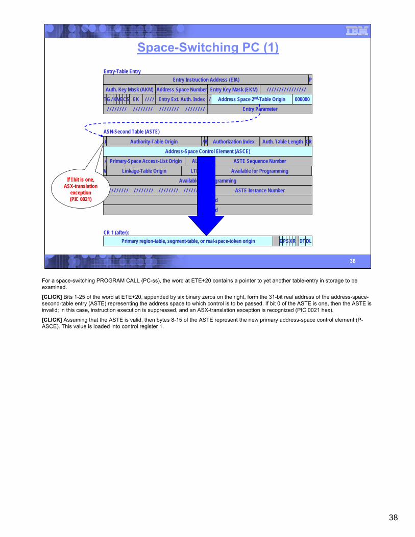
For a space-switching PROGRAM CALL (PC-ss), the word at ETE+20 contains a pointer to yet another table-entry in storage to be examined.
[CLICK] Bits 1-25 of the word at ETE+20, appended by six binary zeros on the right, form the 31-bit real address of the address-space-second-table entry (ASTE) representing the address space to which control is to be passed. If bit 0 of the ASTE is one, then the ASTE is invalid; in this case, instruction execution is suppressed, and an ASX-translation exception is recognized (PIC 0021 hex).
[CLICK] Assuming that the ASTE is valid, then bytes 8-15 of the ASTE represent the new primary address-space control element (P-ASCE). This value is loaded into control register 1.
39
39
Space-Switching PC (2)Entry-Table Entry
Entry Instruction Address (EIA) P
Auth. Key Mask (AKM) Address Space Number Entry Key Mask (EKM) / / / / / / / / / / / / / / / /
/Entry Ext. Auth. Index Address Space 2nd-Table OriginTG 000000/ KMECS EK / / / /
Entry Parameter/ / / / / / / / / / / / / / / / / / / / / / / / / / / / / / / /
I Authority-Table Origin / B Authorization Index Auth. Table Length CR
Address-Space Control Element (ASCE)
Primary-Space Access-List Origin/ ALL ASTE Sequence Number
Available for Programming
/ / / / / / / / / / / / / / / / / / / / / / / / / / / / / / / / ASTE Instance Number
Reserved
Reserved
Available for ProgrammingV Linkage-Table Origin LTL
ASN-Second Table (ASTE)
CR 4 (after):Primary ASTE Instance # (PASTEIN) * Authorization Index (AX) Primary ASN
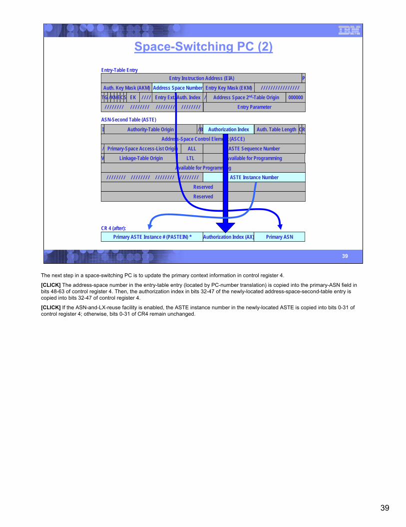
The next step in a space-switching PC is to update the primary context information in control register 4.
[CLICK] The address-space number in the entry-table entry (located by PC-number translation) is copied into the primary-ASN field in bits 48-63 of control register 4. Then, the authorization index in bits 32-47 of the newly-located address-space-second-table entry is copied into bits 32-47 of control register 4.
[CLICK] If the ASN-and-LX-reuse facility is enabled, the ASTE instance number in the newly-located ASTE is copied into bits 0-31 of control register 4; otherwise, bits 0-31 of CR4 remain unchanged.
40
40
Space-Switching PC (3)
Entry-Table EntryEntry Instruction Address (EIA) P
Auth. Key Mask (AKM) Address Space Number Entry Key Mask (EKM) / / / / / / / / / / / / / / / /
/Entry Ext. Auth. Index Address Space 2nd-Table OriginTG 000000/ KMECS EK / / / /
Entry Parameter/ / / / / / / / / / / / / / / / / / / / / / / / / / / / / / / /
CR 5 (after)Primary ASTE Origin (PASTEO) 000000
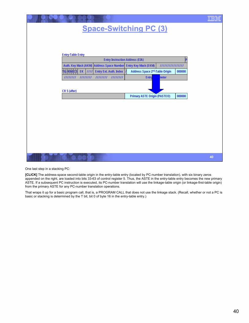
One last step in a stacking PC:
[CLICK] The address-space second-table origin in the entry-table entry (located by PC-number translation), with six binary zeros appended on the right, are loaded into bits 33-63 of control register 5. Thus, the ASTE in the entry-table entry becomes the new primary ASTE. If a subsequent PC instruction is executed, its PC-number translation will use the linkage-table origin (or linkage-first-table origin) from the primary ASTE for any PC-number translation operations.
That wraps it up for a basic program call, that is, a PROGRAM CALL that does not use the linkage stack. (Recall, whether or not a PC is basic or stacking is determined by the T bit, bit 0 of byte 16 in the entry-table entry.)
41
41
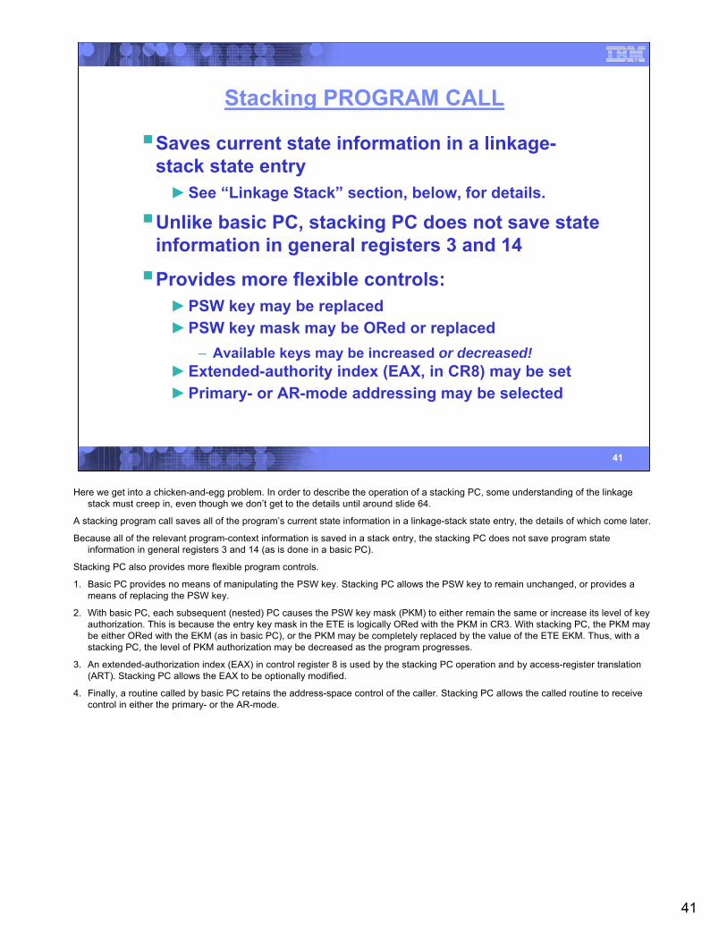
Stacking PROGRAM CALL
Saves current state information in a linkage-stack state entry►See “Linkage Stack” section, below, for details.
Unlike basic PC, stacking PC does not save state information in general registers 3 and 14
Provides more flexible controls:►PSW key may be replaced►PSW key mask may be ORed or replaced
– Available keys may be increased or decreased!►Extended-authority index (EAX, in CR8) may be set►Primary- or AR-mode addressing may be selected
Here we get into a chicken-and-egg problem. In order to describe the operation of a stacking PC, some understanding of the linkage stack must creep in, even though we don’t get to the details until around slide 64.
A stacking program call saves all of the program’s current state information in a linkage-stack state entry, the details of which come later.
Because all of the relevant program-context information is saved in a stack entry, the stacking PC does not save program state information in general registers 3 and 14 (as is done in a basic PC).
Stacking PC also provides more flexible program controls.
1. Basic PC provides no means of manipulating the PSW key. Stacking PC allows the PSW key to remain unchanged, or provides a means of replacing the PSW key.
2. With basic PC, each subsequent (nested) PC causes the PSW key mask (PKM) to either remain the same or increase its level of key authorization. This is because the entry key mask in the ETE is logically ORed with the PKM in CR3. With stacking PC, the PKM may be either ORed with the EKM (as in basic PC), or the PKM may be completely replaced by the value of the ETE EKM. Thus, with a stacking PC, the level of PKM authorization may be decreased as the program progresses.
3. An extended-authorization index (EAX) in control register 8 is used by the stacking PC operation and by access-register translation (ART). Stacking PC allows the EAX to be optionally modified.
4. Finally, a routine called by basic PC retains the address-space control of the caller. Stacking PC allows the called routine to receive control in either the primary- or the AR-mode.
42
42
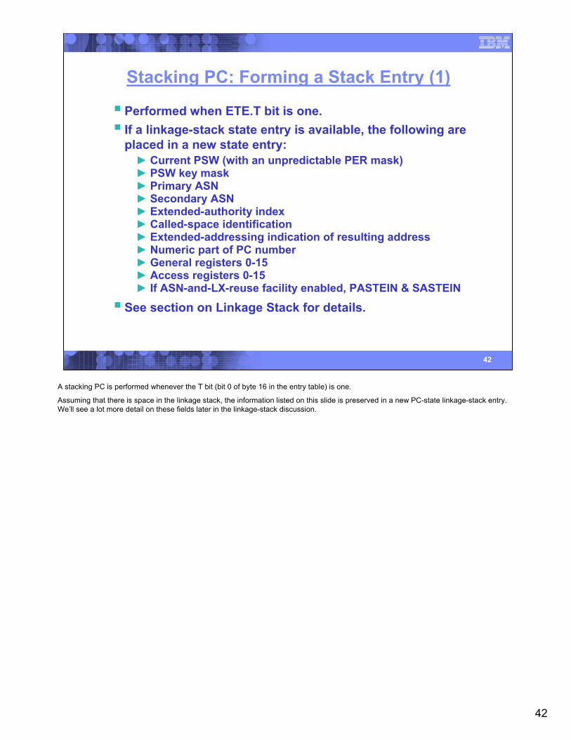
Stacking PC: Forming a Stack Entry (1)
Performed when ETE.T bit is one.If a linkage-stack state entry is available, the following are placed in a new state entry:► Current PSW (with an unpredictable PER mask)► PSW key mask► Primary ASN► Secondary ASN► Extended-authority index► Called-space identification► Extended-addressing indication of resulting address► Numeric part of PC number► General registers 0-15► Access registers 0-15► If ASN-and-LX-reuse facility enabled, PASTEIN & SASTEIN
See section on Linkage Stack for details.
A stacking PC is performed whenever the T bit (bit 0 of byte 16 in the entry table) is one.
Assuming that there is space in the linkage stack, the information listed on this slide is preserved in a new PC-state linkage-stack entry. We’ll see a lot more detail on these fields later in the linkage-stack discussion.
43
43
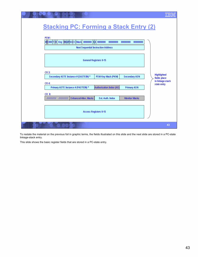
Stacking PC: Forming a Stack Entry (2)
CR 3:Secondary ASTE Instance # (SASTEIN) * PSW Key Mask (PKM) Secondary ASN
CR 4:Primary ASTE Instance # (PASTEIN) * Authorization Index (AX) Primary ASN
PSW :0R 000 T I E Key 0MWPAS MaskCC 0000000 EA 0000000 00000000 00000000 00000000
Next Sequential Instruction Address
CR 8:Enhanced-Mon. Masks/ / / / / / / / / / / / / / / / Ext. Auth. Index Monitor Masks
General Registers 0-15
Access Registers 0-15
Highlightedfields placein linkage-stackstate entry
To restate the material on the previous foil in graphic terms, the fields illustrated on this slide and the next slide are stored in a PC-state linkage-stack entry.
This slide shows the basic register fields that are stored in a PC-state entry.
44
44
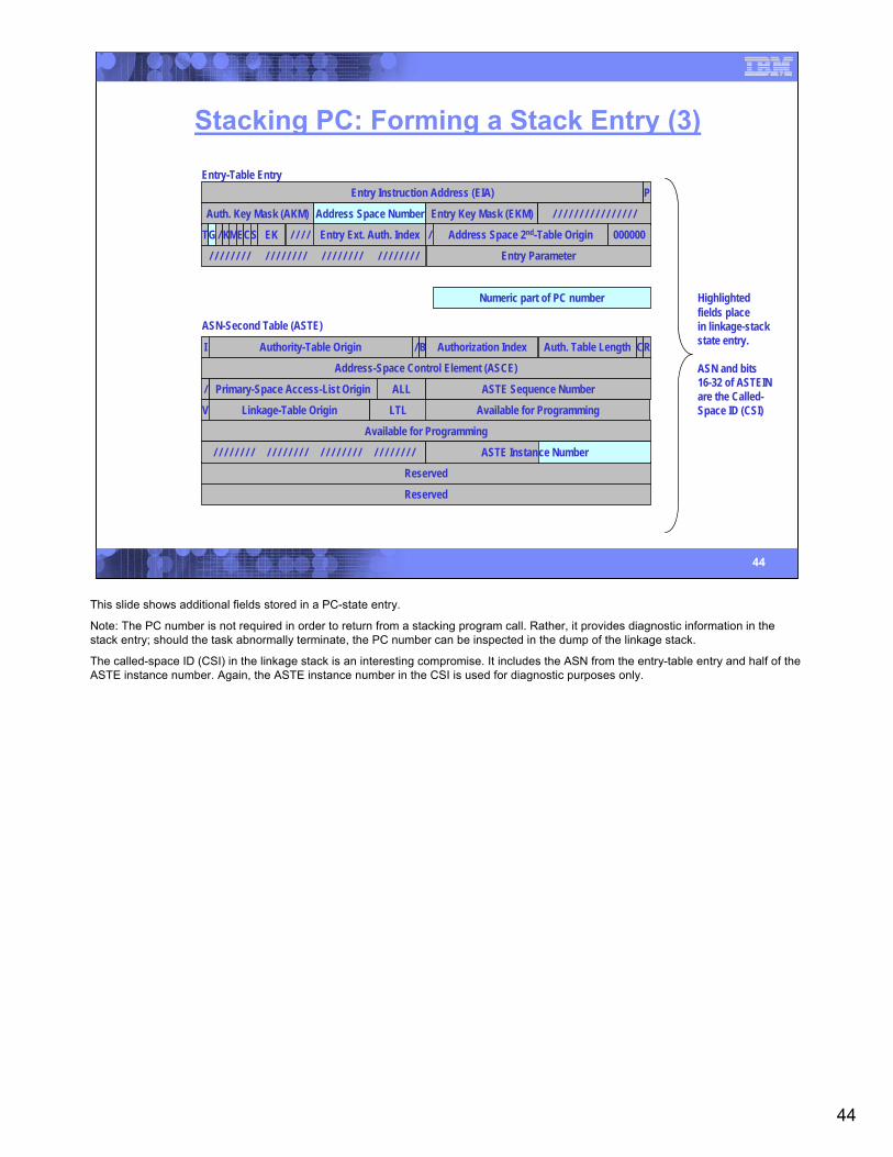
Stacking PC: Forming a Stack Entry (3)
Entry-Table EntryEntry Instruction Address (EIA) P
Auth. Key Mask (AKM) Address Space Number Entry Key Mask (EKM) / / / / / / / / / / / / / / / /
/Entry Ext. Auth. Index Address Space 2nd-Table OriginTG 000000/ KMECS EK / / / /
Entry Parameter/ / / / / / / / / / / / / / / / / / / / / / / / / / / / / / / /
Highlightedfields placein linkage-stackstate entry.
ASN and bits16-32 of ASTEINare the Called-Space ID (CSI)
Numeric part of PC number
ASN-Second Table (ASTE)
I Authority-Table Origin / B Authorization Index Auth. Table Length CR
Address-Space Control Element (ASCE)
Primary-Space Access-List Origin/ ALL ASTE Sequence Number
Available for Programming
Reserved
Reserved
Available for ProgrammingV Linkage-Table Origin LTL
/ / / / / / / / / / / / / / / / / / / / / / / / / / / / / / / / ASTE Instance Number
This slide shows additional fields stored in a PC-state entry.
Note: The PC number is not required in order to return from a stacking program call. Rather, it provides diagnostic information in the stack entry; should the task abnormally terminate, the PC number can be inspected in the dump of the linkage stack.
The called-space ID (CSI) in the linkage stack is an interesting compromise. It includes the ASN from the entry-table entry and half of the ASTE instance number. Again, the ASTE instance number in the CSI is used for diagnostic purposes only.
45
45
Stacking PC: Updating the PSW
PSW (after):
0R 000 T I E Key 0MWPAS MaskCC 0000000 EA 0000000 00000000 00000000 00000000
00000000 00000000 00000000 00000000 0 Next Sequential Instruction AddressNext Sequential Instruction Address
Entry-Table Entry
Auth. Key Mask (AKM) Address Space Number Entry Key Mask (EKM) / / / / / / / / / / / / / / / /
/Entry Ext. Auth. Index Address Space 2nd-Table OriginTG / / / / / // KMECS EK / / / /
Entry Parameter
PNext Sequential Instruction AddressA00000000 00000000 00000000 00000000Entry Instruction Address (EIA)
If ETE.K is one, ETE.EK placed in
PSW key field
PSW.16 set to zero; PSW.17 set
from ETE.C bit
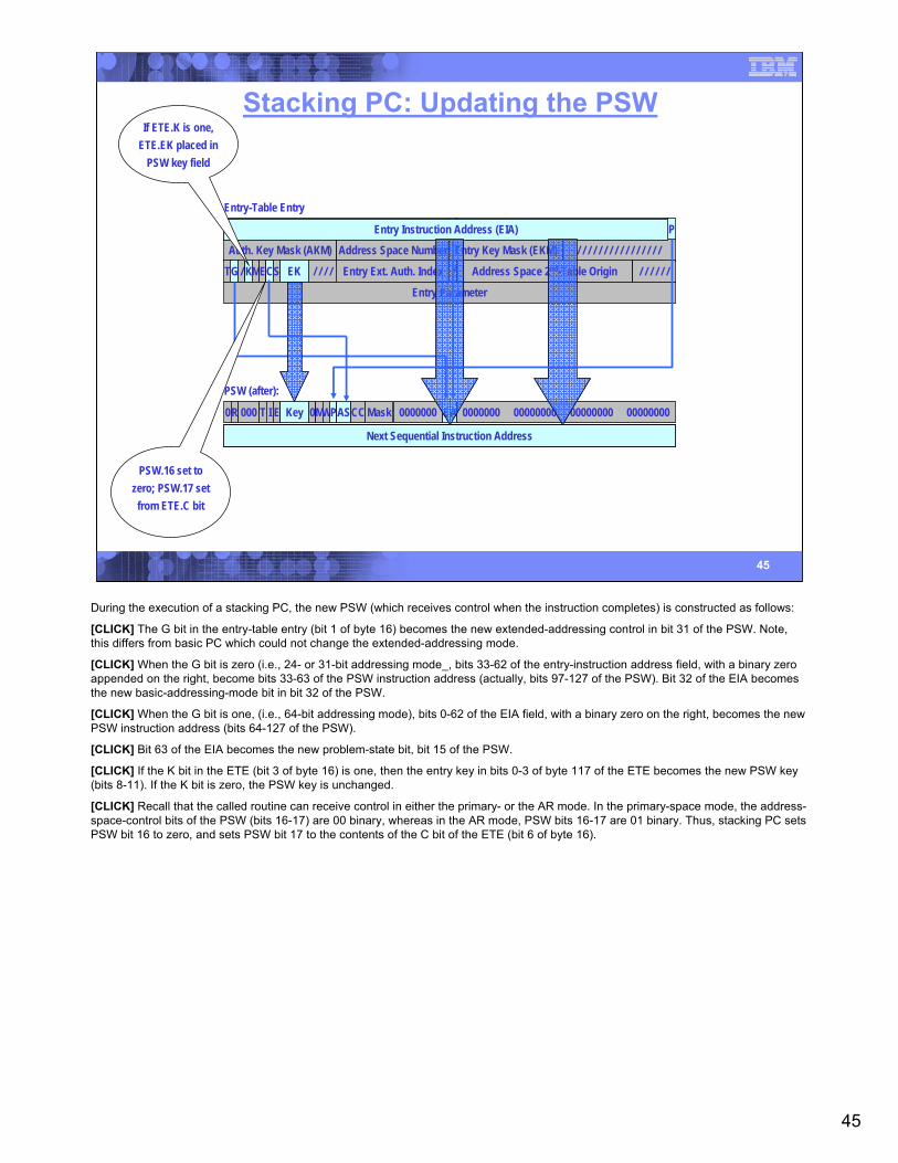
During the execution of a stacking PC, the new PSW (which receives control when the instruction completes) is constructed as follows:
[CLICK] The G bit in the entry-table entry (bit 1 of byte 16) becomes the new extended-addressing control in bit 31 of the PSW. Note, this differs from basic PC which could not change the extended-addressing mode.
[CLICK] When the G bit is zero (i.e., 24- or 31-bit addressing mode_, bits 33-62 of the entry-instruction address field, with a binary zero appended on the right, become bits 33-63 of the PSW instruction address (actually, bits 97-127 of the PSW). Bit 32 of the EIA becomes the new basic-addressing-mode bit in bit 32 of the PSW.
[CLICK] When the G bit is one, (i.e., 64-bit addressing mode), bits 0-62 of the EIA field, with a binary zero on the right, becomes the new PSW instruction address (bits 64-127 of the PSW).
[CLICK] Bit 63 of the EIA becomes the new problem-state bit, bit 15 of the PSW.
[CLICK] If the K bit in the ETE (bit 3 of byte 16) is one, then the entry key in bits 0-3 of byte 117 of the ETE becomes the new PSW key (bits 8-11). If the K bit is zero, the PSW key is unchanged.
[CLICK] Recall that the called routine can receive control in either the primary- or the AR mode. In the primary-space mode, the address-space-control bits of the PSW (bits 16-17) are 00 binary, whereas in the AR mode, PSW bits 16-17 are 01 binary. Thus, stacking PC sets PSW bit 16 to zero, and sets PSW bit 17 to the contents of the C bit of the ETE (bit 6 of byte 16).
46
46
Stacking PC: Setting the PSW Key Mask
CR 3 (before):Secondary ASTE Instance # (SASTEIN) * PSW Key Mask (PKM) Secondary ASN
Entry-Table EntryEntry Instruction Address (EIA) P
Auth. Key Mask (AKM) Address Space Number / / / / / / / / / / / / / / / /
Entry Ext. Auth. Index Address Space 2nd-Table OriginTG / / / / / // KMECS EK / / / /
Entry Parameter/ / / / / / / / / / / / / / / / / / / / / / / / / / / / / / / /
CR 3 (after):Secondary ASTE Instance # (SASTEIN) * PSW Key Mask (PKM) Secondary ASN
/
OR
Entry Key Mask (EKM)
If ETE.E bit is zero, ETE.EKM is ORed with
current PSW key mask to form new PKM.
If ETE.E bit is one, entire ETE.EKM replaces PSW
key mask in CR3.
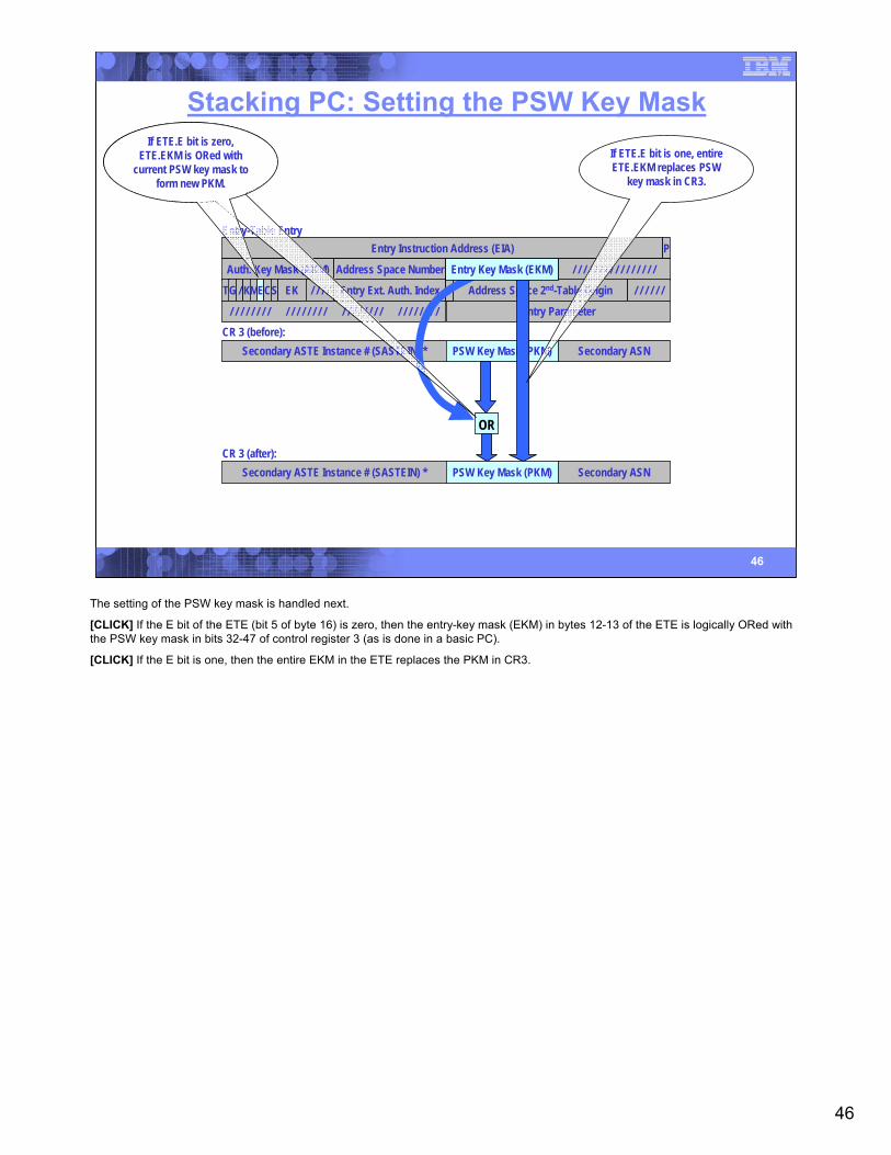
The setting of the PSW key mask is handled next.
[CLICK] If the E bit of the ETE (bit 5 of byte 16) is zero, then the entry-key mask (EKM) in bytes 12-13 of the ETE is logically ORed with the PSW key mask in bits 32-47 of control register 3 (as is done in a basic PC).
[CLICK] If the E bit is one, then the entire EKM in the ETE replaces the PKM in CR3.
47
47
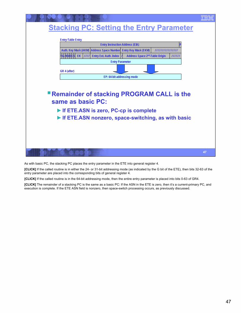
Stacking PC: Setting the Entry Parameter
EP: 24- or 31-bit addressing mode/ / / / / / / / / / / / / / / / / / / / / / / / / / / / / / / /
GR 4 (after)
EP: 64-bit addressing mode
Entry-Table EntryEntry Instruction Address (EIA) P
Auth. Key Mask (AKM) Address Space Number Entry Key Mask (EKM) / / / / / / / / / / / / / / / /
/Entry Ext. Auth. Index Address Space 2nd-Table OriginTG / / / / / // KMECS EK / / / /
Entry Parameter/ / / / / / / / / / / / / / / / / / / / / / / / / / / / / / / /Entry Parameter
Remainder of stacking PROGRAM CALL is the same as basic PC:► If ETE.ASN is zero, PC-cp is complete► If ETE.ASN nonzero, space-switching, as with basic
As with basic PC, the stacking PC places the entry parameter in the ETE into general register 4.
[CLICK] If the called routine is in either the 24- or 31-bit addressing mode (as indicated by the G bit of the ETE), then bits 32-63 of the entry parameter are placed into the corresponding bits of general register 4.
[CLICK] If the called routine is in the 64-bit addressing mode, then the entire entry parameter is placed into bits 0-63 of GR4.
[CLICK] The remainder of a stacking PC is the same as a basic PC: If the ASN in the ETE is zero, then it’s a current-primary PC, and execution is complete. If the ETE ASN field is nonzero, then space-switch processing occurs, as previously discussed.
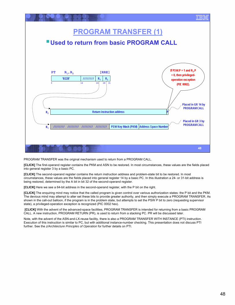
48
48
PROGRAM TRANSFER (1)
PT R1,R2 [RRE]
‘B228’ R2/ / / / / / / /0 16 24 31
R128
Address Space NumberPSW Key Mask (PKM)/ / / / / / / / / / / / / / / / / / / / / / / / / / / / / / / /R1
R2 Return instruction address PA/ / / / / / / / / / / / / / / / / / / / / / / / / / / / / / / /
Placed in GR 14 byPROGRAM CALL
Return instruction address
Placed in GR 3 byPROGRAM CALL
If PSW.P = 1 and R2.P = 0, then privileged-operation exception
(PIC 0002).
Used to return from basic PROGRAM CALL
PROGRAM TRANSFER was the original mechanism used to return from a PROGRAM CALL.
[CLICK] The first-operand register contains the PKM and ASN to be restored. In most circumstances, these values are the fields placed into general register 3 by a basic PC.
[CLICK] The second-operand register contains the return instruction address and problem-state bit to be restored. In most circumstances, these values are the fields placed into general register 14 by a basic PC. In this illustration a 24- or 31-bit address is being restored, determined by the A bit in bit 32 of the second-operand register.
[CLICK] Here we see a 64-bit address in the second-operand register, with the P bit on the right.
[CLICK] The enquiring mind may notice that the called program is given control over various authorization states: the P bit and the PKM. The devious mind may attempt to alter set these bits to provide greater authority, and then simply execute a PROGRAM TRANSFER. As shown in the call-out balloon, if the program is in the problem state, but attempts to set the PSW P bit to zero (requesting supervisor state), a privileged-operation exception is recognized (PIC 0002 hex).
[CLICK] With the advent of the advanced-space facilities, PROGRAM TRANSFER is intended for returning from a basic PROGRAM CALL. A new instruction, PROGRAM RETURN (PR), is used to return from a stacking PC. PR will be discussed later.
Note, with the advent of the ASN-and-LX-reuse facility, there is also a PROGRAM TRANSFER WITH INSTANCE (PTI) instruction. Execution of this instruction is similar to PC, but with additional instance-number checking. This presentation does not discuss PTI further. See the z/Architecture Principles of Operation for further details on PTI.
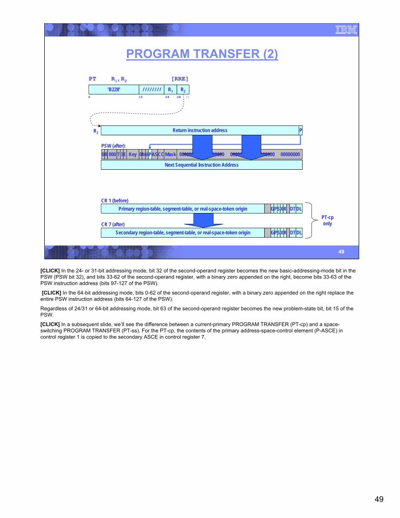
49
49
PROGRAM TRANSFER (2)
PT R1,R2 [RRE]
‘B228’ R2/ / / / / / / /0 16 24 31
R128
R2 Return instruction address PA/ / / / / / / / / / / / / / / / / / / / / / / / / / / / / / / /Return instruction address
Primary region-table, segment-table, or real-space-token origin GPSXR DTDLCR 1 (before)
Secondary region-table, segment-table, or real-space-token origin GPSXR DTDLCR 7 (after)
PSW (after):0R 000 T I E Key 0MWPAS MaskCC 0000000 EA 0000000 00000000 00000000 00000000
00000000 00000000 00000000 00000000 0 Next Sequential Instruction AddressNext Sequential Instruction Address
PT-cponly
[CLICK] In the 24- or 31-bit addressing mode, bit 32 of the second-operand register becomes the new basic-addressing-mode bit in the PSW (PSW bit 32), and bits 33-62 of the second-operand register, with a binary zero appended on the right, become bits 33-63 of the PSW instruction address (bits 97-127 of the PSW).
[CLICK] In the 64-bit addressing mode, bits 0-62 of the second-operand register, with a binary zero appended on the right replace the entire PSW instruction address (bits 64-127 of the PSW).
Regardless of 24/31 or 64-bit addressing mode, bit 63 of the second-operand register becomes the new problem-state bit, bit 15 of the PSW.
[CLICK] In a subsequent slide, we’ll see the difference between a current-primary PROGRAM TRANSFER (PT-cp) and a space-switching PROGRAM TRANSFER (PT-ss). For the PT-cp, the contents of the primary address-space-control element (P-ASCE) in control register 1 is copied to the secondary ASCE in control register 7.
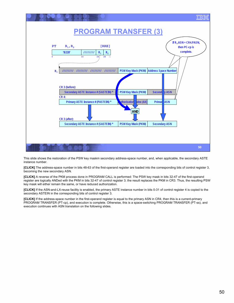
50
50
PROGRAM TRANSFER (3)
PT R1,R2 [RRE]
‘B228’ R2/ / / / / / / /0 16 24 31
R128
CR 3 (before):Secondary ASTE Instance # (SASTEIN) * PSW Key Mask (PKM) Secondary ASN
CR 4:Primary ASTE Instance # (PASTEIN) * Authorization Index (AX) Primary ASN
CR 3 (after):Secondary ASTE Instance # (SASTEIN) * PSW Key Mask (PKM) Secondary ASN
AND
Address Space NumberPSW Key Mask (PKM)/ / / / / / / / / / / / / / / / / / / / / / / / / / / / / / / /R1
If R1.ASN = CR4.PASN, then PC-cp is
complete.
This slide shows the restoration of the PSW key maskm secondary address-space number, and, when applicable, the secondary ASTE instance number.
[CLICK] The address-space number in bits 48-63 of the first-operand register are loaded into the corresponding bits of control register 3, becoming the new secondary ASN.
[CLICK] A reverse of the PKM process done in PROGRAM CALL is performed: The PSW key mask in bits 32-47 of the first-operand register are logically ANDed with the PKM in bits 32-47 of control register 3; the result replaces the PKM in CR3. Thus, the resulting PSW key mask will either remain the same, or have reduced authorization.
[CLICK] If the ASN-and-LX-reuse facility is enabled, the primary ASTE instance number in bits 0-31 of control register 4 is copied to the secondary ASTEIN in the corresponding bits of control register 3.
[CLICK] If the address-space number in the first-operand register is equal to the primary ASN in CR4, then this is a current-primary PROGRAM TRANSFER (PT-cp), and execution is complete. Otherwise, this is a space-switching PROGRAM TRANSFER (PT-ss), and execution continues with ASN translation on the following slides.

51
51
ASN Translation
Performed by:► LOAD ADDRESS SPACE PARAMETERS (LASP)► PROGRAM TRANSFER (PT) with space switching► PROGRAM TRANSFER WITH INSTANCE (PTI) with space
switching► SET SECONDARY ASN (SSAR) with space switching► SET SECONDARY ASN WITH INSTANCE (SSAIR) with space
switching16-bit address-space number► Operand of respective instructions► Determines new ASCE and ASN loaded into control registers
In a space-switching PROGRAM CALL, the new ASN is in the ETE (which is controlled by the OS). In the case of certain instructions such as a space-switching PROGRAM TRANSFER (and the others listed on this slide), the program supplies an address-space number as an operand in a register or in a storage location. Being program supplied – perhaps by an application program -- the ASN supplied to PT cannot be trusted to be authorized for use by the program.
The ASN-translation process is a means by which the 16-bit ASN provided by these instructions can be used to locate control structures provided by the operating system that (a) determine authorization, and (b) provide context information on the corresponding address space.
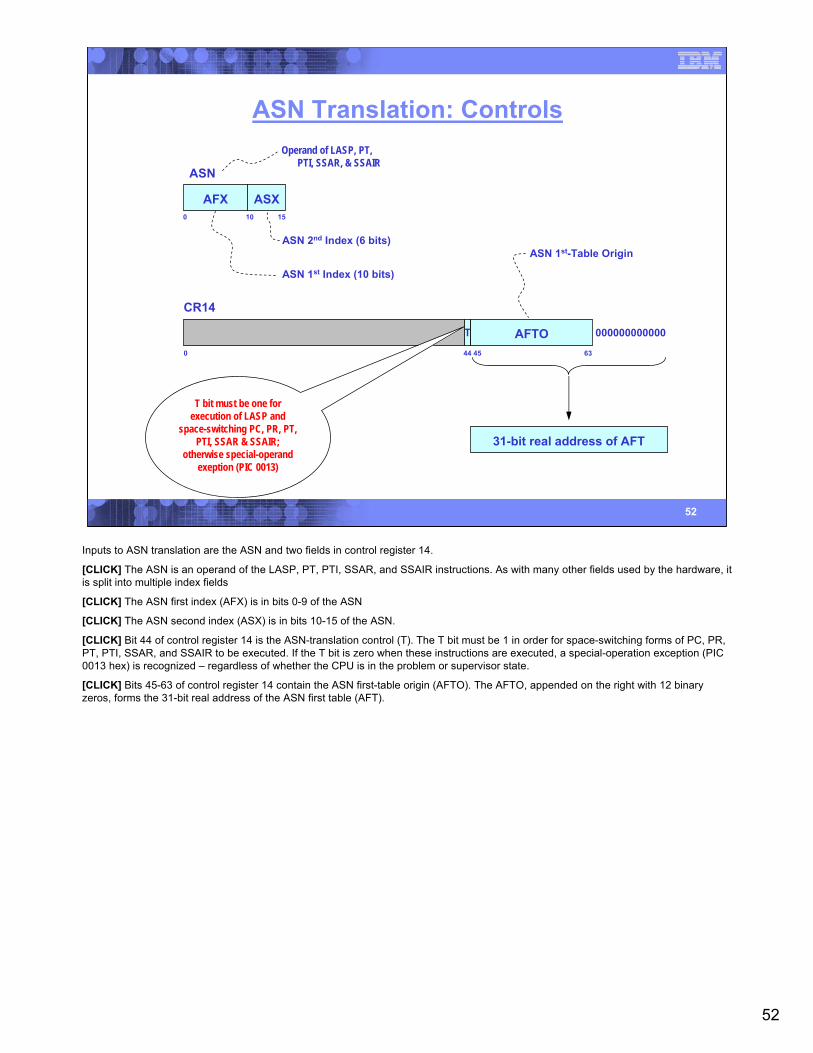
52
52
ASN Translation: Controls
ASN
AFX ASX0 10 15
000000000000
63
CR14
T AFTO44 450
31-bit real address of AFT
ASN 1st Index (10 bits)
ASN 2nd Index (6 bits)ASN 1st-Table Origin
Operand of LASP, PT,PTI, SSAR, & SSAIR
T bit must be one for execution of LASP and
space-switching PC, PR, PT, PTI, SSAR & SSAIR;
otherwise special-operand exeption (PIC 0013)
Inputs to ASN translation are the ASN and two fields in control register 14.
[CLICK] The ASN is an operand of the LASP, PT, PTI, SSAR, and SSAIR instructions. As with many other fields used by the hardware, it is split into multiple index fields
[CLICK] The ASN first index (AFX) is in bits 0-9 of the ASN
[CLICK] The ASN second index (ASX) is in bits 10-15 of the ASN.
[CLICK] Bit 44 of control register 14 is the ASN-translation control (T). The T bit must be 1 in order for space-switching forms of PC, PR, PT, PTI, SSAR, and SSAIR to be executed. If the T bit is zero when these instructions are executed, a special-operation exception (PIC 0013 hex) is recognized – regardless of whether the CPU is in the problem or supervisor state.
[CLICK] Bits 45-63 of control register 14 contain the ASN first-table origin (AFTO). The AFTO, appended on the right with 12 binary zeros, forms the 31-bit real address of the ASN first table (AFT).

53
53
ASN Translation: OperationASN
AFX ASX
Control Register 14
T AFTO(x 4096) (x 4)
ASN 1st Table
(x 64)
ASN 2nd Table
ASN 2nd-Table Entry (ASTE)
+
+(x 64)
I ASTO 000000
ASN 1st-Table Entry (ASTE)`
Operand of LASP, PT,PTI, SSAR, & SSAIR
Invalid bit (I) must be zero; otherwise, and
AFX-translation exception (PIC 0020)
As shown on the preceding slide, the givens to ASN translation are the ASN (from one of the instructions that cause ASN translation) and the ASN-first-table origin (AFTO) in control register 14.
[CLICK] The AFTO, multiplied by 4,096, points to the first byte of the ASN first table (AFT).
[CLICK] The ASN first index (AFX, bits 0-9 of the ASN), multiplied by 4, are added to the AFTO to locate an ASN-first-table entry (AFTE).
[CLICK] Bit 0 of the AFTE is the invalid bit. This bit must be zero, otherwise an AFX-translation exception is recognized (PIC 0020 hex).
[CLICK] If the AFTE is valid, bits 1-25 of the entry, appended on the right with six binary zeros, form the 31-bit real address of the ASN second table (AST).
[CLICK] The ASN second index, bits 10-15 of the ASN, multiplied by 64, form the address of an ASN second table entry (ASTE). This ASTE is the result of ASN translation.
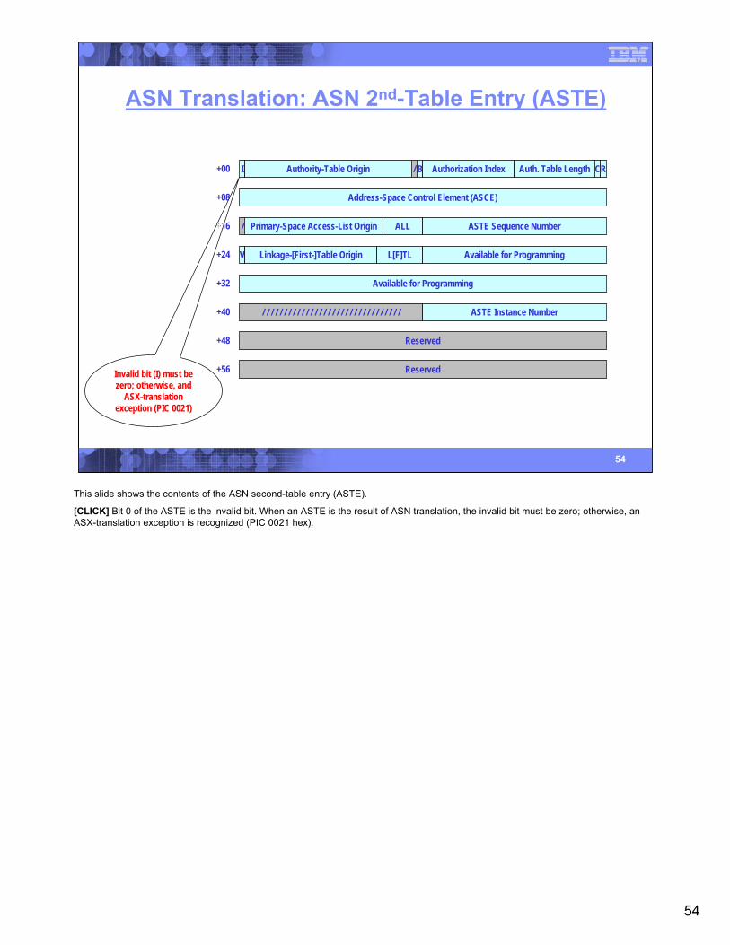
54
54
ASN Translation: ASN 2nd-Table Entry (ASTE)
I Authority-Table Origin / B Authorization Index Auth. Table Length CR
Address-Space Control Element (ASCE)
Primary-Space Access-List Origin/ ALL ASTE Sequence Number
V Linkage-[First-]Table Origin L[F]TL Available for Programming
Available for Programming
/ / / / / / / / / / / / / / / / / / / / / / / / / / / / / / / / ASTE Instance Number
Reserved
Reserved
+00
+08
+16
+24
+32
+40
+48
+56Invalid bit (I) must be zero; otherwise, and
ASX-translation exception (PIC 0021)
This slide shows the contents of the ASN second-table entry (ASTE).
[CLICK] Bit 0 of the ASTE is the invalid bit. When an ASTE is the result of ASN translation, the invalid bit must be zero; otherwise, an ASX-translation exception is recognized (PIC 0021 hex).
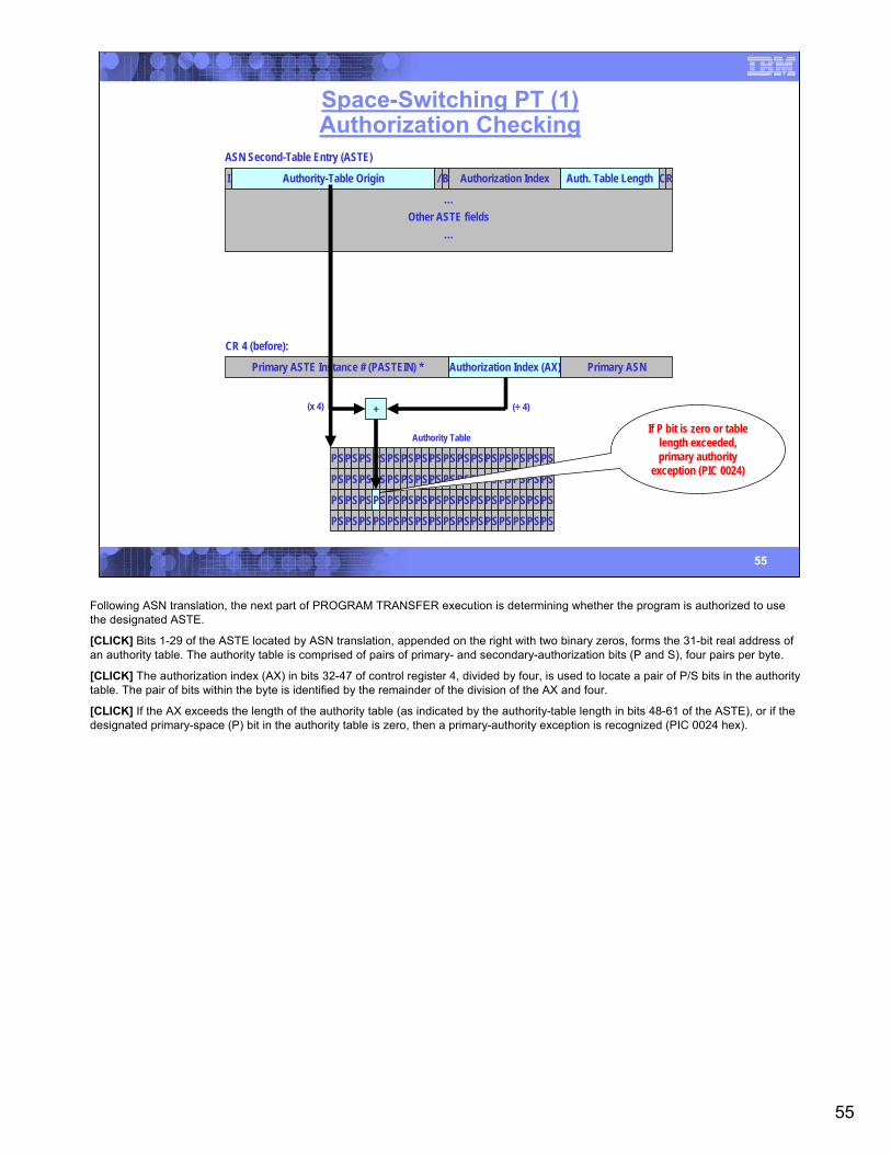
55
55
Space-Switching PT (1)Authorization Checking
CR 4 (before):
Primary ASTE Instance # (PASTEIN) * Authorization Index (AX) Primary ASN
I Authority-Table Origin / B Authorization Index Auth. Table Length CR
…Other ASTE fields
…
ASN Second-Table Entry (ASTE)
+
PSPS PSPS PSPS PSPS PSPS PSPS PSPS PSPS
PSPS PSPS PSPS PSPS PSPS PSPS PSPS PSPS
PSPS PSPS PSPS PSPS PSPS PSPS PSPS PSPS
PSPS PSPS PSPS PSPS PSPS PSPS PSPS PSPS
Authority Table
P
(÷ 4)(x 4)
If P bit is zero or table length exceeded, primary authority
exception (PIC 0024)
Following ASN translation, the next part of PROGRAM TRANSFER execution is determining whether the program is authorized to use the designated ASTE.
[CLICK] Bits 1-29 of the ASTE located by ASN translation, appended on the right with two binary zeros, forms the 31-bit real address of an authority table. The authority table is comprised of pairs of primary- and secondary-authorization bits (P and S), four pairs per byte.
[CLICK] The authorization index (AX) in bits 32-47 of control register 4, divided by four, is used to locate a pair of P/S bits in the authority table. The pair of bits within the byte is identified by the remainder of the division of the AX and four.
[CLICK] If the AX exceeds the length of the authority table (as indicated by the authority-table length in bits 48-61 of the ASTE), or if the designated primary-space (P) bit in the authority table is zero, then a primary-authority exception is recognized (PIC 0024 hex).
56
56
Space-Switching PT (2)
CR 4 (after):
Primary ASTE Instance # (PASTEIN) * Authorization Index (AX) Primary ASN
I Authority-Table Origin / B Authorization Index Auth. Table Length CR
Address-Space Control Element (ASCE)
Primary-Space Access-List Origin/ ALL ASTE Sequence Number
V Linkage-[First-]Table Origin L[F]TL Available for Programming
Available for Programming
/ / / / / / / / / / / / / / / / / / / / / / / / / / / / / / / / ASTE Instance Number
Reserved
Reserved
ASN Second-Table Entry (ASTE)
CR 3 (after):Secondary ASTE Instance # (SASTEIN) * Set by PT-cp processing
Address Space NumberPSW Key Mask (PKM)/ / / / / / / / / / / / / / / / / / / / / / / / / / / / / / / /
R1 (operand of PT instruction)
I Authority-Table Origin / B Authorization Index Auth. Table Length CR
Address-Space Control Element (ASCE)
Primary-Space Access-List Origin/ ALL ASTE Sequence Number
V Linkage-[First-]Table Origin L[F]TL Available for Programming
Available for Programming
/ / / / / / / / / / / / / / / / / / / / / / / / / / / / / / / / ASTE Instance Number
Reserved
Reserved
ASN Second-Table Entry (ASTE)
(when ASN-and-LX-reusefacility installed & enabled)
Assuming that the program is authorized to switch to this primary ASN (see previous slide), the following occurs:
[CLICK] The address-space number in bits 48-63 of the first-operand register is placed into the corresponding bits of control register 4.
[CLICK] The authorization index in bytes 4-5 of the ASTE (located by ASN translation) is placed into bits 32-47 of control register 4.
[CLICK] When the ASN-and-LX-reuse facility is enabled, the ASTE instance number in bytes 44-47 of the ASTE are placed in both the primary and secondary ASTEIN fields in control registers 4 and 3, respectively.
57
57
Space-Switching PT (3)
ASN Second-Table Entry (ASTE)
I Authority-Table Origin / B Authorization Index Auth. Table Length CR
Address-Space Control Element (ASCE)
Primary-Space Access-List Origin/ ALL ASTE Sequence Number
V Linkage-[First-]Table Origin L[F]TL Available for Programming
Available for Programming
/ / / / / / / / / / / / / / / / / / / / / / / / / / / / / / / / ASTE Instance Number
Reserved
Reserved
ASN Second-Table Entry (ASTE)
000000Primary ASTE Origin (PASTEO)CR 5 (after):
Primary region-table, segment-table, or real-space-token origin GPSXR DTDLCR 1 (after):
Secondary region-table, segment-table, or real-space-token origin GPSXR DTDLCR 7 (after):
Address of ASTE placed in CR 5.
The final operations in a space-switching PROGRAM TRANSFER are as follows:
[CLICK] The address-space control element (ASCE) in bytes 8-15 of the ASCE (located by ASN translation) is placed into both the primary and secondary ASCE fields in control registers 1 and 7, respectively.
[CLICK] The address of the ASTE (located by ASN translation) is placed into control register 5, becoming the new primary ASTE origin (PASTEO).
This completes the execution of a space-switching PROGRAM TRANSFER.
58
58
SET ADDRESS SPACE CONTROL
SACF D2(B2) [S]
‘B279’0 16 20 31
B2
Condition code: The code is unchanged Program exceptions:• Privileged-operation if attempt to set home space in the
problem state• Space-switch event• Special-operation exception if DAT is off or secondary-
space control (bit 37 of CR0) is off• Specification (invalid code)
D2
2nd-operand address:
0000 0000 0000 0000 0000 0000 00000000 0000 0000 0000 0000 0000 0000 0000 00000 56 60 63
Code Mode PSW.16-170 Primary space 001 Secondary space 102 Access register 013 Home space 11>3 Invalid
SAC D2(B2) [S]
‘B219’0 16 20 31
B2 D2
Code
SET ADDRESS SPACE CONTROL (SAC) and SET ADDRESS SPACE CONTROL FAST (SACF) are both used to set the addressing mode in bits 16-17 of the PSW.
[CLICK] The storage operand of these instructions is not used to access storage.
[CLICK] Rather, bits 56-59 of the operand address form a code that is used to determine the setting of address-space control bits in the PSW, as shown.
The primary difference between SAC and SACF are that SAC performs a serialization and checkpoint-synchronization operation before begins and after the operation completes; SACF performs neither serialization nor checkpoint synchronization. Additionally, it is unpredictable whether SACF checks the secondary-space control in bit 37 of CR0.
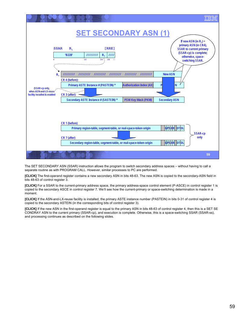
59
59
SET SECONDARY ASN (1)
SSAR R1 [RRE]
‘B228’ / / / // / / / / / / /0 16 24 31
R128
Primary region-table, segment-table, or real-space-token origin GPSXR DTDLCR 1 (before)
Secondary region-table, segment-table, or real-space-token origin GPSXR DTDLCR 7 (after)
SSAR-cponly
New ASN/ / / / / / / / / / / / / / / / / / / / / / / / / / / / / / / / / / / / / / / / / / / / / / / /R1
CR 3 (after):Secondary ASTE Instance # (SASTEIN) * PSW Key Mask (PKM) Secondary ASN
CR 4 (before):Primary ASTE Instance # (PASTEIN) * Authorization Index (AX) Primary ASN
If new ASN (in R1) = primary ASN (in CR4),
SSAR to current primary (SSAR-cp) is complete;
otherwise, space-switching SSAR.
(SSAR-cp only,when ASN-and-LX-reuse
facility installed & enabled
The SET SECONDARY ASN (SSAR) instruction allows the program to switch secondary address spaces – without having to call a separate routine as with PROGRAM CALL. However, similar processes to PC are performed.
[CLICK] The first-operand register contains a new secondary ASN in bits 48-63. The new ASN is copied to the secondary-ASN field in bits 48-63 of control register 3.
[CLICK] For a SSAR to the current-primary address space, the primary address-space control element (P-ASCE) in control register 1 is copied to the secondary ASCE in control register 7. We’ll see how the current-primary or space-switching determination is made in a moment.
[CLICK] If the ASN-and-LX-reuse facility is installed, the primary ASTE instance number (PASTEIN) in bits 0-31 of control register 4 is copied to the secondary ASTEIN (in the corresponding bits of control register 3).
[CLICK] If the new ASN in the first-operand register is equal to the primary ASN in bits 48-63 of control register 4, then this is a SET SE CONDRAY ASN to the current primary (SSAR-cp), and execution is complete. Otherwise, this is a space-switching SSAR (SSAR-ss), and processing continues as described on the following slides.

60
60
SET SECONDARY ASN (2)Space-Switching Authorization Checking
CR 4 (before):
Primary ASTE Instance # (PASTEIN) * Authorization Index (AX) Primary ASN
I Authority-Table Origin / B Authorization Index Auth. Table Length CR
…Other ASTE fields
…
ASTE (located via ASN translation of the ASN in R1 – à la PT)
+
PSPS PSPS PSPS PSPS PSPS PSPS PSPS PSPS
PSPS PSPS PSPS PSPS PSPS PSPS PSPS PSPS
PSPS PSPS PSPS PSPS PSPS PSPS PSPS PSPS
PSPS PSPS PSPS PSPS PSPS PSPS PSPS PSPS
Authority Table
S
(÷ 4)(x 4)
If S bit is zero or table length exceeded,
secondary authority exception (PIC 0025)
For a space-switching SSAR, the designated ASN is translated, as described in operation of PROGRAM TRANSFER. If ASN-translation is successful, a new secondary ASTE is located.
ASN authorization proceeds in a manner similar to that of PROGRAM TRANSFER, except that a secondary-authority bit (the second bit in the P/S pair of bits) is examined.
[CLICK] If the authorization index in bits 32-47 of control register 4 exceeds the length of the authority table (in bits 48-61 of the ASTE located by ASN translation), or if the S bit designated by the AX is zero, then a secondary-authority exception is recognized (PIC 0025 hex)
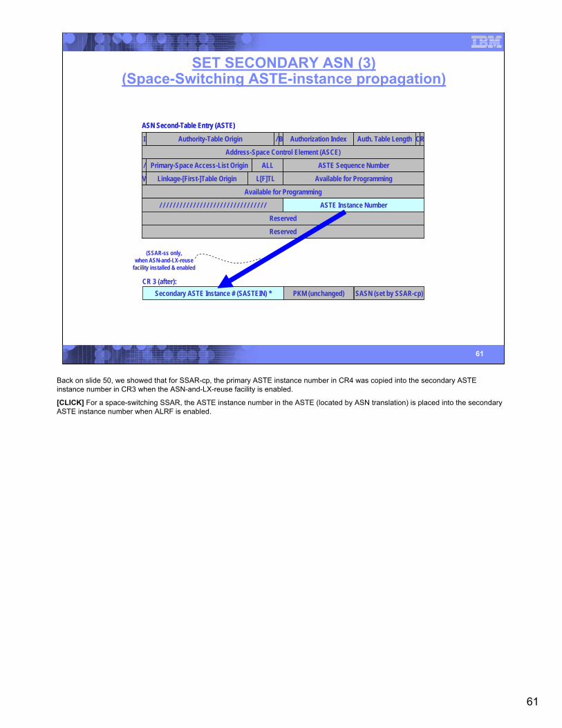
61
61
SET SECONDARY ASN (3)(Space-Switching ASTE-instance propagation)
ASN Second-Table Entry (ASTE)
I Authority-Table Origin / B Authorization Index Auth. Table Length CR
Address-Space Control Element (ASCE)
Primary-Space Access-List Origin/ ALL ASTE Sequence Number
V Linkage-[First-]Table Origin L[F]TL Available for Programming
Available for Programming
/ / / / / / / / / / / / / / / / / / / / / / / / / / / / / / / / ASTE Instance Number
Reserved
Reserved
ASN Second-Table Entry (ASTE)
CR 3 (after):Secondary ASTE Instance # (SASTEIN) * PKM (unchanged) SASN (set by SSAR-cp)
(SSAR-ss only,when ASN-and-LX-reuse
facility installed & enabled
Back on slide 50, we showed that for SSAR-cp, the primary ASTE instance number in CR4 was copied into the secondary ASTE instance number in CR3 when the ASN-and-LX-reuse facility is enabled.
[CLICK] For a space-switching SSAR, the ASTE instance number in the ASTE (located by ASN translation) is placed into the secondary ASTE instance number when ALRF is enabled.
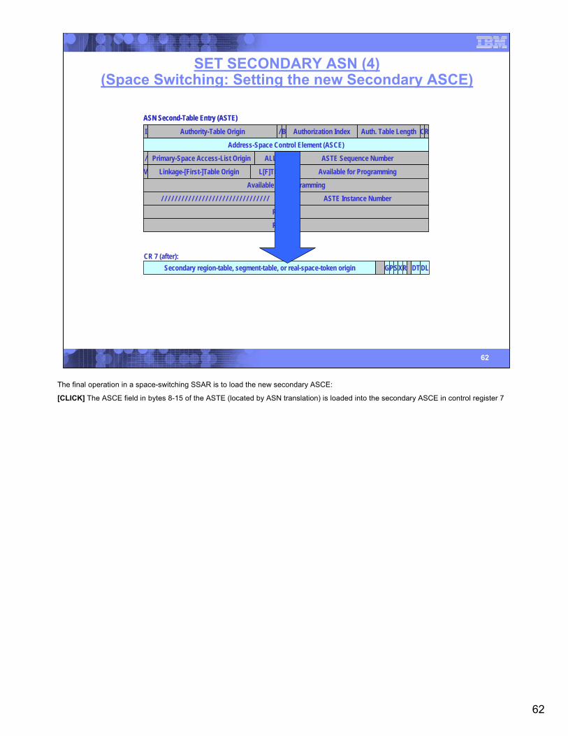
62
62
SET SECONDARY ASN (4)(Space Switching: Setting the new Secondary ASCE)
ASN Second-Table Entry (ASTE)
I Authority-Table Origin / B Authorization Index Auth. Table Length CR
Address-Space Control Element (ASCE)
Primary-Space Access-List Origin/ ALL ASTE Sequence Number
V Linkage-[First-]Table Origin L[F]TL Available for Programming
Available for Programming
/ / / / / / / / / / / / / / / / / / / / / / / / / / / / / / / / ASTE Instance Number
Reserved
Reserved
ASN Second-Table Entry (ASTE)
Secondary region-table, segment-table, or real-space-token origin GPSXR DTDLCR 7 (after):
The final operation in a space-switching SSAR is to load the new secondary ASCE:
[CLICK] The ASCE field in bytes 8-15 of the ASTE (located by ASN translation) is loaded into the secondary ASCE in control register 7
63
63
zOS PC-Related MacrosATEXT – Extract authorization index
ATSET – Set authorization table
AXEXT – Extract authorization index
AXFRE – Free authorization index
AXRES – Reserve authorization index
AXSET – Set authorization index
ETCON – Entry table connection
ETCRE – Create entry table
ETCON – Create an entry-table descriptor
ETDES – Destroy an entry table
ETDIS – Disconnect an entry table
LXFRE – Free a linkage index
LXRES – Reserve a linkage index
See MVS Programming: Authorized Assembler Services Reference (volumes 1-4) andMVS Programming: Extended Addressability Guide for details
z/OS provides a robust suite of macro instructions for the construction and management of the various hardware tables used in a dual-address-space environment. This slide provides an inventory of some of these macro instructions.
For more details, please refer to the following documents:
• zOS MVS Programming: Authorized Assembler Services Reference, Volume 1 (ALE-DYN) [SA22-7609]
• zOS MVS Programming: Authorized Assembler Services Reference, Volume 2 (EDT-IXG) [SA22-7610]
• zOS MVS Programming: Authorized Assembler Services Reference, Volume 3 (LLA-SDU) [SA22-7611]
• zOS MVS Programming: Authorized Assembler Services Reference, Volume 4 (SET-WTO) [SA22-7612]
• zOS MVS Programming: Extended Addressability Guide [SA22-7614]
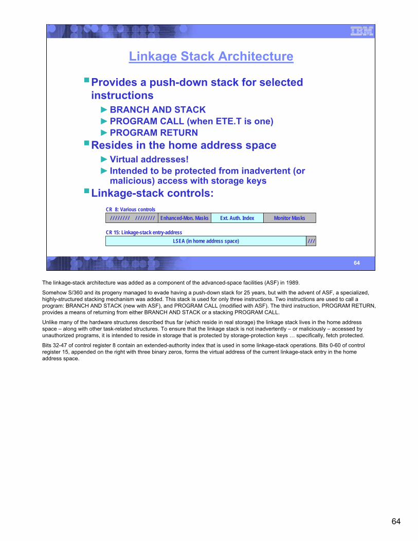
64
64
Linkage Stack Architecture
Provides a push-down stack for selected instructions►BRANCH AND STACK►PROGRAM CALL (when ETE.T is one)►PROGRAM RETURN
Resides in the home address space►Virtual addresses!► Intended to be protected from inadvertent (or
malicious) access with storage keysLinkage-stack controls:
/ / /LSEA (in home address space)CR 15: Linkage-stack entry-address
CR 8: Various controlsEnhanced-Mon. Masks/ / / / / / / / / / / / / / / / Ext. Auth. Index Monitor Masks
The linkage-stack architecture was added as a component of the advanced-space facilities (ASF) in 1989.
Somehow S/360 and its progeny managed to evade having a push-down stack for 25 years, but with the advent of ASF, a specialized, highly-structured stacking mechanism was added. This stack is used for only three instructions. Two instructions are used to call a program: BRANCH AND STACK (new with ASF), and PROGRAM CALL (modified with ASF). The third instruction, PROGRAM RETURN, provides a means of returning from either BRANCH AND STACK or a stacking PROGRAM CALL.
Unlike many of the hardware structures described thus far (which reside in real storage) the linkage stack lives in the home address space – along with other task-related structures. To ensure that the linkage stack is not inadvertently – or maliciously – accessed by unauthorized programs, it is intended to reside in storage that is protected by storage-protection keys … specifically, fetch protected.
Bits 32-47 of control register 8 contain an extended-authority index that is used in some linkage-stack operations. Bits 0-60 of control register 15, appended on the right with three binary zeros, forms the virtual address of the current linkage-stack entry in the home address space.

65
65
Linkage Stack Structure
Home Address Space
Header
State Entry
Trailer
State Entry
State Entry
State Entry
State Entry
CR 15LS Entry Addr.
Header
State Entry
Trailer
State Entry
Free space
Header
State Entry
Trailer
State Entry
State Entry
State Entry
State Entry
Header
Trailer
Free space
Stack Section(up to 64K)
This slide begins by illustrating a linkage-stack section.
[CLICK] A linkage-stack section may be up to 64 K-bytes in size, each section containing a 16-byte header and trailer entry, and zero or more state entries that are created by stacking PROGRAM CALL or BRANCH AND STACK.
[CLICK] The trailer entry in a stack section may contain a pointer to a subsequent section (along with a forward-pointer validity indication).
[CLICK] The header entry in a subsequent section contains a pointer to the last valid state entry in the previous section (along with abackward-pointer validity indication). Additional stack sections may be chained as shown.
[CLICK] Control register 15 points to the (end of) the last valid state entry. As shown here, there may be additional space in the state entry that is unused.
[CLICK] In fact, there may be additional stack sections beyond that last valid state entry, however only the forward pointers are relevant to these entries.

66
66
Linkage Stack Entries (1)
Entry Descriptor
U Unstack-suppression controlET Entry type:
0001001: header0001010: trailer0001100: branch-state entry0001101: PC state entry
SI Section identificationRFS Remaining free spaceNES Next-entry size
RFSU ET SI NES / / / / / / / / / / / / / / / /0 1 8 16 32 48 63
Four types of entriesLast doubleword of each entry is an entry descriptor (ED)
Each linkage-stack entry is followed by an eight-byte entry descriptor, as shown here. The entry descriptor comprises the following:
• The unstack-suppression bit (U), when one, prevents the unstacking of the entry. This bit is inspected by the CPU during PROGRAM RETURN operations, but the CPU does not set it. Rather, an operating system may set this bit for diagnostic or tracing purposes.
• The entry type (ET) is a seven bit field, encoded as shown. There are four entry types: header, trailer, branch-state, and PC-state.
• An eight-bit stack-identification (SI) field is intended to uniquely entries within a particular stack section. The operating system is expected to place a unique ID in the header and trailer entries of a stack section. As new branch- or PC-state entries are placed on the stack, the CPU will propagate the SI field to the entry descriptors for the new entries.
• The remaining-free space indicates how many free bytes appear between the current entry and the trailer entry in a stack section. In fact, RFS indicates the number of bytes from the ED to the trailer entry; the concept of free space is meaningful only in the last state entry of a section.
• Next entry size is meaningful in all but the last state entry and trailer entry in a stack section.
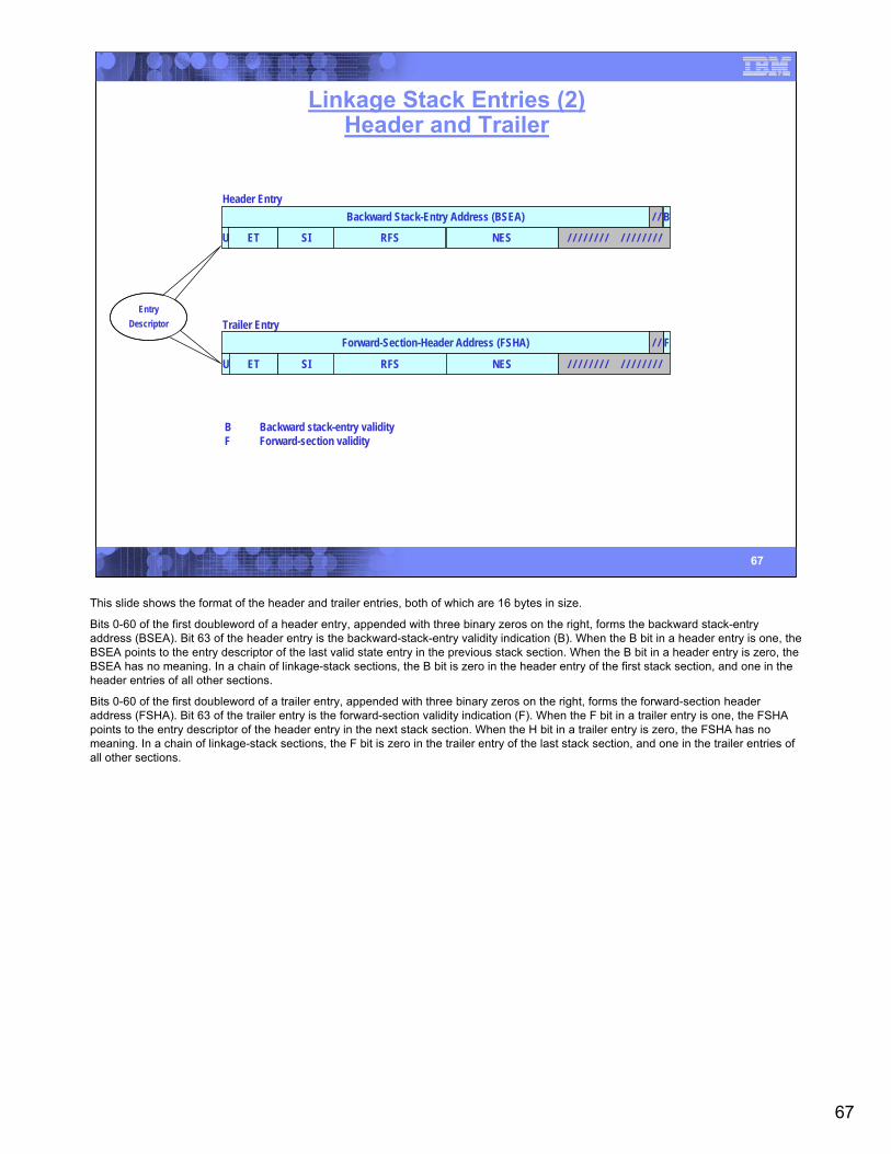
67
67
Linkage Stack Entries (2)Header and Trailer
B Backward stack-entry validityF Forward-section validity
Header EntryBackward Stack-Entry Address (BSEA) B/ /
Trailer EntryForward-Section-Header Address (FSHA) F/ /
RFSU ET SI NES / / / / / / / / / / / / / / / /
RFSU ET SI NES / / / / / / / / / / / / / / / /
EntryDescriptor
This slide shows the format of the header and trailer entries, both of which are 16 bytes in size.
Bits 0-60 of the first doubleword of a header entry, appended with three binary zeros on the right, forms the backward stack-entry address (BSEA). Bit 63 of the header entry is the backward-stack-entry validity indication (B). When the B bit in a header entry is one, the BSEA points to the entry descriptor of the last valid state entry in the previous stack section. When the B bit in a header entry is zero, the BSEA has no meaning. In a chain of linkage-stack sections, the B bit is zero in the header entry of the first stack section, and one in the header entries of all other sections.
Bits 0-60 of the first doubleword of a trailer entry, appended with three binary zeros on the right, forms the forward-section header address (FSHA). Bit 63 of the trailer entry is the forward-section validity indication (F). When the F bit in a trailer entry is one, the FSHA points to the entry descriptor of the header entry in the next stack section. When the H bit in a trailer entry is zero, the FSHA has no meaning. In a chain of linkage-stack sections, the F bit is zero in the trailer entry of the last stack section, and one in the trailer entries of all other sections.
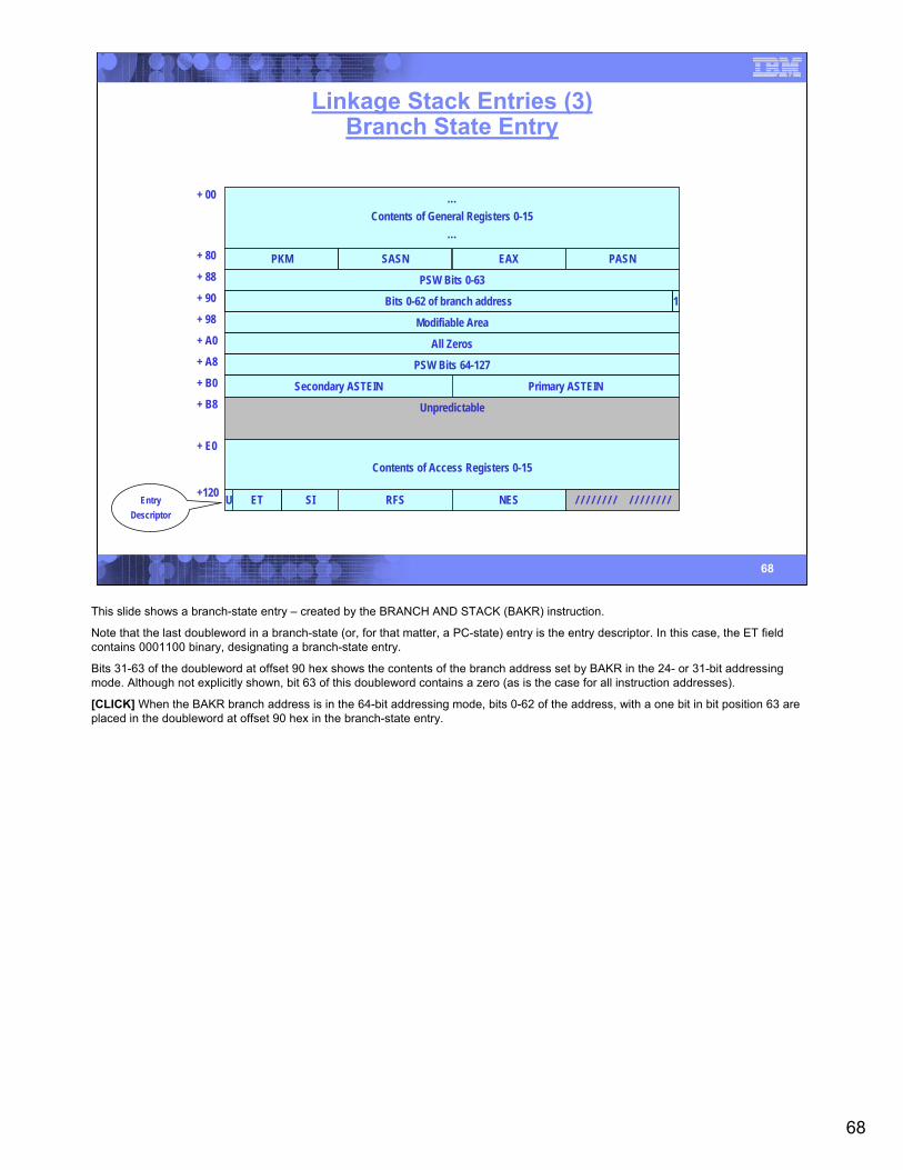
68
68
Linkage Stack Entries (3)Branch State Entry
…Contents of General Registers 0-15
…
PKM SASN EAX PASN
+ 00
+ 80
PSW Bits 0-63+ 88
+ 90 / / / / / / / / / / / / / / / / / / / / / / / / / / / / / / / / Bits 33-63 of branch addressA 1Bits 0-62 of branch address
Modifiable Area+ 98
All Zeros+ A0
PSW Bits 64-127+ A8
+ B0 Secondary ASTEIN Primary ASTEIN
Unpredictable+ B8
Contents of Access Registers 0-15
+ E0
+120 RFSU ET SI NES / / / / / / / / / / / / / / / /EntryDescriptor
This slide shows a branch-state entry – created by the BRANCH AND STACK (BAKR) instruction.
Note that the last doubleword in a branch-state (or, for that matter, a PC-state) entry is the entry descriptor. In this case, the ET fieldcontains 0001100 binary, designating a branch-state entry.
Bits 31-63 of the doubleword at offset 90 hex shows the contents of the branch address set by BAKR in the 24- or 31-bit addressing mode. Although not explicitly shown, bit 63 of this doubleword contains a zero (as is the case for all instruction addresses).
[CLICK] When the BAKR branch address is in the 64-bit addressing mode, bits 0-62 of the address, with a one bit in bit position 63 are placed in the doubleword at offset 90 hex in the branch-state entry.

69
69
Linkage Stack Entries (4)PC State Entry
+ 00
+ 80
+ 88
+ 90
+ 98
+ A0
+ A8
+ B0
+ B8
+ E0
+120
…Contents of General Registers 0-15
…
PKM SASN EAX PASN
PSW Bits 0-63
Called-Space ID Numeric Part of PC Number?
Modifiable Area
All Zeros
PSW Bits 64-127
Secondary ASTEIN Primary ASTEIN
Unpredictable
Contents of Access Registers 0-15
RFSU ET SI NES / / / / / / / / / / / / / / / /EntryDescriptor
Resulting AMODE:0: 24- or 31-bit mode1: 64-bit mode
Here we see the format of a PC-state entry. The size, and the majority of the content are identical to that of the branch-state entry. However, a key difference is in the doubleword at offset 90 hex.
In the PC-state entry, the word at offset 90 hex contains the called-space ID. As we saw in the discussion of stacking PROGRAM CALL, the called-space ID is a combination of the target address-space number (ASN) and the rightmost 16 bits of the ASTE instance number.
Bits 1-31 of the word at offset 94 hex contain the numeric portion of the PC number. If you recall from the discussion of the PC number, when the ASN-and-LX-reuse facility is installed, the PC number is a 32-bit value in the rightmost 32 bits of the operand address of thePC instruction. However, bit 44 of this PC number is a flag field, indicating whether the LFX is a single entity or split. Thus, the PC number that is stacked has this flag bit removed, such that only the numeric portion of the PC number appears.
[CLICK] Bit 0 of the byte at location 94 hex contains a flag bit indicating the extended-addressing mode of the called program.
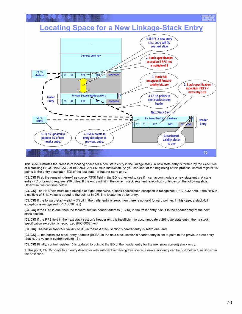
70
70
Locating Space for a New Linkage-Stack Entry
TrailerEntry
RFSU ET SI NES //////// ////////
F
RFSU ET SI NES //////// ////////
Forward Section Header Address //
Current State Entry
CR 15(before)
…
1. If RFS ≥ new entry size, entry will fit;
see next slide
2. Stack-specification exception if RFS not
a multiple of 8
3. Stack-full exception if forward-
validity bit zero
CR 15(after)
RFSU ET SI NES //////// ////////
BBackward Stack-Entry Address // HeaderEntry
Next Stack Section
5. Stack-specification exception if RFS <
new entry size4. FSHA points to next stack section
header
7. BSEA points to entry descriptor of
previous entry.
8. CR 15 updated to point to ED of new
header entry.
6. Backward-validity bit set
to one
This slide illustrates the process of locating space for a new state entry in the linkage stack. A new state entry is formed by the execution of a stacking PROGRAM CALL or BRANCH AND STACK instruction. As you can see, at the beginning of this process, control register 15 points to the entry descriptor (ED) of the last state- or header-state entry.
[CLICK] First, the remaining-free-free space (RFS) field in the ED is checked to see if it can accommodate a new state entry. A state entry (PC or branch) requires 296 bytes. If the entry will fit in the current stack segment, execution continues on the following slide. Otherwise, we continue below.
[CLICK] The RFS field must be a multiple of eight; otherwise, a stack-specification exception is recognized. (PIC 0032 hex). If the RFS is a multiple of 8, its value is added to the pointer in CR15 to locate the trailer entry.
[CLICK] If the forward-stack-validity (F) bit in the trailer entry is zero, then there is no valid forward pointer. In this case, a stack-full exception is recognized. (PIC 0030 hex)
[CLICK] If the F bit is one, then the forward-section header address (FSHA) in the trailer entry points to the header entry of the next stack section.
[CLICK] If the RFS field in the next stack section’s header entry is insufficient to accommodate a 296-byte state entry, then a stack-specification exception is recotnized (PIC 0032 hex)
[CLICK] The backward-stack validity bit (B) in the next stack section’s header entry is set to one, and …
[CLICK] … the backward-stack-entry-address (BSEA) in the next stack section’s header entry is set to point to the previous state entry (that is, the value in control register 15).
[CLICK] Finally, control register 15 is updated to point to the ED of the header entry for the next (now current) stack entry.
At this point, CR 15 points to an entry descriptor with sufficient remaining free space; a new stack entry can be built below it, as shown in the next slide.
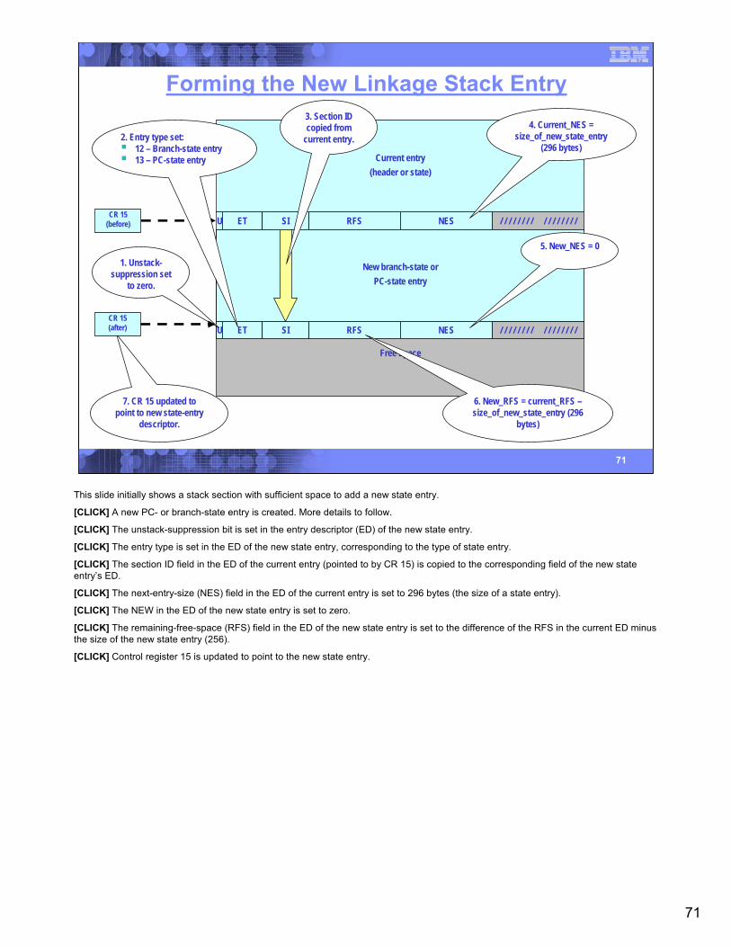
71
71
Forming the New Linkage Stack Entry
RFSU ET SI NES / / / / / / / / / / / / / / / /CR 15
(before)
Current entry(header or state)
Free space
New branch-state orPC-state entry
RFSU ET SI NES / / / / / / / / / / / / / / / /
4. Current_NES = size_of_new_state_entry
(296 bytes)
5. New_NES = 01. Unstack-
suppression set to zero.
2. Entry type set:12 – Branch-state entry13 – PC-state entry
3. Section ID copied from
current entry.
6. New_RFS = current_RFS –size_of_new_state_entry (296
bytes)
7. CR 15 updated to point to new state-entry
descriptor.
CR 15(after)
This slide initially shows a stack section with sufficient space to add a new state entry.
[CLICK] A new PC- or branch-state entry is created. More details to follow.
[CLICK] The unstack-suppression bit is set in the entry descriptor (ED) of the new state entry.
[CLICK] The entry type is set in the ED of the new state entry, corresponding to the type of state entry.
[CLICK] The section ID field in the ED of the current entry (pointed to by CR 15) is copied to the corresponding field of the new stateentry’s ED.
[CLICK] The next-entry-size (NES) field in the ED of the current entry is set to 296 bytes (the size of a state entry).
[CLICK] The NEW in the ED of the new state entry is set to zero.
[CLICK] The remaining-free-space (RFS) field in the ED of the new state entry is set to the difference of the RFS in the current ED minus the size of the new state entry (256).
[CLICK] Control register 15 is updated to point to the new state entry.
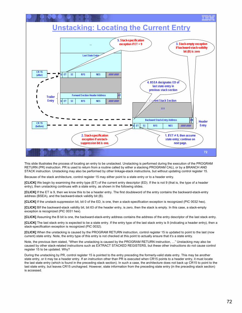
72
72
Unstacking: Locating the Current Entry
CR 15(after)
CR 15(before) RFSU ET SI NES //////// ////////
???
Current Stack Section
Last State Entry
…
TrailerEntry RFSU ET SI NES //////// ////////
Forward Section Header Address F//
RFSU ET SI NES //////// ////////
HeaderEntry
BBackward Stack-Entry Address //
1. If ET ≠ 9, then assume state entry; continue on
next page.
2. Stack-specification exception if unstack-
suppression bit is one.
3. Stack-empty exception if backward-stack-validity
bit (B) is zero
4. BSEA designates ED of last state entry in
previous stack section
5. Stack-specification exception if ET = 9
This slide illustrates the process of locating an entry to be unstacked. Unstacking is performed during the execution of the PROGRAM RETURN (PR) instruction. PR is used to return from a routine called by either a stacking PROGRAM CALL or by a BRANCH AND STACK instruction. Unstacking may also be performed by other linkage-stack instructions, but without updating control register 15.
Because of the stack architecture, control register 15 may either point to a state entry or to a header entry.
[CLICK] We begin by examining the entry type (ET) of the current entry descriptor (ED). If the is not 9 (that is, the type of a header entry), then unstacking continues with a state entry, as shown in the following slides.
[CLICK] If the ET is 9, then we know this to be a header entry. The first doubleword of the entry contains the backward-stack-entry address (BSEA), and the backward-stack validity bit (B).
[CLICK] If the unstack-suppression bit, bit 0 of the ED, is one, then a stack-specification exception is recognized (PIC 0032 hex).
[CLICK] BIf the backward-stack validity bit, bit 63 of the header entry, is zero, then the stack is empty. In this case, a stack-empty exception is recognized (PIC 0031 hex).
[CLICK] Assuming the B bit is one, the backward-stack-entry address contains the address of the entry descriptor of the last stack entry.
[CLICK] The last stack entry is expected to be a state entry. If the entry type of the last stack entry is 9 (indicating a header entry), then a stack-specification exception is recognized (PIC 0032).
[CLICK] When the unstacking is caused by the PROGRAM RETURN instruction, control register 15 is updated to point to the last (now current) state entry. Note, the entry type of this entry is not checked at this point to actually ensure that it’s a state entry.
Note, the previous item stated, “When the unstacking is caused by the PROGRAM RETURN instruction, …” Unstacking may also be caused by other stack-related instructions such as EXTRACT STACKED REGISTERS, but these other instructions do not cause control register 15 to be updated. Why?
During the unstacking by PR, control register 15 is pointed to the entry preceding the formerly-valid state entry. This may be another state entry, or it may be a header entry. If an instruction other than PR is executed when CR15 points to a header entry, it must locate the last state entry (which is found in the preceding stack section). In such a case, the architecture does not back up CR15 to point to the last state entry, but leaves CR15 unchagned. However, state information from the preceding state entry (in the preceding stack section) is accessed.
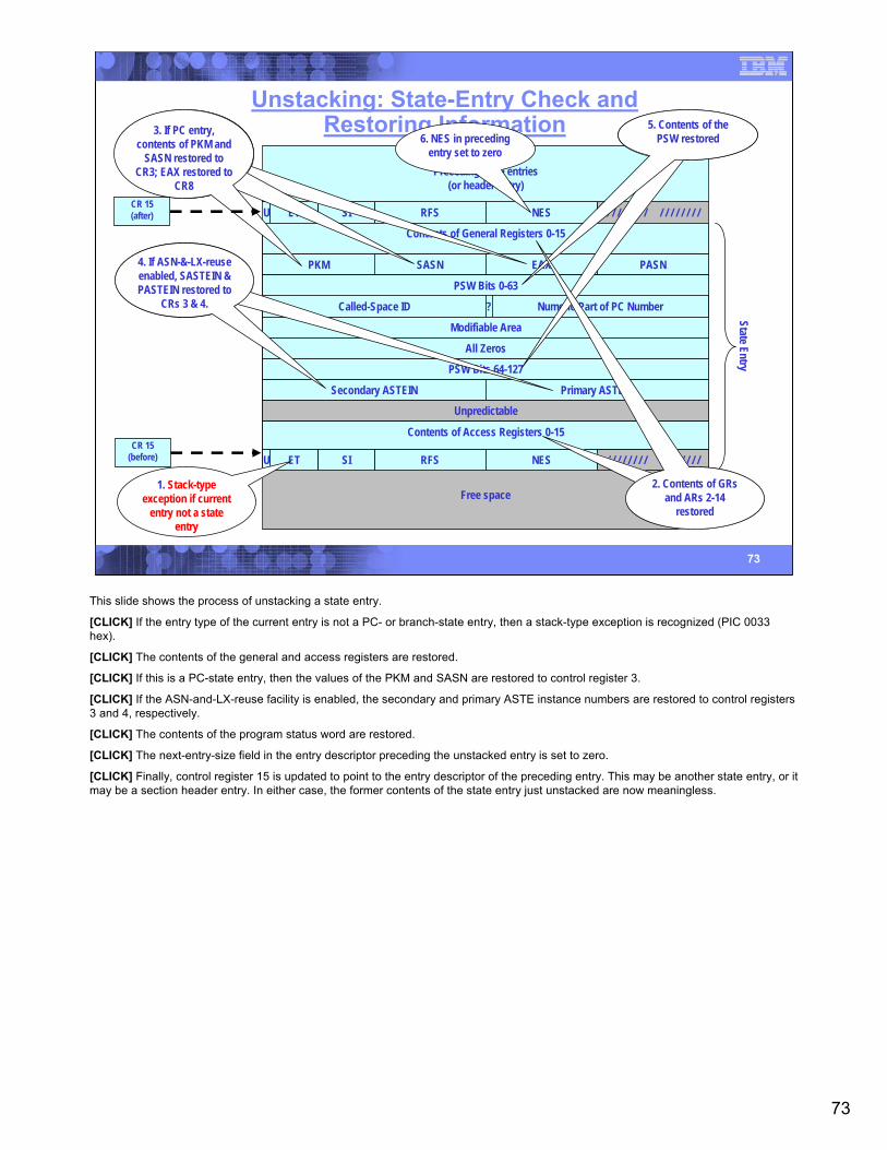
73
73
Unstacking: State-Entry Check andRestoring Information
RFSU ET SI NES / / / / / / / / / / / / / / / /
Preceding state entries(or header entry)
Free space
Contents of General Registers 0-15
PKM SASN EAX PASN
PSW Bits 0-63
Called-Space ID Numeric Part of PC Number?
Modifiable Area
All Zeros
PSW Bits 64-127
Secondary ASTEIN Primary ASTEIN
Unpredictable
Contents of Access Registers 0-15
RFSU ET SI NES / / / / / / / / / / / / / / / /
State Entry6. NES in preceding
entry set to zero
1. Stack-type exception if current
entry not a state entry
3. If PC entry, contents of PKM and
SASN restored to CR3; EAX restored to
CR8
4. If ASN-&-LX-reuse enabled, SASTEIN & PASTEIN restored to
CRs 3 & 4.
5. Contents of the PSW restored
2. Contents of GRsand ARs 2-14
restored
CR 15(before)
CR 15(after)
This slide shows the process of unstacking a state entry.
[CLICK] If the entry type of the current entry is not a PC- or branch-state entry, then a stack-type exception is recognized (PIC 0033 hex).
[CLICK] The contents of the general and access registers are restored.
[CLICK] If this is a PC-state entry, then the values of the PKM and SASN are restored to control register 3.
[CLICK] If the ASN-and-LX-reuse facility is enabled, the secondary and primary ASTE instance numbers are restored to control registers 3 and 4, respectively.
[CLICK] The contents of the program status word are restored.
[CLICK] The next-entry-size field in the entry descriptor preceding the unstacked entry is set to zero.
[CLICK] Finally, control register 15 is updated to point to the entry descriptor of the preceding entry. This may be another state entry, or it may be a section header entry. In either case, the former contents of the state entry just unstacked are now meaningless.

74
74
Linkage Stack Instructions
BRANCH AND STACKEXTRACT STACKED REGISTERSEXTRACT STACKED STATEMODIFY STACKED STATEPROGRAM CALL (when ETE.T is one)PROGRAM RETURN
This slide lists the instructions related to the linkage-stack architecture. We’ll examine each of these on the following slides.
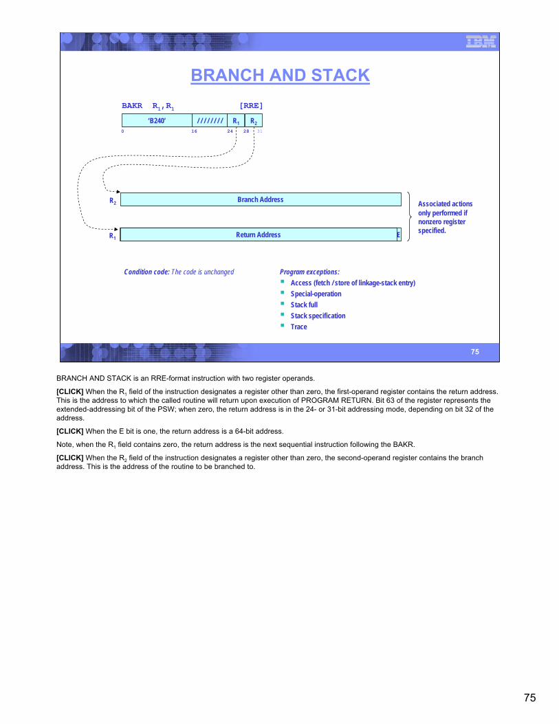
75
75
BRANCH AND STACK
Condition code: The code is unchanged Program exceptions:Access (fetch / store of linkage-stack entry)Special-operation Stack fullStack specificationTrace
BAKR R1,R1 [RRE]
‘B240’0 16 24 31
R2/ / / / / / / / R128
R2 Branch Address
R1 Return Address EA/ / / / / / / / / / / / / / / / / / / / / / / / / / / / / / / /Return Address
Associated actionsonly performed ifnonzero registerspecified.
BRANCH AND STACK is an RRE-format instruction with two register operands.
[CLICK] When the R1 field of the instruction designates a register other than zero, the first-operand register contains the return address. This is the address to which the called routine will return upon execution of PROGRAM RETURN. Bit 63 of the register represents the extended-addressing bit of the PSW; when zero, the return address is in the 24- or 31-bit addressing mode, depending on bit 32 of the address.
[CLICK] When the E bit is one, the return address is a 64-bit address.
Note, when the R1 field contains zero, the return address is the next sequential instruction following the BAKR.
[CLICK] When the R2 field of the instruction designates a register other than zero, the second-operand register contains the branch address. This is the address of the routine to be branched to.
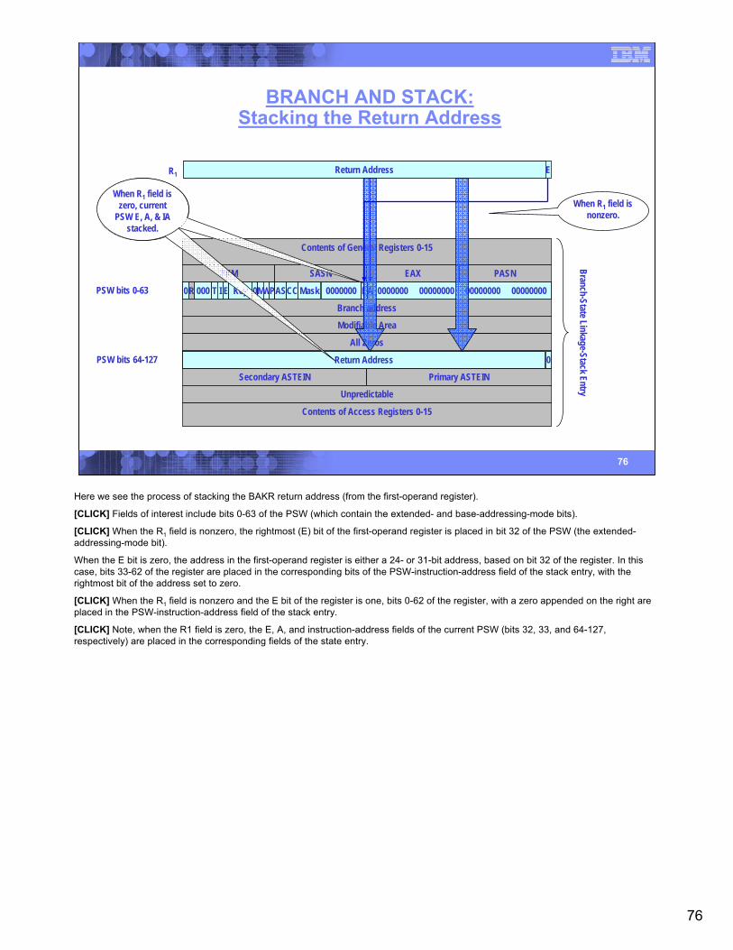
76
76
BRANCH AND STACK:Stacking the Return Address
R1 Return Address EA/ / / / / / / / / / / / / / / / / / / / / / / / / / / / / / / /
Contents of General Registers 0-15
PKM SASN EAX PASN
Modifiable Area
All Zeros
Secondary ASTEIN Primary ASTEIN
Unpredictable
Contents of Access Registers 0-15
Branch-State Linkage-Stack Entry
PSW bits 0-63
PSW bits 64-127 0
Branch address
Return Address/ / / / / / / / / / / / / / / / / / / / / / / / / / / / / / / / /Return Address
Return Address
PSW Bits 0-630R 000 T I E Key 0MWPAS MaskCC 0000000 EA 0000000 00000000 00000000 00000000E
When R1 field is nonzero.
When R1 field is zero, current
PSW E, A, & IA stacked.
Here we see the process of stacking the BAKR return address (from the first-operand register).
[CLICK] Fields of interest include bits 0-63 of the PSW (which contain the extended- and base-addressing-mode bits).
[CLICK] When the R1 field is nonzero, the rightmost (E) bit of the first-operand register is placed in bit 32 of the PSW (the extended-addressing-mode bit).
When the E bit is zero, the address in the first-operand register is either a 24- or 31-bit address, based on bit 32 of the register. In this case, bits 33-62 of the register are placed in the corresponding bits of the PSW-instruction-address field of the stack entry, with the rightmost bit of the address set to zero.
[CLICK] When the R1 field is nonzero and the E bit of the register is one, bits 0-62 of the register, with a zero appended on the right are placed in the PSW-instruction-address field of the stack entry.
[CLICK] Note, when the R1 field is zero, the E, A, and instruction-address fields of the current PSW (bits 32, 33, and 64-127, respectively) are placed in the corresponding fields of the state entry.
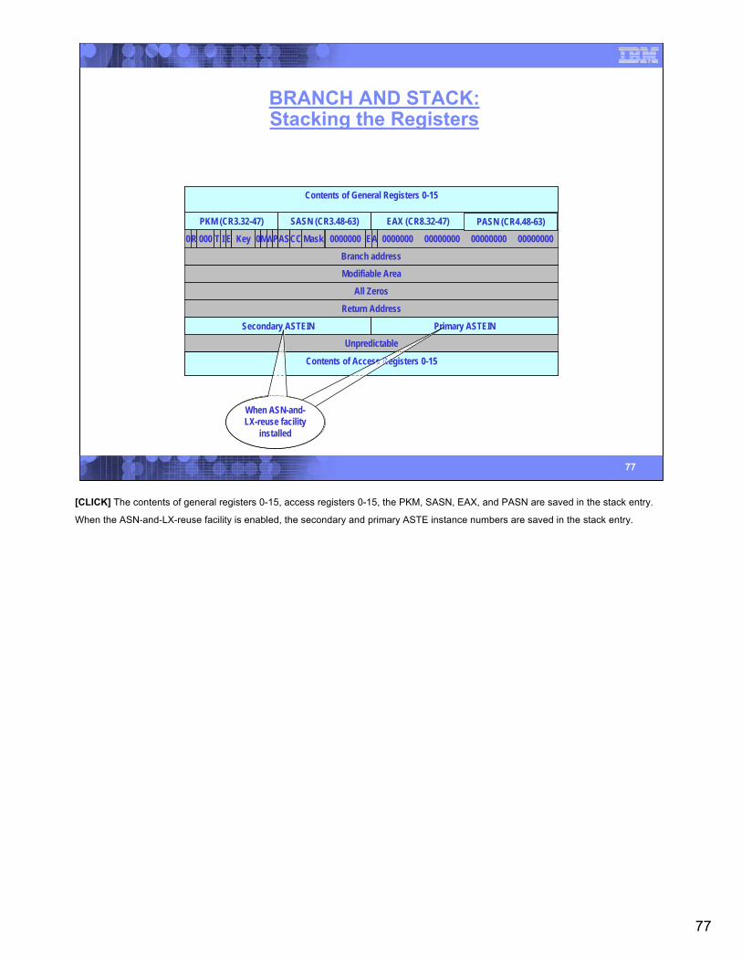
77
77
BRANCH AND STACK:Stacking the Registers
Modifiable Area
All Zeros
Unpredictable
0R 000 T I E Key 0MWPAS MaskCC 0000000 EA 0000000 00000000 00000000 00000000
Branch address
Return Address
PKM (CR3.32-47) SASN (CR3.48-63) EAX (CR8.32-47) PASN (CR4.48-63)
Contents of General Registers 0-15
Secondary ASTEIN Primary ASTEIN
Contents of Access Registers 0-15
When ASN-and-LX-reuse facility
installed
[CLICK] The contents of general registers 0-15, access registers 0-15, the PKM, SASN, EAX, and PASN are saved in the stack entry.
When the ASN-and-LX-reuse facility is enabled, the secondary and primary ASTE instance numbers are saved in the stack entry.
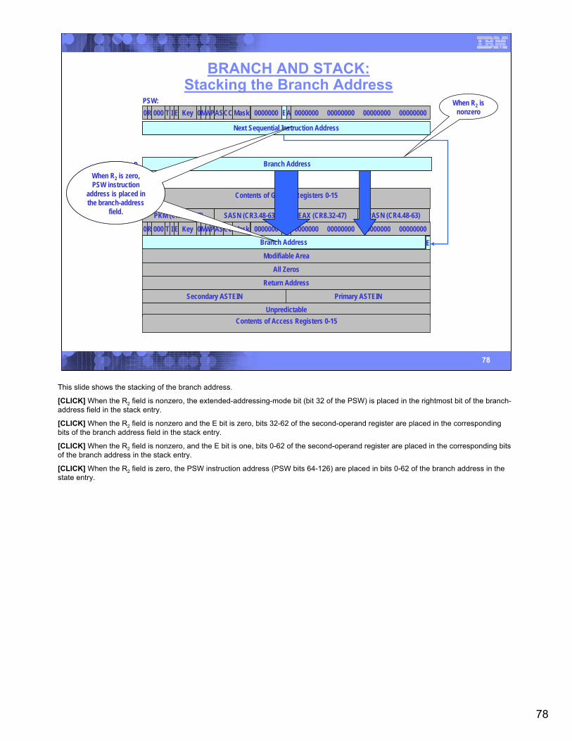
78
78
BRANCH AND STACK:Stacking the Branch Address
Modifiable Area
All Zeros
Unpredictable
0R 000 T I E Key 0MWPAS MaskCC 0000000 EA 0000000 00000000 00000000 00000000
Return Address
PKM (CR3.32-47) SASN (CR3.48-63) EAX (CR8.32-47) PASN (CR4.48-63)
Contents of General Registers 0-15
Secondary ASTEIN Primary ASTEIN
Contents of Access Registers 0-15
PSW:0R 000 T I E Key 0MWPAS MaskCC 0000000 EA 0000000 00000000 00000000 00000000
R2 00000000 00000000 00000000 00000000 0 Branch Address
00000000 00000000 00000000 00000000 0 Next Sequential Instruction Address
/ / / / / / / / / / / / / / / / / / / / / / / / / / / / / / / / / Branch Address EBranch Address
Branch Address
When R2 is nonzero
Next Sequential Instruction Address
When R2 is zero,PSW instruction
address is placed in the branch-address
field.
This slide shows the stacking of the branch address.
[CLICK] When the R2 field is nonzero, the extended-addressing-mode bit (bit 32 of the PSW) is placed in the rightmost bit of the branch-address field in the stack entry.
[CLICK] When the R2 field is nonzero and the E bit is zero, bits 32-62 of the second-operand register are placed in the corresponding bits of the branch address field in the stack entry.
[CLICK] When the R2 field is nonzero, and the E bit is one, bits 0-62 of the second-operand register are placed in the corresponding bits of the branch address in the stack entry.
[CLICK] When the R2 field is zero, the PSW instruction address (PSW bits 64-126) are placed in bits 0-62 of the branch address in the state entry.
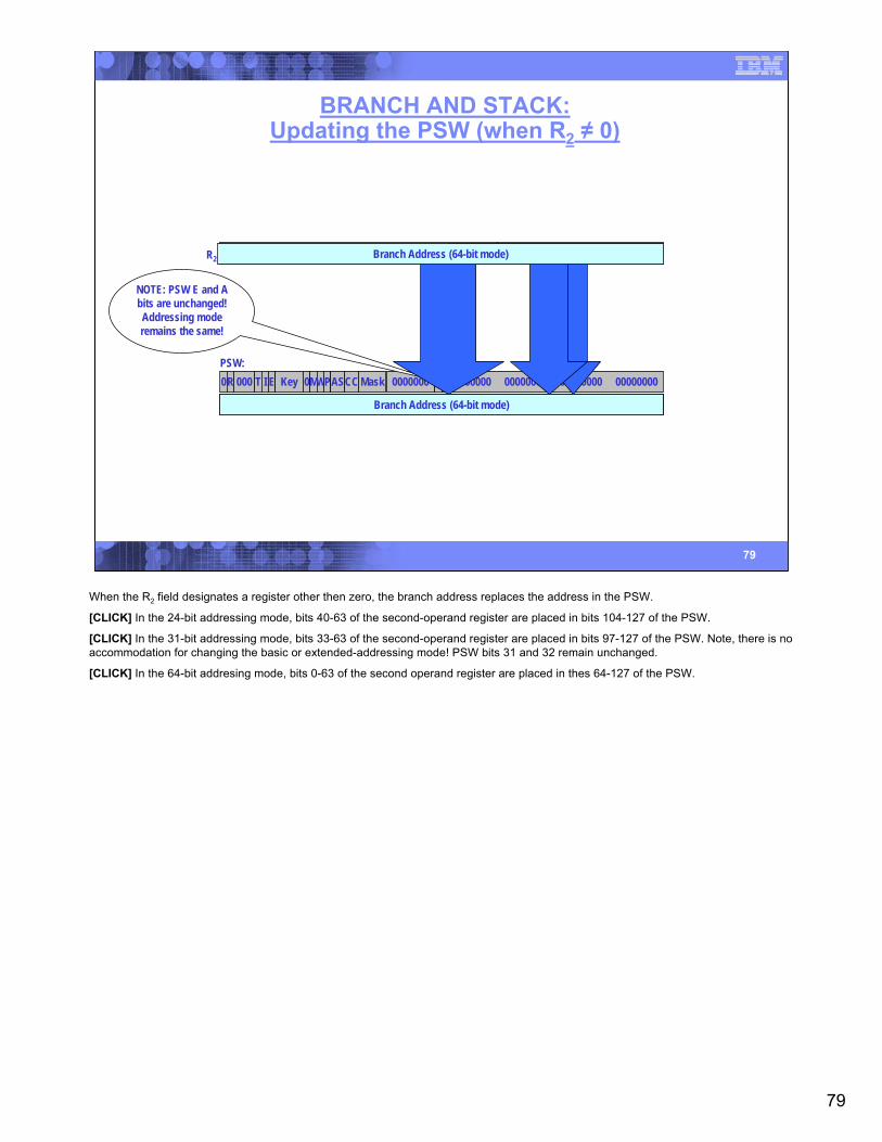
79
79
BRANCH AND STACK:Updating the PSW (when R2 ≠ 0)
PSW:0R 000 T I E Key 0MWPAS MaskCC 0000000 EA 0000000 00000000 00000000 00000000
00000000 00000000 00000000 00000000 00000000 Branch Address (24-bit mode)Branch Address (31-bit mode)
R2 Branch Address (24-bit mode)00000000 00000000 00000000 00000000 00000000
NOTE: PSW E and A bits are unchanged! Addressing mode remains the same!
Branch Address (31-bit mode)Branch Address (64-bit mode)
Branch Address (64-bit mode)
When the R2 field designates a register other then zero, the branch address replaces the address in the PSW.
[CLICK] In the 24-bit addressing mode, bits 40-63 of the second-operand register are placed in bits 104-127 of the PSW.
[CLICK] In the 31-bit addressing mode, bits 33-63 of the second-operand register are placed in bits 97-127 of the PSW. Note, there is no accommodation for changing the basic or extended-addressing mode! PSW bits 31 and 32 remain unchanged.
[CLICK] In the 64-bit addresing mode, bits 0-63 of the second operand register are placed in thes 64-127 of the PSW.
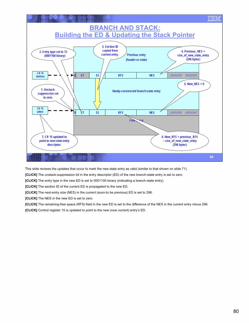
80
80
BRANCH AND STACK:Building the ED & Updating the Stack Pointer
RFSU ET SI NES / / / / / / / / / / / / / / / /CR 15
(before)
Previous entry(header or state)
Free space
Newly-constructed branch-state entry
RFSU ET SI NES / / / / / / / / / / / / / / / /
4. Previous_NES = size_of_new_state_entry
(296 bytes)
5. New_NES = 01. Unstack-
suppression set to zero.
2. Entry type set to 12 (0001100 binary)
3. Section ID copied from
current entry.
6. New_RFS = previous_RFS– size_of_new_state_entry
(296 bytes)
7. CR 15 updated to point to new state-entry
descriptor.
CR 15(after)
This slide reviews the updates that occur to mark the new state entry as valid (similar to that shown on slide 71).
[CLICK] The unstack-suppression bit in the entry descriptor (ED) of the new branch-state entry is set to zero.
[CLICK] The entry type in the new ED is set to 0001100 binary (indicating a branch-state entry).
[CLICK] The section ID of the current ED is propagated to the new ED.
[CLICK] The next-entry size (NES) in the current (soon-to be previous) ED is set to 296.
[CLICK] The NES in the new ED is set to zero.
[CLICK] The remaining-free space (RFS) field in the new ED is set to the difference of the NES in the current entry minus 296.
[CLICK] Control register 15 is updated to point to the new (now current) entry’s ED.
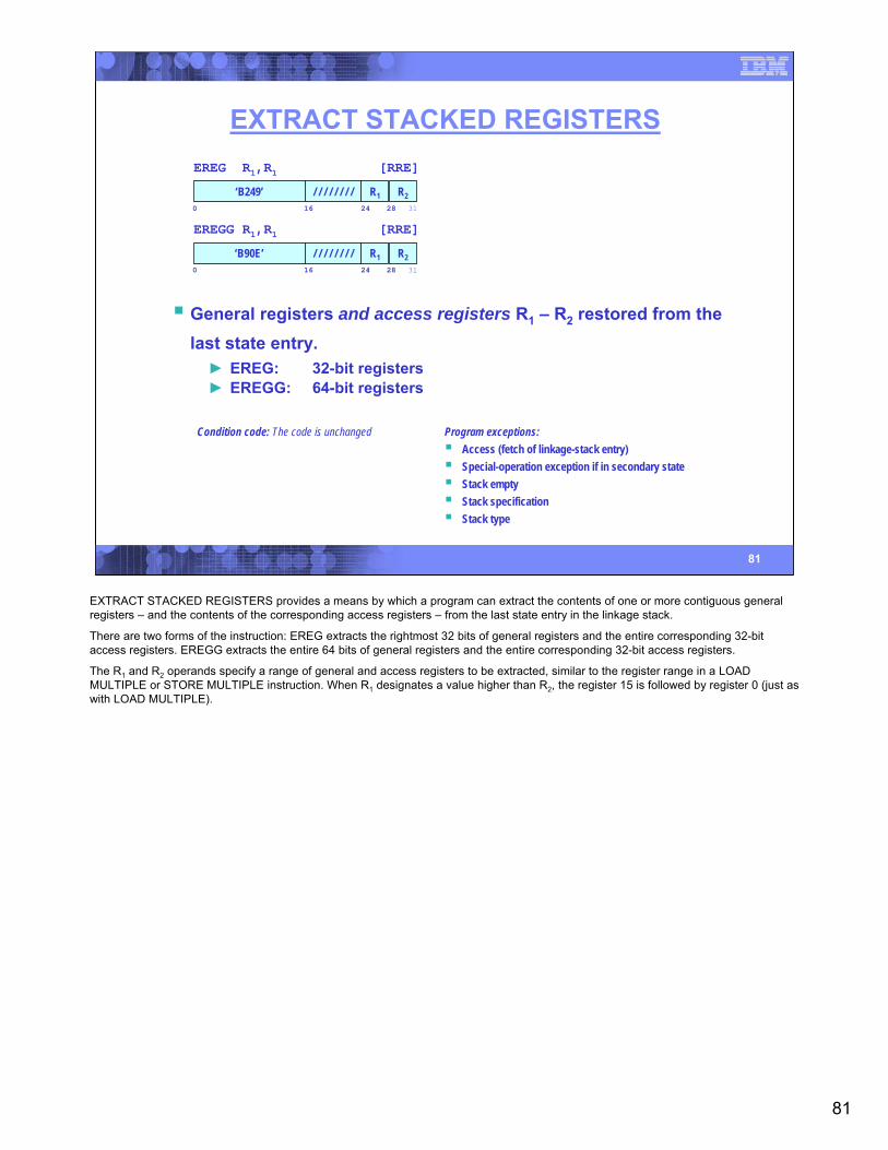
81
81
EXTRACT STACKED REGISTERS
Condition code: The code is unchanged Program exceptions:Access (fetch of linkage-stack entry)Special-operation exception if in secondary stateStack emptyStack specificationStack type
EREG R1,R1 [RRE]
‘B249’0 16 24 31
R2/ / / / / / / / R128
EREGG R1,R1 [RRE]
‘B90E’0 16 24 31
R2/ / / / / / / / R128
General registers and access registers R1 – R2 restored from the last state entry.► EREG: 32-bit registers► EREGG: 64-bit registers
EXTRACT STACKED REGISTERS provides a means by which a program can extract the contents of one or more contiguous general registers – and the contents of the corresponding access registers – from the last state entry in the linkage stack.
There are two forms of the instruction: EREG extracts the rightmost 32 bits of general registers and the entire corresponding 32-bit access registers. EREGG extracts the entire 64 bits of general registers and the entire corresponding 32-bit access registers.
The R1 and R2 operands specify a range of general and access registers to be extracted, similar to the register range in a LOAD MULTIPLE or STORE MULTIPLE instruction. When R1 designates a value higher than R2, the register 15 is followed by register 0 (just as with LOAD MULTIPLE).
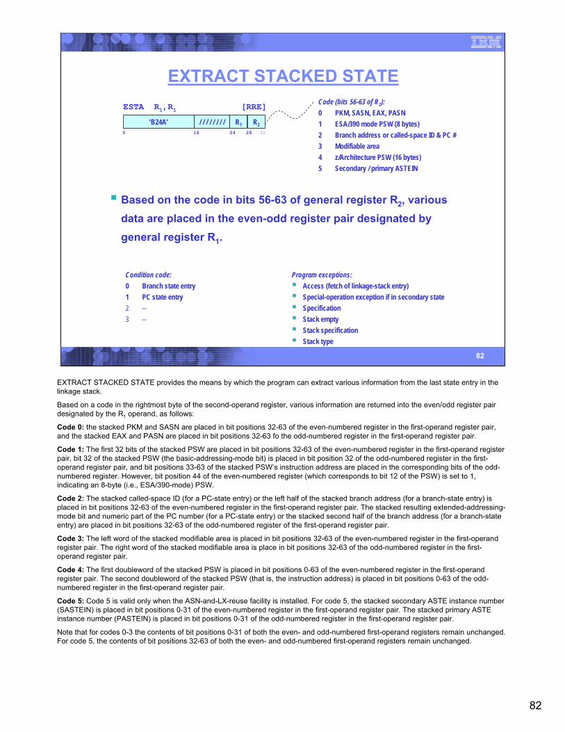
82
82
EXTRACT STACKED STATE
Condition code:0 Branch state entry1 PC state entry2 --3 --
Program exceptions:Access (fetch of linkage-stack entry)Special-operation exception if in secondary stateSpecificationStack emptyStack specificationStack type
ESTA R1,R1 [RRE]
‘B24A’0 16 24 31
R2/ / / / / / / / R128
Based on the code in bits 56-63 of general register R2, various data are placed in the even-odd register pair designated by general register R1.
Code (bits 56-63 of R2):0 PKM, SASN, EAX, PASN1 ESA/390 mode PSW (8 bytes)2 Branch address or called-space ID & PC #3 Modifiable area4 z/Architecture PSW (16 bytes)5 Secondary / primary ASTEIN
EXTRACT STACKED STATE provides the means by which the program can extract various information from the last state entry in the linkage stack.
Based on a code in the rightmost byte of the second-operand register, various information are returned into the even/odd register pair designated by the R1 operand, as follows:
Code 0: the stacked PKM and SASN are placed in bit positions 32-63 of the even-numbered register in the first-operand register pair, and the stacked EAX and PASN are placed in bit positions 32-63 fo the odd-numbered register in the first-operand register pair.
Code 1: The first 32 bits of the stacked PSW are placed in bit positions 32-63 of the even-numbered register in the first-operand register pair, bit 32 of the stacked PSW (the basic-addressing-mode bit) is placed in bit position 32 of the odd-numbered register in the first-operand register pair, and bit positions 33-63 of the stacked PSW’s instruction address are placed in the corresponding bits of the odd-numbered register. However, bit position 44 of the even-numbered register (which corresponds to bit 12 of the PSW) is set to 1, indicating an 8-byte (i.e., ESA/390-mode) PSW.
Code 2: The stacked called-space ID (for a PC-state entry) or the left half of the stacked branch address (for a branch-state entry) is placed in bit positions 32-63 of the even-numbered register in the first-operand register pair. The stacked resulting extended-addressing-mode bit and numeric part of the PC number (for a PC-state entry) or the stacked second half of the branch address (for a branch-state entry) are placed in bit positions 32-63 of the odd-numbered register of the first-operand register pair.
Code 3: The left word of the stacked modifiable area is placed in bit positions 32-63 of the even-numbered register in the first-operand register pair. The right word of the stacked modifiable area is place in bit positions 32-63 of the odd-numbered register in the first-operand register pair.
Code 4: The first doubleword of the stacked PSW is placed in bit positions 0-63 of the even-numbered register in the first-operand register pair. The second doubleword of the stacked PSW (that is, the instruction address) is placed in bit positions 0-63 of the odd-numbered register in the first-operand register pair.
Code 5: Code 5 is valid only when the ASN-and-LX-reuse facility is installed. For code 5, the stacked secondary ASTE instance number (SASTEIN) is placed in bit positions 0-31 of the even-numbered register in the first-operand register pair. The stacked primary ASTE instance number (PASTEIN) is placed in bit positions 0-31 of the odd-numbered register in the first-operand register pair.
Note that for codes 0-3 the contents of bit positions 0-31 of both the even- and odd-numbered first-operand registers remain unchanged. For code 5, the contents of bit positions 32-63 of both the even- and odd-numbered first-operand registers remain unchanged.
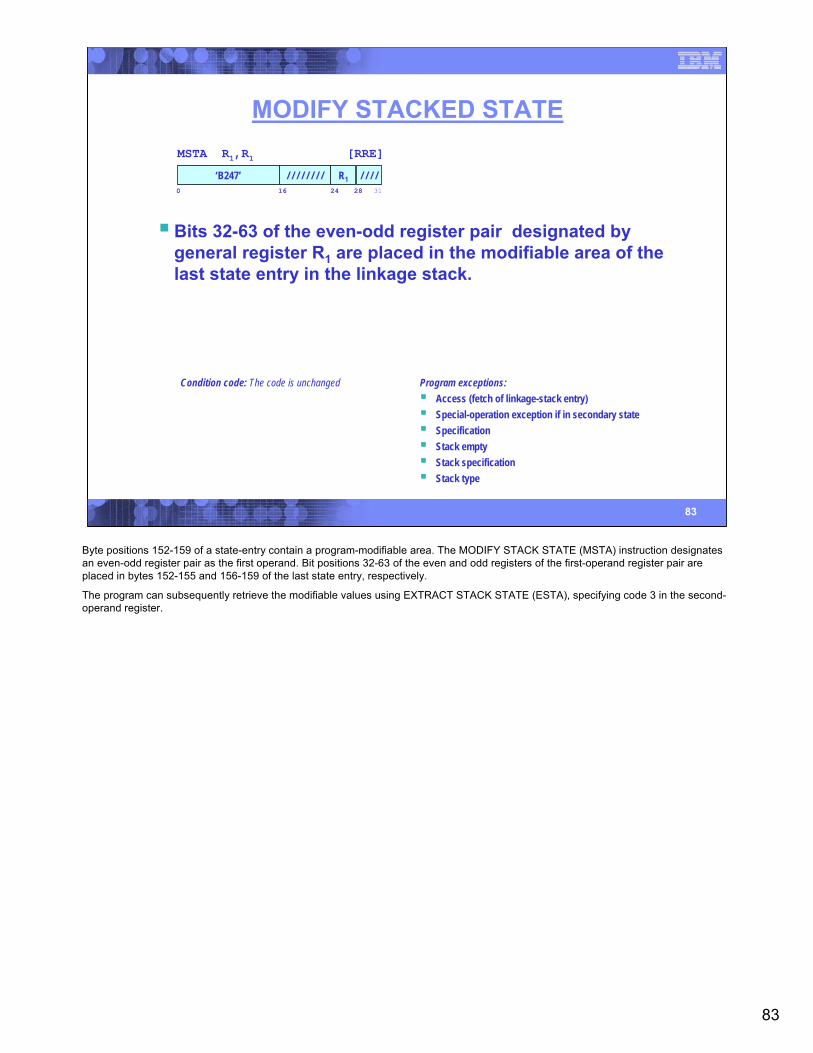
83
83
MODIFY STACKED STATE
Condition code: The code is unchanged Program exceptions:Access (fetch of linkage-stack entry)Special-operation exception if in secondary stateSpecificationStack emptyStack specificationStack type
MSTA R1,R1 [RRE]
‘B247’0 16 24 31
/ / / // / / / / / / / R128
Bits 32-63 of the even-odd register pair designated by general register R1 are placed in the modifiable area of the last state entry in the linkage stack.
Byte positions 152-159 of a state-entry contain a program-modifiable area. The MODIFY STACK STATE (MSTA) instruction designates an even-odd register pair as the first operand. Bit positions 32-63 of the even and odd registers of the first-operand register pair are placed in bytes 152-155 and 156-159 of the last state entry, respectively.
The program can subsequently retrieve the modifiable values using EXTRACT STACK STATE (ESTA), specifying code 3 in the second-operand register.
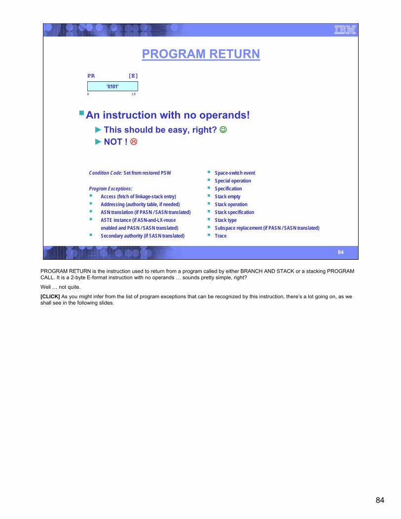
84
84
PROGRAM RETURN
Condition Code: Set from restored PSW
Program Exceptions:Access (fetch of linkage-stack entry)Addressing (authority table, if needed)ASN translation (if PASN / SASN translated)ASTE instance (if ASN-and-LX-reuse enabled and PASN / SASN translated)Secondary authority (if SASN translated)
Space-switch eventSpecial operationSpecificationStack emptyStack operationStack specificationStack typeSubspace replacement (if PASN / SASN translated)Trace
PR [E]
‘0101’0 15
An instruction with no operands!►This should be easy, right? ☺►NOT !
PROGRAM RETURN is the instruction used to return from a program called by either BRANCH AND STACK or a stacking PROGRAM CALL. It is a 2-byte E-format instruction with no operands … sounds pretty simple, right?
Well … not quite.
[CLICK] As you might infer from the list of program exceptions that can be recognized by this instruction, there’s a lot going on, as we shall see in the following slides.
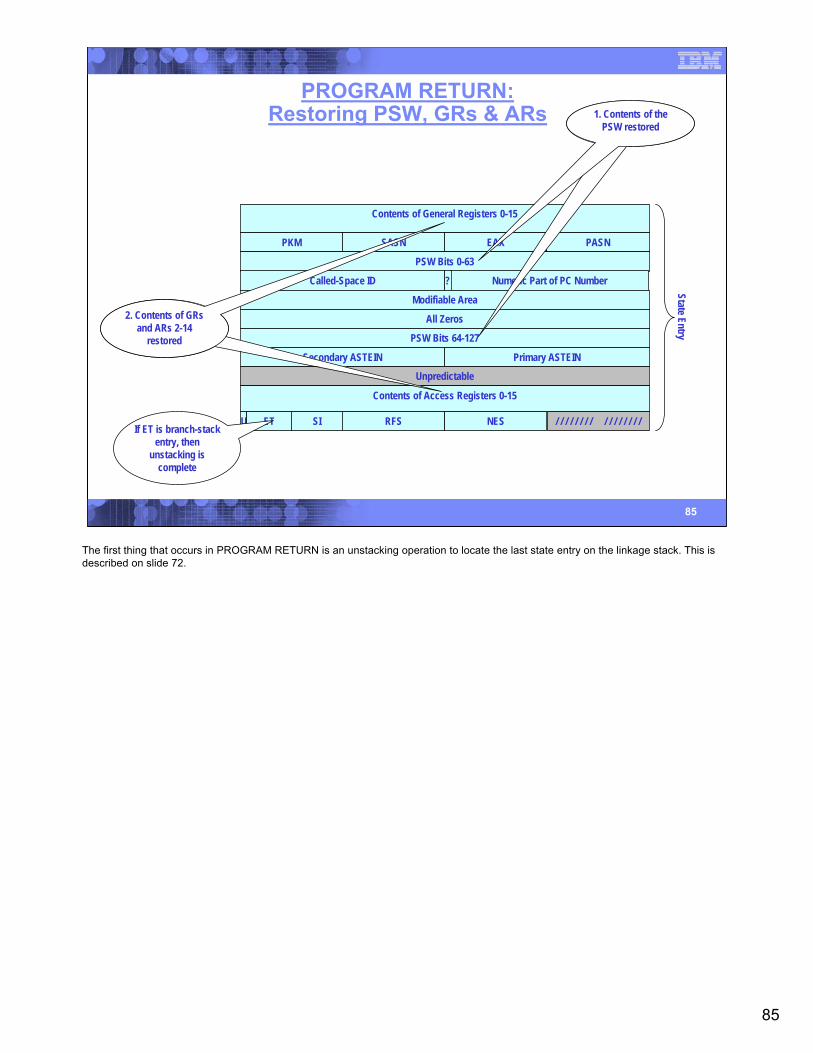
85
85
PROGRAM RETURN:Restoring PSW, GRs & ARs
Contents of General Registers 0-15
PKM SASN EAX PASN
PSW Bits 0-63
Called-Space ID Numeric Part of PC Number?
Modifiable Area
All Zeros
PSW Bits 64-127
Secondary ASTEIN Primary ASTEIN
Unpredictable
Contents of Access Registers 0-15
RFSU ET SI NES / / / / / / / / / / / / / / / /
State Entry1. Contents of the
PSW restored
2. Contents of GRsand ARs 2-14
restored
If ET is branch-stack entry, then
unstacking is complete
The first thing that occurs in PROGRAM RETURN is an unstacking operation to locate the last state entry on the linkage stack. This is described on slide 72.
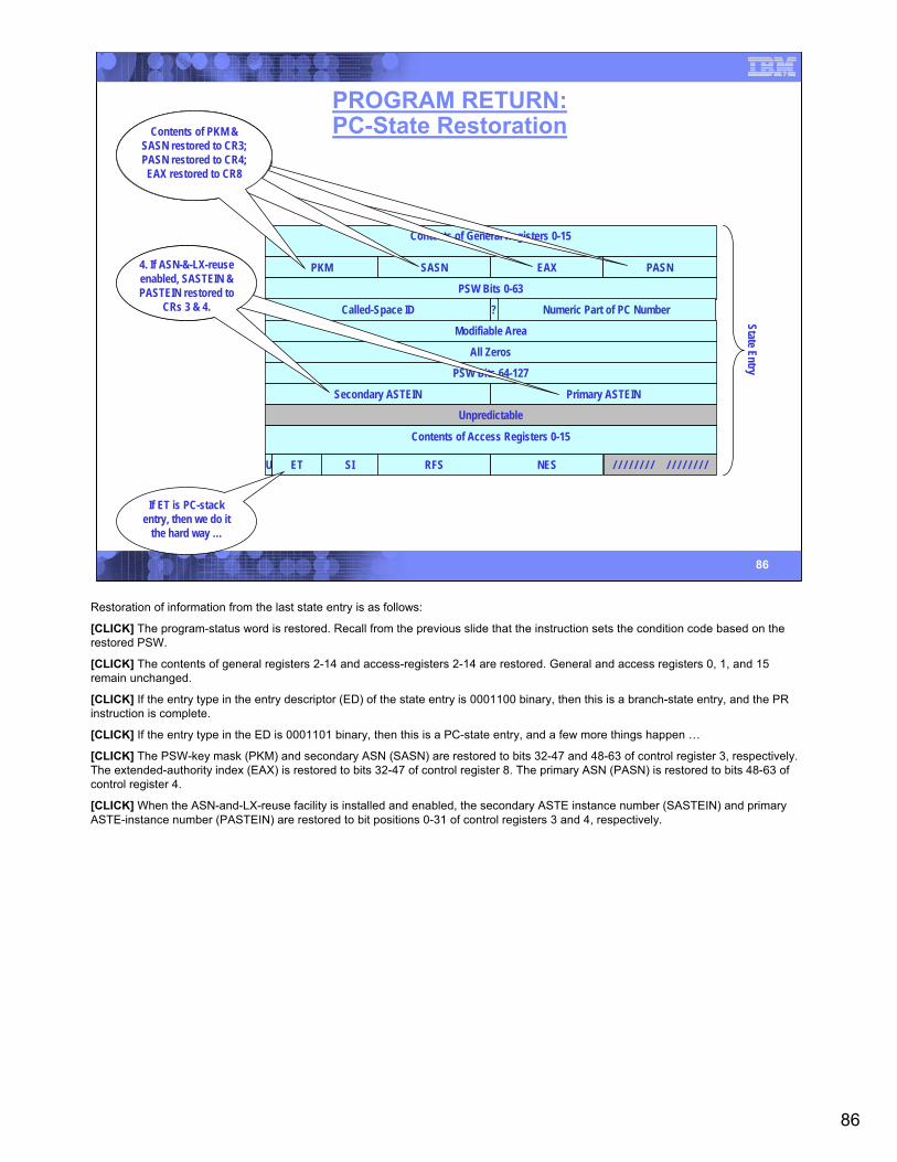
86
86
PROGRAM RETURN:PC-State Restoration
Contents of General Registers 0-15
PKM SASN EAX PASN
PSW Bits 0-63
Called-Space ID Numeric Part of PC Number?
Modifiable Area
All Zeros
PSW Bits 64-127
Secondary ASTEIN Primary ASTEIN
Unpredictable
Contents of Access Registers 0-15
RFSU ET SI NES / / / / / / / / / / / / / / / /
State Entry
4. If ASN-&-LX-reuse enabled, SASTEIN & PASTEIN restored to
CRs 3 & 4.
If ET is PC-stack entry, then we do it
the hard way …
Contents of PKM & SASN restored to CR3; PASN restored to CR4; EAX restored to CR8
Restoration of information from the last state entry is as follows:
[CLICK] The program-status word is restored. Recall from the previous slide that the instruction sets the condition code based on the restored PSW.
[CLICK] The contents of general registers 2-14 and access-registers 2-14 are restored. General and access registers 0, 1, and 15 remain unchanged.
[CLICK] If the entry type in the entry descriptor (ED) of the state entry is 0001100 binary, then this is a branch-state entry, and the PR instruction is complete.
[CLICK] If the entry type in the ED is 0001101 binary, then this is a PC-state entry, and a few more things happen …
[CLICK] The PSW-key mask (PKM) and secondary ASN (SASN) are restored to bits 32-47 and 48-63 of control register 3, respectively. The extended-authority index (EAX) is restored to bits 32-47 of control register 8. The primary ASN (PASN) is restored to bits 48-63 of control register 4.
[CLICK] When the ASN-and-LX-reuse facility is installed and enabled, the secondary ASTE instance number (SASTEIN) and primary ASTE-instance number (PASTEIN) are restored to bit positions 0-31 of control registers 3 and 4, respectively.
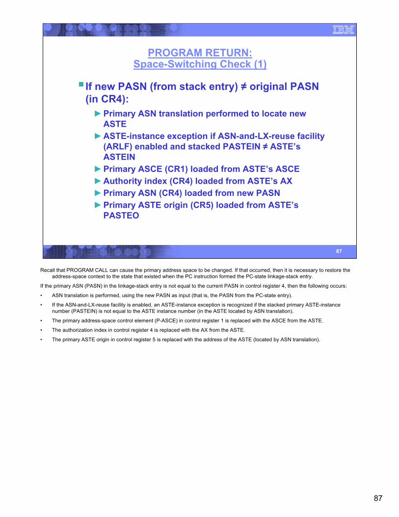
87
87
PROGRAM RETURN:Space-Switching Check (1)
If new PASN (from stack entry) ≠ original PASN (in CR4):►Primary ASN translation performed to locate new
ASTE►ASTE-instance exception if ASN-and-LX-reuse facility
(ARLF) enabled and stacked PASTEIN ≠ ASTE’sASTEIN
►Primary ASCE (CR1) loaded from ASTE’s ASCE►Authority index (CR4) loaded from ASTE’s AX►Primary ASN (CR4) loaded from new PASN►Primary ASTE origin (CR5) loaded from ASTE’s
PASTEO
Recall that PROGRAM CALL can cause the primary address space to be changed. If that occurred, then it is necessary to restore the address-space context to the state that existed when the PC instruction formed the PC-state linkage-stack entry.
If the primary ASN (PASN) in the linkage-stack entry is not equal to the current PASN in control register 4, then the following occurs:
• ASN translation is performed, using the new PASN as input (that is, the PASN from the PC-state entry).
• If the ASN-and-LX-reuse facility is enabled, an ASTE-instance exception is recognized if the stacked primary ASTE-instance number (PASTEIN) is not equal to the ASTE instance number (in the ASTE located by ASN translation).
• The primary address-space control element (P-ASCE) in control register 1 is replaced with the ASCE from the ASTE.
• The authorization index in control register 4 is replaced with the AX from the ASTE.
• The primary ASTE origin in control register 5 is replaced with the address of the ASTE (located by ASN translation).
88
88
PROGRAM RETURN:Space-Switching Check (2)
If stacked SASN = stacked PASN►Secondary ASTE (CR7) loaded from primary ASTE
(CR1)Else (stacked SASN ≠ stacked PASN)►Secondary ASN translation performed to locate new
ASTE►ASTE-instance exception if ASN-and-LX-reuse facility
(ARLF) enabled and stacked SASTEIN ≠ ASTE’sASTEIN
►Secondary ASCE (CR7) loaded from ASTE’s ASCE►SASN authorization performed:
– Secondary-authority exception if S bit (located from authority-table origin (ATO) in ASCE plus stacked AX) is zero
The previous slide dealt with the primary address space. Here we check whether the secondary address-space parameters need to be adjusted.
If the stacked secondary ASN (SASN) is equal to the stacked primary ASN (PASN), then we simply load the secondary ASCE (in control register 7) with the new contents of the primary ASCE (from control register 1).
Otherwise, when the stacked PASN and SASN differ, the following is performed.
• ASN translation is performed using the stacked SASN as input.
• If the ASN-and-LX-reuse facility is enabled, an ASTE-instance exception is recognized if the stacked SASTEIN is not equal to the ASTEIN in the ASTE (located by ASN translation).
• The secondary address-space control element (S-ASCE) in control register 7 is replaced with the ASCE from the ASTE.
One final step, and we’re through. The ASTE located in the ASN-translation process contains the origin to an authority table corresponding to that address space. If the new authorization index (AX, restored from the stack in the previous slide) designates a pair of P/S authority bits in which the S bit is zero, then a secondary-authority exception is recognized (PIC 0025 hex).
And that’s it for PROGRAM RETURN!
Whew!
89
89
zOS LS-Related Macros
IEALSQRY – Linkage-stack queryLSEXPAND – Expand linkage-stack capacityPCLINK – Stack, unstack, or extract PC linkage information
Note, z/OS maintains two linkage stacks:►Normal and recovery linkage stack
See MVS Programming: Authorized Assembler Services Reference (volumes 2-4),
MVS Programming: Assembler Service Reference (IAR-XCT), andMVS Programming: Extended Addressability Guide for details
z/OS macro instructions for the management of the linkage stack. This slide provides an inventory of some of these macro instructions.
For more details, please refer to the following documents:
• zOS MVS Programming: Authorized Assembler Services Reference, Volume 2 (EDT-IXG) [SA22-7610]
• zOS MVS Programming: Authorized Assembler Services Reference, Volume 3 (LLA-SDU) [SA22-7611]
• MVS Programming: Assembler Service Reference (IAR-XCT) [SA22-7606]
• zOS MVS Programming: Extended Addressability Guide [SA22-7614]
90
90
In Summary
S/360 & its progeny provide a legacy of powerful system-integrity features:
► Supervisor state, key-controlled protection; dynamic address translation
Dual-address-space extends these features with a highly structured means of program linkage & data movement across address spaces.
► Independent of – and preceding – AR-mode access
Linkage-stack extends the highly-structured program-linkage mechanisms
► Allows PC to increase or decrease authority as it calls other routines
► Provides program-accessible stack entry – minimizing or eliminating the need for save areas.
► Improves the RAS characteristics authorized or nonauthorized program services.
Congratulations! The last hour’s presentation contained an enormous amount of detail regarding an extremely complicated subject. Pat yourself on the back for having survived it!!
The architecture upon which the dual-address-space (DAS) function is built dates back to the original S/360. These architectural features are one of the distinguishing features of the S/360 and its follow-on series up processors, up to and including the current System Z machines. Features like supervisor state, storage-protection keys, and dynamic address translation.
The DAS features provide a very controlled means of calling programs in a separate address space, while retaining CPU-controlled limits on the accessability of such programs, based on structures provided by the control program.
The linkage stack extended the DAS features, increasing the flexibility of PROGRAM CALL and adding the BRANCH AND STACK mechanisms. All of these contribute to improved reliability, availability, and servicability (RAS) of the programs running under z/OS.
Although not discussed in this presentation, AR mode extended the addressability features of the program, and can be used in conjunction with, or independent of, DAS and the linkage stack to provide even greater flexibility in programming … all while retaining the classic reliability provided by the hardware and z/OS operating systems.
91
91
Questions?
For those in the live audience, I will gladly entertain questions here.
For those who view this on the SHARE web site, your questions are also welcome. My email address is listed on the first slide.