dual enclosure liquid cooling (delc)
TRANSCRIPT
© 2011 IBM Corporation
Dual Enclosure Liquid Cooling (DELC)Chiller-less Data Centers with Liquid Cooled Servers To Enable Significant Data Center Energy Savings
IBM Acknowledgements: Pok Site & Facilities/G&E (Donato Caferra, Sal Rosato, Joe Caricari, Tony “D”, Yun Lau, Chris), Pat Coico, James Steffes, Corey Vandeventer, Mark Steinke, Gerry Weber, Mike Ellsworth, James Whately, Brenda Horton, Yves Martin
Dr. Madhu Iyengar, Senior Engineer, STG Advanced Thermal LabDecember 13th 2011, Energy Efficiency HPC Working Group
Madhusudan Iyengar, Milnes David, Vinod Kamath, David Graybill, Bejoy Kochuparambil, Robert Simons and Roger Schmidt.IBM System and Technology Group (STG)
Timothy Chainer (PI), Michael Gaynes, Pritish Parida, Mark Schultz, Arun Sharma, and Hien Dang.IBM Research Division
© 2011 IBM CorporationIBM, December 13th 2011, Energy Efficiency HPC Working Group
This project was supported in part by the U.S. Department of Energy's Industrial Technologies Program under the American Recovery and Reinvestment Act of 2009, award no. DE-EE0002894. We thank the DOE Project Officer Debo Aichbhaumik, DOE Project Monitors Darin Toronjo and Chap Sapp and DOE HQ Contact Gideon Varga for their support throughout the project.
Acknowledgements
2
© 2011 IBM CorporationIBM, December 13th 2011, Energy Efficiency HPC Working Group
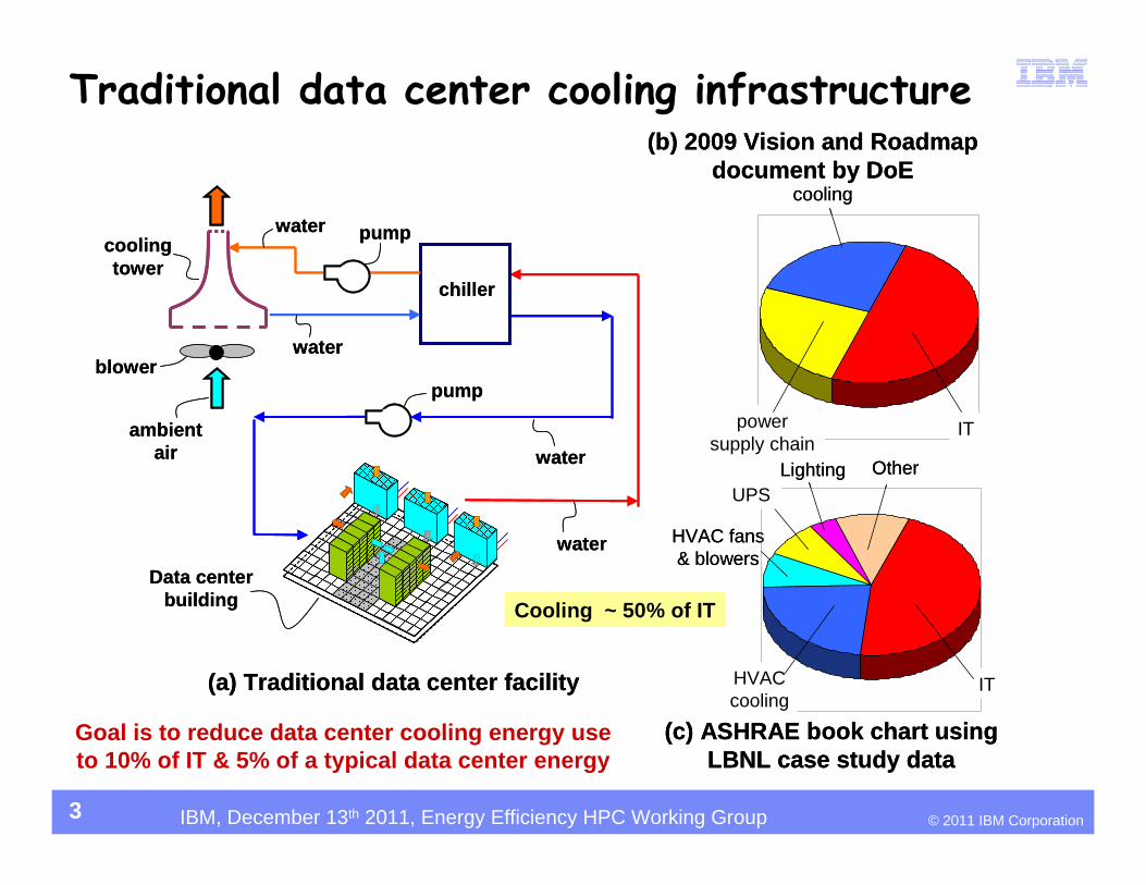
Goal is to reduce data center cooling energy use to 10% of IT & 5% of a typical data center energy
Traditional data center cooling infrastructure
3
pump
chiller
ambient air
cooling tower
blowerwater
water
water
water
pump
Data center building
(a) Traditional data center facility
Cooling ~ 50% of IT
ITpower supply chain
cooling
HVAC cooling
IT
Lighting
HVAC fans & blowers
UPSOther
(b) 2009 Vision and Roadmap document by DoE
(c) ASHRAE book chart using LBNL case study data
pump
chiller
ambient air
cooling tower
blowerwater
water
water
water
pump
Data center building
(a) Traditional data center facility
Cooling ~ 50% of IT
ITpower supply chain
cooling
HVAC cooling
IT
Lighting
HVAC fans & blowers
UPSOther
(b) 2009 Vision and Roadmap document by DoE
(c) ASHRAE book chart using LBNL case study data
© 2011 IBM CorporationIBM, December 13th 2011, Energy Efficiency HPC Working Group
P
liquid cooled cold plates
server rack enclosure
facility of rack location
electronics attached to cold plates, e.g. CPU
modules
electronics being air cooled
inside rack enclosure
air to liquid heat exchanger that
cools reticulating air in rack enclosure
heat load dissipated to
reticulating air
pump
air to liquid heat exchanger
fan
ambient air
exhaust air to
ambient
remote or local heat exchange enclosure
liquid piping
heat generating electronic equipment
heat load dissipated to
liquid
T1
T2T3
T6
T7 T9
T10
VFD
VFD
RPM2
RPM1
recirculation valve
Programmable Logic Control (PLC)Receiving data for
T1 T10, RPM1 RPM2 RPM3
Qw, Qa, F, etc.
P
RPM3VFD
T4 T5
T8
buffer heat exchanger and
pumping unit (WCU)
P
liquid cooled cold plates
server rack enclosure
facility of rack location
electronics attached to cold plates, e.g. CPU
modules
electronics being air cooled
inside rack enclosure
air to liquid heat exchanger that
cools reticulating air in rack enclosure
heat load dissipated to
reticulating air
pump
air to liquid heat exchanger
fan
ambient air
exhaust air to
ambient
remote or local heat exchange enclosure
liquid piping
heat generating electronic equipment
heat load dissipated to
liquid
T1
T2T3
T6
T7 T9
T10
VFD
VFD
RPM2
RPM1
recirculation valve
Programmable Logic Control (PLC)Receiving data for
T1 T10, RPM1 RPM2 RPM3
Qw, Qa, F, etc.
P
RPM3VFD
T4 T5
T8
buffer heat exchanger and
pumping unit (WCU)
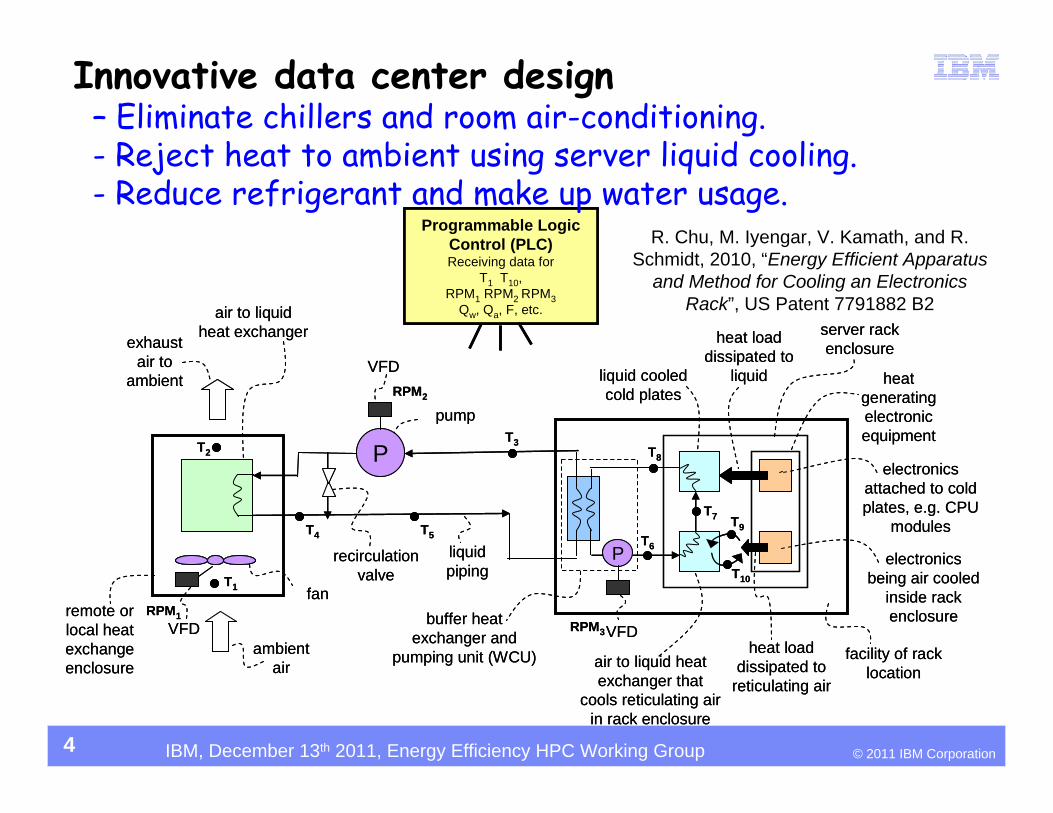
Innovative data center design – Eliminate chillers and room air-conditioning.- Reject heat to ambient using server liquid cooling.- Reduce refrigerant and make up water usage.
4
R. Chu, M. Iyengar, V. Kamath, and R. Schmidt, 2010, “Energy Efficient Apparatus
and Method for Cooling an Electronics Rack”, US Patent 7791882 B2
© 2011 IBM CorporationIBM, December 13th 2011, Energy Efficiency HPC Working Group
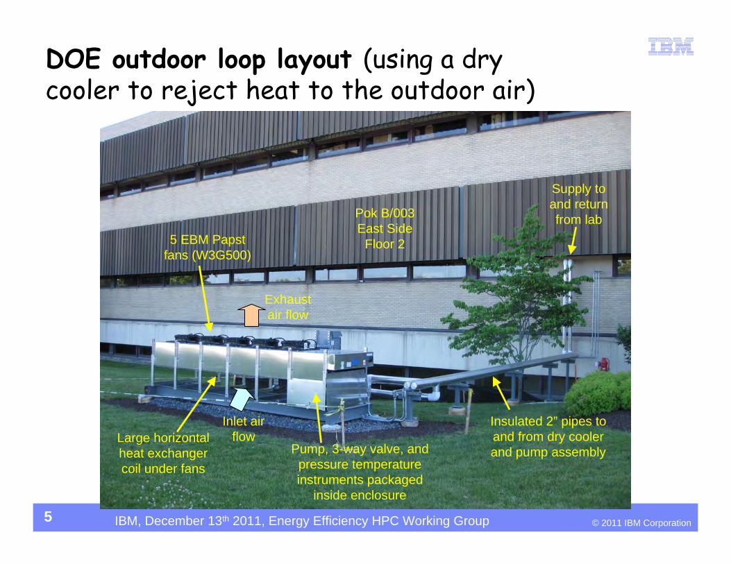
DOE outdoor loop layout (using a dry cooler to reject heat to the outdoor air)
Supply to and return from lab
Insulated 2” pipes to and from dry cooler and pump assembly
Large horizontal heat exchanger coil under fans
5 EBM Papst fans (W3G500)
Pump, 3-way valve, and pressure temperature instruments packaged
inside enclosure
Pok B/003 East Side
Floor 2
Exhaust air flow
Inlet air flow
5
© 2011 IBM CorporationIBM, December 13th 2011, Energy Efficiency HPC Working Group
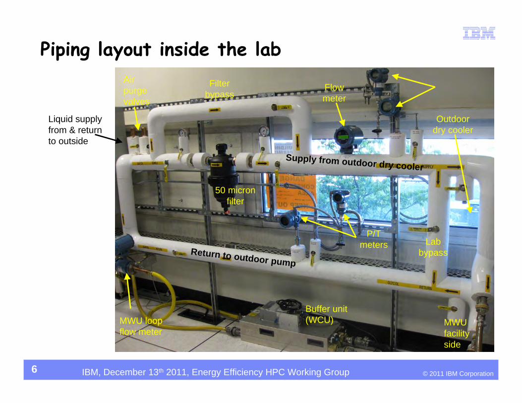
Piping layout inside the lab
Buffer unit (WCU)
Return to outdoor pump
Supply from outdoor dry cooler
50 micron filter
MWU facility side
Air purge valves
Outdoor dry cooler
P/T meters
Flow meter
Liquid supply from & return to outside
Lab bypass
Filter bypass
MWU loop flow meter
6
© 2011 IBM CorporationIBM, December 13th 2011, Energy Efficiency HPC Working Group
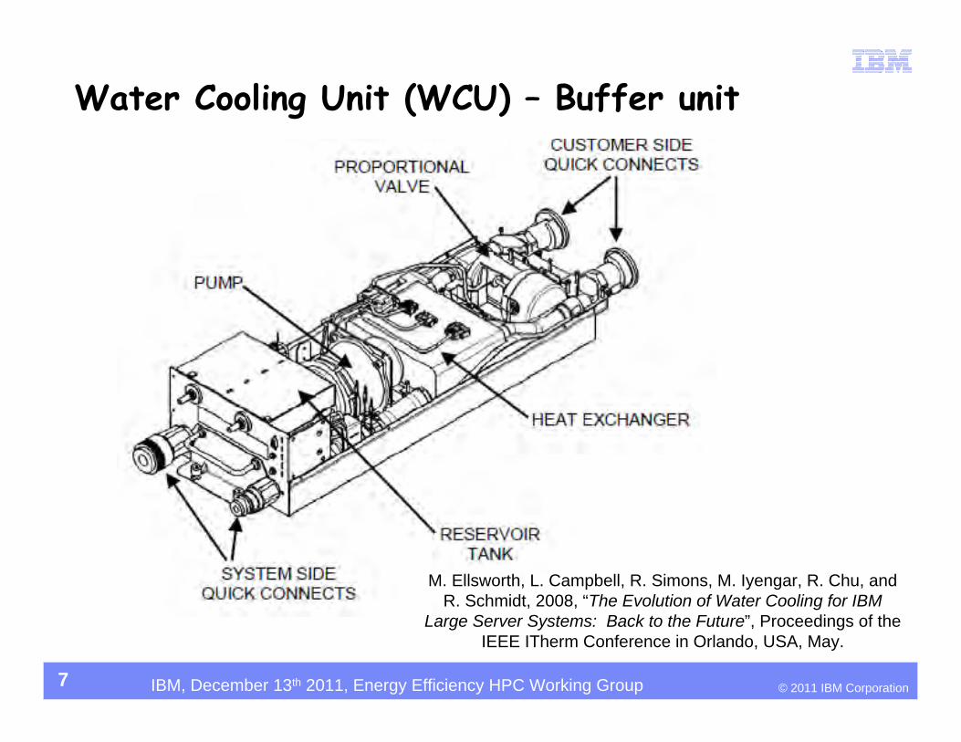
Water Cooling Unit (WCU) – Buffer unit
7
M. Ellsworth, L. Campbell, R. Simons, M. Iyengar, R. Chu, and R. Schmidt, 2008, “The Evolution of Water Cooling for IBM
Large Server Systems: Back to the Future”, Proceedings of the IEEE ITherm Conference in Orlando, USA, May.
© 2011 IBM CorporationIBM, December 13th 2011, Energy Efficiency HPC Working Group
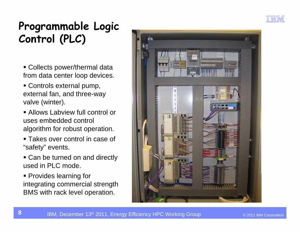
Programmable Logic Control (PLC)
Collects power/thermal data from data center loop devices. Controls external pump, external fan, and three-way valve (winter). Allows Labview full control or uses embedded control algorithm for robust operation. Takes over control in case of “safety” events. Can be turned on and directly used in PLC mode. Provides learning for integrating commercial strength BMS with rack level operation.
8
© 2011 IBM CorporationIBM, December 13th 2011, Energy Efficiency HPC Working Group
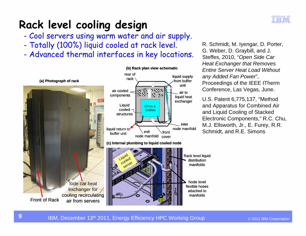
Front of Rack
Side car heat exchanger for
cooling recirculating air from servers
Liquid cooled
structures
CPUs &DIMMs
(b) Rack plan view schematic
front cover
rear of rack
air cooled components
liquid return to buffer unit
liquid supply from buffer
unit
air to liquid heat exchanger
inlet node manifold
exitnode manifold
(a) Photograph of rack
(c) Internal plumbing to liquid cooled node
Liquid
cooled
server
Rack level liquid distribution manifolds
Node level flexible hoses
attached to manifolds
Rack level cooling design- Cool servers using warm water and air supply.- Totally (100%) liquid cooled at rack level.- Advanced thermal interfaces in key locations.
9
R. Schmidt, M. Iyengar, D. Porter, G. Weber, D. Graybill, and J. Steffes, 2010, “Open Side Car Heat Exchanger that Removes Entire Server Heat Load Without any Added Fan Power”, Proceedings of the IEEE ITherm Conference, Las Vegas, June.
U.S. Patent 6,775,137, “Method and Apparatus for Combined Air and Liquid Cooling of Stacked Electronic Components,” R.C. Chu, M.J. Ellsworth, Jr., E. Furey, R.R. Schmidt, and R.E. Simons
© 2011 IBM CorporationIBM, December 13th 2011, Energy Efficiency HPC Working Group
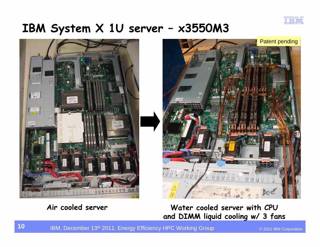
IBM System X 1U server – x3550M3
Air cooled server Water cooled server with CPU and DIMM liquid cooling w/ 3 fans
10
Patent pending
© 2011 IBM CorporationIBM, December 13th 2011, Energy Efficiency HPC Working Group
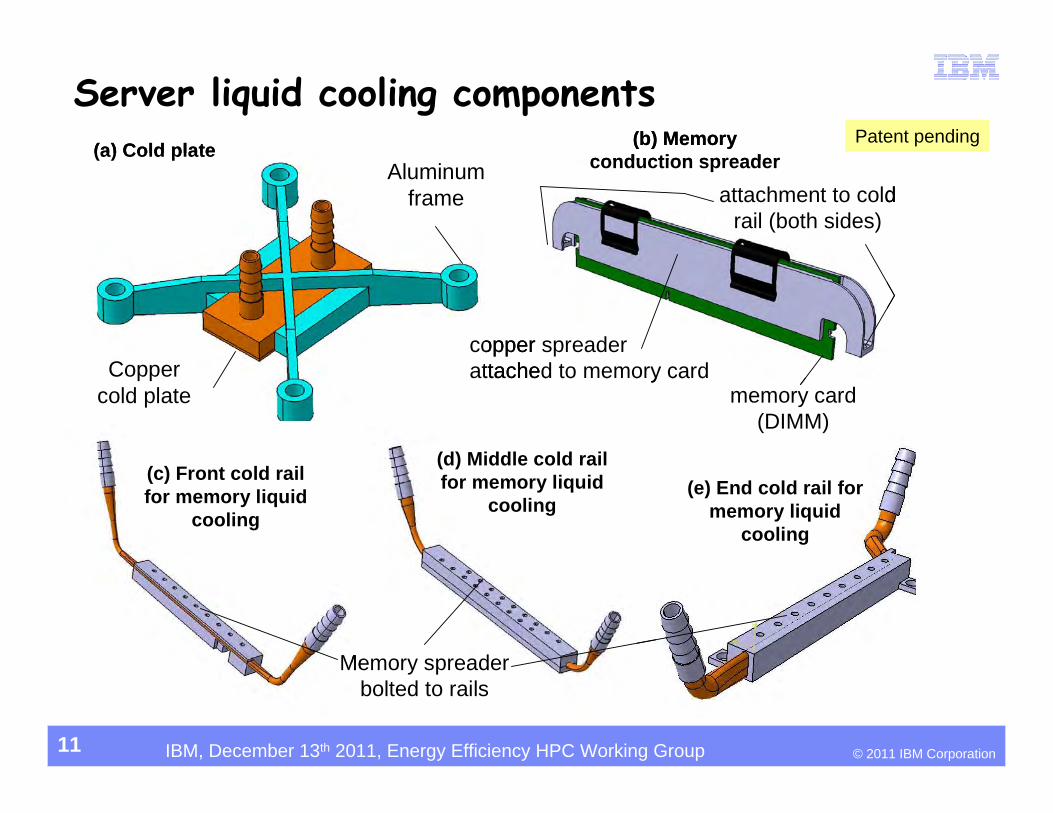
Aluminum frame
Copper cold plate
(c) Front cold rail for memory liquid
cooling
(d) Middle cold rail for memory liquid
cooling(e) End cold rail for
memory liquid cooling
(a) Cold plate (b) Memory conduction spreader
copper spreader attached to memory card
Memory spreader bolted to rails
memory card (DIMM)
attachment to cold rail (both sides)
Server liquid cooling components
11
Patent pending
© 2011 IBM CorporationIBM, December 13th 2011, Energy Efficiency HPC Working Group
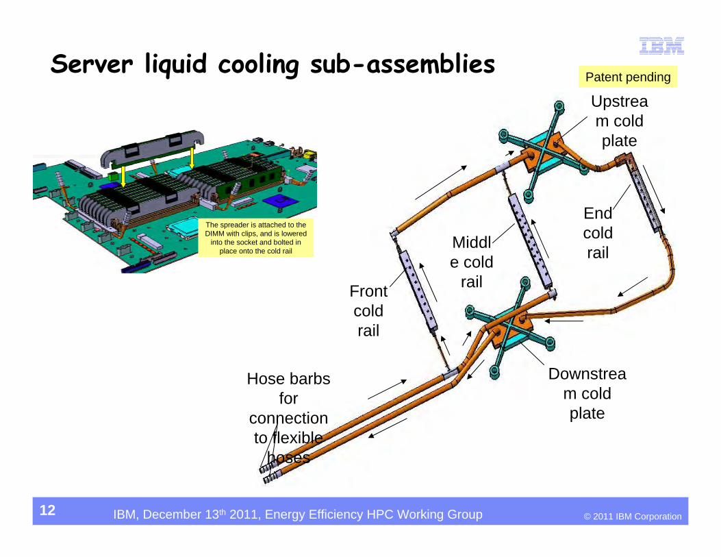
Front cold rail
End cold railMiddl
e cold rail
Upstream cold plate
Downstream cold plate
Hose barbs for
connection to flexible
hoses
The spreader is attached to the DIMM with clips, and is lowered
into the socket and bolted in place onto the cold rail
Server liquid cooling sub-assemblies
12
Patent pending
© 2011 IBM CorporationIBM, December 13th 2011, Energy Efficiency HPC Working Group
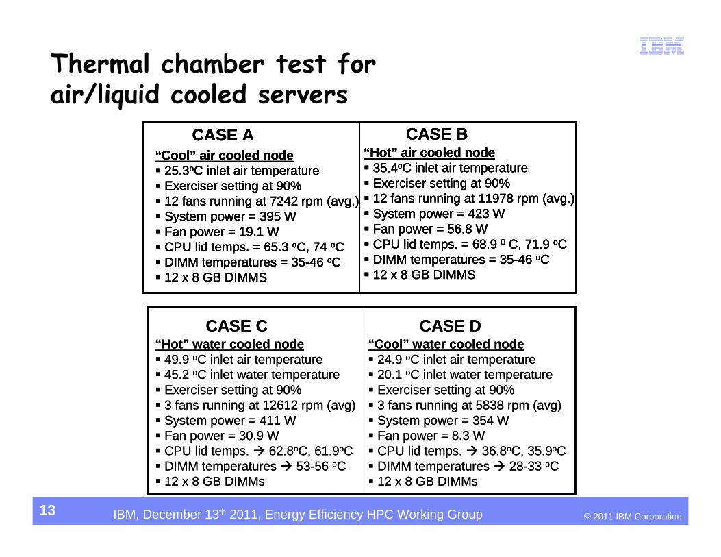
“Cool” air cooled node 25.3oC inlet air temperature Exerciser setting at 90% 12 fans running at 7242 rpm (avg.) System power = 395 W Fan power = 19.1 W CPU lid temps. = 65.3 oC, 74 oC DIMM temperatures = 35-46 oC 12 x 8 GB DIMMS
CASE A CASE B“Hot” air cooled node 35.4oC inlet air temperature Exerciser setting at 90% 12 fans running at 11978 rpm (avg.) System power = 423 W Fan power = 56.8 W CPU lid temps. = 68.9 0 C, 71.9 oC DIMM temperatures = 35-46 oC 12 x 8 GB DIMMS
“Hot” air cooled node 35.4oC inlet air temperature Exerciser setting at 90% 12 fans running at 11978 rpm (avg.) System power = 423 W Fan power = 56.8 W CPU lid temps. = 68.9 0 C, 71.9 oC DIMM temperatures = 35-46 oC 12 x 8 GB DIMMS
“Cool” air cooled node 25.3oC inlet air temperature Exerciser setting at 90% 12 fans running at 7242 rpm (avg.) System power = 395 W Fan power = 19.1 W CPU lid temps. = 65.3 oC, 74 oC DIMM temperatures = 35-46 oC 12 x 8 GB DIMMS
“Cool” air cooled node 25.3oC inlet air temperature Exerciser setting at 90% 12 fans running at 7242 rpm (avg.) System power = 395 W Fan power = 19.1 W CPU lid temps. = 65.3 oC, 74 oC DIMM temperatures = 35-46 oC 12 x 8 GB DIMMS
CASE A CASE B“Hot” air cooled node 35.4oC inlet air temperature Exerciser setting at 90% 12 fans running at 11978 rpm (avg.) System power = 423 W Fan power = 56.8 W CPU lid temps. = 68.9 0 C, 71.9 oC DIMM temperatures = 35-46 oC 12 x 8 GB DIMMS
“Hot” water cooled node 49.9 oC inlet air temperature 45.2 oC inlet water temperature Exerciser setting at 90% 3 fans running at 12612 rpm (avg) System power = 411 W Fan power = 30.9 W CPU lid temps. 62.8oC, 61.9oC DIMM temperatures 53-56 oC 12 x 8 GB DIMMs
“Cool” water cooled node 24.9 oC inlet air temperature 20.1 oC inlet water temperature Exerciser setting at 90% 3 fans running at 5838 rpm (avg) System power = 354 W Fan power = 8.3 W CPU lid temps. 36.8oC, 35.9oC DIMM temperatures 28-33 oC 12 x 8 GB DIMMs
CASE C CASE D“Hot” water cooled node 49.9 oC inlet air temperature 45.2 oC inlet water temperature Exerciser setting at 90% 3 fans running at 12612 rpm (avg) System power = 411 W Fan power = 30.9 W CPU lid temps. 62.8oC, 61.9oC DIMM temperatures 53-56 oC 12 x 8 GB DIMMs
“Cool” water cooled node 24.9 oC inlet air temperature 20.1 oC inlet water temperature Exerciser setting at 90% 3 fans running at 5838 rpm (avg) System power = 354 W Fan power = 8.3 W CPU lid temps. 36.8oC, 35.9oC DIMM temperatures 28-33 oC 12 x 8 GB DIMMs
CASE C CASE D
Thermal chamber test for air/liquid cooled servers
13
© 2011 IBM CorporationIBM, December 13th 2011, Energy Efficiency HPC Working Group
02468
1012141618
-30
to -2
5.1
-25
to -2
0.1
-20
to -1
5.1
-15
to -1
0.1
-10
to -5
.1
-5 to
-0.1
0 to
4.9
5 to
9.9
10 to
14.
9
15 to
19.
9
20 to
24.
9
25 to
29.
9
30 to
34.
9
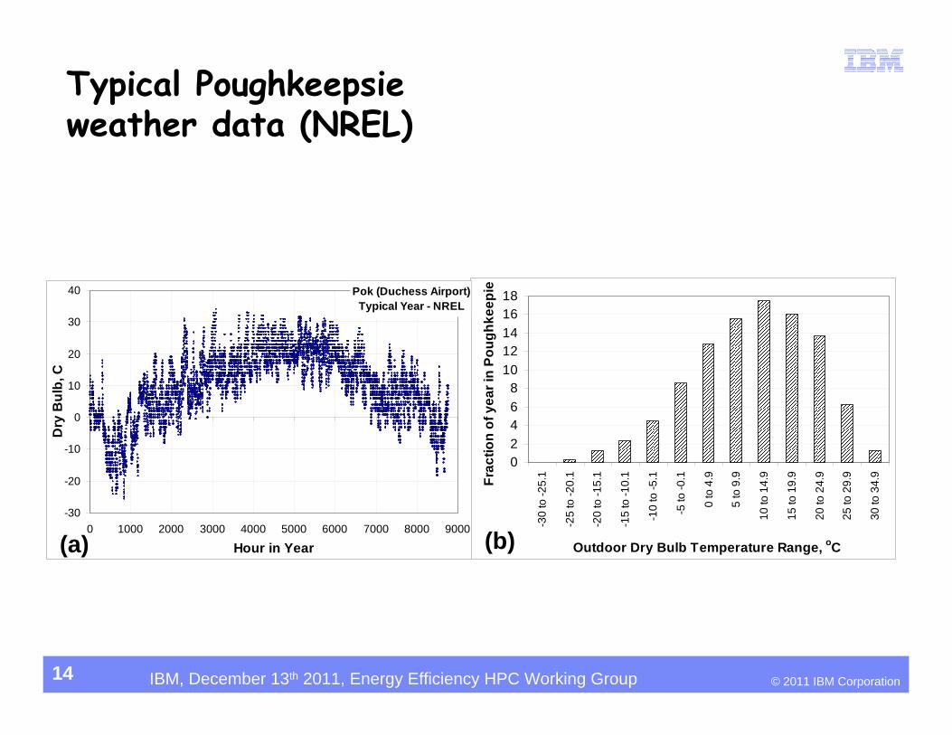
Outdoor Dry Bulb Temperature Range, oC
Frac
tion
of y
ear i
n Po
ughk
eepi
ePok (Duchess Airport)Typical Year - NREL
-30
-20
-10
0
10
20
30
40
0 1000 2000 3000 4000 5000 6000 7000 8000 9000
Hour in Year
Dry
Bul
b, C
(a) (b)
Typical Poughkeepsie weather data (NREL)
14
© 2011 IBM CorporationIBM, December 13th 2011, Energy Efficiency HPC Working Group
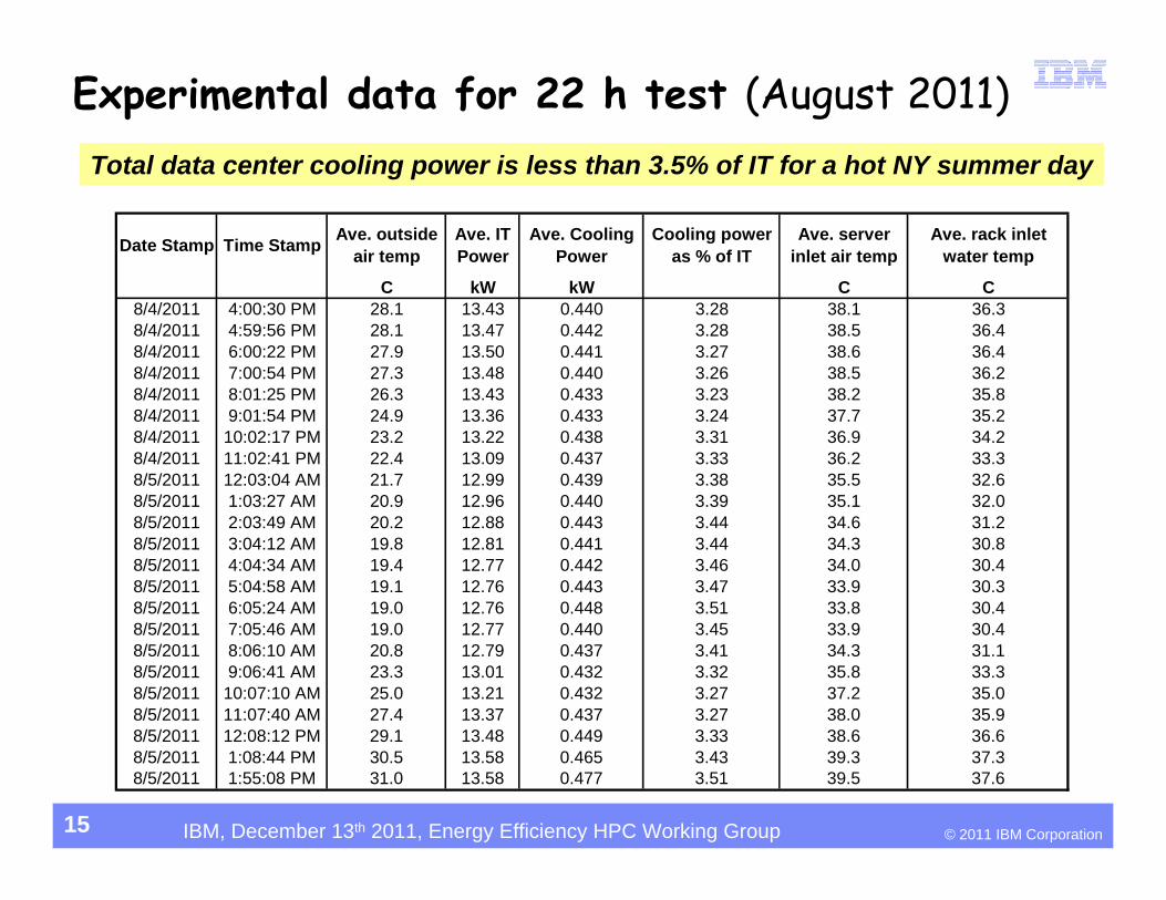
Date Stamp Time Stamp Ave. outside air temp
Ave. IT Power
Ave. Cooling Power
Cooling power as % of IT
Ave. server inlet air temp
Ave. rack inlet water temp
C kW kW C C8/4/2011 4:00:30 PM 28.1 13.43 0.440 3.28 38.1 36.38/4/2011 4:59:56 PM 28.1 13.47 0.442 3.28 38.5 36.48/4/2011 6:00:22 PM 27.9 13.50 0.441 3.27 38.6 36.48/4/2011 7:00:54 PM 27.3 13.48 0.440 3.26 38.5 36.28/4/2011 8:01:25 PM 26.3 13.43 0.433 3.23 38.2 35.88/4/2011 9:01:54 PM 24.9 13.36 0.433 3.24 37.7 35.28/4/2011 10:02:17 PM 23.2 13.22 0.438 3.31 36.9 34.28/4/2011 11:02:41 PM 22.4 13.09 0.437 3.33 36.2 33.38/5/2011 12:03:04 AM 21.7 12.99 0.439 3.38 35.5 32.68/5/2011 1:03:27 AM 20.9 12.96 0.440 3.39 35.1 32.08/5/2011 2:03:49 AM 20.2 12.88 0.443 3.44 34.6 31.28/5/2011 3:04:12 AM 19.8 12.81 0.441 3.44 34.3 30.88/5/2011 4:04:34 AM 19.4 12.77 0.442 3.46 34.0 30.48/5/2011 5:04:58 AM 19.1 12.76 0.443 3.47 33.9 30.38/5/2011 6:05:24 AM 19.0 12.76 0.448 3.51 33.8 30.48/5/2011 7:05:46 AM 19.0 12.77 0.440 3.45 33.9 30.48/5/2011 8:06:10 AM 20.8 12.79 0.437 3.41 34.3 31.18/5/2011 9:06:41 AM 23.3 13.01 0.432 3.32 35.8 33.38/5/2011 10:07:10 AM 25.0 13.21 0.432 3.27 37.2 35.08/5/2011 11:07:40 AM 27.4 13.37 0.437 3.27 38.0 35.98/5/2011 12:08:12 PM 29.1 13.48 0.449 3.33 38.6 36.68/5/2011 1:08:44 PM 30.5 13.58 0.465 3.43 39.3 37.38/5/2011 1:55:08 PM 31.0 13.58 0.477 3.51 39.5 37.6
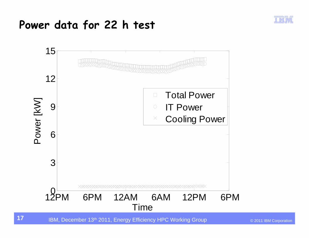
Experimental data for 22 h test (August 2011)Total data center cooling power is less than 3.5% of IT for a hot NY summer day
15
© 2011 IBM CorporationIBM, December 13th 2011, Energy Efficiency HPC Working Group
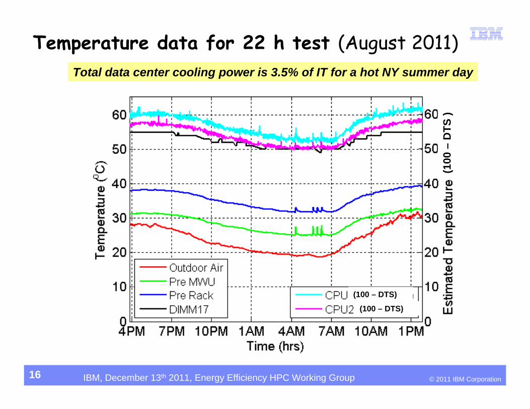
Temperature data for 22 h test (August 2011)Total data center cooling power is 3.5% of IT for a hot NY summer day
16
(100 – DTS)
(100 – DTS)
(100
–D
TS )
© 2011 IBM CorporationIBM, December 13th 2011, Energy Efficiency HPC Working Group
12PM 6PM 12AM 6AM 12PM 6PM0
3
6
9
12
15
Time
Pow
er [k
W]
Total PowerIT PowerCooling Power
Power data for 22 h test
17
© 2011 IBM CorporationIBM, December 13th 2011, Energy Efficiency HPC Working Group
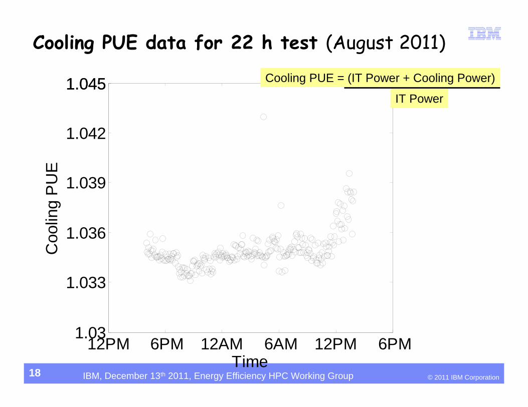
12PM 6PM 12AM 6AM 12PM 6PM1.03
1.033
1.036
1.039
1.042
1.0451.045
Time
Coo
ling
PU
ECooling PUE data for 22 h test (August 2011)
Cooling PUE = (IT Power + Cooling Power)
IT Power
18
© 2011 IBM CorporationIBM, December 13th 2011, Energy Efficiency HPC Working Group
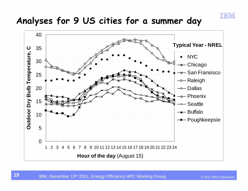
Analyses for 9 US cities for a summer day
19
Typical Year - NREL
0
5
10
15
20
25
30
35
40
1 2 3 4 5 6 7 8 9 10 11 12 13 14 15 16 17 18 19 20 21 22 23 24
Hour of the day (August 15)
Out
door
Dry
Bul
b Te
mpe
ratu
re, C
NYCChicagoSan FransiscoRaleighDallasPhoenixSeattleBuffaloPoughkeepsie
© 2011 IBM CorporationIBM, December 13th 2011, Energy Efficiency HPC Working Group
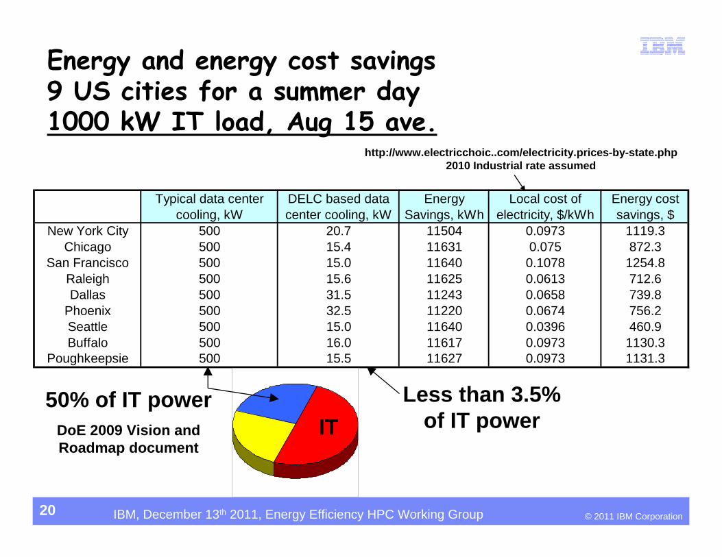
Energy and energy cost savings9 US cities for a summer day1000 kW IT load, Aug 15 ave.
20
Typical data center cooling, kW
DELC based data center cooling, kW
Energy Savings, kWh
Local cost of electricity, $/kWh
Energy cost savings, $
New York City 500 20.7 11504 0.0973 1119.3Chicago 500 15.4 11631 0.075 872.3
San Francisco 500 15.0 11640 0.1078 1254.8Raleigh 500 15.6 11625 0.0613 712.6Dallas 500 31.5 11243 0.0658 739.8
Phoenix 500 32.5 11220 0.0674 756.2Seattle 500 15.0 11640 0.0396 460.9Buffalo 500 16.0 11617 0.0973 1130.3
Poughkeepsie 500 15.5 11627 0.0973 1131.3
50% of IT powerDoE 2009 Vision and Roadmap document
Less than 3.5% of IT power
http://www.electricchoic..com/electricity.prices-by-state.php2010 Industrial rate assumed
IT
© 2011 IBM CorporationIBM, December 13th 2011, Energy Efficiency HPC Working Group
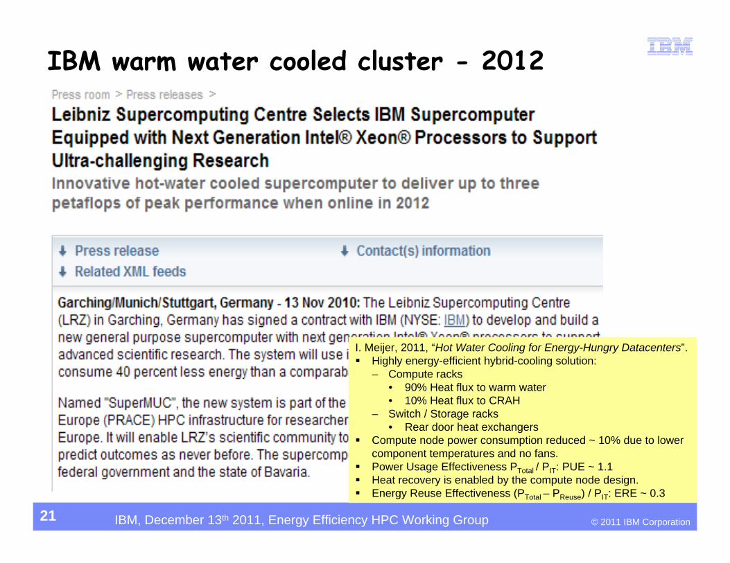
IBM warm water cooled cluster - 2012
21
I. Meijer, 2011, “Hot Water Cooling for Energy-Hungry Datacenters”. Highly energy-efficient hybrid-cooling solution:
– Compute racks • 90% Heat flux to warm water• 10% Heat flux to CRAH
– Switch / Storage racks• Rear door heat exchangers
Compute node power consumption reduced ~ 10% due to lower component temperatures and no fans.
Power Usage Effectiveness PTotal / PIT: PUE ~ 1.1 Heat recovery is enabled by the compute node design. Energy Reuse Effectiveness (PTotal – PReuse) / PIT: ERE ~ 0.3
© 2011 IBM CorporationIBM, December 13th 2011, Energy Efficiency HPC Working Group
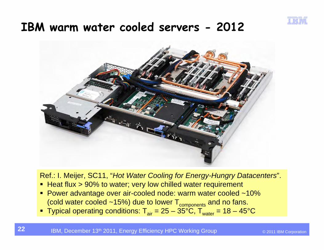
IBM warm water cooled servers - 2012
22
Ref.: I. Meijer, SC11, “Hot Water Cooling for Energy-Hungry Datacenters”. Heat flux > 90% to water; very low chilled water requirement Power advantage over air-cooled node: warm water cooled ~10%
(cold water cooled ~15%) due to lower Tcomponents and no fans. Typical operating conditions: Tair = 25 – 35°C, Twater = 18 – 45°C

© 2011 IBM CorporationIBM, December 13th 2011, Energy Efficiency HPC Working Group
Thank you
Q&AMadhu Iyengar
845-433-3708
23