dutton paper
DESCRIPTION
okTRANSCRIPT
�Slope Stability Santiago Chile, November 2009
Deep seated low wall deformation at Tutupan Coal Mine
The Tutupan Coal Mine, located in South Kalimantan (Borneo, Indonesia), is one of the largest coal open pits in the world, with an annual production of 45 Million tonnes. The proposed final pit is 18 kilometres long and up to 400 m deep. The open pit is developing a multi-seam deposit with coal seams up to 50 m thick and dipping from 20° to 70°. Interburden and overburden materials are soft rocks, mainly mudstone and weakly cemented sandstone. Low shear strength bedding parallel sheared zones are present throughout the deposit, particularly at coal-carbonaceous mudstone interfaces.A combination of low strength and stiffness rock, steep bedding dips and the complex distribution of the pore water pressure has resulted in the development of deep seated deformation in parts of the low wall. The deformation covers an area over 1 km long and 200 m high and has produced tension cracks in and behind the low wall with internal shearing surfaces daylighting in the mid slope. Inclinometers indicate the deformation zone extends more than 100 m below the low wall and there are several discrete planes of movement due to internal shearing within the potential failure mass. Robotic theodolites are being used to monitor low wall displacement with up to 1 m of movement per month whilst mining near the toe of the low wall.Numerical analyses have been undertaken to simulate the behaviour of the current pit and the proposed final pit using UDEC (Universal Distinct Element Code, Itasca). This modelling, in combination with the slope monitoring data is being used to understand the low wall deformation, determine whether this deep seated movement will lead to overall slope failure and to optimise the final pit slope angles.The paper describes the deposit geology, geotechnical and hydrogeological investigations, and the outcome from numerical modelling.
Abstract
Anthony Dutton, Cecile Coll and
David Nolan
Golder Associates
Joseph Crisostomo
PT Adaro Indonesia
INTRODUCTION
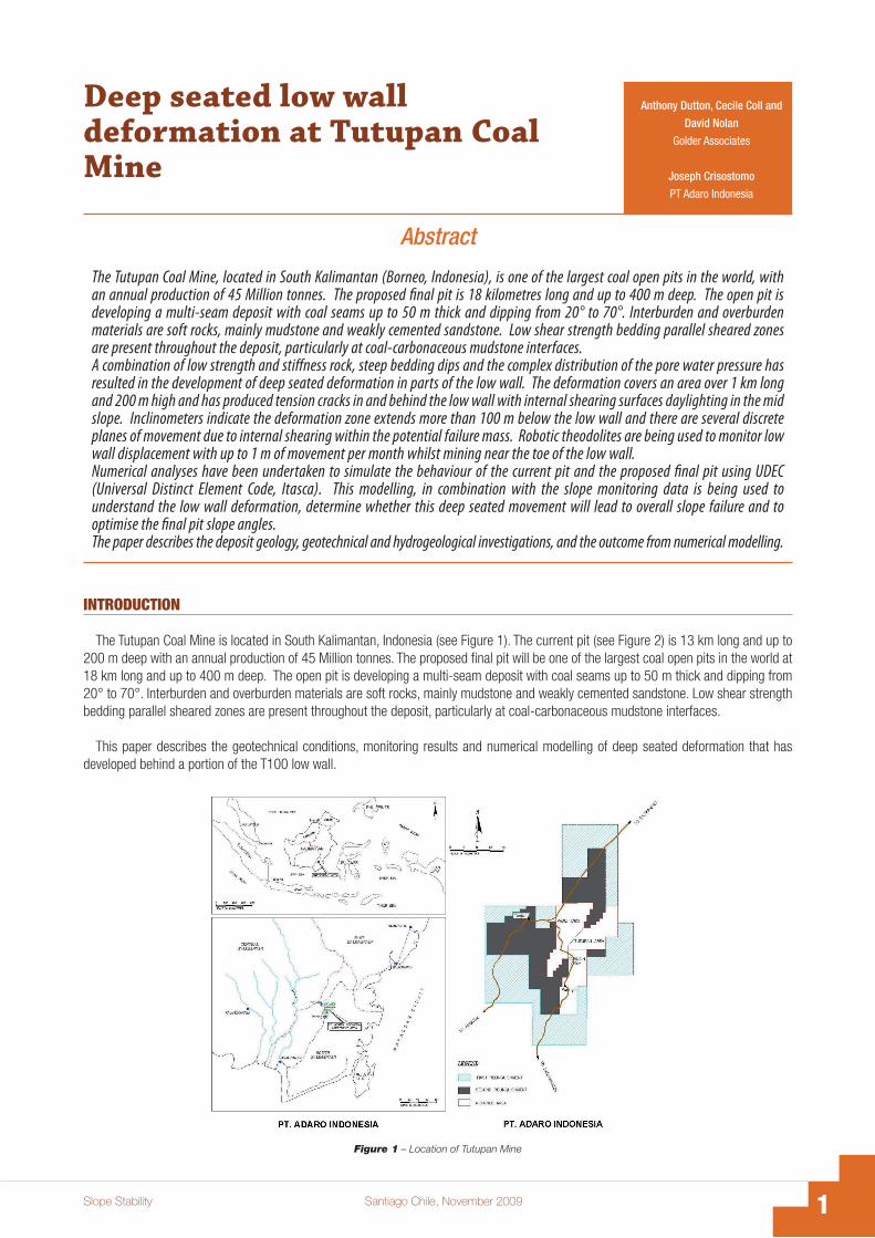
The Tutupan Coal Mine is located in South Kalimantan, Indonesia (see Figure 1). The current pit (see Figure 2) is 13 km long and up to 200 m deep with an annual production of 45 Million tonnes. The proposed final pit will be one of the largest coal open pits in the world at 18 km long and up to 400 m deep. The open pit is developing a multi-seam deposit with coal seams up to 50 m thick and dipping from 20° to 70°. Interburden and overburden materials are soft rocks, mainly mudstone and weakly cemented sandstone. Low shear strength bedding parallel sheared zones are present throughout the deposit, particularly at coal-carbonaceous mudstone interfaces.
This paper describes the geotechnical conditions, monitoring results and numerical modelling of deep seated deformation that has developed behind a portion of the T100 low wall.
Figure 1 – Location of Tutupan Mine

� Santiago Chile, November 2009 Slope Stability
Figure 2 – Site Plan
GEOLOGICAL SETTING
The pit is excavated in the Warukin Formation dated from the middle Miocene (Tertiary Age). The deposit consists of multiple coal seams up to 50 m thick separated by mudstone and sandstone interburden. The interburden above the T100 seam (one of the largest seam, Figure 2) is mudstone rich whilst the interburden immediately below the T100 seam is sandstone rich.
A combination of regional thrust faulting (not exposed in the pit) and folding has resulted in a large variation in bedding dip from 20° to 70° along the strike of the mine. Some low persistence normal (growth) faults have been encountered in the pit but have not affected wall stability to date.
Bedding ShearsNumerous low shear strength bedding parallel sheared zones (referred to hereafter as bedding shears) are present throughout the
deposit. Bedding shears can range from a clean slickensided contact to a fissile highly sheared zone up to 1000 mm thick. They have persistence of hundreds of metres and can change thickness and character along strike and down dip. Bedding shears are particularly prevalent at coal - mudstone interfaces and in isolated carbonaceous mudstone beds. The bedding shears are mostly composed of sheared mudstone or clay and occasionally composed of pulverised coal. Bedding shears have not been observed in the sandstone. Figure 3 illustrates a typical bedding shear along the floor of a coal seam.
Figure 3 – Typical Bedding

�Slope Stability Santiago Chile, November 2009
CoalThe coal is very blocky due to bedding partings and two sets of persistent cleat spaced 10 mm to 100 mm apart (see Figure 3). The
bedding partings and cleat are often highly polished or slickensided. Bedding shears and faults pulverise the coal where they pass through the seam.
MudstoneThe mudstone can be described as a soft rock or hard clay, composed of non-swelling kaolinite and silica. The mudstone is carbonaceous
in places, particularly in the immediate roof and floor of the coal seams. The mudstone contains irregularly oriented and closely spaced short persistence joints that form polygonal blocks typically 50 mm to 200 mm across. These joints are often slickensided, particularly adjacent to bedding shears.
SandstoneThe sandstone can be described as weakly cemented sandstone grading to very dense sand in places. It can often be broken down to
its constituent sand grains by hand. The sandstone often contains up to several joint sets but can be unbroken in places. Typical block sizes range from 100 mm to 2000 mm across. The joints surfaces are mostly undulating and rough.
HydrogeologyThe Tutupan mine is developed through a sequence of coal-bearing sedimentary rocks that includes fine-grained sandstone aquifers
and mudstone aquitards. Most of the mine is below the water table. The coal seams themselves do not form aquifers but drain freely where exposed in mine slopes. The aquifers are exposed at surface and are recharged seasonally by infiltration of rain, causing the water table to fluctuate annually by approximately 1-2 m. Slope dewatering and depressurisation has been achieved using free-flowing drainholes supplemented recently by pumped dewatering wells.
Extensive experience in managing groundwater pressures in both the low walls and the high walls has shown that the sandstone aquifers have excellent hydraulic continuity along strike. However, the mudstones act to prevent drainage across bedding from one sandstone unit to another. Critical to slope design is the extent to which the low permeability mudstone units can be depressurised. The current understanding is that thinner mudstones (up to about 20 m) depressurise within weeks of dewatering of the adjacent sandstones but that thicker mudstone pressures are depressurised mostly by unloading effects when overlying material is mined.
INTACT ROCK STRENGTH
An ongoing suite of uniaxial compression, triaxial compression and direct shear laboratory tests have been undertaken to determine the strength of the intact material. Unfortunately the triaxial compression and direct shear tests done to date have been run too fast by the laboratories to dissipate the excess pore pressure and no useable results have been obtained for the low permeability mudstones. The estimates of intact strength have thus relied upon the uniaxial compression tests. Typical values for the Uniaxial Compressive Strength (UCS), density and Young’s Modulus (E) are summarised in Table I.
MaterialUCS
(MPa)Density(kg/m3)
E(MPa)
Coal 6 [0.2 – 22] 1260 [1230 – 1300] 620 [80 – 1100]
Mudstone * 3 [0.1 – 17] 2350 [1960 – 2490] 180 [2 – 1500]
Sandstone 2 [0.1 – 16] 2200 [2000 – 2360] 110 [4 – 650]
Table I – Typical Intact Material Properties.
Some of the mudstone strengths and stiffnesses may have been over estimated due to moisture loss from the samples prior to testing. In some cases it has been difficult to select samples that are devoid of partly healed slickensided surfaces.
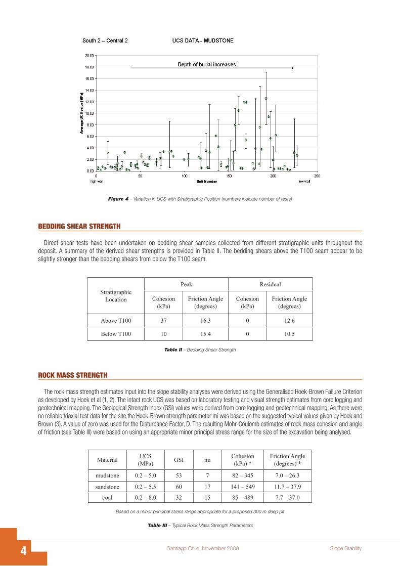
There is considerable variability in intact properties throughout the deposit both within individual stratigraphic units and comparing different stratigraphic units of similar materials. There are no consistent mine wide trends of strength change along strike or down dip within an individual stratigraphic unit. Rather the strength variation appears to be random with some localised clumping of higher or lower strength. The only notable trend is an increase in density, stiffness and strength of the mudstones with position in the stratigraphic column (depth of burial) (Figure 4).
� Santiago Chile, November 2009 Slope Stability
BEDDING SHEAR STRENGTH
Direct shear tests have been undertaken on bedding shear samples collected from different stratigraphic units throughout the deposit. A summary of the derived shear strengths is provided in Table II. The bedding shears above the T100 seam appear to be slightly stronger than the bedding shears from below the T100 seam.
Figure 4 – Variation in UCS with Stratigraphic Position (numbers indicate number of tests)
StratigraphicLocation
Peak Residual
Cohesion(kPa)
Friction Angle(degrees)
Cohesion(kPa)
Friction Angle(degrees)
Above T100 37 16.3 0 12.6
Below T100 10 15.4 0 10.5
Table II – Bedding Shear Strength
ROCK MASS STRENGTH
The rock mass strength estimates input into the slope stability analyses were derived using the Generalised Hoek-Brown Failure Criterion as developed by Hoek et al (1, 2). The intact rock UCS was based on laboratory testing and visual strength estimates from core logging and geotechnical mapping. The Geological Strength Index (GSI) values were derived from core logging and geotechnical mapping. As there were no reliable triaxial test data for the site the Hoek-Brown strength parameter mi was based on the suggested typical values given by Hoek and Brown (3). A value of zero was used for the Disturbance Factor, D. The resulting Mohr-Coulomb estimates of rock mass cohesion and angle of friction (see Table III) were based on using an appropriate minor principal stress range for the size of the excavation being analysed.
MaterialUCS
(MPa)GSI mi
Cohesion(kPa) *
Friction Angle(degrees) *
mudstone 0.2 – 5.0 53 7 82 – 345 7.0 – 26.3
sandstone 0.2 – 5.5 60 17 141 – 549 11.7 – 37.9
coal 0.2 – 8.0 32 15 85 – 489 7.7 – 37.0
Table III – Typical Rock Mass Strength Parameters
Based on a minor principal stress range appropriate for a proposed 300 m deep pit

�Slope Stability Santiago Chile, November 2009
It is recognised that the applied approach was not derived for application to “soft rocks” and consequently the above strength estimates need to be treated with caution. This approach was adopted out of necessity rather than choice. The authors are not aware of any well developed rock mass strength estimation techniques that have been specifically derived for soft rocks. Despite these potential limitations, the rock mass strength estimates derived using this approach are in reasonable agreement with the strengths obtained from back analysis of batter scale failures recorded in the pit when accounting for the likely stress range that the failures occurred in.
As there are no consistent trends, within a stratigraphic unit relative to the strike or down dip directions it was decided to use average or typical input values to estimate the mean rock mass strength for each stratigraphic unit. This “averaged parameters” approach reproduces the general trend of increasing mudstone strength with depth in the stratigraphic column. However, this approach cannot account for localised zones of either above or below average strength. At present there is insufficient geotechnical data to clearly define the extent of the above average and below average strength zones.
SLOPE RESPONSE TO MINING
Mining over the past 10 years has resulted in many batter scale and a few multi-bench slope failures (Figure 5). The low wall (bedding dipping towards the pit) failures generally involve either planar failure along undercut bedding or a bilinear or active-passive wedge failure mechanism with the active wedge sliding down a bedding shear with rock mass shearing in the passive wedge at the toe of the slope. The high wall (bedding dipping away from the pit) failures generally involve either circular failure with shearing through the rock mass and / or toppling failure with rotation and sliding along bedding shears. These smaller slope failures are limit equilibrium back analysed to determine the rock mass strength and the results compared to the rock mass strength estimates derived from borehole, mapping and laboratory data.
Figure 5 – Examples of Smaller Failures
High Wall - Circular Failure Low Wall – Active-Passive Wedge Failure
Large scale deformation has been recorded at two locations on the low wall. The bedding dip was steep at both locations with tension cracks developing in the upper portion of the slope and a considerable distance behind the slope crest. A description of and analysis of one of these deformation areas is presented in the following sections.
CASE STUDY
This case study refers to an approximately 1500 m long by 900 m wide portion of the low wall centred at 7000 mN (mine grid). The current low wall at this location is 180 - 200 m high with a 36 m waste dump formed at the crest of the low wall. The overall slope angle for the rock portion of the slope is 20° with the waste dump at an overall slope angle of 9°, as shown in Figure 6. This location has been mined for over 10 years with vertical mining rates up to 36 m per year. An overall view of the deformed area is shown in Figure 7. Obvious signs of deformation include extensive tension cracks through the waste dump behind the low wall crest, zones of bulging and internal shearing along bedding shears at several locations in the mid-slope (see Figure 8) and bulging and bedding rotation near the low wall toe.
Figure 6 – Geological Cross Section

� Santiago Chile, November 2009 Slope Stability
Low wall geology (see Figure 6) in the case study area is dominated by 220 m thick sequence of sandstone in the immediate floor of the main seam (T110) with mudstone dominating the lower stratigraphy. The upper 160 m of sandstone is mostly composed of clean white sand whilst the lower 60 m of the sandstone sequence is a silty green sandstone with significantly different properties. Bedding dips at 65° into the pit. Bedding shears are present throughout the low wall sequence including the sandstone dominant zone which contains some thin mudstone beds and coal seams. The 30 m thick coal seam at the base of the sandstone sequence has been completely sheared.
Figure 7 – View of Deformation Area from the High Wall.
(a) – Midslope bulge.
(b) – Midslope movement along a bedding shear
Figure 8 – Internal Deformation.
�Slope Stability Santiago Chile, November 2009
In contrast, the high wall geology is dominated by mudstone and bedding is significantly flatter than in the low wall with dip angles of 20° to 30°.
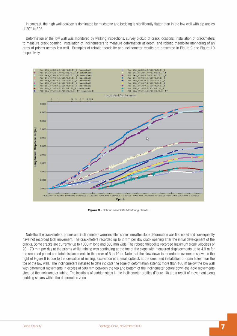
Deformation of the low wall was monitored by walking inspections, survey pickup of crack locations, installation of crackmeters to measure crack opening, installation of inclinometers to measure deformation at depth, and robotic theodolite monitoring of an array of prisms across low wall. Examples of robotic theodolite and inclinometer results are presented in Figure 9 and Figure 10 respectively.
Figure 9 – Robotic Theodolite Monitoring Results.
Note that the crackmeters, prisms and inclinometers were installed some time after slope deformation was first noted and consequently have not recorded total movement. The crackmeters recorded up to 2 mm per day crack opening after the initial development of the cracks. Some cracks are currently up to 1000 m long and 500 mm wide. The robotic theodolite recorded maximum slope velocities of 20 - 70 mm per day at the prisms whilst mining was continuing at the toe of the slope with measured displacements up to 4.9 m for the recorded period and total displacements in the order of 5 to 10 m. Note that the slow down in recorded movements shown in the right of Figure 9 is due to the cessation of mining, excavation of a small cutback at the crest and installation of drain holes near the toe of the low wall. The inclinometers installed to date indicate the zone of deformation extends more than 100 m below the low wall with differential movements in excess of 500 mm between the top and bottom of the inclinometer before down-the-hole movements sheared the inclinometer tubing. The locations of sudden steps in the inclinometer profiles (Figure 10) are a result of movement along bedding shears within the deformation zone.

� Santiago Chile, November 2009 Slope Stability
Figure 10 – Inclinometer Monitoring Results.
Inclinometer 10 Inclinometer 12
STABILITY ANALYSES
Distinct element numerical modelling has been undertaken using UDEC (Universal Distinct Element Code), refer to Cundall and Hart (4), to investigate the low wall deformation mechanism and to provide advice on possible remediation works to stabilise the low wall. The model, based on the cross section shown in Figure 6, included the low wall and high wall with the boundaries placed sufficiently remote from the open pit to avoid influencing the behaviour of the rock mass in the vicinity of the pit walls. Individual stratigraphic units, bedding shears, cleat in coal and glued joints to simulate the mining sequence were modelled. The rock mass was modelled as an elasto-plastic material with strain softening and a Mohr-Coulomb failure criterion. Cohesion, friction angle, tension and dilation angle were reduce linearly from their peak values to the residual values over 4% plastic strain. Discontinuities are described with a Coulomb slip model with residual strength. A hydrostatic stress field was assumed with the magnitude of the compressive vertical and horizontal principal stresses increasing linearly with depth of cover.
Groundwater pressure in the model was based either on the vertical depth below a defined water table or directly prescribed to each node using a self-developed Fish program (UDEC built-in programming language). In both cases, pore water pressures remain constant at a given location during an analysis until the water table or the prescribed pore water pressure value is altered (in response to mining). UDEC does not permit coupling of pore pressure within the blocks with the change in stress acting on the block. The resulting inherent assumption of water pressure remaining constant whilst the rock mass is undergoing volumetric changes due to stress redistribution may, in some cases, introduce behaviour in the model that differs significantly from observed behaviour. Pore pressure is expected to drop in the mining damaged zones due to dilation and the formation of new fractures. The groundwater pressure value was used to calculate the effective stress state acting on the joints. The effect of joint aperture and water flow along the joints was not considered in the model.
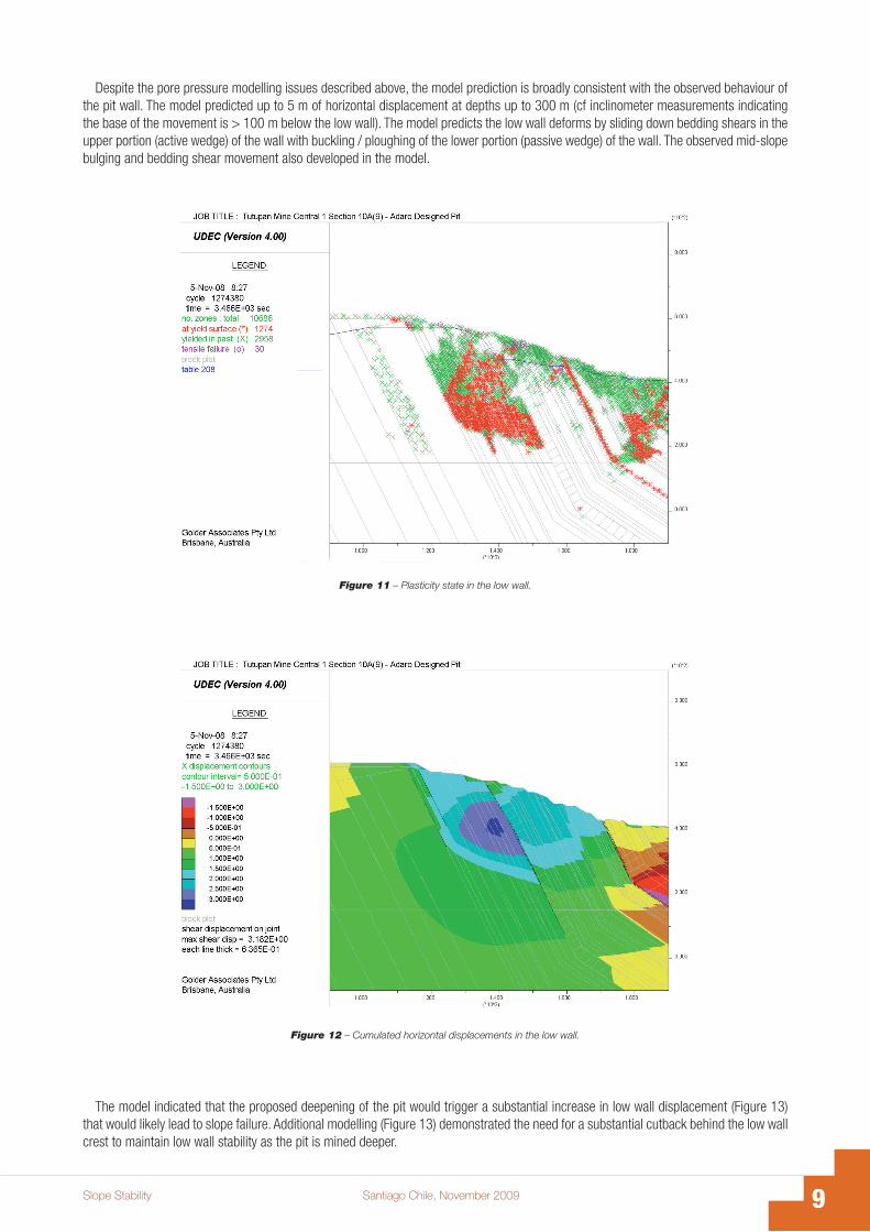
The historic mining sequence for this location was simulated with the displacements, velocities and plasticity state monitored for all stages of the mining sequence. The plasticity state and cumulated horizontal displacements in the low wall are plotted in Figure 11 and Figure 12 respectively for the current pit profile. The analysis indicates that the current pit low wall is marginally stable with the potential for a large deep seated failure. A large band of active rock mass shearing is present in the low wall mudstone below the T119 coal seam and tensile failure (tension cracking) is present where the green sandstone is exposed in the pit. The middle of the shearing band is located ~ 260 m vertically below the elevation of the top of the waste dump. Inspection of the plasticity plots before and after the stage shown in Figure 11 indicate the zone of shearing commenced higher in the slope and is moving deeper as the analysis progresses. This behaviour is probably due to stress being redirected deeper into the slope away from the zone of shearing with this redistribution being sufficient to trigger a progressive wave of shearing that travels deeper into the slope. The mudstone below T119 is susceptible to failure due to its low strength and the fully saturated conditions. The lack of coupling of pore pressure within the rock to volumetric changes probably accentuates the progressive deepening of the zone of shearing. The likely in situ reduction in pore pressure due to dilation or new fracture generation may be sufficient to prevent the band of shearing from travelling deeper into the rock mass.
�Slope Stability Santiago Chile, November 2009
Figure 11 – Plasticity state in the low wall.
Figure 12 – Cumulated horizontal displacements in the low wall.
Despite the pore pressure modelling issues described above, the model prediction is broadly consistent with the observed behaviour of the pit wall. The model predicted up to 5 m of horizontal displacement at depths up to 300 m (cf inclinometer measurements indicating the base of the movement is > 100 m below the low wall). The model predicts the low wall deforms by sliding down bedding shears in the upper portion (active wedge) of the wall with buckling / ploughing of the lower portion (passive wedge) of the wall. The observed mid-slope bulging and bedding shear movement also developed in the model.
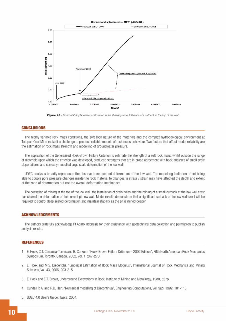
The model indicated that the proposed deepening of the pit would trigger a substantial increase in low wall displacement (Figure 13) that would likely lead to slope failure. Additional modelling (Figure 13) demonstrated the need for a substantial cutback behind the low wall crest to maintain low wall stability as the pit is mined deeper.
�0 Santiago Chile, November 2009 Slope Stability
Figure 13 – Horizontal displacements calculated in the shearing zone: Influence of a cutback at the top of the wall.
CONCLUSIONS
The highly variable rock mass conditions, the soft rock nature of the materials and the complex hydrogeological environment at Tutupan Coal Mine make it a challenge to produce reliable models of rock mass behaviour. Two factors that affect model reliability are the estimation of rock mass strength and modelling of groundwater pressure.
The application of the Generalised Hoek-Brown Failure Criterion to estimate the strength of a soft rock mass, whilst outside the range of materials upon which the criterion was developed, produced strengths that are in broad agreement with back analyses of small scale slope failures and correctly modelled large scale deformation of the low wall.
UDEC analyses broadly reproduced the observed deep seated deformation of the low wall. The modelling limitation of not being able to couple pore pressure changes inside the rock material to changes in stress / strain may have affected the depth and extent of the zone of deformation but not the overall deformation mechanism.
The cessation of mining at the toe of the low wall, the installation of drain holes and the mining of a small cutback at the low wall crest has slowed the deformation of the current pit low wall. Model results demonstrate that a significant cutback of the low wall crest will be required to control deep seated deformation and maintain stability as the pit is mined deeper.
ACKNOWLEDGEMENTS
The authors gratefully acknowledge Pt Adaro Indonesia for their assistance with geotechnical data collection and permission to publish analysis results.
REFERENCES
1. E. Hoek, C.T. Carranza-Torres and B. Corkum, “Hoek-Brown Failure Criterion – 2002 Edition”, Fifth North American Rock Mechanics Symposium, Toronto, Canada, 2002, Vol. 1, 267-273.
2. E. Hoek and M.S. Diederichs, “Empirical Estimation of Rock Mass Modulus”, International Journal of Rock Mechanics and Mining Sciences, Vol. 43, 2006, 203-215.
3. E. Hoek and E.T. Brown, Underground Excavations in Rock, Institute of Mining and Metallurgy, 1980, 527p.
4. Cundall P. A. and R.D. Hart, “Numerical modelling of Discontinua”, Engineering Computations, Vol. 9(2), 1992, 101-113.
5. UDEC 4.0 User’s Guide, Itasca, 2004.