dvac concept description: offset gregorian dish — dvac-1 prime focus dish — dvac-2 卢雨 (yu...
TRANSCRIPT

DVAC CONCEPT DESCRIPTION: OFFSET GREGORIAN DISH — DVAC-1PRIME FOCUS DISH — DVAC-2
卢雨 (Yu Lu), Vice Director @JLARTJoint Lab. for Radio Astronomy and TechnologyNov. 2011, TaejonEmail. [email protected]

DVAC Design Principle
DVAC-1 Main Specifications
Concept Design
Main Specification Budget
DVAC-2 Specs
Concept Design
Specification Budget
Outline
DVAC Design Principle
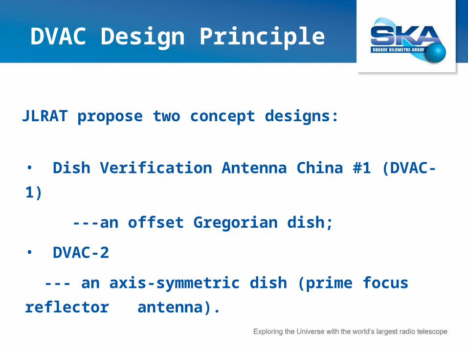
• Dish Verification Antenna China #1 (DVAC-1)
---an offset Gregorian dish;
• DVAC-2
--- an axis-symmetric dish (prime focus reflector
antenna).
JLRAT propose two concept designs:
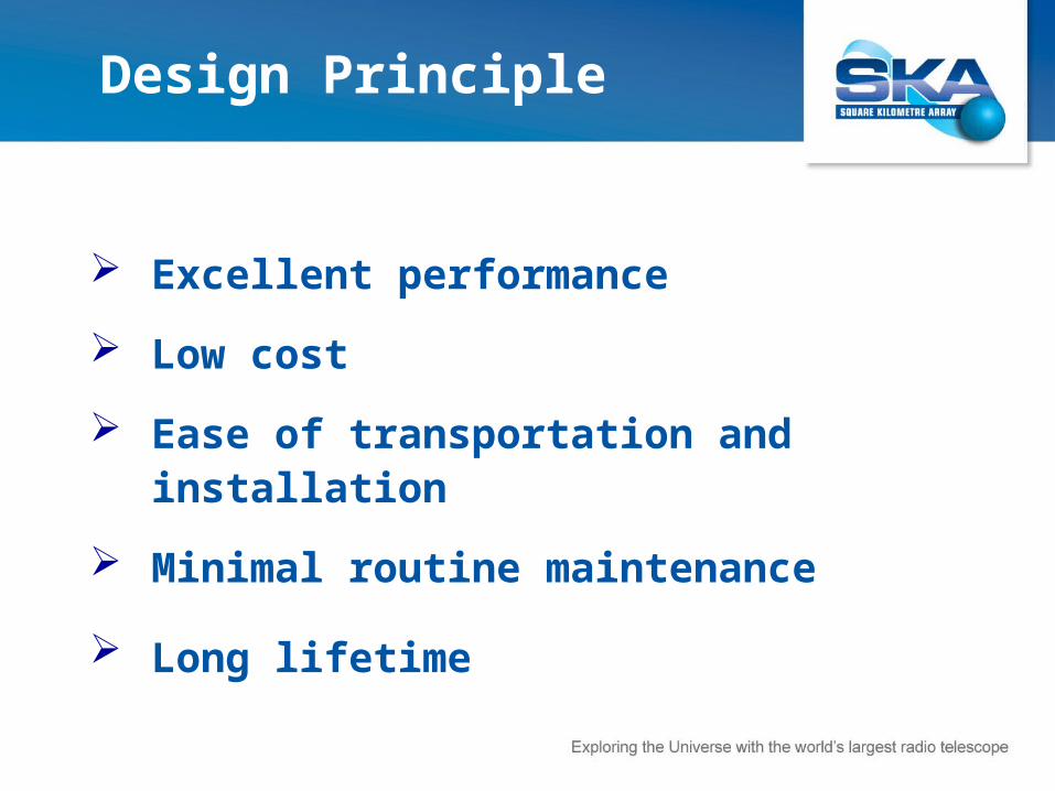
Excellent performance
Low cost
Ease of transportation and installation
Minimal routine maintenance
Long lifetime
Design Principle

DVAC CONCEPT DESCRIPTION:
OFFSET GREGORIAN DISH — DVAC-1
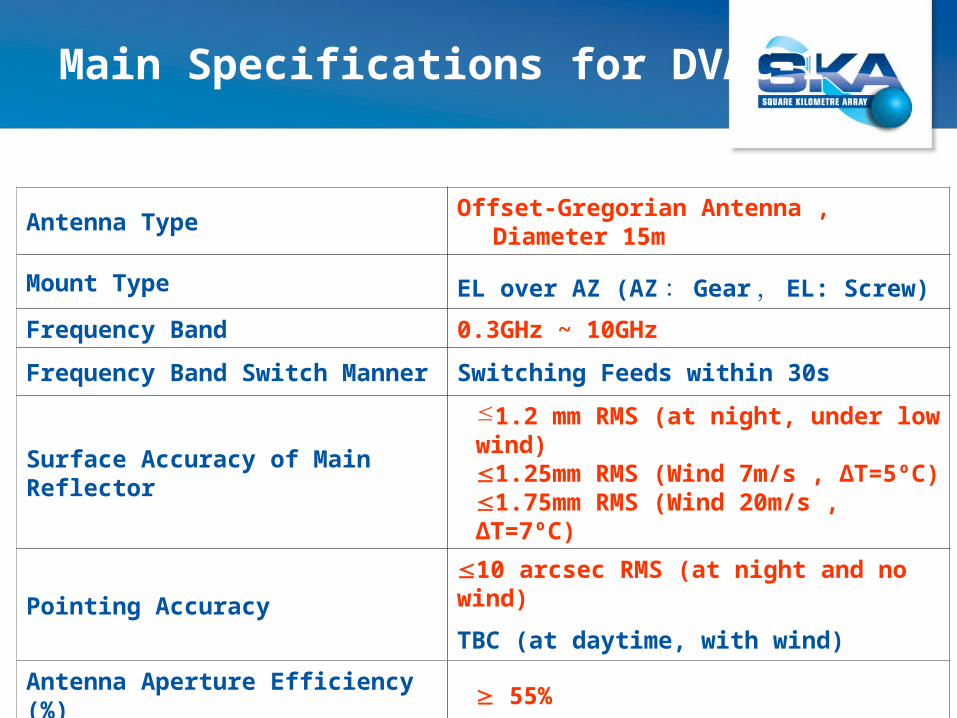
Antenna Type Offset-Gregorian Antenna , Diameter 15m
Mount Type EL over AZ (AZ : Gear , EL: Screw) Frequency Band 0.3GHz ~ 10GHz
Frequency Band Switch Manner Switching Feeds within 30s
Surface Accuracy of Main Reflector1.2 mm RMS (at night, under low wind)1.25mm RMS (Wind 7m/s , ΔT=5ºC)1.75mm RMS (Wind 20m/s , ΔT=7ºC)
Pointing Accuracy10 arcsec RMS (at night and no wind)
TBC (at daytime, with wind) Antenna Aperture Efficiency (%) 55%
First Sidelobe Level -18dB
Main Specifications for DVAC-1

Design and Manufacture
Concept Design
Block Diagram of 15 Meter Antenna System
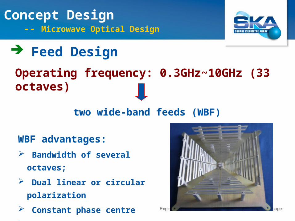
Feed Design
Operating frequency: 0.3GHz~10GHz (33 octaves)
Concept Design -- Microwave Optical Design
two wide-band feeds (WBF)
WBF advantages: Bandwidth of several octaves;
Dual linear or circular polarization
Constant phase centre
Equal E- and H-plane beamwidth

Concept Design --- Microwave Optical Design
Feed Design
Feed 1(0.3GHz ~ 1.5GHz ) and Feed 2(1.5GHz ~ 10GHz )
(Eleven Feed)
Simulation Model
Frequency(GHz)
Length×Width×Height(mm)
Weight(kg)
0.3~1.5 1040×1040×350 20
1.5~10 250×250×120 8

Concept Design --- Microwave Optical Design
Feed Design
Radiation Patterns of Feed1 at 0.3, 0.9 and 1.5GHz
Radiation Patterns of Feed2 at 1.5, 6 and 10GHz
Illuminating range
Illuminating range
Subreflector Edge Taper: -9 ~ -15dB

Single integrated main reflector
Minimal spar structure
Turning head design with a lead
screw elevation actuator
Support and interchange
mechanism for a PAF and 3 SPFs
or 2 WBFs.
Concept Design --- Structure Design
Al Skin
Z-type Rib
Gluing & Riveting
Gluing
Al Skin
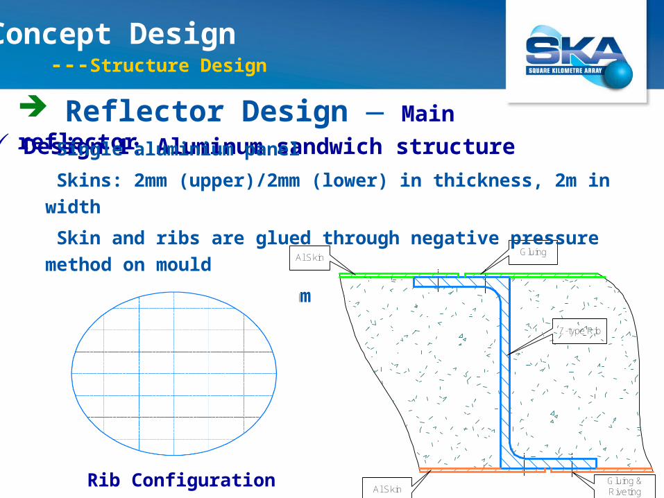
Reflector Design — Main reflector Design 1: Aluminum sandwich structure
Single aluminium panel
Skins: 2mm (upper)/2mm (lower) in thickness, 2m in width
Skin and ribs are glued through negative pressure method on mould
Surface accuracyσ≤0.8mm
Rib Configuration
Concept Design ---Structure Design

Reflector Design — Main reflector
Design 2: Carbon fibre sandwich structure
Single carbon fiber panel
Carbon fiber skins: 1.5mm (top)/1.5mm (bottom) in thickness
Polyurethane foam: in the middle Surface accuracyσ≤0.8mm
Concept Design (2) Structure Design

Reflector Design — Back structure
The backup structure is based on US TDP design with
some modifications.
Concept Design ---Structure Design

Reflector Design — Subreflector
Magnesium material, 30% lighter than aluminum alloy.
Surface accuracy σ≤0.25mm
Concept Design ---Structure Design
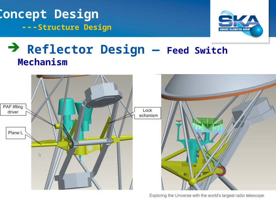
Reflector Design — Feed Switch Mechanism
Concept Design ---Structure Design

Elevation Part
Azimuth Part
Pedestal
Mount Design
Concept Design --- Structure Design

Mount Design — Azimuth part
Dual-motor anti-backlash
drive
External gear bearing, easy
to maintain
Seal cover is used to exclude
dust and sand
Concept Design --- Structure Design

Mount Design — Elevation part A planetary reducer with a ball screw drive is used
for the elevation part without a counterweight.
Concept Design ---Structure Design
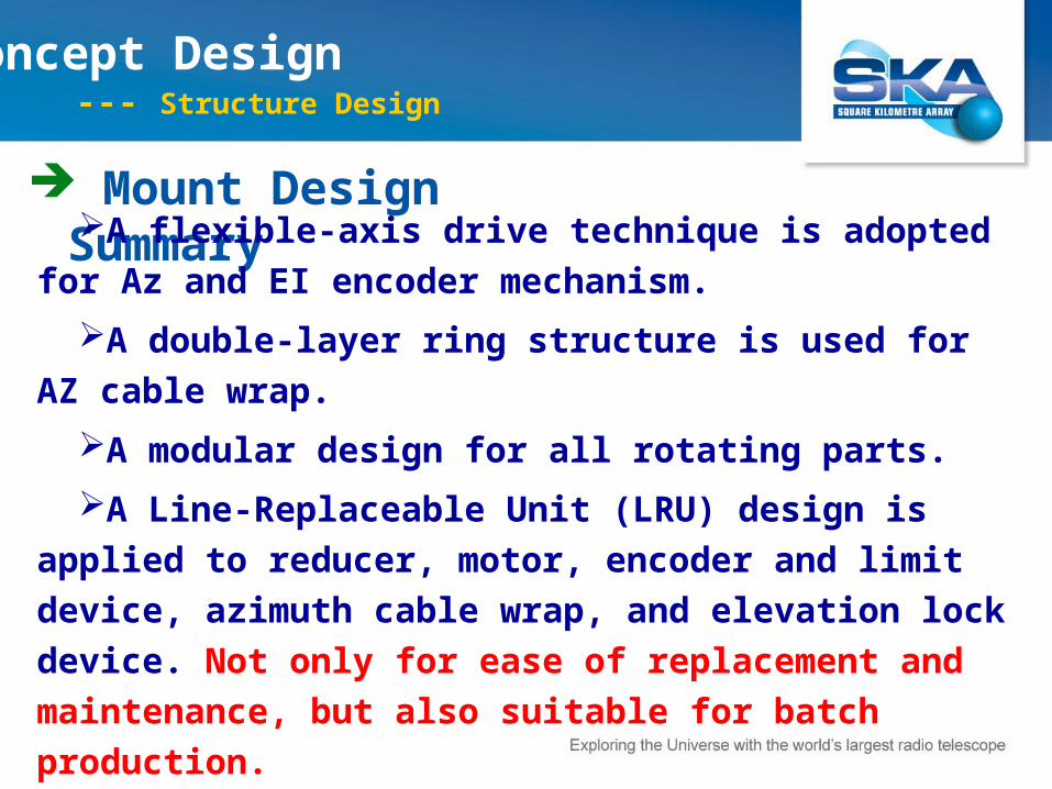
Mount Design Summary A flexible-axis drive technique is adopted for Az and
EI encoder mechanism.
A double-layer ring structure is used for AZ cable
wrap.
A modular design for all rotating parts.
A Line-Replaceable Unit (LRU) design is applied to
reducer, motor, encoder and limit device, azimuth cable
wrap, and elevation lock device. Not only for ease of
replacement and maintenance, but also suitable for batch
production.
Concept Design --- Structure Design

ITEM WEIGHT (aluminum, Kg) WEIGHT (carbon fibre, Kg)
Reflector 7250 7050
Mount 11250 11250
Total weight 18500 18300
Weight of Dish
Concept Design ---Structure Design

Structural Mechanics Analysis
EL=10° EL=90°
Finite Element Model
Concept Design --- Simulation
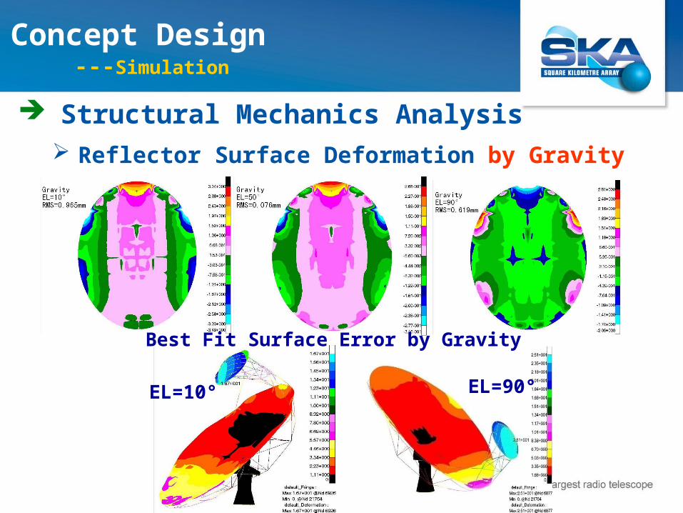
Reflector Surface Deformation by Gravity
Structural Mechanics Analysis
EL=10° EL=90°
Best Fit Surface Error by Gravity
Concept Design ---Simulation
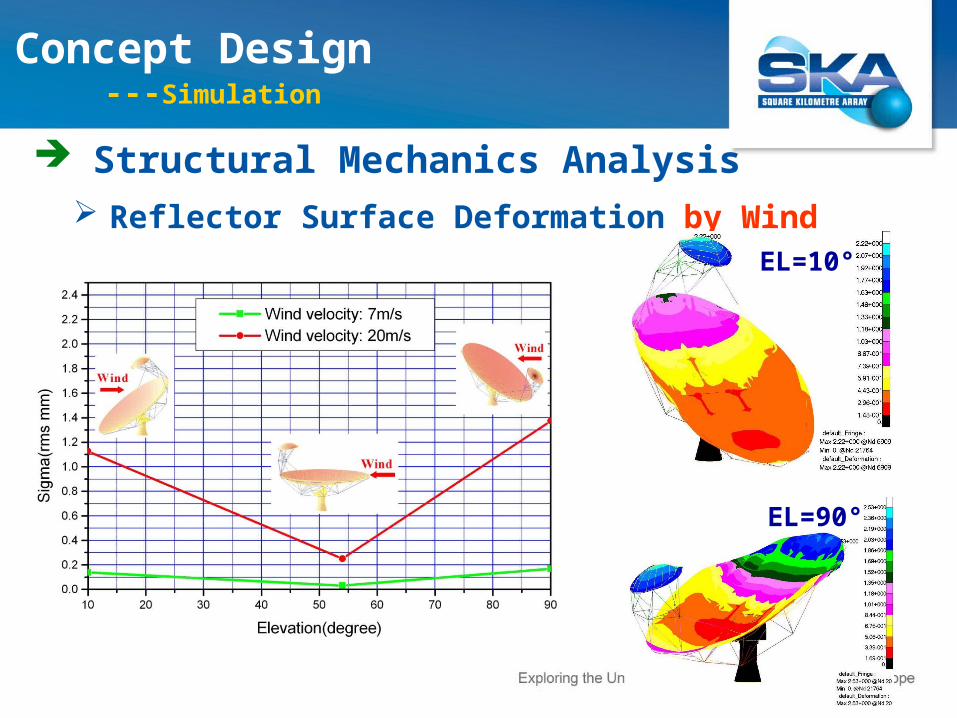
Reflector Surface Deformation by Wind
Structural Mechanics Analysis
EL=10°
EL=90°
Concept Design ---Simulation

Reflector Surface Deformation by Temperature
Structural Mechanics Analysis
Temperature Difference 2°C 5°C 7°C
Surface Error (r.m.s. mm) 0.081 0.203 0.284
Concept Design --- Analysis

Strength Analysis
Elevation(degree)
Wind speed (m/s)
GravityMax. stress
(MPa)Safety
coefficient
10° 20 √ 77.4 4.5
54° 20 √ 80.3 4.3
90° 20 √ 150 2.3
54° 45 √ 150 2.3
Structural Mechanics Analysis
Concept Design --- Analysis
The analysis results show that the structural
performance of antenna can probably meet the
SKA requirements
Conclusion
Structural Mechanics Analysis
Concept Design

Antenna control unit (ACU)
Feed Control
Antenna drivers
Motors
Power distribution devices
Encoders
Local control pendant
Limit and safety protection
device
4. Concept Design --- Servo Control Design

--- Full Radiation Pattern Calculation
Main Specification Budget
-180 -135 -90 -45 0 45 90 135 180-70
-60
-50
-40
-30
-20
-10
0
Angle [deg]
Re
lativ
e P
ow
er
[dB
]
phi=0°phi=90°
-180 -135 -90 -45 0 45 90 135 180-90
-75
-60
-45
-30
-15
0
Angle [deg]
Re
lativ
e P
ow
er
[dB
]
phi=0°phi=90°
-150 -100 -50 0 50 100 150-100
-80
-60
-40
-20
0
Angle [dB]
Re
lativ
e P
ow
er
[dB
]
phi=0°phi=90°
-180 -135 -90 -45 0 45 90 135 180-120
-100
-80
-60
-40
-20
0
Angle [deg]
Re
lativ
e P
ow
er
[dB
]
phi=0°phi=90°
f=0.3GHz f=1.5GHz
f=6.0GHz f=10GHz

First sidelobe: less than -19.73dB
Main Specification Budget
Frequency(GHz)
First sidelobe (dB)
0° plane 90° plane
0.3 (-22.77, -21.87) (-25.51, -25.51)
1.5 (-21.22, -20.38) (-24.37, -24.37)
6 (-21.21, -20.13) (-24.64, -24.64)
10 (-21.35, -19.73) (-24.24, -24.24)
--- Full Radiation Pattern Calculation
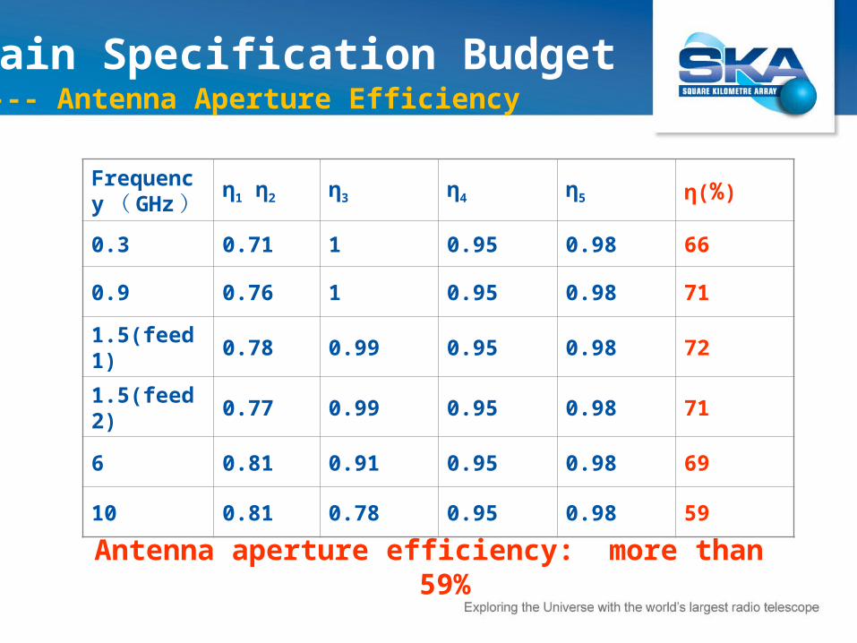
Antenna aperture efficiency: more than 59%
Frequency( GHz ) η1 η2 η3 η4 η5 η(%)
0.3 0.71 1 0.95 0.98 66
0.9 0.76 1 0.95 0.98 71
1.5(feed 1) 0.78 0.99 0.95 0.98 72
1.5(feed 2) 0.77 0.99 0.95 0.98 71
6 0.81 0.91 0.95 0.98 69
10 0.81 0.78 0.95 0.98 59
Main Specification Budget--- Antenna Aperture Efficiency

Main Specification Budget ---Pointing accuracy
Error source (r.m.s.) Error (arcsec)Residual
error (arcsec)Modification
method
Verticality of the azimuth axis 10 3 Pointing model
Azimuth-Elevation non-orthogonality
3 3 -
Azimuth bearing run-out 4 4 -
Adjust error of sub-reflector and feed
3 3 -
Gravity deformation 11 2 Lookup table
Thermal deformation <1 <1
Wind deformation - -
Servo error 5 5
Uncertain error 3 3
Total error (RMS) 8.7 arcsec (at night and windless)

DVAC CONCEPT DESCRIPTION:
PRIME FOCUS DISH — DVAC-2

Antenna Type Prime Focus Antenna, Diameter 15m
Focal length / Diameter ratio (f/D) 0.4
Mount Type AZ-EL-POL mount (AZ, POL :Gear , EL: Screw)
Frequency Band 0.3GHz ~ 10GHz
Frequency Band Switch Manner Switching Feeds within 30s
Surface Accuracy of Main Reflector1.1 mm RMS (at night, under low wind)TBC(at daytime, with wind)
Pointing Accuracy10 arcsec RMS (at night and no wind)
TBC (at daytime, with wind) Antenna Aperture Efficiency (%) 50%
First Sidelobe Level -20dB
DVAC-2 Specifications
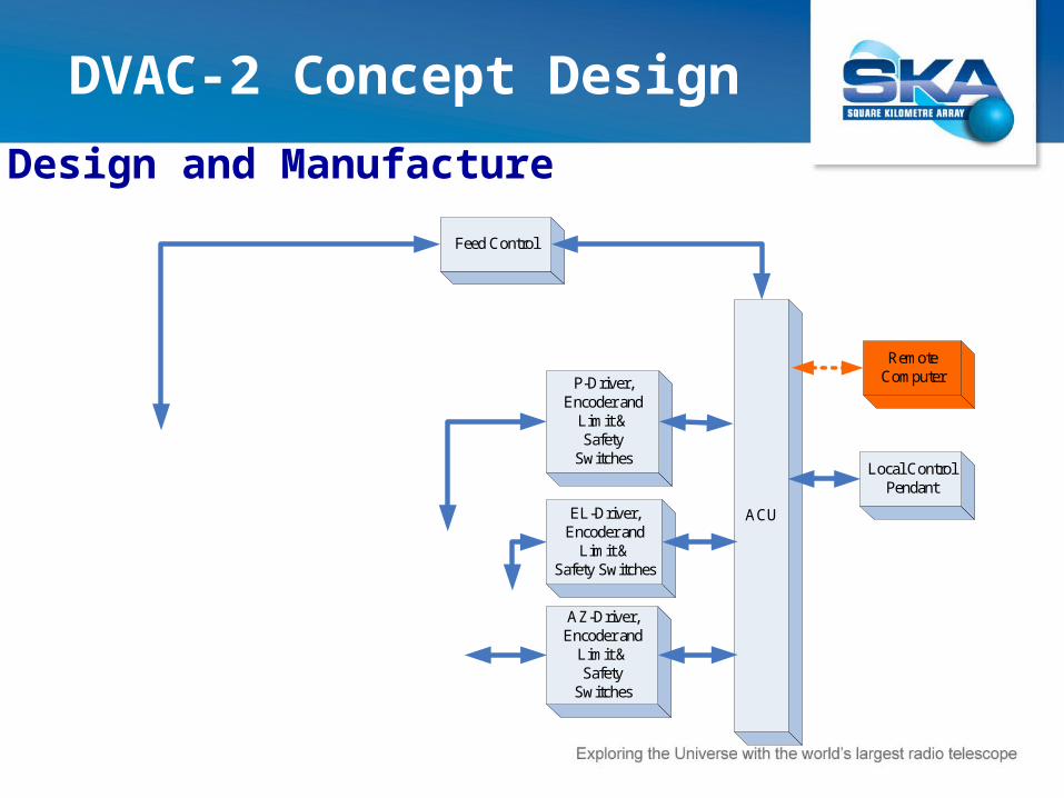
Design and Manufacture
DVAC-2 Concept Design
Feed Control
EL-Driver, Encoder and
Limit &Safety Switches
AZ-Driver, Encoder and
Limit &Safety
Switches
ACU
Remote Computer
Local Control Pendant
P-Driver, Encoder and
Limit &Safety
Switches

DVAC-2 Concept Design --- Microwave Optical Design
-40 -30 -20 -10 0 10 20 30 40-50
-40
-30
-20
-10
0
Angle [deg]
Rel
ativ
e P
ower
[dB
]
phi=0°
phi=90°
-10 -8 -6 -4 -2 0 2 4 6 8 10-70
-60
-50
-40
-30
-20
-10
0
Angle [deg]
Rel
ativ
e P
ower
[dB
]
phi=0°
phi=90°
-5 -4 -3 -2 -1 0 1 2 3 4 5-70
-60
-50
-40
-30
-20
-10
0
Angle [deg]
Rel
ativ
e P
ower
[dB
]
phi=0°
phi=90°
-3 -2 -1 0 1 2 3-80
-70
-60
-50
-40
-30
-20
-10
0
Angle [deg]
Rel
ativ
e P
ower
[dB
]
phi=0°
phi=90°
f=0.3GHz f=1.5GHz
f=6.0GHz f=10GHz
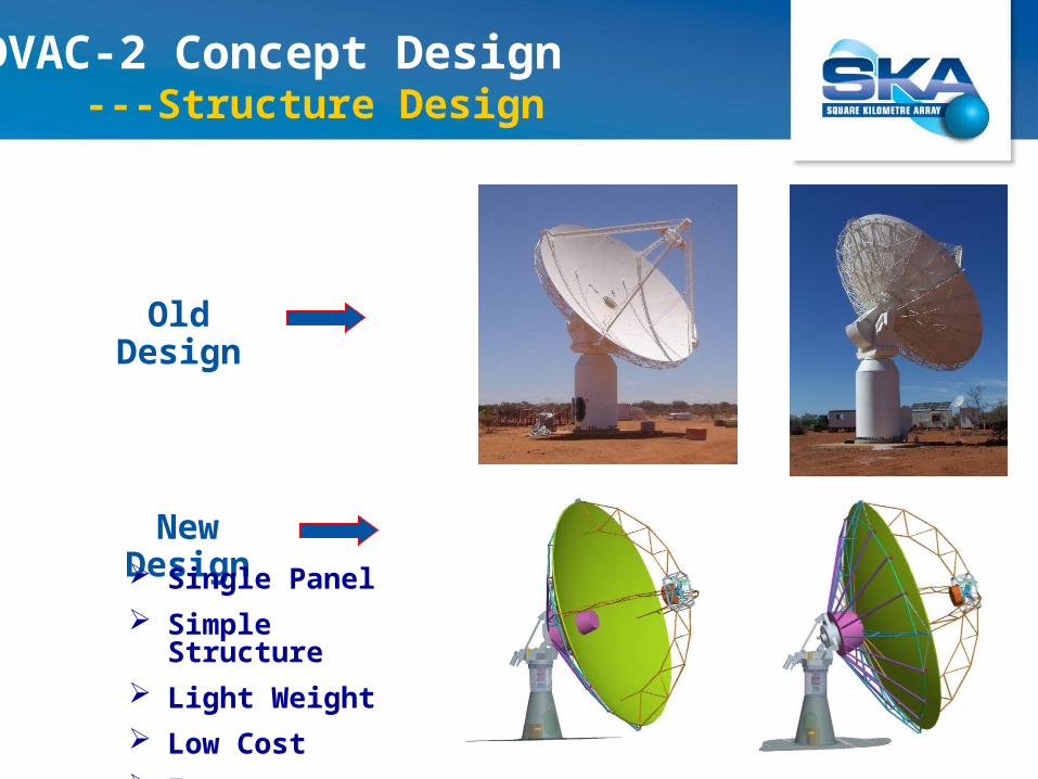
Old Design
New Design Single Panel
Simple Structure
Light Weight
Low Cost
Fast Installation
DVAC-2 Concept Design ---Structure Design

Single integrated main reflector
Minimal spar structure
Turning head design with a lead screw
elevation actuator
Four support legs and interchange
mechanism for a PAF and 3 SPFs or 2
WBSPFs.
DVAC-2 Concept Design ---Structure Design
Mount
Wrap Room
Feed Support Truss
Reflector
Feed Switch

Reflector Design
Main reflector
Back structure
Feed switch mechanism
DVAC-2 Concept Design ---Structure Design

Reflector Design — Back structure
DVAC-2 Concept Design ---Structure Design

Elevation Part
Azimuth Part
Pedestal
Mount Design
DVAC-2 Concept Design ---Structure Design
φ 2900
8413
6103
2695
Polarization Part
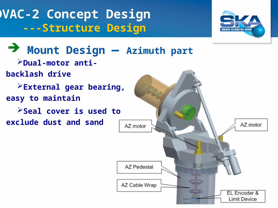
Mount Design — Azimuth part Dual-motor anti-backlash
drive
External gear bearing, easy
to maintain
Seal cover is used to exclude
dust and sand
DVAC-2 Concept Design ---Structure Design
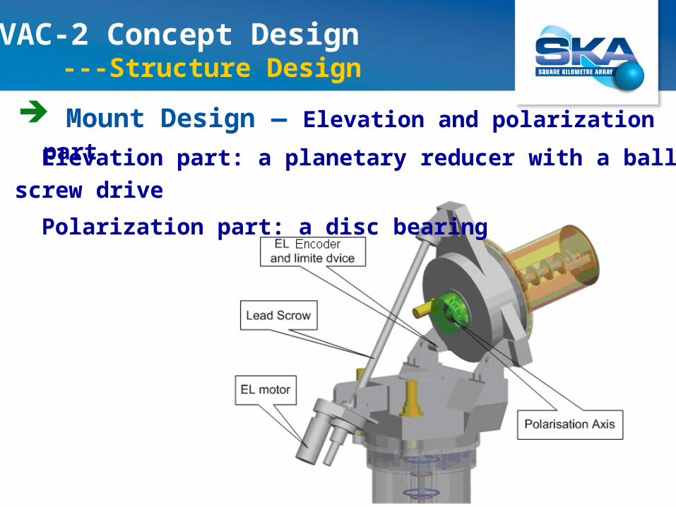
Mount Design — Elevation and polarization part
Elevation part: a planetary reducer with a ball screw drive
Polarization part: a disc bearing
DVAC-2 Concept Design ---Structure Design
Mount Design
A flexible-axis drive technique is adopted for Az and
EI encoder mechanism.
A double-layer ring structure is used for AZ cable
wrap.
A modular design for all rotating parts.
A Line-Replaceable Unit (LRU) design is applied to
reducer, motor, encoder and limit device, azimuth cable
wrap, and elevation lock device. Not only for ease of
replacement and maintenance, but also suitable for batch
production.
DVAC-2 Concept Design --- Structure Design

ITEM WEIGHT (aluminum, Kg) WEIGHT (carbon fibre, Kg)
Reflector 6800 6550
Mount 12500 12500
Total weight 19300 19050
Weight of Dish
DVAC-2 Concept Design

-180 -135 -90 -45 0 45 90 135 180-120
-90
-60
-30
0
Angle [deg]
Re
lativ
e P
ow
er
[dB
] phi=0°phi=90°
-180 -135 -90 -45 0 45 90 135 180-120
-90
-60
-30
0
Angle [deg]
Re
lativ
e P
ow
er
[dB
]
phi=0°phi=90°
-180 -135 -90 -45 0 45 90 135 180-100
-80
-60
-40
-20
0
Angle [deg]
Re
lativ
e P
ow
er
[dB
]
phi=0°phi=90°
-180 -135 -90 -45 0 45 90 135 180-70
-60
-50
-40
-30
-20
-10
0
Angle [deg]
Re
lativ
e P
ow
er
[dB
]
phi=0°phi=90°
--- Full Radiation Pattern Calculation DVAC-2 Specification Budget
f=0.3GHz f=1.5GHz
f=6.0GHz f=10GHz

First sidelobe: less than -28dB
DVAC-2 Specification Budget
Frequency(GHz)
First sidelobe (dB)
0° plane 90° plane
0.3 (-28.2, -28.2) (-28.2, -28.2)
1.5 (-28.5, -28.5) (-28.5, -28.5)
6 (-28.7, -28.7) (-28.7, -28.7)
10 (-28.9, -28.9) (-28.9, -28.9)
--- Full Radiation Pattern Calculation

Antenna aperture efficiency: more than 50%
Frequency( GHz ) η1 η2 η3 η4 η5 η(%)
0.3 0.74 1 0.95 0.98 69
0.9 0.71 1 0.95 0.98 66
1.5(feed 1) 0.70 1 0.95 0.98 65
1.5(feed 2) 0.72 1 0.95 0.98 67
6 0.70 0.93 0.95 0.98 60
10 0.68 0.81 0.95 0.98 51
DVAC-2 Specification Budget--- Antenna Aperture Efficiency
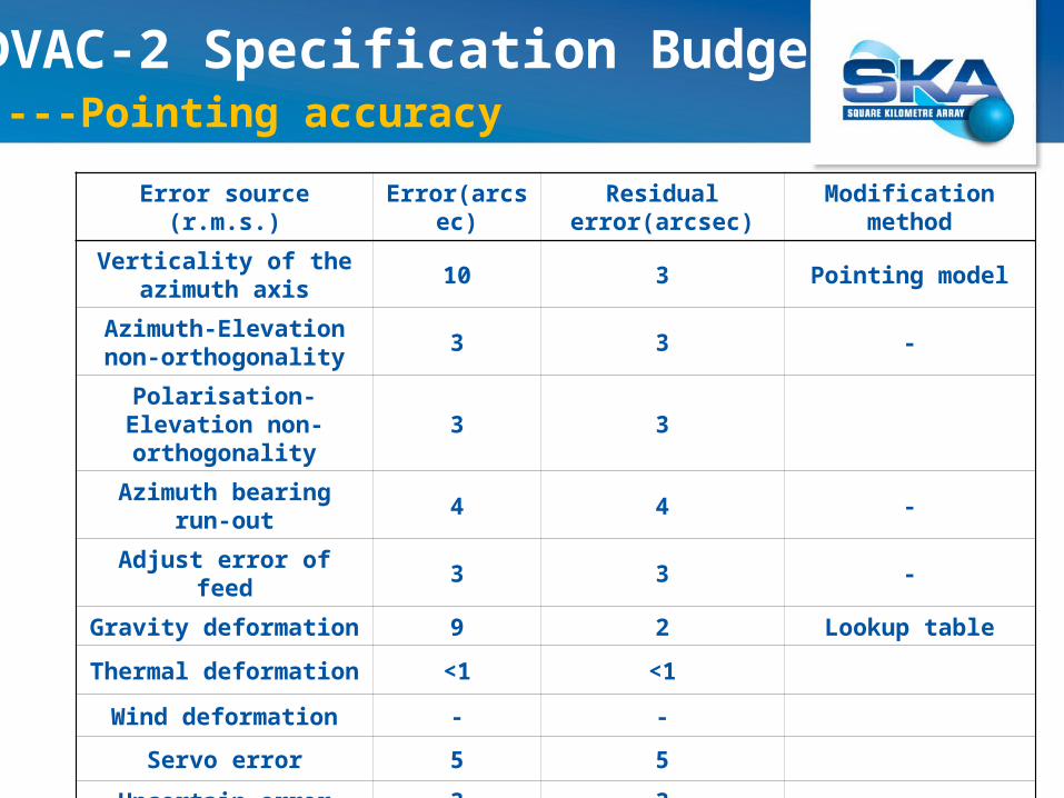
DVAC-2 Specification Budget---Pointing accuracy
Error source(r.m.s.)
Error(arcsec)
Residualerror(arcsec)
Modificationmethod
Verticality of the azimuth axis
10 3 Pointing model
Azimuth-Elevation non-orthogonality
3 3 -
Polarisation-Elevation non-orthogonality
3 3
Azimuth bearing run-out 4 4 -
Adjust error of feed 3 3 -
Gravity deformation 9 2 Lookup table
Thermal deformation <1 <1
Wind deformation - -
Servo error 5 5
Uncertain error 3 3
Total error(RMS) 9.2arcsec(at night and windless)

Thank You!