dynamic response of prestressed tapered timoshenko beams ... · dynamic response of prestressed...
TRANSCRIPT

33
Dynamic Response of Prestressed Tapered Timoshenko Beams to Uniform Partially
Distributed Moving Loads
Hamzat Afe Isede1 and Jacob Abiodun Gbadeyan2
1 Department of Mathematics, University of Lagos, Akoka, Nigeria.
2Department of Mathematics, University of Ilorin, Ilorin, Nigeria.
Corresponding Author’s email:[email protected]
Abstract
The dynamics of a prestressed variable cross-section Timoshenko beam subjected to a moving
partially distributed load is investigated. The Finite element method with Lagrange
interpolation functions and reduced integration element were used to model the structure.
The Newmark numerical method of integration was used to solve the resulting semi-discrete
time dependent equations to obtain the desired responses. The effects of the prestress,
moving load’s velocity, moving load’s length, and boundary conditions on the dynamic
characteristic of the beams were investigated and the results presented graphically.
Key words: Prestressed; Tapered Beam; Equal Interpolation; Weak Form.
Mathematics Subject Classification 2010: 70JXX, 74S05.
1. INTRODUCTION
Prestressing involves the application of an initial compressive load on a structure to reduce
or eliminate the internal tensile stresses that may be caused by imposed loads or by load-
independent effects such as temperature changes or shrinkage. The prestressing of beams,
done to improve the overall performance of the structure, has been widely employed in
important civil engineering structures such as bridges. Such a bridge is modeled with an axial
load, and its dynamic characteristics have been investigated. Fryba [5] studied the free and
forced vibration of a simply-supported beam subject to an axial force and a moving force.
Isede H.A. and Gbadeyan J.A.
Academy Journal of Science and Engineering (AJSE) vol 8 no 1
34
Bokaian [2, 3] presented the influence of a constant axial compressive and tensile force on
natural frequencies and normal modes of a uniform single-span beam with different boundary
conditions. Law and Lu [12] have numerically shown some effects of axial prestressing upon
time responses. Saiidi et al. [15] determined the natural frequencies of a prestressed concrete
bridge using a simply supported axially compressed beam. The results indicate that an increase
in the magnitude of the prestressed force reduces the natural frequencies of prestressed beams.
Dallasta and Dezi [4] indicated that the effect of the prestress force on the beam bending
vibration frequencies is negligible based on a linear model. Kanaka and Venkateswara [9] have
showed that the prestress force reduces the natural frequency of the lower modes, based on a
Rayleigh-Ritz formulation that describes prestressing as an external axial compressive force
only. Miyamoto et al. [13] dealt with the dynamic behavior of a prestressed beam strengthened
with external tendons, where they considered the change in the tendon force along with the
compressive force effect, by an incremental formulation of the equations of motion of the
beam. Their result showed that the calculated natural frequencies tend to decrease as the
amount of the prestressing force increased. Kerr [10] studied experimentally and analytically
the dynamic response of a prestressed beam. It was found that the magnitude of the prestress
force for a cable that passes through the centroid of the beam cross-section has no effect upon
the dynamic response of the beam.
Hamed and Frostig [6] studied the effect of the magnitude of the prestress force on the natural
frequencies of prestressed beams, and revealed that the prestress force does not affect the
dynamic behavior of general prestressed beams, and reveals that the natural frequencies of
bonded prestressed beams can be determined through a linear elastic beam theory with an
equivalent moment of inertia of the composite section, while those of the unbonded prestressed
beams can be determined by the proposed model. We note here that no external load of any
sort was involved in his study.The researches so far mentioned were all based on the Euler-
Bernoulli beam theory. Prestressed studies involving Timoshenko beam theory were much
fewer. Auciello and Ercolano [1] proposed a general technique for determining the natural
frequencies of non-uniform Timoshenko beams. Kocaturk and Simsek [11] analysed the
dynamic responses of a damped Timoshenko beam under the combination of an eccentric
compressive load and a moving harmonic force. Jiang and Ye [8] analysed the free vibration
and transient wave in a prestressed Rayleigh-Timoshenko beam subjected to arbitrary
transverse forces using the method of reverberation-ray matrix. Their results showed that
frequencies decreased with the prestress.
The objective of this paper is to investigate the dynamic response of prestressed tapered
Timoshenko beams to uniform partially distributed moving loads. The prestress is assumed
to result from the initial loading by axial forces. Regarding the above cited references, two
unique features are considered in the present work. Firstly the beam is semi-tapered;
meaning that one dimension of the cross-section gradually reduces in length according to the
taper-ratio by Hsu et al [7]. Secondly, the prestress is assumed to vary spatially.
Isede H.A. and Gbadeyan J.A.
Academy Journal of Science and Engineering (AJSE) vol 8 no 1

35
With a literature survey, and to the best of the authors' knowledge, no work was found
reported on the dynamic response of a prestressed tapered Timoshenko beam subject to
partially distributed moving load. In the current study, we evaluate the dynamic response of
a prestressed non-uniform Timoshenko beam under a uniform partially distributed moving
load, using the finite element method with the Lagrange interpolation function. Firstly the
non-uniform continuous beam was replaced by a discrete system made up of beam elements.
The semi-discrete, time dependent elemental and overall stiffness, mass, and centripetal
matrices as well as the elemental and overall load vectors were then derived with the aid of
the Rayleigh-Ritz method. Newmark numerical integration method was used to obtain the
desired responses from the semidiscrete set of integral equations.
Following this introduction, the remainder of the paper is organized as follows. Section 2
presents the mathematical formulation of the problem, while Section 3 involves the first part
of the finite element analysis, the spatial approximation. The assembly of the element equations
and the imposition of the boundary conditions are also included in Section 3. In Section 4, the
time approximation is carried out as the solution of element equations. Numerical examples
are given in Section 5, and in Section 6 the concluding remarks brings the discussion to an end.
2. FINITE ELEMENT FORMULATION
Consider a 2-node tapered beam element i,j undergoing a compressive axial force Q
(prestressed) shown in Figure 1. In the figure, l, A(x), I(x) are the element length, cross-
sectional area, and moment of inertia, respectively.
The element has two degrees of freedom at each node, a lateral translationu, and a rotation
about an axis normal to the plane (x, z), w. Thus the vector of nodal displacements contains
four components
, , ,T
i i j jv u w u w (1)
Figure 1. A two-node prestressed beam element
i j
ui
wi
uj
wj z
x l, A(x), I(x)
Q Q
Isede H.A. and Gbadeyan J.A.
Academy Journal of Science and Engineering (AJSE) vol 8 no 1

36
where (and hereafter) the superscript T refers to the transpose of a vector or a matrix.
To derive the stiffness, centripetal, and mass matrices for the finite element analysis, an
interpolation scheme is required. Using simple linear functions for both the lateral
displacement u and rotation w, that have been widely adopted [16], are possible. However,
a special technique should be adopted to prevent a possible shear locking problem [17].
Reddy demonstrated that a Timoshenko beam element formulated in the context of the
equal interpolation, with reduced integration of the shear stiffnesses, poses many
advantages, including the absence of shear locking. The present study adopted this equal
interpolation approach and we obtained the approximation functions as:
3
1
3
1
( , ) ( ) ( )
( , ) ( ) ( )
j jj
j jj
u x t x u t u
w x t x w t w
(2)
wherej
andj
, 1,2,3j are the Lagrange quadratic approximation functions for ( )u x and
( )w x respectively.The detail of the expressions forj
andj
, 1,2,3j are given by the
equations (21) and (22) in the Appendix.
Having derived the interpolation functions, the stiffness, centripetal, and mass matrices can
be developed by employing the Ritz technique.
Consider the equation of a pre-stressed tapered Timoshenko beam carrying a load moving at
a specified speed
2
2
2 2
2 2
( , ) 0
0q q
u u ukGA w S A q x t
x x x x t
w u w d wEI kGA w I I D
x x x t dt
(3)
where ,u x t is the deflection of the beam axis, and ,w x t is the rotation of its cross-section.
andq
are the respective densities of the beam and the load; while I and Iq are the
corresponding moments of inertia of their cross-sectional areas, respectively. A x is the cross-
sectional area of the beam; E - the elastic modulus; G - the shear modulus; k - the shear
coefficient; ,q x t - the distributed load; S(x) is the compressive axial force; t is time, and x is
the position coordinate in the axial direction[ (0, )]x L , and L is the length of the beam.
The boundary conditions for a simply supported, clamped, and cantilever beam are
respectively
Isede H.A. and Gbadeyan J.A.
Academy Journal of Science and Engineering (AJSE) vol 8 no 1
37
(0, ) ( , ) 0 ; (0, ) ( , ) 0,
(0, ) ( , ) 0 ; (0, ) ( , ) 0,
(0, ) (0, ) 0 ; ( , ) ( )( , ) 0,
x x
x x
u t u L t EIw t EIw L t
u t u L t w t w L t
u t w t EIw L t kGA w w L t
(4)
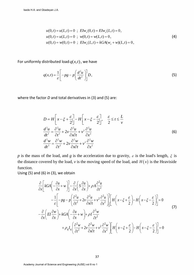
For uniformly distributed load ( , )q x t , we have
2
2
1( , ) ,
d uq x t pg p D
dt
(5)
where the factor D and total derivatives in (3) and (5) are:
2 2 2 2
2
2 2 2
2 2 2 2
2
2 2 2
,2 2 2
2
2
LD H x H x t
v
d u u u uv v
dt t x t x
d w w w wv v
dt t x t x
(6)
p is the mass of the load, and g is the acceleration due to gravity, is the load's length, is
the distance covered by the load, v is the moving speed of the load, and H x is the Heaviside
function.
Using (5) and (6) in (3), we obtain
2
2
2 2 22
2 2
2
2
2 2 22
2
12 0
2 2
2q q
u u ukGA w S A
x x x x t
u u upg p v v H x H x
x tt x
w u wEI kGA w I
x x x t
w w wI v v
x tt
20
2 2H x H x
x
(7)
Isede H.A. and Gbadeyan J.A.
Academy Journal of Science and Engineering (AJSE) vol 8 no 1

38
The moment of inertia ( )I x and area of beam cross-section of the beam ( )A x in (7) are defined
respectively by [7] as
0
0
3
( ) 1 1
( ) 1 1
b h
h
x xI x I
L L
xA x A
L
(8)
where I is the variable moment of inertia of the beam, A is the variable area of beam cross-
section, and L is the length of the beam. A0 and I0 are the cross-sectional area and moment of
inertia at x=0. 1b b and 1h h are functions of the taper ratios of the beam b and
h respectively.
Following the work of Kien [18] we define the prestress parameter in (7), with axial force1
S ,
as:
2
1( )( )
LS x S
EI x (9)
The weak forms of the equations (7) over a typical element are
2 2
2 2
2 2
2 2
2 2
1 11 1 12 2
0
2 2 2
1 1 1 3 1 12
2( ) (0) 0
el
e e
e
dR dRu u u pg p ukGA w S R A dx R dx R dx
dx x dx x t t
pv u pv uR dx R dx R l Q R Q
x t x
(10)
2
2
2 2
2 2
2 2
22 2 22 2
0
2 22
2 2 2 4 2 222 ( ) (0) 0
e
e
e e
l
q q
e e
q q q q e
dR w u w wEI R kGA w R I dx I R dx
dx x x t t
w wv I R dx v I R dx R l Q R Q
x t x
(11)
Isede H.A. and Gbadeyan J.A.
Academy Journal of Science and Engineering (AJSE) vol 8 no 1

39
In (10) and (11),1( )R x and
2( )R x are the weight functions and ( 1,2,3,4)e
iQ i as defined in (12),
are the shear forces and bending moments respectively at the boundaries.
1 2
00
3 4
;
;
ee
e e
xx
e e
x lx l
u u wQ kGA w S Q EI
x x x
u u wQ kGA w S Q EI
x x x
(12)
Now, employing the Ritz technique, where the weight functions 1( )R x and
2( )R x are defined
for each of the approximation function ( )x and ( )x respectively. These, together with (2)
in (10) and (11) yields the set of equations of motion for a typical element,
3 3 3 3
1
1 1 1 1
0ij ij ij j ik k ij ij j ij j i
j k j j
K K K u K w M M u C u F
(13)
3 3 3 3
2
1 1 1 1
0ik ik k ij j ik ik k ik k i
k j k k
K K w K u M M w C w F
(14)
Where in (13) and (14),the terms K, M, C, and F, along with their corresponding superscripts
and subscripts are defined in (23) to (27) in the Appendix. They are the element stiffness
matrices, element centripetal matrices, the element mass matrices, and the element applied
forces vector {f} plus the element internal generalized forces vector {Q}.
3. GOVERNING EQUATION AND ITS SOLUTION
Consider a prestressed tapered Timoshenko beam carrying a load moving at a specified
speed, travelling along the beam from left to right. Following the standard procedure of the
finite element method, the beam is discretized into a number of finite elements. The above
equations of motion of the beam (13) and (14), can be written in terms of the finite element
analysis as
KV CV MV F (15)
Isede H.A. and Gbadeyan J.A.
Academy Journal of Science and Engineering (AJSE) vol 8 no 1

40
where K, C, and M, are the structural stiffness, centripetal, and mass matrices, respectively.
These matrices are obtained by assembling the corresponding element matrices in the
standard way of the finite element method; V , /V V t and 2 2/V V t are the vectors of
structural nodal displacements, velocities, and accelerations, respectively; F is the addition of
the assembled element applied forces vector {f} and the element internal generalized forces
vector {Q}.
The system of equation (15) is solved by the Newmark [19, 20] direct integration method
using both the linear and average acceleration formulae.
The displacement V t the velocity V t and the acceleration V t in (15) are defined by the
Newmark equations:
2 2
11 12s s s s sV V tV t V t V (16)
1 12
s s s s
tV V V V
(17)
The parameter in (16) defines the variation of acceleration over a time step and determines
the stability and accuracy characteristics of the method. The notations used[19] are as
defined in (18):
1 1 1at time ; at time ;
s s s s s sV V t V V t t t t
(18)
Writing (17) for 1sV and substituting it into (16), applying it to (15), and collecting like terms
results in:
1 1 , 1ˆ ˆ
s s s sK V F
(19)
where
Isede H.A. and Gbadeyan J.A.
Academy Journal of Science and Engineering (AJSE) vol 8 no 1

41
1 1 3 1 6 1
, 1 1 1 3 4 5 1 6 5 7
3 4 3 5 6 72
ˆ
ˆ
1 1 1 1, , 1 , , 1
( ) 2 2 ( ) 4
s s s s
s s s s s s s s s s s
K K a M a C
F F M a V a V a V C a V a V a V
a a a t a a a tt t
(20)
4. NUMERICAL INVESTIGATIONS
Using the finite element formulated in Section 2 and the numerical algorithm described in
Section 3, a computer code in Matlab was developed and used in the dynamic analysis. To
investigate the dynamic response, the beam with the following geometry and material data
was adopted herewith.
L = 17.5m; =2400kgm-3; E = 2.021011Nm-2; G=7.71010Nm-2; k = 5/6; q = 240kgm-3;
Iq=0.0012m4; p = 1062kg; v = 30ms-1; = 0.2m; g = 9.8ms-2. The magnitude of the prestress S
= 450000kN will be subjected to variations.
The length of each element is given as:
L1 = 1.25m, L2 = 1.25m, L3 = 1.5m, L4 = 1.5m, L5 = 1.75m,
L6 = 1.75m, L7 = 2m, L8 = 2m, L9 = 2.25m, L10 = 2.25m.
The cross-section of the beam is such that its width is uniform from end-to-end, and is given
as 0.41m. The non-uniform (tapered) nature of the beam is determined by its varying
depth(height), which is given from left to right as:
H0 = 0.52m, H1 = 0.5m, H2 = 0.48m, H3 = 0.46m, H4 = 0.44m, H5 = 0.42m, H6 = 0.4m,
H7 = 0.38m, H8 = 0.36m, H9 = 0.34m, H10 = 0.32m.
Three types of boundary conditions, namely simply supported (SS), clamped (CC), and
cantilevered are considered.
The beam's cross-sectional area ( )A x and moment of inertia ( )I x are calculated using (8). The
varying value of the prestress, ( )S x is calculated by (9).
The computation is performed with the beam discretized into ten unequal elements.
4.1 Effect of the prestress on the dynamic response
A change was observed in the deflection and rotation of the beam when the prestress was
increased from 0KN to 450000KN, 450000KN to 900000KN, and 900000KN to 1350000KN.
There was a gradual reduction in the deflection and rotation responses when the prestress was
increased. The result is shown in Figure 2.
Isede H.A. and Gbadeyan J.A.
Academy Journal of Science and Engineering (AJSE) vol 8 no 1

42
4.2 Effect of the load's moving velocity on the dynamic response
The effect of load's velocity on the dynamic response of the beam under consideration was
increased as the moving velocity of the load increased from 1.3m/s to 1.7m/s. The result is
shown in Figure 3.
4.3 Effect of the load's length on the dynamic response
To investigate the effect of the moving load's length on the dynamic response of the beam, the
load’s length was increased from 0.2m to 0.4m. The dynamics response of the beam decreased
as the load’s length increased as Figure4shows.
Isede H.A. and Gbadeyan J.A.
Academy Journal of Science and Engineering (AJSE) vol 8 no 1

43
4.4 Effect of changes in boundary conditions on the dynamic response
The maximum amplitude of deflection u and rotation w are far higher with the simply
supported boundary than for both the cantilever and clamped boundaries. As seen in Figures
5, the values for simply supported boundary are ten-thousandth compared with the actual
values of the cantilever and clamped boundaries.
5. CONCLUSION
The dynamic response of prestressed tapered Timoshenko beam was investigated in this
paper. We have shown that there exists a gradual decrease in the dynamic response of the
beam as the prestress is increased. This implies that a higher magnitude of prestress reduces
the vibration of the structure, and hence, may improve its durability. We have also shown
that other characteristics such as load’s velocity and length, as well as beam’s boundary
conditions, also affect the dynamic response of the present beam.
Isede H.A. and Gbadeyan J.A.
Academy Journal of Science and Engineering (AJSE) vol 8 no 1

44
References
1. N. M. Auciello, A. Ercolano, A general solution for dynamic response of axially loaded
non-uniform Timoshenko beams. International Journal of Solids and Structures, 41(18-19),
(2004), 4861-4874.
2. A. Bokaian, Natural frequencies of beams under compressive axial loads. Journal of Sound
and Vibration, 126(1), (1988), 49-65.
3. A. Bokaian, Natural frequencies of beams under tensile axial loads. Journal of Sound and
Vibration, 142(3), (1990), 481-498.
4. A. Dallasta, L. Dezi, Prestress force effect on vibration frequency of concrete bridges—
discussion, ASCE Journal of Structural Engineering, 122 (4), (1996), 458-458.
5. L. Fryba, Vibration of Solids and Structures under Moving Loads. Noordhoff International
Publishing, Groningen, the Netherlands, (1972), 325-333.
6. E. Hamed, Y. Frostig, Natural frequencies of bonded and unbonded prestressed beams–
prestress force effects, Journal of Sound and Vibration, 295, (2006), 28-39.
7. J. C. Hsu, H. Y. Lai, and C. K. Chen, Free vibration of a non-uniform Euler-Bernoulli
beams with general elastically end constraints using Adomian modified decomposition
method. Journal of sound and vibration, 318, (2008), 965-981.
8. J. Jiang, G. Ye, Dynamics of a prestressed Timoshenko beam subject to arbitrary external
load, Journal of Zhejiang University-SCIENCE A (Applied Physics \& Engineering)
11(11), (2010), 898-907.
9. K. Kanaka, G. Venkateswara, Free vibration behavior of prestressed beams, ASCE Journal
of Structural Engineering 112 (7), (1986), 433-437.
10. A. D. Kerr, On the dynamic response of a prestressed beam, Journal of Sound and Vibration
49 (4), (1976), 569–573.
11. T. Kocaturk, M. Simsek, Dynamic analysis of eccentrically prestressed viscoelastic
Timoshenko beams under a moving harmonic load. Computers and Structures, 84(31-32),
(2006), 2113-2127.
12. S. S. Law, Z. R. Lu, Time domain responses of a prestressed beam and prestress
identification. Journal of Sound and Vibration, 288, (2005), 4-5.
13. A. Miyamoto, K. Tei, H. Nakamura, and J. W. Bull, Behavior of prestressed beam
strengthened with external tendons, ASCE Journal of Structural Engineering 126 (9),
(2000), 1033–1044.
14. J. N. Reddy, An Introduction to the Finite Element Method. 3ed. McGraw--Hill
(International Edition). New York, (2006).
15. M. Saiidi, B. Douglas, S. Feng, Prestress force effect on vibration frequency of concrete
bridges, Journal of Structural Engineering 120, (1994), 2233-2241.
16. R. Cook, D. Malkus, M. Plesha, Concepts and application of finite element analysis. John
Wiley & Sons, New York, (1989).
17. J. N. Reddy, An Introduction to the Finite Element Method, third ed. McGraw-Hill
(International Edition). New York, 2006.
18. N. D. Kien, Dynamic response of prestressed Timoshenko beams resting on two-parameter
foundation to moving harmonic load, Technische Mechanik, Band 28, Heft 3-4, (2008),
237-258.
Isede H.A. and Gbadeyan J.A.
Academy Journal of Science and Engineering (AJSE) vol 8 no 1
45
19. H. A. Isede, J. A. Gbadeyan, On the dynamic analysis of a tapered Timoshenko beam under
a uniform partially distributed moving load, Journal of the Nigerian Mathematical Society,
32(2013), 109-141.
20. J. A. Gbadeyan, H. A. Isede,Dynamic Response of Tapered Timoshenko Beams Resting
on Two Parameter Foundation to Uniform Moving Loads -Accepted for publication in
theJournal of Mathematical Sciences, NMC, Abuja, Nigeria.
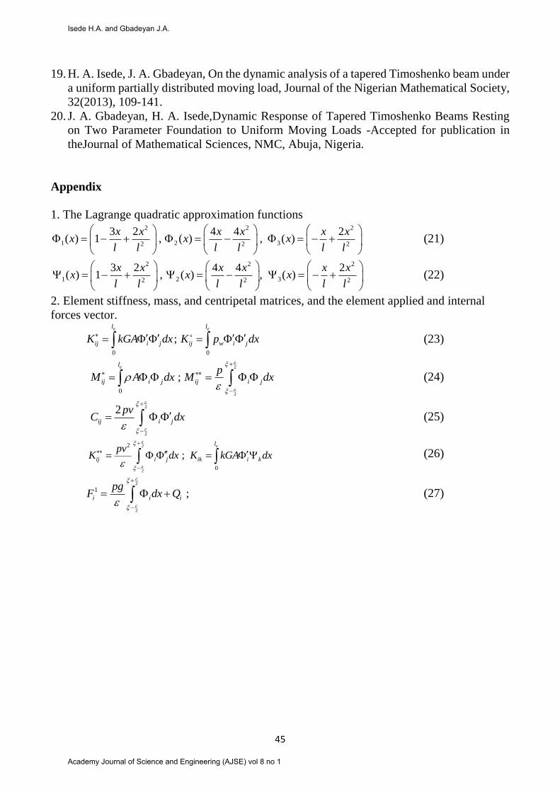
Appendix
1. The Lagrange quadratic approximation functions 2 2 2
1 2 32 2 2
3 2 4 4 2( ) 1 , ( ) , ( )
x x x x x xx x x
l l l l l l
(21)
2 2 2
1 2 32 2 2
3 2 4 4 2( ) 1 , ( ) , ( )
x x x x x xx x x
l l l l l l
(22)
2. Element stiffness, mass, and centripetal matrices, and the element applied and internal
forces vector.
0 0
;e el l
ij i j ij w i jK kGA dx K p dx (23)
2
20
;el
ij i j ij i j
pM A dx M dx
(24)
2
2
2ij i j
pvC dx
(25)
2
2
2
0
;el
ij i j ik i k
pvK dx K kGA dx
(26)
2
2
1 ;i i i
pgF dx Q
(27)
Isede H.A. and Gbadeyan J.A.
Academy Journal of Science and Engineering (AJSE) vol 8 no 1