dynamics of autodyne response formation in microwave...
TRANSCRIPT

Dynamics of Autodyne Response Formation
in Microwave Generators1
V. Ya. Noskov and K. A. Ignatkov
Ural Federal University, Yekaterinburg, Russia
Received in final form April 3, 2013
Abstract—The paper presents results of studying the dynamics of autodyne response formation when
switching on a radio-pulse microwave generator which is subject to the influence of its own reflection
radiation. Basic relations for a step-wise calculation of autodyne response as a function of time delay,
autodyne response time constant, distortion parameter and intrinsic parameters of the self-oscillating
system are obtained. Calculation and analysis of peculiarities of autodyne signal generation by
radio-pulse oscillator are conducted for the cases of motionless and moving reflecting object under
relatively low, medium and high inertia properties of the oscillator if compared to the propagation time of
the reflected radiation. Experimental research results that confirm conclusions of theoretical analysis are
obtained for a common hybrid-integrated autodyne TIGEL-08 module of the 8-mm frequency-range
implemented on a planar two-meza Gunn diodes and the same module stabilized by the external high-Q
resonator.
DOI: 10.3103/S0735272713050026
Radio-engineering systems that use autodyne principle have a simple structure of transceiving module
which contains only single antenna and autodyne oscillator (a.k.a. autodyne) combining functions of
receiver and transmitter. Hence autodynes are attractive to a wide range of applications including various
purpose short-range radars (SRR), equipment for controlling parameters of technological processes,
radio-spectroscopy, communications and measuring equipment where the mentioned quality indicators are
of essential importance [1–5].
The operation principle of these devices is based on autodyne effect that consists in changes of
auto-generator’s oscillation parameters, such as amplitude and frequency as well as auto-bias voltage,
caused by the impact of its own reflected radiation. Any of the mentioned low-frequency components of
autodyne response may be used as a useful signal given the possibility to extract them in a number of
different ways [1, 4–6].
The use of pulse modulation of autodyne probing signal significantly broadens functional capabilities of
systems as well as improves their parameters and characteristics [7].
Consider a case when the delay of the reflected from the target signal � is less than the radio-pulse
duration tp (� � tp ), so reception takes place simultaneously with the probing pulse transmission. In this case
radiated and reflected oscillations are coherent and the process of extracting useful signal is based on
registering changes in their interference picture inside the oscillator itself, i.e. on the autodyne effect.
Given the condition � > pt radiated and reflected radio-pulses do not overlap in time, hence during
reception of reflected probing pulse there is no output autodyne signal.
The mentioned property of autodynes provides improvement of a system’s interference immunity as well
as possibilities to define the far border of target discovery based on distance, register appearance of moving
targets in the observation region, measure their velocity and estimate range to a single target. Besides
discontinuous nature of oscillator’s operation improves stealthiness of autodyne radar and essentially
decreases energy consumption.
227
ISSN 0735-2727, Radioelectronics and Communications Systems, 2013, Vol. 56, No. 5, pp. 227–242. © Allerton Press, Inc., 2013.
Original Russian Text © V.Ya. Noskov, K.A. Ignatkov, 2013, published in Izv. Vyssh. Uchebn. Zaved., Radioelektron., 2013, Vol. 56, No. 5, pp. 21–41.
1Work was performed under financial support of Ministry of eduction and science of Russian Federation according to state
resolution No. 218 dated 09.04.2010.
Due to the mentioned properties of autodynes this kind of modulation is widely used in radio controlled
fuses, vehicle collision preventing systems, media separation border detectors, radio-wave security sensors
and many other systems. That is why numerous domestic and foreign authors dedicate their papers to
autodynes (one may check out the references of [8]).
When analyzing operation of these devices it was initially assumed that formation of autodyne effect in
auto-oscillator takes place upon arrival of reflected radio-pulse front, while the generated output
low-frequency signal, considering linear and uniform movement of the target, is harmonic like in homodyne
systems [7, 9–12].
Further research proved that this assumption holds true for systems that operate in decimeter and the
long-wave part of centimeter frequency band. However the accepted model gives no explanation to signal
distortions discovered in autodyne SRR of millimeter frequency band [13, 14], which, as shown in later
papers [15, 16], are caused by non-linear nature of reflected wave phase shift due to autodyne changes of
oscillation frequency.
A more complex model that accounts for the mentioned phenomena, is considered in [17, 18] when
analyzing autodyne effect in radio-pulse generators, including those with additional frequency modulation.
In these papers authors use the step method when solving autodyne equations to demonstrate that the process
of formation of instantaneous autodyne response values that depend on the distortion parameter is
accompanied by periodic amplitude and frequency leaps, which essentially increase the whole process
duration.
Using this model a connection between non-linear signal distortions and the process of autodyne
response formation was revealed [19] and studied to understand the influence of generator’s temperature
phase shift caused by self-heating of an active element (AE) during radio-pulse generation on parameters of
output signals [20]. Besides peculiarities of extracting and processing weak autodyne signals in the
generator’s power supply path on the background of modulating pulse were analyzed. Results of the
mentioned research are specified in the overview [8].
However the results obtained in these papers using quasi-static method to solve differential equations
hold true only for the case when intrinsic inertia of autodyne generator has negligibly small influence on the
process of autodyne response formation.
When using autodyne generators with high-quality oscillating system in radio-pulse SRR to adequately
describe the process of autodyne response formation one should account for inertial properties of the
generator. However this problem has not been addressed in literature available to the authors, though in
order to understand the physical nature of autodyne operation in such conditions not mentioning parameters
determination and correct application the problem demands a solution.
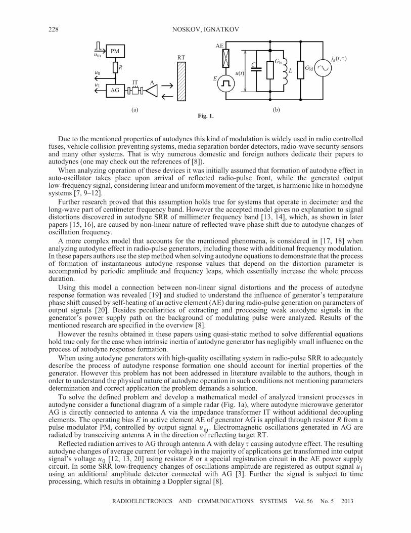
To solve the defined problem and develop a mathematical model of analyzed transient processes in
autodyne consider a functional diagram of a simple radar (Fig. 1à), where autodyne microwave generator
AG is directly connected to antenna À via the impedance transformer IT without additional decoupling
elements. The operating bias Å in active element AE of generator AG is applied through resistor R from a
pulse modulator PM, controlled by output signal um . Electromagnetic oscillations generated in AG are
radiated by transceiving antenna À in the direction of reflecting target RT.
Reflected radiation arrives to AG through antenna A with delay � causing autodyne effect. The resulting
autodyne changes of average current (or voltage) in the majority of applications get transformed into output
signal’s voltage u0 [12, 13, 20] using resistor R or a special registration circuit in the AE power supply
circuit. In some SRR low-frequency changes of oscillations amplitude are registered as output signal u1
using an additional amplitude detector connected with AG [3]. Further the signal is subject to time
processing, which results in obtaining a Doppler signal [8].
RADIOELECTRONICS AND COMMUNICATIONS SYSTEMS Vol. 56 No. 5 2013
228 NOSKOV, IGNATKOV
(a) (b)
Fig. 1.
PMum
u0
u1
AG
R
IT A
RT
AE
Å
u(t)
CGls
GldL
j ts( , )�

Let’s consider processes in autodyne generator without accounting for the influence of AE bias and
detection circuits.
A simple equivalent electrical circuit of autodyne microwave generator is depicted in Fig. 1b. A resonant
oscillating system is represented by a parallel oscillatory circuit that contains capacity C , inductance L and
intrinsic loss conductivity G ls . Load conductivity G Y kld 0 IT� , where Y0 denotes transmission line
conductivity and k IT stands for IT transmission coefficient, and a current source j j ts s� ( , )� are connected
to the oscillatory circuit in parallel. The latter element emulates impact of generator’s own reflected
radiation that arrives to it with delay�. N-type non-linear AE (for example, Gunn diode) is also connected in
parallel to the oscillatory circuit.
Considering relatively high value of loaded quality-factor Q C Gld s�� / of the oscillatory circuit where
G G G� �ls ld and �s
1/2�
�
( )LC , we assume that oscillations in AE are quasi-harmonic:
u t A t( ) = Re[ j ( ))]exp( ,
where ( )t t� �� 0 denotes total phase of oscillations; A A t� ( ), � ( )t stand for slowly changing
amplitude and phase at the current instant t. The average for the oscillations period “electronic” conductivity
of AEYe in a general case is a complex value dependent on oscillations amplitude Aand current frequency�:
Y G B G A B Ae e e e e= j ( , ) j ( , )� � �� � ,
where Ge and Be are resistive and reactive AE conductivities respectively. Then oscillations of equivalent
current source j ts ( , )� with amplitude J ts ( ),� and total phase ( )t,� are also quasi-harmonic:
j t J t ts sRe[ ( ) j ( ))]( , ) , exp( ,� � �� .
Hence applying Kirchhoff laws (Fig. 1b) yields:
Re[ ] +Re[ ] = ( )e os s� � ,AY AY j t � , (1)
where Y Y G Qos os ld s s1+ j2� � �( ) [ ( ) / ]� � � � denotes complex conductivity of the oscillating system.
Applying Kurokawa method [21] to analysis of equation (1) and conducting linearization of the resulting
system of truncated equations in the stationary oscillation mode of autonomous generator given j ts ( ) = 0,�
and A A� 0,� �� 0, followed by several elementary transformations yields a system of differential equations
with delay argument for small relative variations of amplitude a A A A� �( ) /0 0 and frequency
� � � �� �( ) /0 0 of generator’s oscillations:
Q a
ta t
ld
s
d
d
= cos ( , )
�
� � � � �� � � , (2)
� �� � � �a t� �= sin ( , )� , (3)
where � � � �( 2 )( )e 0A G G A0 / / denotes the reduced slope of generator’s increment causing degree of
regeneration and stability of a limit cycle; � �os e stands for a parameter that determines non-isodrome
nature of generator [22], i.e. accounts for the influence of frequency variations on oscillations amplitude via
changes of resistive conductivity values of the oscillating system � �os os 0= ( 2 )( )0 / /G G� � and
electronic conductivity of AE �e = ( 2 )0 / G ( )e 0� �G / � ; � � � �( 2 )( )e 0A G B A0 / / represents a parameter
that defines non-isochronous nature of generator; � � �� �os e denotes generator’s frequency stability
parameter that accounts for frequency slope of reactive conductivities of the oscillating system
� � �os os 0= ( 2 )( )0 / /G B� � and AE � � �e e 0= ( 2 )( )0 / /G B� � , the physical meaning of the latter two
being loaded quality-factor of a single-contour oscillating system �os ld�Q and a quality-factor of
electronic conductivity of AE � e e�Q , respectively; � stands for a coefficient that characterizes radiation
fading during propagation from radar to the target and back together with energy loss upon reflection;
� � �( , ) ( ) ( , )t t t� – is the total phase shift of radiation during propagation to the target and back;
��Q Qld ext/ denotes equivalent efficiency of the oscillating system,Qext being its external quality-factor.
RADIOELECTRONICS AND COMMUNICATIONS SYSTEMS Vol. 56 No. 5 2013
DYNAMICS OF AUTODYNE RESPONSE FORMATION IN MICROWAVE GENERATORS 229

Given the considered single-contour oscillating system of generator where
� �os 0 os 0( 2 )( )� � � �/ /G G 0, parameter is mainly determined by the slope of AE resistive conductivity
on frequency: � e. In microwave generators of the centimeter frequency band this parameter is negligibly
small. However in the millimeter band and in generators stabilized by additional external resonator [22, 23],
accounting for parameter in the system of equations (2), (3) is essential for adequate description of
autodyne characteristics. Besides, due to inequality� �os e�� holding true for real microwave generators we
further assume � �Q ld .
As follows from equations (2), (3), the main inertia of autodyne system is connected to a change speed of
oscillation amplitude. Combining these expressions and canceling variable � yields a differential equation
for normalized relative autodyne amplitude changes a t a t Kn n n a( ) = ( ) / � given by
d ( )
d
( ) = cos[ ( ) ]n n
n an
n n
an
n
a t
ta t t� �
1 1
� �
� � , (4)
where K a 1� � �� � � ��( ) / ( )/2 1 2
1 denotes autodyne gain of signal reflected from the target; t tn � / � and
� � �an a� / stand for normalized with respect to � current time and time constant of autodyne response
respectively; � �� � �a n ( )� �Q / 0 1 represents characteristic time constant of autodyne response that in
contrast to formula (10) in [14] also accounts for both non-isochronism � � �� / and non-isodromism
� � / Q ld coefficients of the microwave generator; � ��arctan( ) denotes phase shift angle of autodyne
amplitude changes.
Let’s use a well-known step method to solve the obtained system of equations (2), (3). This method was
first applied to autodynes in [8, 17–19]. According to the method let’s write down a sequence of main
relations for a step-wise phase calculation �( )nt of autodyne response, normalized relative autodyne
amplitude a tn n( ) and frequency � �n n n a( ) = ( ) /t t L� changes, where L Qa ld1� � �� � ��( ) / ( )/2 1 2
1
denotes coefficient of autodyne frequency deviation.
In addition let’s obtain expressions for absolute values of generation frequency �( )nt , as well as initial
and stabilized values of the mentioned variables at each step in the process of autodyne response formation
after the generator is turned on. We assume � � ��( , ) =t , which holds true for real operating conditions of
autodyne SRR including those of the millimeter frequency band [16].
STEP 0
This step corresponds to the normalized time interval tn
(0)(0,1)� from the instant the generator is turned
on ( )n
(0)t �0 to arrival of first reflected radiation ( )n
(0)t �1 . On this time interval we observe autonomous
oscillations mode when �( ) = 0n
(0)t , a tn n
(0)( ) = 0, � n n
(0)( ) = 0t , � �( ) =n
(0)
0t , i.e. there is no autodyne
response. Here and further on indexes in the tn superscript denote the step number.
STEP 1
Upon arrival of first reflected radiation whose oscillations correspond to autonomous generation mode
the phase shift � � �( , ) = ( )n
(1)t t is observed on the interval tn
(1)(1,2)� :
� � � � �( ) = ( )n
(1)
n
(0)t t � 0 . (5)
A general solution of heterogeneous equation (4) considering (5) using Euler method in the Cauchy form
is given by
a tt
t
n n
(1) n
(1)
an an
( ) = expd
cos(
n
(1)
�
�
�
�
�
�
�
�
�
�
�
�� �
�
0
0
1� �
�
�
�
�
�
�
�
�
�
�
�
�
�
��) exp d d
an
n
(1)
n
(1)n
(1)
n
(1)
1
00
t t C
tt
!
"
"
"
#
$
%
%
%
, (6)
RADIOELECTRONICS AND COMMUNICATIONS SYSTEMS Vol. 56 No. 5 2013
230 NOSKOV, IGNATKOV
where integration limits are determined by normalized duration of the step (from 0 to 1), Ñ denotes
integration constant.
Solving equation (6) considering zero initial conditions Ñ a t� ( ) = 0n0
(1)when tn
(1)�0 yields expressions
for normalized autodyne changes of oscillations amplitude for step 1 given by
a t K t tn n
(1)
a n
(1)
n
(1)( ) = ( )cos[ ( ) ]� �� = ( )cos( )a n
(1)
nK t 2&� �� , (7)
where K t ta n
(1)
n
(1)
an( ) 1 exp( )� � � / � denotes the dependent on time tn
(1)normalized autodyne gain.
Substituting (7) into (3) followed by several elementary transformations results in expression for relative
� �n n
(1)
n
(1)
a( ) = ( ) /t t L� and absolute �( )n
(1)t changes of oscillations frequency:
� � 'n n
(1)
a n
(1)
n
(1)
n
(1)( ) ( ) sin[ ( ) ( )]t L t t t� � � � � �L t ta n
(1)
n n
(1)( ) sin[ ( )]2&� ' , (8)
� � � �( ) ( )n
(1)
a n n
(1)t tm� �0 , (9)
where
L tt t
a n
(1) n
(1)
an
2 2
n
(1)
( ) =[1 exp( )] + [1 exp(� � � ��� � � �/ / an
2)]
12
� �
denotes the dependent on time tn
(1)normalized coefficient of autodyne frequency deviation;
' �
�
�� �
( ) arctanexp( )
exp(
n
(1) n
(1)
an
n
(1)
a
tt
t
�
� �
� �
1
1
/
/ n )
stands for the dependent on time tn
(1)phase shift angle of autodyne frequency changes, ( �� �m La a� 0
stands for frequency deviation of autodyne oscillations.
Upon arrival of first reflected radiation at time ( )n
(1)t �0 the value of � n n
(1)( )t equals
� �n n0
(1)
n n0
(1)( ) ( )t t� � � � �[( ) / ( ) ]sin( n1 1 2
2 1 2�� � &�
/). (10)
Stabilized values at step 1 �( )n
(1)t
), a tn n
(1)( )
), and � n n
(1)( )t
), obtained from (4), (7) and (8) given tn
(1)� ),
have the following corresponding values:
� &�( ) =n
(1)
nt)
2 ,
a tn n
(1)
n( ) = cos( ))
�2&� � ,
� &� 'n n
(1)
n( ) sin( )t)
� � �2 . (11)
STEP 2
Based on (8), (9) the changed at step 1 oscillations after delay � impact the generator on the time interval
tn
(2)(2,3)� with the phase shift � � �( , ) = ( )n
(2)t t :
RADIOELECTRONICS AND COMMUNICATIONS SYSTEMS Vol. 56 No. 5 2013
DYNAMICS OF AUTODYNE RESPONSE FORMATION IN MICROWAVE GENERATORS 231

� � � &� �( ) ( ) ( )n
(2)
n
(1)
n a n n
(1)t t p t� � �2 , (12)
where p ma a� (� � denotes autodyne response distortions parameter [15, 16] with modulation index
physical meaning.
Considering (12) differential equation (4) for normalized relative autodyne amplitude changes a tn n
(2)( )
is given by
d ( )
d
( )n n
(2)
n
(2)an
n n
(2)a t
t
a t�
1
�
= cos[ ( )]
an
n a n n
(1)12
�
&� � �� � p t . (13)
Approximate solution of equation (13) when accounting for negligibly small changes of� n n
(1)( )t during
time � and initial conditions a t a tn n0
(2)
n n1
(1)( ) = ( )
)
according to (11) for tn
(1)�1is given by
a t p tn n
(2)
n a n n
(1)( ) = cos[ ( )]2&� � �� �
� �
�
�
�
�
�
�
�
�� � � �
�
exp cos( ) cosn0
(2)
an
n n a
t
p�
&� � &� �
��
2 21
1
22
�
�
�
�
�
�
�
�
�
!
"
"
#
$
%
%�
&�sin( n ) . (14)
Substitution of (14) into (3) followed by a series of elementary transformations yields expressions for
relative � n n
(2)( )t and absolute �( )n
(2)t changes of oscillations frequency:
* +�
��
�
&� �n n
(2)
n a n n
(1)( )
( )sin ( )t p t� �
�
�
�
1
1
22
, -�
�
�
� ��
�
�
&� � �
1
1
2
2
2cos ( )n a n n
(1)p t
�
�
�
�
�
�
�
�
�
�
�
�
� � ��
�
��
&� � &�
1
1
2 2
2
2exp cos( ) cos
n
(2)
an
n n
t�
��
�
&��
�
�
�
�
�
�
�
�
�
�
!
"
"
#
$
%
%
pa nsin1
1
22
, (15)
� � � �( ) ( )n
(2)
a n n
(2)t tm� �0 ( . (16)
Initial values of �( )n0
(2)t , a tn n0
(2)( ), and � n n0
(2)( )t upon arrival of second reflected radiation, obtained from
(12), (14), (15) when tn
(2)�0 are given by
� &�
��
�
&�( )
( )
sin(n0
(2)
n a nt p� �
�
�
!
"
"
#
$
%
%
21
1
22 1 2/
), (17)
a tn n0
(2)
n( ) = cos( )2&� �� , (18)
�
��
�
n n0
(2)( )
( )t � �
�
�
1
12
sin sin(n a n21
1
22
&�
��
�
&��
�
�
�
�
�
�
�
�
�
�p ) �
�
�
��
�
�
&� �
1
1
2
2
2cos( )n . (19)
RADIOELECTRONICS AND COMMUNICATIONS SYSTEMS Vol. 56 No. 5 2013
232 NOSKOV, IGNATKOV

Stabilized values of�( )n
(2)t
), a tn n
(2)( )
), and� n n
(2)( )t
), obtained for the case tn
(2)� ), at step 2 are given by
� &� &� '( ) sin( )n
(2)
n a nt p)
� � �2 2 , (20)
a t pn n
(2)
n a n( ) = cos[ sin( )])
� � �2 2&� � &� ' , (21)
� &� ' &� 'n n
(2)
n a n( ) sin[ + sin( )]t p)
� � � �2 2 . (22)
STEP 3
Based on (15), (16) the changed at step 2 oscillations after delay � impact the generator on third time
interval tn
(3)(3, 4)� with the phase shift � � �( , ) = ( )n
(3)t t :
� � � &� �( ) ( ) ( )n
(3)
n
(2)
n a n n
(2)t t p t� � �2 . (23)
Approximate solution of equation (4) for autodyne amplitude changes a tn n
(3)( ) considering (23),
negligibly small; changes of� n n
(2)( )t during time � and initial conditions a t a tn n0
(3)
n n1
(2)( ) = ( )
)
when tn0
(3)�0
and tn
(2)�1is given by
, -a t p tn n
(3)
n a n n
(2)( ) = cos ( )2&� � �� �
� �
�
�
�
�
�
�
�
�
� �exp cos{2 sin[2 + ]}n
(3)
an
n a n
tp
�
&� � &� ' � �
�
�
�
�
�
�
�
�
expn
(3)
an
t
�
. � �
�
�
�
�
�
�
�
cos( )
sin sinn a n a n21
1
21
1
22 2
&� �
��
�
&�
��
�
&�p p�
�
�
�
�
��
�
�
�
!
"
"
#
$
%
%
/
0
1
21
3
4
1
51
�
�
�
&� �
1
1
2
2
2cos( )n . (24)
Substitution of (24) into (3) yields expressions for relative � n n
(3)( )t and absolute �( )n
(3)t changes of
oscillations frequency:
�
��
�
&� �n n
(3)
n a n n
(2)( )
( )sin[ ( )]t p t� �
�
�
�
1
1
22
�
�
�
�
�
�
1
1
2
2a tn n
(3)( ), (25)
� � � �( ) ( )n
(3)
a n n
(3)t tm� �0 ( . (26)
As follows from (23)–(25), given tn
(3)�0 and tn
(3)� ), we obtain initial �( )
n0
(3)t , a tn n0
(3)( ), � n n0
(3)( )t and
stabilized �( )n
(3)t
), a tn n
(3)( )
), � n n
(3)( )t
)values of phase �( )n
(3)t and relative autodyne amplitude a tn n
(3)( ) and
frequency � n n
(3)( )t changes:
� &� �( ) ( )n0
(3)
n a n n0
(2)t p t� �2 , (27)
RADIOELECTRONICS AND COMMUNICATIONS SYSTEMS Vol. 56 No. 5 2013
DYNAMICS OF AUTODYNE RESPONSE FORMATION IN MICROWAVE GENERATORS 233
a t tn n0
(3)
n0
(3)( ) = cos[ ( ) ]� �� = cos[ sin( )]n a n2 2&� � &� '� � �p , (28)
� n n0
(3)( )t � �
�
�
�
�
�
( )sin ( ) ( )
n0
(3)
n n0
(3)1
1
1
12
2
2
��
�
� �
�
�
t a t , (29)
� &� �( ) ( )n
(3)
n a n n
(2)t p t
) )� �2 � � � � �2 2 2&� &� ' &� 'n a n a nsin[ sin( )]p p , (30)
a t tn n
(3)
n
(3)
n( ) = cos[ ( ) ] cos) )
� � 6 �� � &� �2 � � � 7p pa n a nsin[ + sin( )]{ }2 2&� ' &� ' , (31)
� � ' &� 'n n
(3)
n
(3)
n( ) = sin[ ( ) ] = sint t) )
� 6 �2 � � � 7p pa n a nsin[ + sin( )]{ }2 2&� ' &� ' . (32)
STEP n
Analysis of the presented solutions allowed finding common expressions for calculating the values of
interest at nth step using a solution obtained at an earlier step ( )n �1 . In a general case the result of impact of
( )n �1 reflected radiation on the analyzed process of automatic oscillations at nth step is given by
� � � &� �( ) ( ) ( )n
( )
n
( )
n a n n
( )t t p t
n n n� � �
� �1 12 , (33)
a t t tn n n
n n
( )
n
( )
n
( )
an( ) = cos[ ( ) ] exp( )� � �� � � / { ( ) cos[ ( ) ]}n n1
( 1)
n0
( 1)a t t
n n� �
� �� � , (34)
� n n
( )( )t
n� �
�
�
�
�
�
( )sin ( ) ( )n
( )
n n
( )1
1
1
12
2
2
��
�
� �
�
�
t a tn n
, (35)
� � � �( ) ( )n
( )
a n n
( )t t
n
m
n� �0 ( , (36)
� &� �( ) ( )n
( )
n a n n
( )t p t
n n
) )
�
� �21
, (37)
a t tn n
n n
( )
n
( )( ) = cos[ ( ) ]
) )�� � , (38)
� � 'n n
( )
n
( )( ) = sin[ ( ) ]t t
n n
) )� . (39)
Analyzing (33)–(39) reveals that amplitude a tn
n n
( )( ) and frequency � n n
( )( )t
nchange laws after turning
on the generator at nth step are determined by a phase shift �( )n
( )t
nof reflected wave during time � on
frequency�( )n
( )t
n�1of ( )n �1 th step. When calculating a t
n
n n
( )( ) according to (34) one should account for end
values of a tn
n n
( 1)( )
�
when tn
n
( 1)=1
�
and initial values of phase �( )n0
( 1)t
n�when t
n
n
( 1)= 0
�
at ( )n �1 th step.
We should note that the obtained expressions for stabilized values of �( )n
( )t
n
), a t
n
n n
( )( )
), and � n n
( )( )t
n
)at
step n according to (37)–(39) coincide with quasi-static solutions obtained in [8, 19], while the solution
finding procedure for stabilized values corresponds to the solution order of transcendent equations of nth
approximation that describe response of autodyne that operates in continuous radiation mode [16, 22].
For further analysis of the obtained expressions (5)–(39) that describe stabilization dynamics of
radio-pulse generator’s autodyne response we use numerical methods implemented in MathCAD software
package. First let’s consider the case of motionless target when the time delay � in the presented expressions
is fixed followed by the case of moving target when � is variable.
RADIOELECTRONICS AND COMMUNICATIONS SYSTEMS Vol. 56 No. 5 2013
234 NOSKOV, IGNATKOV

For the first case graphs of stabilized instantaneous phase �( )n values, normalized relative amplitude
a nn ( ) and frequency � n ( )n for various initial values of normalized with respect to oscillation period
� � � 8* &n 0� 2 ) are depicted in Fig. 2. Curve numbers in Fig. 2 have the following correspondence to � n
values: 1 —� n �0.15; 2 —� n �0.35; 3 —� n �0.6; 4 —� n �0.75. The graphs were calculated for pa �0.8,
� �1, and � � –0.22, as well as various values of normalized time constant for autodyne response: � an � 0.1
(Fig. 2à), � an � 1.0 (Fig. 2b) and � an � 10 (Fig. 2c).
Horizontal axis represents sequence numbers n of partial reflections (step numbers) of electromagnetic
radiation after switching on the generator. A time interval with duration � whose boundaries lie within
n t n� �< <( 1)� corresponds to each nth step. The corresponding time interval with number n is further
referred to as the “impact region of nth reflection”.
RADIOELECTRONICS AND COMMUNICATIONS SYSTEMS Vol. 56 No. 5 2013
DYNAMICS OF AUTODYNE RESPONSE FORMATION IN MICROWAVE GENERATORS 235
(a) (b) (c)
Fig. 2.
�( )n
0
& / 2
&
3 2& / 3 2& /
&
& / 2
0
�( )n
3 2& /
&
& / 2
0
�( )n
0.5
0
–0.5
–1
a n1n ( )
�n ( )n
0 2 4 6 8 n 0 2 4 6 8 n 0 2 4 6 8 n
a n1n ( ) a n1n ( )
0.5
0
–0.5
–1
0.5
0
–0.5
–1
�n ( )n �n ( )n
0 2 4 6 8 n 0 2 4 6 8 n 0 2 4 6 8 n
0 2 4 6 8 n 0 2 4 6 8 n 0 2 4 6 8 n
–1
–0.5
0
0.5
–1
–0.5
0
0.5
–1
–0.5
0
0.5
1
2
4
3 3
4
2
1 1
2
4
3
1
2
3
4
2
4
3
1 1
3
4
2
3
4
2
1
3
4
2
1
3
4
1
2
2Values of coefficients � and � used in calculations are close to those obtained experimentally in [22] for hybrid-autodyne
“Tigel-08” modules of the 8-mm frequency band implemented on planar two-meza Gunn diodes.

For the second case of moving target families of phase (PAC) � �( )
n
n( ), amplitude (AAC) a
n
n
( )
n( )� and
frequency (FAC)� �n
( )
n
n( ) autodyne characteristics are depicted in Fig. 3 as functions of time normalized by
oscillations period � n , for the first three steps (n = 1, 2, 3). Calculations were made given � �1, � � –0.2 for
the following variations of distortions parameter pa and normalized time constant of autodyne response
� an : pa � 0.8,� an �0.1 (Fig. 3à); pa �0.8,� an �3 (Fig. 3b); pa �2.5,� an �0.1 (Fig. 3c); pa �2.5,� an �3
(Fig. 3d). Instant value in the middle of the analyzed intervals when � n � 0.5 were recorded.
As follows from Fig. 2 in absence of reflected radiation (step 0) there is no autodyne response:
a t an 0 1( ) ( ) = 0� 0 , � �n 0 n( ) ( ) = 0t � 0 . Consequently generation frequency equals � � �( ) ( ) =0t � 0 0.
Hence at step 1 upon arrival of first reflected radiation phase� �( ) ( )n
(1)t � 1 does not change and is determined
by relative location of motionless target, i.e. the value of delay � n .
At this step according to the phase shift �( )1 we observe first formation of autodyne response which
results in exponentially increasing amplitude changes a t an n
(1)
n( ) (1)� and oscillations frequency changes
� �n n
(1)
n( ) ( )t � 1 that follows a more complex law.
Frequency changes at step 1 cause phase changes at the following step� �( ) (2)n
(2)t � that act as a delayed
feedback “generator–target” channel in autodyne system and are directed at new partial changes of
amplitude a t an n
(2)
n( ) (2)� and frequency � �n n
(2)
n( ) (2)t � .
Further step-wise autodyne response formation takes place in a similar way when following partial
responses a nn ( ) and � n ( )n depend on the previous ones a nn ( )�1 and � n ( )n �1 .
As follows from the graphs � n ( )n , intrinsic leap frequency changes � n ( )1 caused by the impact of
reflected wave get mixed with additional exponential changes that appear due to non-isochronism of
generator ( )� 9 0 and are caused by inertial changes of oscillations amplitude an (1). The general picture of
the obtained graphs for amplitude changes a nn ( ) differs from a similar picture obtained as a result of
quasi-static calculation [4, 19] by smoothness of processes at region boundaries caused by inertial nature of
amplitude changes stabilization a nn ( ) since frequency � n ( )n and phase �( )n changes at region boundaries
occur in leaps, while under some phase values�( )n
( )t
nthe leap has a shape of a tooth (curves 1 in Fig. 2à and
Fig. 2b).
As demonstrated in [4, 19], on some value intervals of phase �( )n
( )t
n, where FAC derivative
d ( ) / dn n
( )
n� �tn
�0, the “generator–target” system has positive feedback channel that stimulates further
increase of autodyne frequency changes. Hence on these intervals of phase�( )n
( )t
nvalues, like in quasi-static
analysis [4, 19], we observe relaxation process of autodyne response stabilization (curves 1, 3 and 4 in
Fig. 2). On FAC segment where d ( ) / dn n
( )
n� �tn
� 0, the system has delayed negative feedback causing
opposite changes at the next step. In this case we observe step-wise aperiodic law of autodyne response
stabilization (curves 2, Fig. 2).
The feedback relation depth and, correspondingly, the duration of stabilization process in general
(number n) and its character also depend on intrinsic parameters of generator, namely non-isochronism � and
non-isodromism�. Calculations indicate that for isochronous and isodrome generator ( = = 0)� � the graphs
of step-wise changes �( )n and � n ( )n become step-wise without exponential component, while the
stabilization process durations becomes essentially smaller that in the case of non-isochronous generator.
At this point we should define the notion of autodyne response stabilization duration. We define
stabilized process as a one whose instantaneous low-frequency autodyne response values reach a state when
further partial impacts of reflected radiation do not cause an amplitude change by the specified factor, for
example, a factor of 0.1.
As a measure of duration for such a process when � an ��1, we use a number of partial reflections nst , i.e.
the needed number of stabilization steps n. As follows from comparison of graphs in Fig. 2à–c, in this case
inertia of amplitude changes only smoothens the response a nn ( ) at the boundaries of reflected radiation
impact regions. In this case distortion parameter pa has the major impact on the duration of autodyne
response stabilization.
For example, when pa �0.1 autodyne response reaches its final state practically upon the first impact of
reflected radiation ( )stn �1 . Greater values of this parameter cause greater numbers of steps nst . For
example, when pa � 0.8 this process ends at step 9…10, while given pa �1 it is infinite like non-fading
oscillations.
RADIOELECTRONICS AND COMMUNICATIONS SYSTEMS Vol. 56 No. 5 2013
236 NOSKOV, IGNATKOV

When pa > 1 the relaxation processes under certain phase values follow with increasing amplitude when
increasing the number of partial reflections form the target. In the case of “inertial” autodyne when
inequality� an ��1holds true, in the process of autodyne response stabilization the amplitude changes a nn ( )
get smoothed and the duration of transient process is fully determined by absolute value of autodyne
response time constant � a .
RADIOELECTRONICS AND COMMUNICATIONS SYSTEMS Vol. 56 No. 5 2013
DYNAMICS OF AUTODYNE RESPONSE FORMATION IN MICROWAVE GENERATORS 237
(a) (b) (c) (d)
Fig. 3.
0 1 � n 0 1 � n 0 1 � n 0 1 � n
2&
0
&
�(
)1
2&
0
&
2&
0
&
2&
0
&
�(
)1
�(
)1
�(
)1
0 1 � n 0 1 � n 0 1 � n 0 1 � n
0 1 � n 0 1 � n 0 1 � n 0 1 � n
0 1 � n 0 1 � n 0 1 � n 0 1 � n
0 1 � n 0 1 � n 0 1 � n 0 1 � n
0 1 � n 0 1 � n 0 1 � n 0 1 � n
0 1 � n 0 1 � n 0 1 � n 0 1 � n
0 1 � n 0 1 � n 0 1 � n 0 1 � n
0 1 � n 0 1 � n 0 1 � n 0 1 � n
0
–1
1
1
–1
0
0
–1
1
1
–1
0
0
–1
1
1
–1
0
0
–1
1
1
–1
0
an
()
1�
n(
)1
an
()
1
an
()
1
an
()
1
�n
()
1
�n
()
1
�n
()
1
�n
()
2a
n(
)2
0
–1
1
1
–1
0
�(
)2
&
0
2&
�n
()
2a
n(
)2
0
–1
1
1
–1
0
�(
)2
&
0
2&
�n
()
2a
n(
)2
0
–1
1
1
–1
0
�(
)2
&
0
2&
�n
()
2a
n(
)2
0
–1
1
1
–1
0
�(
)2
&
0
2&
2&
0
&
�(
)3
0
–1
1
1
–1
0
an
()
3�
n(
)3
2&
0
&
�(
)3
0
–1
1
1
–1
0
an
()
3�
n(
)3
2&
0
&
�(
)3
0
–1
1
1
–1
0
an
()
3�
n(
)3
2&
0
&
�(
)3
0
–1
1
1
–1
0
an
()
3�
n(
)3

Let’s consider peculiarities of forming autodyne response of radio-pulse autodyne in different impact
regions of reflected radiation from the target (Fig. 3). Considering the obtained characteristics that upon first
impact of reflected radiation, when it corresponds to stationary oscillation mode of generator, PAC is linear:
� &�(1)
n�2 (graphs in row 1). Hence AAC an
( )1and FAC � n
( )1have the shape of harmonic functions of
normalized time � n (graphs in rows 2 and 3).
In this case increases of instantaneous oscillations frequency cause corresponding changes in phase shift
at step 2 �(2)
, while its decreases facilitate slowdown of this process (graphs in row 4). Hence frequency
changes caused by the first impact of reflected radiation at step 2 cause “deformation” of PAC �(2)
and,
correspondingly, essential distortions of AAC an
(2)and FAC � n
(2)(graphs in rows 5 and 6). In this case one
FAC edge � n
(2)appears to be steeper (with positive derivative), while the second one is smoother.
These changes in FAC� n
(2)impact the PAC �
(3)at the next step, causing further increase of its slope on
the first interval and appearance of opposite concavity segment on the second (graphs in row 7). As follows
from the graphs of rows 8 and 9, these changes also impact the shape of AAC an
(3)and FAC� n
(3)in the third
impact region.
As follows from analysis of graphs in Fig. 3à, when inequality � an ��1(� �a �� ) holds true dynamics of
autodyne characteristics obtained in the present paper practically fully coincide with those calculated using
quasi-static model (Figs. 1, 2, [19]) and measured experimentally (Fig. 10, [19]). When this inequality is not
satisfied, dynamics of exponential AAC an
n
( )change in time is determined by time constant � a (Fig. 3b).
Hence in the latter case we observe a dependence of amplitude an
n
( )on both instant of signal registration in
the chosen interval of selection region and target velocity.
FAC � n
( )nin the beginning of the stabilization process possesses somewhat smaller amplitude of
autodyne frequency changes (due to smaller component caused by generator’s non-isochronism), than in the
previous case. Hence the observed in Fig. 3b autodyne response characteristics an
n
( )and � n
( )nhave smaller
distortion in the transient period, than when inequality � an ��1holds true.
Calculations of characteristics for further impacts (n � 4,...) of reflected radiation demonstrated that
under distortion parameter values pa �1(Fig. 3à, b) the considered process of step-wise autodyne response
formation ends with stabilized AAC and FAC shapes studied in [16, 22] for the case of continuous generator
operation.
When pa �1, autodyne characteristics �(1)
, an
( )1, and � n
( )1in the first reflection region (n = 1) have no
difference from the case when pa �1, i.e. PAC is linear, while AAC and FAC have sine shapes (Fig. 3c, d).
This means that in this impact region of autodyne system we observe linear formation of signals with
Doppler frequency like in homodyne radars. However in the case of “inertial” autodyne there exists some
loss in signal amplitude an
( )1(Fig. 3d). Further partial reflections (n > 1) cause essential complications of
autodyne characteristics due to strong phase modulation of radiation with loss of information component of
the output signals being the Doppler frequency. Their formation process that depends on inertial properties
of autodyne generator with increasing number of steps transitions into quasi-static one, which caused
destruction of output signal’s spectrum.
Let’s consider stabilization dynamics of relative autodyne changes of amplitude | |maxa An n� and
frequency | |max� n n� : . To calculate stabilization characteristics for these quantities according to the
developed methodology one should specify such values of normalized time � n along with intrinsic
generator’s parameters when the corresponding parameter has the maximum value. The conditions of
interest are determined from (37)–(39) for the stabilized values using roots of transcendent equations of nth
order for phase �( )n
(n)t
):
2 2 01
&� � ' &n a n n
( )( )� � � �
)
�
p tn
/ , (40)
2 01
&� � �n a n n
( )( )� � �
)
�
p tn
. (41)
Using the intersections method of iterative algorithm in MathCAD implemented using root( ) function,
we find roots of equations (40), (41), substituting which into expressions (5)–(39) yields the corresponding
RADIOELECTRONICS AND COMMUNICATIONS SYSTEMS Vol. 56 No. 5 2013
238 NOSKOV, IGNATKOV

step-wise dependencies A nn ( ) and : n ( )n . In Fig. 4à,b we depicted graphs of these dependencies calculated
for previous values of pa , �, and �, but under different values of normalized autodyne response time
constant: � an � 0.1 (curves 1), � an � 1.0 (curves 2), � an � 2.5 (curves 3), and � an � 10 (curves 4).
Comparison of graphs in Fig. 4à and curves 1 in Fig. 2 reveals that given small inertia of generator
( )� an ��1 amplitude value of autodyne response get stabilized without relaxation process and faster than
their instantaneous values. In other cases (� an ~ 1 and � an ��1), this difference is less noticeable, while
amplitude stabilization is practically monotonous.
We should note that in a hypothetical case of isochronous and isodrome generator ( )� �� �0 given the
value of distortion parameter ( pa �0.8) amplitude stabilization of frequency changes : n ( )n ends on step 2
despite the value of time constant � a . For real microwave generators ( , )� � 9 0 this process is essentially
longer and it determined by inertia of amplitude changes.
Experimental verification of the obtained results was conducted on a stand described in [8, 19]. Modified
hybrid-integral “Tigel-08M” modules of the 8-mm frequency band implemented on planar two-mezo Gunn
diodes were the targets of research.
These modified modules have a different topology of a diode insert if compared to the modules studied in
[8, 19]. The polycore substrate expects parallel (with respect to microwave frequency) insertion of two chips
with bias circuit decoupling into a notch resonator: planar Gunn diode and additional detector diode with
Schottky gate [24]. This allowed separating circuits of generator modulation and autodyne signal extraction
based on amplitude change.
First module used experiments is a standard one. Its autodyne response time constant measured using the
beat method [25], amounts to � a
91 1. 1� .( )
–� 3 0 s. To implement the case of “inertial” generator we used
the same “Tigel-08M” module, but it was stabilized according to “reflection-oriented” method with
high-quality resonator resistively connected with the main resonator of the generator. Equivalent
quality-factor of the oscillating system for the second module measured with the help of autodyne
characteristics amounted to nearly 1700 [24], while the autodyne response time constant equaled nearly
25 19
. 0–
s.
Autodyne response based on amplitude change was measured from detector output and was fed to
analogue signal processing unit (ASPU) that contains preliminary low-noise differential amplifier, pulse
spreading circuit (sample and hold) and main signal amplifier. Output signal from ASPU was further
digitized using NI-9205 module by National Instruments as part of DAQ-9172 platform. The digitized
signal was passed for processing by a virtual device implemented in LabView 8.6 software on a PC via a
USB cable.
Research of stabilization dynamics of autodyne response was conducted in the following conditions:
modulation period of radio-pulse autodyne of 10 µs; modulating pulse duration of 400 ns; duration of strobe
pulse that controls sample and hold circuit and discreteness of this pulse stabilization with respect to the
modulation pulse start of 10 ns.
Figure 5 depicts graphs of normalized dependences of autodyne signal amplitude A tn s( ) at ASPU output
on time position of the strobe pulse ts . Curves 1 and 2 are obtained for 1.5 m long waveguide between
generator and Doppler signal simulator, while curves 3 and 4 correspond to the 6 m long waveguide. In this
case reflected microwave radiation amplitude in the path was maintained using variable attenuator at the
level that provided the value of distortion parameter around 0.8. The value of this parameter was controlled
when switching the generator into continuous oscillations mode.
RADIOELECTRONICS AND COMMUNICATIONS SYSTEMS Vol. 56 No. 5 2013
DYNAMICS OF AUTODYNE RESPONSE FORMATION IN MICROWAVE GENERATORS 239
(a) (b)
Fig. 4.
0.2
0.4
0.6
0.8
An(n)
0 2 4 6 8 n 0 2 4 6 8 n
1 32
4 4
2
31
Xn(n)
0.2
0.4
0.6
0.8

For curves in Fig. 5 the following values of normalized autodyne response time constant� an and number
of partial reflections nst needed to drive signal’s amplitude A nn ( ) to 0.9 of its maximum value were
obtained:� an � 0.1, nst �2—curve 1; � an � 2.5, nst �6—curve 2; � an � 0.025, nst � 1.25—curve 3; � an �
0.625, nst � 2.25—curve 4. We should note that for curves 1, 2 the time intervals of impact regions equal
10 ns, while for curves 3, 4 they amount to 40 ns.
Comparison of experimental curves 1, 2 considering their correction by the time duration of the impact
region and the calculated curves 1, 3 respectively (Fig. 4à) reveals their good matching. Absence of step
nature in curve 1 (Fig. 5) is caused by operation principle of the sample and hold circuit, where the hold
capacitor fixes the input signal voltage that corresponds to the end of strobe pulse.
In Fig. 6 we depicted oscillograms and spectrograms of autodyne signals obtained using a standard
“Tigel-08M” module (Fig. 6à,b) and the same module stabilized by an external resonator (Fig. 6c). The
waveguide path length between generator and Doppler signal simulator was 6 m, the time position of the
strobe pulse was 160 ns (third impact region), Doppler frequency was around 2 kHz.
For the case depicted in Fig. 6à and Fig. 6b, the level of reflected radiation was chosen so as to provide
pa ;0.8 and pa �2 3... , respectively. The diagrams in Fig. 6c were obtained given the same level of reflected
radiation as in the case depicted in Fig. 6b.
Comparing the obtained diagrams in Fig. 6à,b we see that with increasing value of distortion parameter
( )pa �2 phase modulation of autodyne signal caused by the impact of reflected radiation leads to
disappearance of Doppler component of autodyne signal’s frequency (when n �1). In this case the signal
becomes “quasi-stationary” ([26]), while its spectrum gets decomposed into equidistant components. The
appearance of oscillogram in Fig. 6b qualitatively corresponds to the calculated time diagram of AAC an (3)
in third region (Fig. 3c).
The diagrams presented in Fig. 6c experimentally prove validity of recommendation [8, 19] regarding
reasonability of using an external resonator that improves signal spectrum and broadens the dynamic range
of SRR. We should note that under temporary movement of the strobe pulse to the side of decreasing time
delay ts the output signal’s amplitude becomes noticeably smaller according to curve 4 (Fig. 5), which is
caused by inertia of stabilized generator.
The considered above conditions of solving a number of practical problems or short-range radar possess
certain practical meaning, since when processing signals in SRR one should consider peculiarities pf
autodyne response formation. When distance between radio-pulse SRR and a target is sufficiently large and
the quality-factor Q ld of the oscillating system is relatively low, so that delay � is greater than characteristic
time � a of autodyne response stabilization ( )a� ��� , one may neglect inertia of amplitude changes when
analyzing peculiarities of autodyne response formation. The process of autodyne response formation in this
case may be described by the step method with precision sufficient for practice using expressions obtained
under quasi-static approximation [4, 19].
In the case of small distance between SRR and a target given high quality-factor Q ld of the oscillating
system the opposite is true: � ��� a . In this case autodyne response stabilization is fully determined by
characteristic time constant � a , while its analysis may be conducted using a system of common differential
equations where all variable are defined at the same time instant (refer to expressions (8), (9) in [14]).
The problem of analyzing dynamics of autodyne response formation when � and � a are comparable in a
general case may be solved using the methodology presented above.
RADIOELECTRONICS AND COMMUNICATIONS SYSTEMS Vol. 56 No. 5 2013
240 NOSKOV, IGNATKOV
Fig. 5.
42 3
1
0 40 80 120 160 ts, ns
An(ts)
0.8
0.6
0.4
0.2

We should note that as a result of analyzing transient processes in radio-pulse autodyne using quasi-static
method in [8, 19] a conclusion on resolvability of using an external high quality-factor resonator was made.
Such decision facilitates broadening the dynamic range of radio-pulse SRR as well as decreasing both
distortions in output signal and stabilization time of instant values of autodyne response.
However in this paper we revealed that increased equivalent quality-factor of the oscillating system make
the transient process longer, i.e. autodyne does not have enough time to reach to the following arriving pulse.
Hence this trade-off should be considered in SRR where the decision time on target presence is limited.
Thus, the conducted research on stabilization dynamics of autodyne response considering inertia of
amplitude changes essentially broadened the known facts on processes that take place in radio-pulse
microwave generators subject to influence of radiation reflected from the target mentioned in review [8].
Besides, the obtained results allowed demonstrating the reasons of quasi-chaos autodyne operation mode
studied earlier in a number of papers [27–29] for continuous operation mode, as well as finding a more
precise of the so-called “quasi-stationary” [26] autodyne operation mode, when Doppler frequency signal is
obtained on its output.
REFERENCES
1. I. V. Komarov, S. M. Smolskiy, Fundamentals of Short-Range FM Radar (Artech House, Norwood MA, 2003).
2. S. M. Smolskiy, M. K. Generalov, “Homodyne and autodyne configurations of short-range radar systems,” //
Telecommunication Sciences 1, No. 1, 14 (2010).
3. F. R. Pantoja, E. T. Calazans, “Theoretical and experimental studies of gain compression of millimeter-wave
self-oscillating mixers,” IEEE Trans. Microwave Theory Tech. MTT-33, No. 3, 181 (1985).
4. M. Krairiksh, W. Buasomboon, P. Ngamjanyaporn, C. Phongcharoenpanich, “Design of a spherical array
self-mixing oscillator antenna,” in Proc. APMC-2001, Taipei, Taiwan (Taipei, 2001), pp. 815–818.
5. S. A. Alidoost, R. Sadeghzade, R. Fatemi, “Autodyne system with a single antenna,” in Proc. 11th Int. Radar
Symp., IRS 2010, 16–18 June 2010, Vilnius, Lithuania (Vilnius, Geozondas LTD, 2010), Vol. 2, pp. 406–409.
6. S. D. Votoropin, V. Ya. Noskov, S. M. Smolskiy, “Modern hybrid-integral autodyne generators of microwave
and millimeter frequency bands and their applications. Part 3. Functional peculiarities of autodynes,” Uspekhi
Sovremennoi Radioelektroniki. Zarubezhnaya Radioelektronika, No. 11, 25 (2007).
7. S. D. Votoropin, V. Ya. Noskov, “Operation mode analysis of autodyne hybrid-integral UHF circuits
implemented on mezo-planar micro-powerful Gunn diodes,” Izv. Vyssh. Uchebn. Zaved., Fizika 45, No. 2, 88
(2002).
8. V. Ya. Noskov, S. Ì. Smolskiy, “Modern hybrid-integral autodyne generators of microwave and millimeter
frequency bands and their applications. Part 6. Studies of radio-pulse autodynes,” Uspekhi Sovremennoi
Radioelektroniki. Zarubezhnaya Radioelektronika, No. 6, 3 (2009).
9. T. Tetsuo, I. Akira, B. Kazuhiro, et al., “Radar sensor for automotive collision prevention,” IEEE MTT-S Int.
Microwave Symp. Dig., 168 (1978).
RADIOELECTRONICS AND COMMUNICATIONS SYSTEMS Vol. 56 No. 5 2013
DYNAMICS OF AUTODYNE RESPONSE FORMATION IN MICROWAVE GENERATORS 241
(a) (b) (c)
Fig. 6.

10. M. G. Somekh, W. Richmond, J. Moroz, M. T. Lazarus, “Development of pulsed self-oscillating mixer,”
Electron. Lett. 16, No. 15, 597 (1980).
11. P. À. Jefford, M. S. Howes, “Modulation schemes in low-cost microwave field sensor,” IEEE Trans. Microwave
Theory Tech. MTT–31, No. 8, 613 (1985).
12. G. P. Ermak, I. V. Popov, A. S. Vasilev, A. V. Varavin, V. Ya. Noskov, K. A. Ignatkov, “Radar sensors for hump
yard and rail crossing applications,” Telecom. and Radio Eng. 71, No. 6, 567 (2012).
13. M. J. Lazarus, F. P. Pantoja, M. Somekh, et al., “Nåw direction-of-motion Doppler detector,” Electron. Lett. 16,
No. 25, 953 (1980).
14. Ye. M. Gershenzon, B. N. Tumanov, V. Ò. Buzykin, et al., “Common characteristics and peculiarities of autodyne
effect in auto-generators,” Radiotekh. Elektron. 27, No. 1, 104 (1982).
15. S. D. Votoropin, N. M. Zakarlyuk, V. Ya. Noskov, S. M. Smolskiy, “On essential impossibility of autodyne
self-synchronization by radiation reflected from a moving target,” Izv. Vyssh. Uchebn. Zaved., Fizika 50, No. 9,
53 (2007).
16. S. D. Votoropin, V. Ya. Noskov, S. M. Smolskiy, “Modern hybrid-integral autodyne generators of microwave
and millimeter frequency bands and their applications. Part 2. Theoretical and experimental research,” Uspekhi
Sovremennoi Radioelektroniki. Zarubezhnaya Radioelektronika, No. 7, 3 (2007).
17. S. D.Votoropin, V. Ya. Noskov, S. M. Smolskiy, “Analysis of autodyne effect in radio-pulse generator,” Izv.
Vyssh. Uchebn. Zaved., Fizika 51, No. 3, 64 (2008).
18. S. D. Votoropin, V. Ya. Noskov, S. M. Smolskiy, “Analysis of autodyne effect in radio-pulse generator with
frequency modulation,” Izv. Vyssh. Uchebn. Zaved., Fizika 51, No. 7, 80 (2008).
19. V. Ya. Noskov, S. M. Smolskiy, “Connection between non-linear distortions and the process of autodyne
response stabilization in microwave generators,” Radiotekhnika, No. 1, 55 (2010).
20. V. Ya. Noskov, S. M. Smolskiy, “Operation basics and major problems of designing intra-pulse short-range
radars,” Tekhnika i Pribory SVCh, No. 2, 46 (2009).
21. K. Kurokawa, “Some basic characteristics of broadband negative resistance oscillator circuits,” Bell Sys. Tech. J.
48, 1937 (July–August 1969).
22. V. Ya. Noskov, K. A. Ignatkov, S. M. Smolskiy, “Dependence of autodyne characteristics on intrinsic parameters
of microwave generators,” Radiotekhnika, No. 6, 24 (2012).
23. V. Ya. Noskov, K. A. Ignatkov, S. M. Smolskiy, “The impact of resonator detuning on autodyne characteristics of
stabilized microwave generators,” Izv. Vyssh. Uchebn. Zaved., Radioelektron. 54 (11), 45 (2011) [Radioelectron.
Commun. Syst. 54 (11), 625 (2011)], DOI: 10.3103/S0735272711110070.
24. S. D. Votoropin, V. Ya. Noskov, S. M. Smolskiy, “Modern hybrid-integral autodyne generators of microwave
and millimeter frequency bands and their applications. Part 1. Design-technological achievements,” Uspekhi
Sovremennoi Radioelektroniki. Zarubezhnaya Radioelektronika, No. 12, 3 (2006).
25. V. Ya. Noskov, K. A. Ignatkov, S. M. Smolskiy, “Determination of autodyne oscillator parameters by the beating
method,” Telecommunication Sciences 3, No. 1, 35 (2012).
26. B. À. Striukov, Yu. Ì. Zverev, “On information properties of autodyne velocity measurer,” Radiotekhnika,
No. 1, 65 (1977).
27. P. Ò. Zubov, Yu. L. Khotuntsev, “Spectrum of oscillations in Doppler autodynes,” Radiotekh. Elektron. 29,
No. 1, 69 (1984).
28. V. N. Damgov, P. S. Landa, S. Ì. Perminov, G. G. Shatalova, “Stochastic auto-oscillations in a generator with
additional delayed feedback channel,” Radiotekh. Elektron. 31, No. 4, 730 (1986).
29. V. V. Kulik, K. A. Lukin, V. A. Rakitynsky, “Autodyne effect in weak-resonant BWO with chaotic dynamics,”
Int. J. Infrared and Millimeter Waves 19, No. 3, 427 (1998).
RADIOELECTRONICS AND COMMUNICATIONS SYSTEMS Vol. 56 No. 5 2013
242 NOSKOV, IGNATKOV