e chapter 2 - proposed project - charles m. schulz ... · chapter 2 – proposed project ... air...
TRANSCRIPT

Charles M. Schulz – Sonoma County Airport Draft Environmental Impact Report July 2011
2-1
CHAPTER 2 PROPOSED PROJECT
This Chapter of the Environmental Impact Report (EIR) presents a description of the existing Airport, the objectives of the Master Plan Implementation Project (Proposed Project), a detailed description of the Proposed Project, and a listing of the permits and approvals required prior to the start of construction. For definitions of airport and aircraft terms used in this Chapter, see Chapter 9. 2.1 EXISTING FACILITY The Charles M. Schulz – Sonoma County Airport (Airport) is located in central Sonoma County, approximately seven miles northwest of the center of Santa Rosa and 18 miles inland from the Pacific Ocean. The Airport is located in the Santa Rosa Plain, which is defined as that portion of central Sonoma County bordered on the south and west by the Laguna de Santa Rosa, on the east by the foothills of Sonoma Mountain and the Mayacamas Mountains, and on the north by the Russian River. The Airport is accessible to most of the County via U.S. Highway 101, the region’s only major north-south highway. The Airport terminal complex is located 1.6 miles west of Highway 101 on Airport Boulevard, which is the Airport’s principal ground access route. Airport property is generally bounded by Sanders Road to the north, North Laughlin Road to the east, Laughlin Road to the south, and Slusser Road/ Windsor Road to the west. 2.1.1 Existing Airfield Facilities and Users The Airport is owned and operated by the County of Sonoma (the Airport sponsor). The Airport is a Code of Federal Regulations (CFR) Part 1391 certificated commercial service airport that serves Sonoma, Napa, northern Marin, Lake and Mendocino Counties. The Airfield has two runways in an inverted “V” configuration (see Figure 1-1). Runway 14/32 is the primary runway at 5,115 feet in length by 150 feet in width. Runway 1/19 is the crosswind runway at 5,002 feet in length by 100 feet in width. The approach end of Runway 32 is served by a medium-intensity approach lighting system and an instrument landing system (ILS), which is located north of the approach end of Runway 14. The Airport is used daily by regional turboprops (i.e., Q-400) operated by Horizon Air for scheduled airline service. Piston and turboprop aircraft are used for small-package cargo hauling and are regular users of the Airport. Seasonally, California Department of Forestry and Fire Protection (CALFIRE) operates fire attack aircraft from its base at the Airport. The Airport also sees daily use by business jets (e.g., Gulfstream) operated by based and transient users. A full range of smaller general aviation uses also are based at the Airport. There are 354 aircraft currently based at the airport: 298 single-engine, piston airplanes; 31 multi-engine, piston aircraft; seven turboprop aircraft; 11 jet aircraft; five helicopters; and two gliders. The most recent Airport Layout Plan (ALP)2 is shown in Appendix D.
1 Federal Aviation Regulation, Part 139.309, Subpart D – Operations, June 9, 2004. 2 County of Sonoma, Charles. M. Schulz – Sonoma County Airport Layout Plan, 2011.

Chapter 2 – Proposed Project
Charles M. Schulz – Sonoma County Airport Draft Environmental Impact Report July 2011 2-2
2.1.2 Aircraft Activity Forecast The most recent forecasts of aircraft operations for the Airport are presented in Table 2-1. For a discussion of the historical data and the methodologies used in preparing the forecasts, see Appendix E.
Table 2-1 AVIATION ACTIVITY FORECAST FOR
CHARLES M. SCHULZ - SONOMA COUNTY AIRPORT
Annual Aircraft Activity 2009 2010 2015 2020 2030
Air Carrier 3,510 3,209 8,030 9,490 15,330
Air Taxi 5,118 5,190 5,991 6,432 7,413
General Aviation 50,399 49,900 75,788 82,261 88,716
Military 227 227 380 390 410
Subtotal – Itinerant Operations 59,254 58,827 90,189 98,573 111,869
General Aviation 31,348 31,707 52,952 55,763 61,842
Military 58 58 68 70 74
Subtotal – Local Operations 31,406 31,765 53,020 55,833 61,916
Total Operations 90,660 90,592 143,209 154,406 173,785
Instrument Operations 13,009 13,100 22,780 26,417 35,723
Annual Enplanements 91,086 88,435 200,936 229,629 299,739
Single-engine Piston 298 300 308 318 330
Twin-engine Piston 31 31 31 31 32
Turboprop 7 7 8 9 17
Jet 11 11 16 21 30
Glider 2 2 2 2 2
Helicopter 5 5 6 6 7
Total Based Aircraft 354 356 371 387 418
SOURCE: Mead & Hunt, 2010 PREPARED BY: Mead & Hunt, 2010 2.2 PROJECT OBJECTIVES In compliance with Section 15124(b) of the CEQA (California Environmental Quality Act) Guidelines, the County is required to identify its objectives associated with the Master Plan Implementation project. As the project proponent, the County has identified eight primary objectives for the implementation of the Proposed Project. The first three objectives are the key objectives and are associated with meeting FAA standards and providing adequate runway length to accommodate regional jets. A detailed description of how the County intends to meet these three key objectives is provided below. The last five objectives are associated with the County providing air transportation services to the local community and providing the physical

Chapter 2 – Proposed Project
Charles M. Schulz – Sonoma County Airport Draft Environmental Impact Report July 2011 2-3
facilities that will allow for these air transportation services to be provided. These are the key objectives for the Proposed Project:
• comply with the congressional mandate (Public Law 109-115) that owners or operators of commercial service airports with scheduled airline service (i.e., airports certified under Part 139 of Title 14 of the Code of Federal Regulations) be brought into conformance with FAA standards for Runway Safety Areas (RSAs) by 2015. As part of this law, the FAA is mandated to annually report to Congress its progress toward improving the runway safety areas at Part 139 airports3;
• decouple the approach ends of Runways 14 and 19 and continue to meet the runway length requirements of existing commercial and general aviation aircraft; and
• provide sufficient runway length to accommodate regional jet operations. The following objectives support the key objectives listed above:
• continue to provide aviation services that meet the present and future air transportation needs of local residents and the business community;
• support and contribute to the economic well-being of Sonoma County by facilitating tourism, business travel, and air cargo movement;
• develop a land use and facility plan that designates the most efficient and productive aviation-related use of all Airport property in conformance with all applicable FAA standards;
• identify a phased program that accommodates (to the extent reasonably feasible) current and future demand for commercial air transportation services in a manner that is consistent with the County of Sonoma Air Transportation Element (ATE), and
• balance future development of the Airport with the protection of the environment4. 2.2.1 Meeting the RSA Objective Congress has mandated that all airports with scheduled airline service be brought into conformance with FAA standards for RSAs by 2015. An RSA is a defined surface surrounding a runway that enhances the safety of and reduces the risk of damage to airplanes in the event of an undershoot (aircraft landing short of the runway), an overshoot (aircraft landing on the runway but not able to stop on the runway), or an excursion from the runway (aircraft moving off the runway to the right or left). RSAs provide accessibility for firefighting and rescue equipment responding to such incidents. FAA standards and requirements are contained in FAA Advisory Circular (AC) 150/5300-13, Airport Design. Paragraph 305(a) of AC 150/5300-13 states that RSAs shall be:
• cleared and graded and have no potentially hazardous ruts, humps, depressions, or other surface variations;
• drained by grading or storm sewers to prevent water accumulation; • capable, under dry conditions, of supporting snow removal equipment, aircraft rescue
and firefighting equipment, and the occasional passage of aircraft without causing structural damage to the aircraft; and
• free of objects, except for objects that need to be located in the RSA because of their function. Objects higher than three inches (7.6 centimeters [cm]) above grade should be
3 U.S. Code. 1996. Airport Operating Certificates, 49 USC Subsection 44706. 4 California Public Utilities Code Section 21666(e).

Chapter 2 – Proposed Project
Charles M. Schulz – Sonoma County Airport Draft Environmental Impact Report July 2011 2-4
constructed, to the extent practicable, on low-impact resistant (easily broken) supports (frangible mounted structures) of the lowest practicable height, with the frangible point no higher than three inches (7.6 cm) above grade. Other objects, such as manholes, should be constructed at grade. In no case should their height exceed three inches (7.6 cm) above grade.
There are also grade requirements for the RSAs located at the ends of the runways that must be met. For example, a zero to three percent grade with downward slope is required for the first 200 feet. Table 2-2 provides a summary of both the existing RSA dimensions at the Airport and the required RSA dimensions specified in FAA AC 150/5300-13.5 Both the existing RSAs and the required RSAs are depicted in Figure 2-1. The required RSA dimensions are based on the Airport Reference Code (ARC) of each of the runways. Runway 1/19 is currently classified as an ARC C-II runway but would be classified as an ARC C-III runway in the future. The runway had been classified as ARC C-III, but the FAA required it to be reduced to C-II because of the presence of wetlands within the outer edge of the RSA. The proposed project would eliminate these wetlands which would allow the runway to once again meet ARC C-III standards. Runway 14/32 is classified as an ARC C-III runway.
Table 2-2 EXISTING AND REQUIRED RSA DIMENSIONS
Airport Reference
Code Existing RSA
Dimensions (feet) Required RSA Dimensions
(feet)
Runway End
Existing Future Width (Runway End and Lateral RSA)
Length Beyond Runway
End
Width (Runway End and Lateral RSA)
Length Beyond
Runway End
1 C-ll C-lll 400 /a/ 1,000 500 1,000 14 C-lll C-lll 500 850 500 1,000 19 C-ll C-lll 400 /a/ 700 500 1,000 32 C-lll C-lll 500 941 500 1,000
/a/ Compliant with ARC C-II RSA dimensions. SOURCE: Sonoma County, 2010 PREPARED BY: RS&H, 2010
Figure 2-1 EXISTING SUBSTANDARD RUNWAY SAFETY AREAS
5 Ibid.

Chapter 2 – Proposed Project
Charles M. Schulz – Sonoma County Airport Draft Environmental Impact Report July 2011 2-5
SOURCE: Sonoma County, 2010 PREPARED BY: Mead & Hunt, 2010 2.2.2 Meeting the Runway Decoupling Objective The approach ends of Runways 14 and 19 are co-located and are not in compliance with FAA design standards regarding runway ends (see Figure 2-2). The FAA’s Runway Safety Action Team (RSAT), which is a multi-disciplinary group that is charged with identifying means of improving safety at airports, prepared a Runway Safety Action Plan that was issued on March 12, 2010 and is included as Appendix F. The RSAT Runway Safety Action Plan indicates that the co-located approach ends of Runways 14 and 19 have led to a high frequency of pilot confusion involving departures on the wrong runway.6 This issue remains an ongoing, identified Airport risk. The RSAT recommends that the Airport eliminate the existing condition of the co-located approach ends of Runways 14 and 19.
Figure 2-2 CO-LOCATED APPROACH ENDS OF RUNWAYS 14 AND 19
6 Action Item Number STS-2010-008 in the RSAT Runway Safety Action Plan.

Chapter 2 – Proposed Project
Charles M. Schulz – Sonoma County Airport Draft Environmental Impact Report July 2011 2-6
SOURCE: Sonoma County, 2010 PREPARED BY: Mead & Hunt, 2010 In this context, decoupling means to modify the airfield layout so that the runway ends are not co-located and only right-angle taxiways connect to the runway ends. The FAA design standards permit runways to cross, but not for the runway ends to be co-located. In addition, Sonoma County recognizes that any solution to decoupling the runway ends must include maintaining at least the existing runway length to accommodate existing commercial and general aviation aircraft operations. 2.2.3 Meeting the Objectives Related to Sufficient Runway Length Following the loss of scheduled passenger service in 2001, the County of Sonoma embarked on a program to market the Airport to prospective airlines. Initial responses from airlines indicated that the Airport’s runway was too short to accommodate the regional jets that would be used in markets like Sonoma County. A subsequent analysis of runway length requirements of various regional jets confirmed that a minimum of 6,000 feet was needed for regional jets to operate from the Airport to destinations such as Los Angeles, Phoenix, Salt Lake City or Denver. The proposed extension of Runway 14/32, along with supported short-term project elements, will permit various models of regional jets to operate from the Airport.

Chapter 2 – Proposed Project
Charles M. Schulz – Sonoma County Airport Draft Environmental Impact Report July 2011 2-7
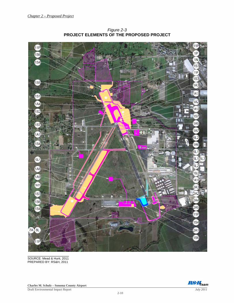
2.2.4 Meeting the Objectives Related to Air Transportation Services The project elements identified in the Master Plan would result in physical changes at the Airport that would support the continuation of the Airport’s ability to meet the air transportation service demands of local residents and businesses. These project elements have been developed to enable the County to plan for and accommodate the increased demand forecast for such services at the Airport. 2.3 PROPOSED PROJECT The Proposed Project would incorporate 40 project elements that are categorized based on the nature of each project element into the following categories: airfield, supporting project (those project elements that are necessary to support the airfield project elements), navigation aids, and property acquisition. Table 2-3 identifies those project elements that would be implemented by 2015 (short-term project elements). The short-term project elements are being reviewed at a project level of analysis. Table 2-4 identifies those project elements that are planned to be implemented between 2015 and 2030 (long-term project elements). The long-term project elements are being reviewed at a programmatic level of analysis. The project elements were given IDs (e.g., 1A1, 1S3, 2A2, etc.) in Tables 2-3 and 2-4 to make it easier to identify the location of the project element on Figure 2-3. The elements of the Proposed Project are those actions needed to implement FAA-required airfield safety improvements and other actions that will implement the Airport Master Plan. These two sets of actions are broadly described in the paragraphs that follow. Each element is subsequently described and illustrated. In addition to the project elements, full implementation of the Proposed Project requires amendments to the Sonoma County General Plan and a compatibility review by the Sonoma County Airport Land Use Commission (ALUC). A number of project elements are necessary to meet RSA requirements and to achieve the decoupling of the ends of Runways 14 and 19 where these two runway ends converge. The decoupling would result in eliminating the confusion that could occur because taxiways normally connect to runways at a right angle (i.e., 90 degrees). Currently, the taxiway connecting to the primary runway (Runway 14/32) requires a 150 degrees turn and a standard 90 degrees turn places aircraft on the crosswind runway (Runway 1/19). Given that the length and width of each of the runways are different, it is important for pilots to use the correct runway when departing from the Airport. The design of the Proposed Project accomplishes the decoupling while minimizing new pavement and complying with FAA design standards. These connected actions are included to enable the Airport to operate during construction activities. The essential elements are:
• installation of runway edge lights on Runway 1/19; • construction of a partial parallel taxiway (Taxiway V) to serve Runway 1/19; and • strengthening and widening Taxiway B to accommodate airline aircraft.
These three project elements would permit Runway 1/19 to be used when construction activities require closure of Runway 14/32.

Chapter 2 – Proposed Project
Charles M. Schulz – Sonoma County Airport Draft Environmental Impact Report July 2011 2-8
Table 2-3
SUMMARY OF SHORT-TERM PROJECT ELEMENTS OF THE PROPOSED PROJECT
ID/a/ /b/ Project Element
1A1 Extend Runway 14/32 by 885 feet for a total pavement length of 6,000 feet 1A2 Extend Runway 1/19 by 200 feet for a total pavement length of 5,202 feet 1A3 Extend Taxiway Y / construct bypass taxiway to Runway 14/32 1A4 Construct 200-foot blast pad for Runway 14 approach end 1A5 Construct replacement run-up apron located between Taxiway Y and A 1A6 Remove existing run-up and taxiways at approach end of Runway 14 1A7 Construct new taxiway between Runway 14/32 and Taxiway Y 1A8 Widen RSA to 500 feet and add runway edge lights to Runway 1/19 1A9 Construct Taxiway V with edge lights and standard signage 1A10 Reconstruct and widen Taxiway B between Runway 14/32 and Runway 1/19 1A11 Remove segment of Taxiway D and re-grade site 1A12 Construct connecting taxiway to Runway 1/19 and Taxiway Y 1A13 Construct 200-foot -blast pad for Runway 19 approach end 1S1 Realign Airport Creek and put portion of creek into a culvert 1S2 Place high-water ditch into a culvert 1S3 Construct RSA beyond approach ends of Runways 1, 14, and 19 1S4 Relocate and pave access roads outside RSA for all runways 1S5 Remove trees and vegetation for airspace clearance 1S6 Temporarily cover or disturb land used for haul roads, staging and spoils areas 1S7 Create three stormwater basins 1N Relocate localizer antenna, equipment building, and construct standby generator 1P Acquire three parcels of land for RSA construction and approach protection
2A1 Extend Taxiway D to approach end of Runway 32
2A2 Remove eastern segment of Taxiway D
/a/ The location of each project element is shown on Figure 2-3. /b/ “A” represents an Airfield project, “S” represents a Supporting project, “N” represents a Navigation Aid
project, and “P” represents Property Acquisition project. SOURCE: Mead & Hunt, 2011 PREPARED BY: RS&H, 2011

Chapter 2 – Proposed Project
Charles M. Schulz – Sonoma County Airport Draft Environmental Impact Report July 2011 2-9
Table 2-4
SUMMARY OF LONG-TERM PROJECT ELEMENTS OF THE PROPOSED PROJECT
ID/a/ /b/ Project Element
2A3 Remove Taxiway Z and regrade site
2A4 Construct replacement run-up apron for approach end to Runway 32
2A5 Remove existing run-up apron for approached end to Runway 32 and regrade site
3A Maintain existing airfield pavement through the use of slurry seals, overlays or repairs of isolated failures
4S Trim or remove individual trees in the vicinity of the airport that grow into the airspace required to be protected
5L1 Construct a replacement airline passenger terminal
5L2 Re-use or demolish the existing airline passenger terminal building
5L3 Demolish helipads that are currently not operational
6L1 Demolish the existing ARFF (Aircraft Rescue and Fire Fighting) building
6L2 Construct a replacement ARFF building
7A Construct new taxilanes to provide access to new private-use hangars
8L Designate a site for an air cargo facility to serve small-package shipping
9A Identify an on-airport aiming point for helicopter landings
10L1 Develop a new Air Traffic Control Tower (ATCT)
10L2 Reuse or demolish existing ATCT
11P
Acquire property designated in the Master Plan Update (and not associated with the Runway 14-32 extension) for approach protection, including: relocation of residents; demolition of buildings; filling man-made ponds on these properties; and installing new perimeter fencing.
12S
Relocate and/or construct miscellaneous aviation support facilities. Examples include replacing landing aids (replace the VASI with a PAPI) or construction of individual hangars as in-fill projects.
/a/ The location of each project element is shown on Figure 2-3. /b/ “A” represents an Airfield project, “S” represents a Supporting project, “N” represents a Navigation Aid
project, and “P” represents Property Acquisition project. SOURCE: Mead & Hunt, 2011 PREPARED BY: RS&H, 2011
Chapter 2 – Proposed Project
Charles M. Schulz – Sonoma County Airport Draft Environmental Impact Report July 2011 2-10
Figure 2-3 PROJECT ELEMENTS OF THE PROPOSED PROJECT
SOURCE: Mead & Hunt, 2011 PREPARED BY: RS&H, 2011

Chapter 2 – Proposed Project
Charles M. Schulz – Sonoma County Airport Draft Environmental Impact Report July 2011 2-11
With the implementation of the short-term project elements, the RSAs at the approach ends of Runways 19 and 32 would not have full-length graded RSAs. Instead, based on FAA direction, the Declared Distance concept would be used as a means of meeting RSA standards. The RSA standards for these runway ends specify that there be 600 feet of RSA before the landing threshold and 1,000 feet beyond the departure end of the runway. The approach ends for Runway 19 and 32 would meet the standard for landings. However, departures on Runway 1 (towards the approach end of Runway 19) would have a graded RSA that is 400 feet less than the RSA standard. Similarly, departures on Runway 14 (towards the approach end of Runway 32) would have a graded RSA that is 100 feet less than the RSA standard. Figure 2-4 depicts the dimensions of these RSAs in terms of the declared distances. Per FAA regulations, this information is made available to pilots through publication in the FAA’s Airport/Facility Directory, which is the official source for information on an airport’s facilities. A declared distance table would be included with the information for the Airport and would inform pilots that the runway length available for departures on Runway 1 and 14 are less than the actual length of the runway. The Airfield/Facility Directory would indicate (after the two runways are extended) that Runway 14 has 5,900 feet available for departures and Runway 1 has 4,802 feet available for departures.
Figure 2-4 DECLARED DISTANCE FOR RUNWAYS 1 AND 14
SOURCE: Mead & Hunt, 2011 PREPARED BY: RS&H, 2011 Implementation of the Proposed Project includes maintenance activities on and near the Airport, construction of new or replacement aviation facilities, and acquisition of property. All of the safety improvements are being reviewed at a project level and are included as part of the short-
Chapter 2 – Proposed Project
Charles M. Schulz – Sonoma County Airport Draft Environmental Impact Report July 2011 2-12
term project elements. All of the long-term project elements are being reviewed at a programmatic level, which means that these actions will require subsequent CEQA review before implementation could occur. 2.3.1 Short-Term Project Elements The principal short-term project elements are a northwesterly extension (885 feet) of Runway 14/32 to 6,000 feet, a northeasterly extension (200 feet) of Runway 1/19 to 5,202 feet, construction of connecting taxiways, realigning about 1,500 feet of Airport Creek that includes about 700 feet into a new channel and about 650 feet into a culvert, and related drainage improvements. A detailed listing of the short-term project elements includes the following: 2.3.1.1 Airfield Projects The airfield project elements of the Proposed Project include those elements directly involved with aircraft ground operations. A list of these 15 airfield elements is identified and described below. Runway 14/32 Extension The approach end of Runway 14 would be extended by 885 feet to the north for a total runway length of 6,000 feet. This element would include an extension of runway edge lights, signs, and markings for the additional 885-feet of new runway (see 1A1 in Figure 2-3 for a project element location).
Runway 1/19 Extension The approach end of Runway 19 would be extended by 200 feet to the north for a total runway length of 5,202 feet. This element would include the relocation and addition of runway lights, signs, and markings (see 1A2 in Figure 2-3 for a project element location). Taxiway Y Extension and Bypass Taxiway Construction Taxiway Y would be extended to connect to the new Runway 14 approach end. This element would also include constructing a bypass taxiway to connect to the new Runway 14 approach end. In addition, this component would include the extension of taxiway edge lights, signage, and markings (see 1A3 in Figure 2-3 for a project element location).
Blast Pad Construction North of Runway 14 Approach End A 200-foot-long blast pad would be constructed north of the new Runway 14 approach end. This element, which is required for all runway ends and does not add any usable runway length, would also include marking the new pavement (see 1A4 in Figure 2-3 for a project element location).
Run-Up Apron Construction An aircraft run-up apron located in the northeast corner of the intersection of Taxiway Y and Taxiway A would be constructed (see 1A5 on Figure 2-3 for a project element location). Prior to this construction, the existing run-up apron would need to be removed. Run-Up Apron and Taxiway Removal The existing aircraft run-up apron and taxiways in that portion of Taxiway A between Runway 14/32 and Taxiway Y, and that portion of Taxiway Y between its intersection with Taxiway A and Runway 14/32 would be removed (see 1A6 in Figure 2-3 for a project element location).

Chapter 2 – Proposed Project
Charles M. Schulz – Sonoma County Airport Draft Environmental Impact Report July 2011 2-13
Taxiway Construction A new taxiway between Runway 14/32 and Taxiway Y to replace the portion of Taxiway A which was previously removed (see 3.2.1.5 for a project element description), would be constructed (see 1A7 in Figure 2-3 for a project element location). Runway 1/19 RSA Widening and Edge Lights Installation The RSA for Runway 1/19 would be widened from 400 feet to 500 and edge lights would be installed. This element would include the installation of electrical lines running from Runway 14/32 along Taxiway B to Runway 1/19 (see 1A8 in Figure 2-3 for a project element location). Partial Parallel Taxiway V Construction A new partial parallel taxiway (Taxiway V) would be constructed along the eastern side of Runway 1/19. This element would include the installation of taxiway edge lights, signage and markings (see 1A9 in Figure 2-3 for a project element location). Taxiway B Reconstruction Taxiway B would be reconstructed and widened between Runway 14/32 and Runway 1/19 to accommodate aircraft in Category C-III. This element would include the installation of taxiway edge lights, signage, and markings (see 1A10 in Figure 2-3 for a project element location). Partial Taxiway D Removal The segment of Taxiway D that connects to the approach end of Runway 1 would be removed. This element would also include regrading the existing site (see 1A11 in Figure 2-3 for a project element location). Taxiway Construction A connecting taxiway located at the new approach end of Runway 19 and Taxiway Y would be constructed. This element would include the installation of taxiway lights, signage, and markings (see 1A12 in Figure 2-3 for a project element location). Blast Pad Construction North of Runway 19 Approach End A 200-foot long blast pad located north of the beyond the approach end of Runway 19 would be constructed. This project element, which is required for all runway ends and does not add any usable runway length, also would include marking the new pavement (see 1A13 in Figure 2-3 for a project element location) Taxiway D Extension Taxiway D would be extended to its intersection with the approach end of Runway 32. This element would include the installation of taxiway edge lights, signage, and markings (see 2A1 in Figure 2-3 for a project element location). Partial Taxiway D Removal The eastern segment of Taxiway D located near the approach end of Runway 32 would be removed (see 2A2 in Figure 2-3 for a project element location).

Chapter 2 – Proposed Project
Charles M. Schulz – Sonoma County Airport Draft Environmental Impact Report July 2011 2-14
2.3.1.2 Supporting Projects Supporting project elements include those project elements that are necessary to support the airfield project elements. These seven supporting project elements are identified and described below. Realign Airport Creek This project element would realign Airport Creek to accommodate the RSAs for Runways 14 and 19. The realignment will include a realignment of the creek to place the creek outside of the RSAs and will include a culvert of up to 650 feet beneath the RSA (see 1S1 in Figure 2-3 for project element location). High-Water Ditch Culvert Placement A high-water ditch that hydrologically connects Airport Creek to a segment of Ordinance Creek would be placed into a culvert (see 1S2 in Figure 2-3 for a project element location). RSA Construction An FAA standard (1,000-foot-long by 500-foot-wide) graded RSA beyond the approach ends of Runways 14, 19, and 32 would be constructed (see 1S3 in Figure 2-3 for a project element location). Access Road Relocation All access roads located around the approach ends of each runway would be relocated outside the RSA. This element would include site preparation and paving of the new access road alignments (see 1S4 in Figure 2-3 for a project element location). Tree and Shrub Removal Trees and shrubs would be removed to provide required airspace clearance for the approach ends of Runways 14 and 19 (see 1S5 in Figure 2-3 for a project element location).
Land Preparation Land used for haul roads, staging and spoils areas created in support of construction of runway safety enhancements would be covered or disturbed (see 1S6 in Figure 2-3 for a project element location). Stormwater Basin Construction Three stormwater basins (one north of Taxiway A, one west of the approach end of Runway 14, and one in the southeastern portion of the Airport) would be constructed (see 1S7 in Figure 2-3 for a project element locations). The stormwater basin in the southeastern portion of the Airport would require breaching and filling in the existing pond and creating a new stormwater basin on Airport property. 2.3.1.3 Navigational Aid Project The localizer antenna and equipment building for Runway 14/32 would be relocated and a standby generator would be installed. The standby generator would be used to provide emergency power to the new localizer (see 1N in Figure 2-3 for a project element location).

Chapter 2 – Proposed Project
Charles M. Schulz – Sonoma County Airport Draft Environmental Impact Report July 2011 2-15
2.3.1.4 Property Acquisition Project Three parcels of land totaling approximately 22.7 acres would be acquired for the construction of a new access road around the approach end of Runway 14, for runway protection zones, and for the relocation of Airport Creek (see 1P in Figure 2-3 for a project element location). 2.3.2 Long-Term Project Elements The Proposed Project consists of a series of related actions – individual project elements that will be implemented, if at all, over time depending on need and available funding. The EIR presents an assessment of the Proposed Project’s impacts as a whole based upon the general descriptions set forth in the Master Plan. For the purposes of this assessment, the EIR assumes that all long-term project elements will be implemented. The EIR focuses on those impacts of the overall project that may be significant and highlights potential impacts that will need to be further evaluated as precise scopes, designs, and locations of long-term project components are being more clearly defined. Project-level impacts of individual long-term project elements of the Proposed Project are not included in the EIR. More focused project-level environmental analysis of each long-term project element will be undertaken by the County prior to any element being considered for approval and implementation. The principal long-term project elements include construction of a replacement airline passenger terminal, relocation of the aircraft rescue and firefighting (ARFF) building, and relocation of the air traffic control tower to the west side of the airport. Ongoing activities over the 20-year planning period includes pavement maintenance, construction of new or replacement aircraft storage hangars, and acquisition of property to protect the approaches to the runways. A detailed listing of the long-term project elements includes the following: 2.3.2.1 Airfield Projects The long-term airfield project elements of the Proposed Project include those elements directly involved with aircraft ground operations. A list of these four airfield elements is identified and described below. Taxiway Z Removal Taxiway Z would be removed and the site would be regraded. Currently, Taxiway Z connects Runway 14-32 to its parallel taxiway, Taxiway Y (see 2A3 in Figure 2-3 for a project element location). Construction of Run-up Apron for Runway 32 A run-up apron would be constructed adjacent to the approach end of Runway 32 to replace the run-up apron being removed (see 2A4 in Figure 2-3 for a project element location). Removal of Run-up Apron for Runway 32 The existing run-up apron lies within the Precision Obstacle Free Zone for the approach end of Runway 32. Following (or as part of) construction of a replacement run-up apron, the existing apron would be removed and the site regraded (see 2A5 in Figure 2-3 for a project element location).

Chapter 2 – Proposed Project
Charles M. Schulz – Sonoma County Airport Draft Environmental Impact Report July 2011 2-16
Airfield Pavement Maintenance During the 20-year planning period, existing and subsequently constructed airfield pavement will be maintained. Maintenance actions may include the use of slurry seals, overlays or repairs of isolated failures (this project element, which is identified as 3A and includes all airfield pavement, is not shown in Figure 2-3). Construct Taxilanes to New Hangars New taxilanes would be constructed, as needed, to provide aircraft access to new private aircraft hangars on the south side of the Airport (see 7A in Figure 2-3 for a project element location). Identify On-airport Aiming Point for Helicopters An aiming point for transient (i.e., visiting) helicopters would be designated. This would permit Air Traffic Control staff to direct incoming helicopters to a specific site. Helicopters would hover at this point before taxiing to a parking position. A specific site for this aiming point has not been designated. Airport staff would coordinate with Air Traffic Control staff to define an optimum site. It will be located on the east side of Airport on existing pavement. 2.3.2.2 Supporting Projects Supporting project elements include those project elements that are necessary to support the airfield project elements. These two long-term supporting project elements are identified and described below. Trim or Remove Trees FAA-defined airspace around the airport needs to be protected from obstructions. On- or off-Airport trees that are not now obstructions may grow into the protected airspace. These trees would be topped or removed to eliminate the potential hazard (this project element, which is identified as 4S, would occur wherever necessary on Airport and is not shown in Figure 2-3). Relocate and/or Construct Miscellaneous Aviation Support Facilities Miscellaneous aviation supporting facilities would be relocated or constructed. One example would be replacement of an existing landing aid with a newer version (e.g., replacement of VASI with a PAPI). Another example would be construction of individual hangars as an in-fill project (this project element, which is identified as 12S, would occur at various locations on the Airport and is not shown in Figure 2-3). 2.3.2.3 Landside Projects The long-term landside project elements include those elements associated with landside operations at the Airport. A list of these seven landside elements is identified and described below. Construct Replacement Airline Passenger Terminal A replacement airline passenger terminal would be constructed to accommodate forecast growth in the number of passengers. The terminal would be located immediately north of the existing terminal building. The adjacent parking lots and roads would be reconfigured to serve the new terminal location (see 5L1 in Figure 2-3 for a project element location).

Chapter 2 – Proposed Project
Charles M. Schulz – Sonoma County Airport Draft Environmental Impact Report July 2011 2-17
Reuse or Demolish Existing Passenger Terminal When the replacement passenger terminal is constructed, the existing terminal will not be needed for its present purpose. Until a design for the new terminal is approved, it will not be known whether the existing terminal will be reused (in whole or part) or demolished (see 5L2 in Figure 2-3 for a project element location). Demolish Helipad This action would remove the painted helipad markings and demolish four helicopter parking positions. This facility has been out of service for many years. The area will ultimately be reused as part of the replacement passenger terminal and its associated aircraft parking apron (see 5L3 in Figure 2-3 for a project element location). Demolish Existing ARFF Building The Aircraft Rescue and Fire Fighting (ARFF) building is currently located immediately north of the airline passenger terminal. The proposed site for a replacement passenger terminal includes the current ARFF building. Therefore, the project would move the ARFF building to a site that would not conflict with the future passenger terminal (see 6L1 in Figure 2-3 for a project element location). Construct a Replacement ARFF Building A replacement ARFF building would be constructed on a site between Taxiways A and H (see 6L2 in Figure 2-3 for a project element location). Develop a Replacement Air Traffic Control Tower The existing Air Traffic Control Tower is not optimally located to observe both aircraft in the air and aircraft taxiing on the ground. The Airport Master Plan identified two possible new sites (see 10L1 in Figure 2-3 for a project element location). However, the FAA would conduct an independent study to identify a site. Until that study is undertaken the actual future site will not be known. Reuse or Demolish Existing Air Traffic Control Tower Once a replacement Air Traffic Control Tower is constructed, the existing tower would be either reused or demolished (see 10L2 in Figure 2-3 for a project element location). 2.3.2.4 Property Acquisition Projects A variety of properties north, northwest, south and southwest of the Airport would be acquired for approach protection. These properties are in addition to those directly needed to construct the runway extensions. This property acquisition of 84 acres could include relocation of residents, demolition of buildings, filling of man-made ponds, and installing new perimeter fencing (see 11P in Figure 2-3 for a project element location). 2.3.3 Construction Process Construction activities for the near-term project elements will consist of three major components: earthwork (cutting and filling), paving and construction of drainage facilities. The primary contractor staging area will be immediately south of Sanders Road. A secondary contractor staging area will be located at the south end of the airport west of the end of Runway 32. Construction crews and trucks will access the site principally through the northern contractor

Chapter 2 – Proposed Project
Charles M. Schulz – Sonoma County Airport Draft Environmental Impact Report July 2011 2-18
staging area. These vehicles are expected to reach the site via Shiloh Road, Windsor Road to Sanders Road. Most (and potentially all) fill materials will be obtained from on-airport borrow sites. The primary borrow site will be located on the west side of the Airport immediately west of the end of Runway 1. Soil will be transported using scrapers or dump trucks to fill sites via on-airport service roads. Most fill will be deposited in the area north of the existing runways in the vicinity of Airport Creek. Gravel and asphalt will likely be delivered to the site in trucks. Access is expected to be via the northern contractor staging area. Due to the need to minimize disruption of scheduled airline service, some construction and paving will occur at night. One stormwater retention basin will be constructed in the area north of Runway 1-19. One detention basin will be constructed east of the end of Runway 19. A second detention basin will be constructed east of the end of Runway 32. Various drop inlets, pipes and ditches will convey stormwaters to the collection basins. Box culverts will be constructed immediately north of the present location of Aviation Creek. This creek will be rerouted to flow through the culverts. 2.3.3 Project Element Phasing 2.3.3.1 Phase I of Short-Term Project Elements Project elements in Phase I of the Proposed Project are identified in Table 2-5. The primary project elements are the proposed extension of Runway 1/19 by 200 feet to the north (which is the first element in accomplishing the de-coupling of the approach ends of Runways 14 and 19) and the construction of the RSAs for the approach ends of Runways 14, 19, and 32. Table 2-5 identifies the activities needed to complete Phase I of the Proposed Project. 2.3.3.2 Phase II of Short-Term Project Elements Project elements in Phase II of the Proposed Project are identified in Table 2-6. The primary project element is the proposed extension of Runway 14/32 by 885 feet. Table 2-6 identifies other airfield and support project elements that are functionally related to the proposed extension of Runway 14/32. The sequence, description, and duration of these project elements is identified. 2.3.3.3 Long-Term Project Elements The long-term project elements include those that will be ongoing, those that are expected to occur during a particular timeframe, and those that may occur during the 20-year life of the Master Plan. Table 2-7 presents the expected schedule for the programmatic project elements.

Chapter 2 – Proposed Project
Charles M. Schulz – Sonoma County Airport Draft Environmental Impact Report July 2011 2-19
Table 2-5 PHASE I PROJECT ELEMENTS
Order /a/ Project Element Description Duration
(Days) 1 Mobilize equipment and prepare construction sites [project element 1S6] 20
2 Close Runway 1/19 [project element 1A7] 100
3 Remove Taxiway D [project element 1A11] 10
4 Install Runway 1/19 edge lights and signs [project element 1A9] 30
5 Construct Taxiway V and install edge lights and signs [project element 1A9] 40
6 Construct Taxiway Y and bypass taxiway earthwork [project elements 1A2, 1A5, 1S3, and 1S4]
45
7 Construct Taxiway Y run-up apron earthwork [project element 1A4] 40
8 Overlay and widen Taxiway B [project element 1A10] 20
9 Extend Runway 1-19 [project elements 1A7, 1A12, and 1A13] 20
10 Install drainage improvements and culverts to Airport Creek [project elements 1S1, 1S2, and 1S7]
60
11 Prepare Runway 19-14 RSA and fill Taxiway Y (fill platform) [project elements 1S3 and 1A2]
40
12 Relocate navigation equipment (localizer/equipment building) [project element 1N] 100
13 Construct new taxiway between Runway 14-32 and Taxiway Y [project element 1A6]
25
14 Install pavement markings [project elements 1A2, 1A7, and 1A9] 5
15 Install erosion control [project elements 1A2, 1A7, and 1A9] 5
16 Winterize site [project elements 1A2, 1A7, and 1A9] 10
/a/ The schedule of some elements overlap. SOURCE: Mead & Hunt, 2011 PREPARED BY: RS&H, 2011

Chapter 2 – Proposed Project
Charles M. Schulz – Sonoma County Airport Draft Environmental Impact Report July 2011 2-20
Table 2-6 PHASE II PROJECT ELEMENTS
Order /a/ Project Element Description Duration
(Days) 1 Mobilize equipment and prepare construction site [project element 1S6] 20
2 Relocate navigation equipment (localizer/equipment building) [project element 1N] 100
3 Extend Runway 14-32 and Taxiway Y [project elements 1A1, 1A2, and 1A3] 45
4 Construct Taxiway Y apron [project element 1A4] 40
5 Relocate Taxiway D [project element 2A1 and 2A2] 45
6 Remove old Taxiway A and Taxiway Y [project element 1A5] 15
7 Drain and fill South Pond [project element 1S4] 15
8 Relocate Runway 32 perimeter road [project element 1S4] 30
9 Relocate Runway 14 perimeter road [project element 1S4] 15
10 Install pavement markings [project elements 1A1, 1A2, and 1A4] 5
11 Install erosion control [project elements 1A1, 1A2, 1A4, 1A5, 1S4, 1N, 2A1, and 2A2]
5
/a/ The relocation of the navigation equipment is dependent on an FAA reimbursable agreement and the project schedule will
be determined by the FAA. SOURCE: Mead & Hunt, 2011 PREPARED BY: RS&H, 2011

Chapter 2 – Proposed Project
Charles M. Schulz – Sonoma County Airport Draft Environmental Impact Report July 2011 2-21
Table 2-7
SCHEDULE FOR PROGRAMMATIC ELEMENTS ID Project Schedule 2A3 Taxiway Z removal 5-10 Years
2A4 Construct replacement run-up apron for approach end to Runway 32 5-10 Years
2A5 Remove existing run-up apron for approached end to Runway 32 and regrade site 5-10 Years
3A Airfield pavement maintenance Ongoing
4S Isolated tree trimming or removal Ongoing
5L1 Construct replacement airline passenger terminal 5-10 Years
5L2 Reuse or demolish existing passenger terminal 5-10 Years
5L3 Demolish helipad 5-10 Years
6L1 Demolish existing ARFF Building 3-5 Years
6L2 Construct replacement ARFF Building 3-5 Years
7A Construct taxilanes to new hangars 5+ Years
N/A Identify on-airport aiming point for helicopters Indefinite
10L1 Develop a replacement Air Traffic Control Tower 10+ Years
10L2 Reuse or demolish existing Air Traffic Control Tower 10+ Years
11P Acquire property for approach protection Ongoing
12S Relocate and/or construct miscellaneous aviation support facilities Ongoing
SOURCE: Mead & Hunt, 2011 PREPARED BY: RS&H, 2011 2.4 PERMITS AND APPROVALS Permits and approvals that would be required for the implementation of the Proposed Project include the following:
• General Construction Stormwater Permit from the Regional Water Quality Control Board • General Industrial Stormwater Permit from the Regional Water Quality Control Board • Section 404 Permit from the U.S. Army Corps of Engineers • Section 401 Permit from the Regional Water Quality Control Board • 1602 Permit from the California Department of Fish and Game • Amended Airport Permit from the State of California Division of Aeronautics • Approval of Airport Master Plan from County of Sonoma Board of Supervisors • Approval of Amendments to the Air Transportation Element from County of Sonoma
Board of Supervisors

Chapter 2 – Proposed Project
Charles M. Schulz – Sonoma County Airport Draft Environmental Impact Report July 2011 2-22
THIS PAGE INTENTIONALLY LEFT BLANK