e3f2 photoelectric sensors data sheet - universidad de … · photoelectric sensorse3f2 1...
TRANSCRIPT
Photoelectric Sensors E3F2 1
Photoelectric Sensors
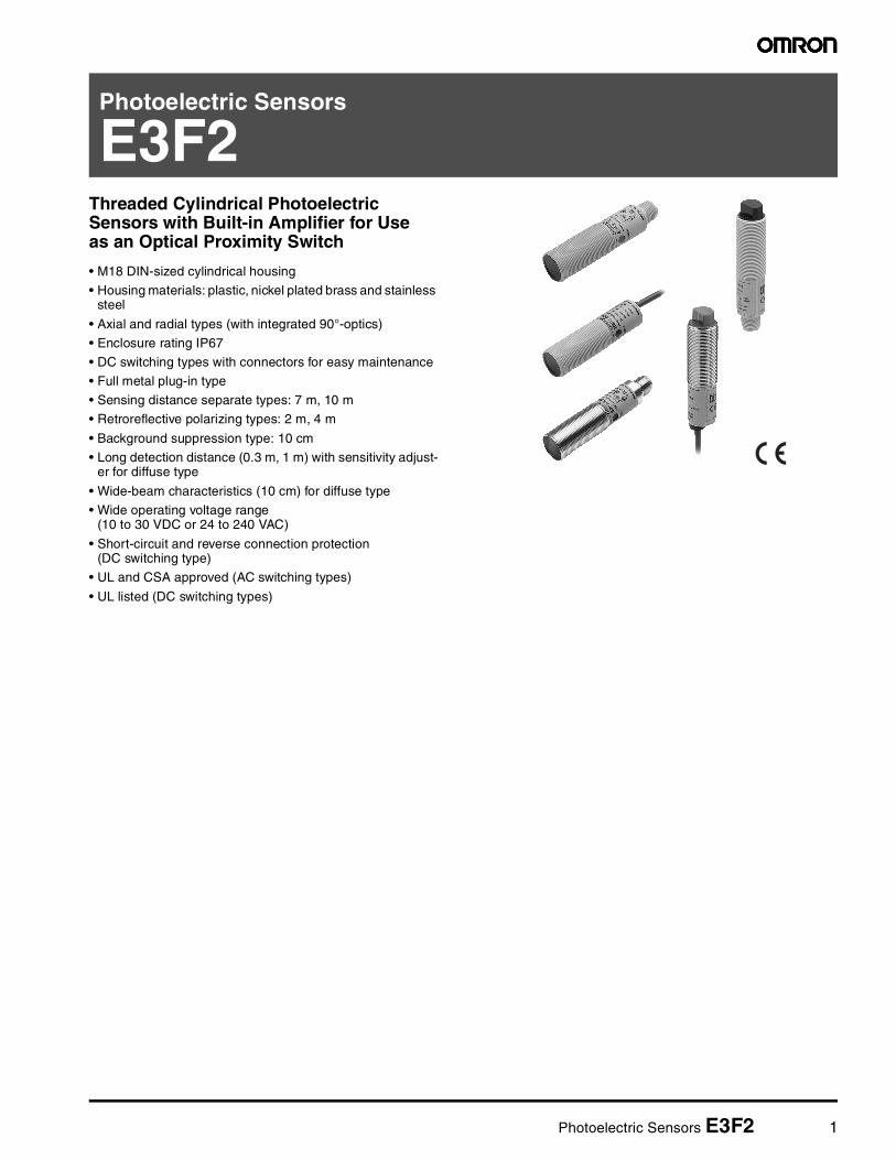
E3F2Threaded Cylindrical Photoelectric Sensors with Built-in Amplifier for Use as an Optical Proximity Switch
• M18 DIN-sized cylindrical housing
• Housing materials: plastic, nickel plated brass and stainless steel
• Axial and radial types (with integrated 90°-optics)
• Enclosure rating IP67
• DC switching types with connectors for easy maintenance
• Full metal plug-in type
• Sensing distance separate types: 7 m, 10 m
• Retroreflective polarizing types: 2 m, 4 m
• Background suppression type: 10 cm
• Long detection distance (0.3 m, 1 m) with sensitivity adjust-er for diffuse type
• Wide-beam characteristics (10 cm) for diffuse type
• Wide operating voltage range (10 to 30 VDC or 24 to 240 VAC)
• Short-circuit and reverse connection protection (DC switching type)
• UL and CSA approved (AC switching types)
• UL listed (DC switching types)
2 Photoelectric Sensors E3F2
Ordering Information
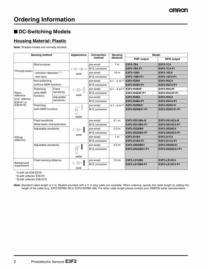
DC-Switching Models
Housing Material: PlasticNote: Shaded models are normally stocked.
Note: Standard cable length is 2 m. Models provided with a 5 m long cable are available. When ordering, specify the cable length by adding thelength of the cable (e.g. E3F2-R2RB4 2M or E3F2-R2RB4 5M). For other cable length please contact your OMRON sales representative.
Sensing method Appearance Connectionmethod
Sensingdistance
Model
PNP output NPN output
Through-beam
Multi purpose
axial
pre-wired 7 m E3F2-7B4 E3F2-7C4
M12 connector E3F2-7B4-P1 E3F2-7C4-P1
- precision detection (*1)
- test input
pre-wired 10 m E3F2-10B4 E3F2-10C4
M12 connector E3F2-10B4-P1 E3F2-10C4-P1
Retro-reflective(incl. reflector E39-R1 or E39-R1S)
Non-polarizing(without MSR function)
axial
pre-wired 0.1 - 2 m(*2) E3F2-R2B4 E3F2-R2C4
M12 connector E3F2-R2B4-P1 E3F2-R2C4-P1
Polarizing(with MSR function)
Fixed sensitivity
pre-wired 0.1 - 4 m(*3) E3F2-R4B4F E3F2-R4C4F
M12 connector E3F2-R4B4F-P1 E3F2-R4C4F-P1
Adjustablesensitivity
pre-wired E3F2-R4B4 E3F2-R4C4
M12 connector E3F2-R4B4-P1 E3F2-R4C4-P1
Polarizing(with MSR function)
radial
pre-wired 0.1 - 2 m(*2) E3F2-R2RB41 E3F2-R2RC41
M12 connector E3F2-R2RB41-P1 E3F2-R2RC41-P1
Diffuse reflective
Fixed sensitivityWide-beam characteristics
axial
pre-wired 0.1 m E3F2-DS10B4-N E3F2-DS10C4-N
M12 connector E3F2-DS10B4-P1 E3F2-DS10C4-P1
Adjustable sensitivity pre-wired 0.3 m E3F2-DS30B4 E3F2-DS30C4
M12 connector E3F2-DS30B4-P1 E3F2-DS30C4-P1
pre-wired 1 m E3F2-D1B4 E3F2-D1C4
M12 connector E3F2-D1B4-P1 E3F2-D1C4-P1
Adjustable sensitivity
radial
pre-wired 0.3 m E3F2-DS30B41 E3F2-DS30C41
M12 connector E3F2-DS30B41-P1 E3F2-DS30C41-P1
Background suppression
Fixed sensing distance
axial
pre-wired 10 cm E3F2-LS10B4 E3F2-LS10C4
M12 connector E3F2-LS10B4-P1 E3F2-LS10C4-P1
*1) with slit E39-ES18*2) with reflector E39-R1*3) with reflector E39-R1S
Photoelectric Sensors E3F2 3
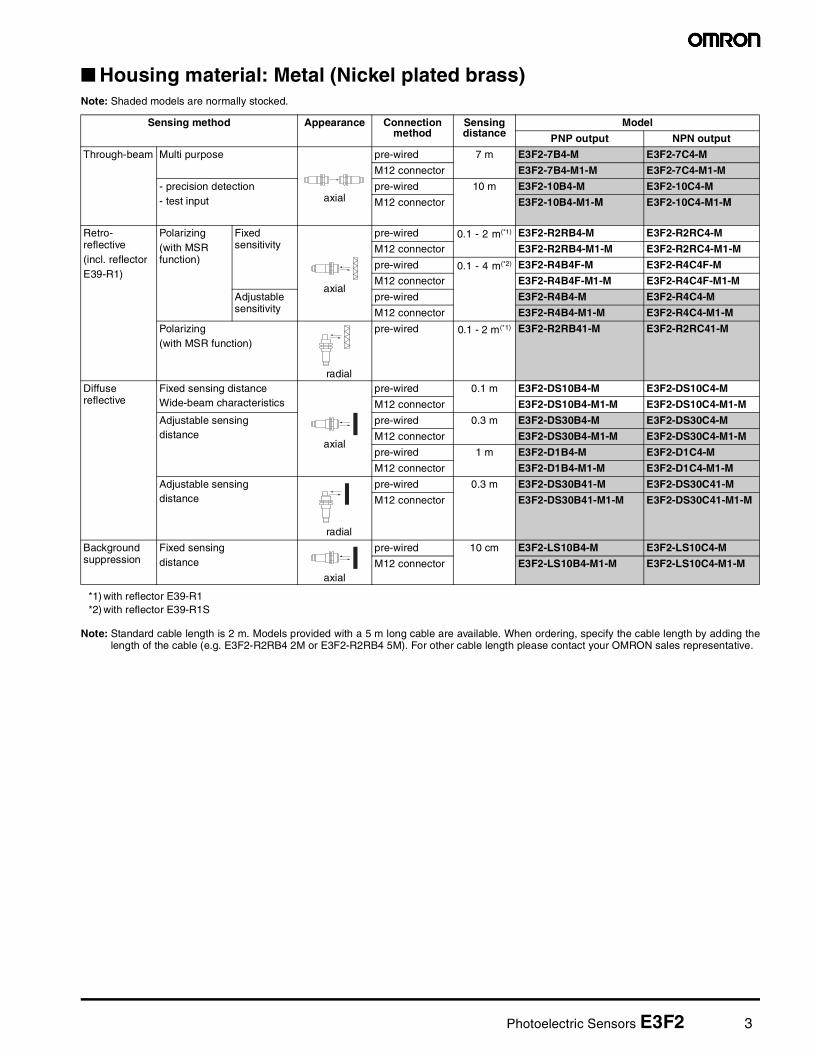
Housing material: Metal (Nickel plated brass)Note: Shaded models are normally stocked.
Note: Standard cable length is 2 m. Models provided with a 5 m long cable are available. When ordering, specify the cable length by adding thelength of the cable (e.g. E3F2-R2RB4 2M or E3F2-R2RB4 5M). For other cable length please contact your OMRON sales representative.
Sensing method Appearance Connection method
Sensing distance
Model
PNP output NPN output
Through-beam Multi purpose
axial
pre-wired 7 m E3F2-7B4-M E3F2-7C4-M
M12 connector E3F2-7B4-M1-M E3F2-7C4-M1-M
- precision detection- test input
pre-wired 10 m E3F2-10B4-M E3F2-10C4-M
M12 connector E3F2-10B4-M1-M E3F2-10C4-M1-M
Retro-reflective(incl. reflector E39-R1)
Polarizing(with MSR function)
Fixed sensitivity
axial
pre-wired 0.1 - 2 m(*1)
*1) with reflector E39-R1
E3F2-R2RB4-M E3F2-R2RC4-M
M12 connector E3F2-R2RB4-M1-M E3F2-R2RC4-M1-M
pre-wired 0.1 - 4 m(*2)
*2) with reflector E39-R1S
E3F2-R4B4F-M E3F2-R4C4F-M
M12 connector E3F2-R4B4F-M1-M E3F2-R4C4F-M1-M
Adjustablesensitivity
pre-wired E3F2-R4B4-M E3F2-R4C4-M
M12 connector E3F2-R4B4-M1-M E3F2-R4C4-M1-M
Polarizing(with MSR function)
radial
pre-wired 0.1 - 2 m(*1) E3F2-R2RB41-M E3F2-R2RC41-M
Diffuse reflective
Fixed sensing distanceWide-beam characteristics
axial
pre-wired 0.1 m E3F2-DS10B4-M E3F2-DS10C4-M
M12 connector E3F2-DS10B4-M1-M E3F2-DS10C4-M1-M
Adjustable sensing distance
pre-wired 0.3 m E3F2-DS30B4-M E3F2-DS30C4-M
M12 connector E3F2-DS30B4-M1-M E3F2-DS30C4-M1-M
pre-wired 1 m E3F2-D1B4-M E3F2-D1C4-M
M12 connector E3F2-D1B4-M1-M E3F2-D1C4-M1-M
Adjustable sensing distance
radial
pre-wired 0.3 m E3F2-DS30B41-M E3F2-DS30C41-M
M12 connector E3F2-DS30B41-M1-M E3F2-DS30C41-M1-M
Background suppression
Fixed sensing distance
axial
pre-wired 10 cm E3F2-LS10B4-M E3F2-LS10C4-M
M12 connector E3F2-LS10B4-M1-M E3F2-LS10C4-M1-M
4 Photoelectric Sensors E3F2
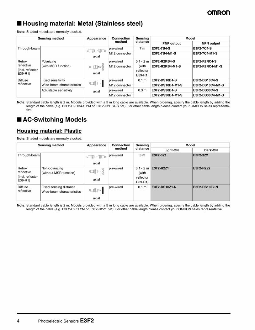
Housing material: Metal (Stainless steel)Note: Shaded models are normally stocked.
Note: Standard cable length is 2 m. Models provided with a 5 m long cable are available. When ordering, specify the cable length by adding thelength of the cable (e.g. E3F2-R2RB4-S 2M or E3F2-R2RB4-S 5M). For other cable length please contact your OMRON sales representa-tive.
AC-Switching Models
Housing material: PlasticNote: Shaded models are normally stocked.
Note: Standard cable length is 2 m. Models provided with a 5 m long cable are available. When ordering, specify the cable length by adding thelength of the cable (e.g. E3F2-R2Z1 2M or E3F2-R2Z1 5M). For other cable length please contact your OMRON sales representative.
Sensing method Appearance Connectionmethod
Sensingdistance
Model
PNP output NPN output
Through-beam
axial
pre-wired 7 m E3F2-7B4-S E3F2-7C4-S
M12 connector E3F2-7B4-M1-S E3F2-7C4-M1-S
Retro-reflective(incl. reflector E39-R1)
Polarizing(with MSR function)
axial
pre-wired 0.1 - 2 m(with
reflectorE39-R1)
E3F2-R2RB4-S E3F2-R2RC4-S
M12 connector E3F2-R2RB4-M1-S E3F2-R2RC4-M1-S
Diffuse reflective
Fixed sensitivityWide-beam characteristics
axial
pre-wired 0.1 m E3F2-DS10B4-S E3F2-DS10C4-S
M12 connector E3F2-DS10B4-M1-S E3F2-DS10C4-M1-S
Adjustable sensitivity pre-wired 0.3 m E3F2-DS30B4-S E3F2-DS30C4-S
M12 connector E3F2-DS30B4-M1-S E3F2-DS30C4-M1-S
Sensing method Appearance Connectionmethod
Sensingdistance
Model
Light-ON Dark-ON
Through-beam pre-wired 3 m E3F2-3Z1 E3F2-3Z2
axial
Retro-reflective(incl. reflector E39-R1)
Non-polarizing(without MSR function)
axial
pre-wired 0.1 - 2 m(with
reflectorE39-R1)
E3F2-R2Z1 E3F2-R2Z2
Diffuse reflective
Fixed sensing distanceWide-beam characteristics
axial
pre-wired 0.1 m E3F2-DS10Z1-N E3F2-DS10Z2-N
Photoelectric Sensors E3F2 5
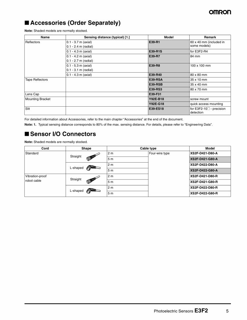
Accessories (Order Separately)Note: Shaded models are normally stocked.
For detailed information about Accessories, refer to the main chapter “Accessories” at the end of the document.
Note: 1. Typical sensing distance corresponds to 80% of the max. sensing distance. For details, please refer to “Engineering Data”.
Sensor I/O ConnectorsNote: Shaded models are normally stocked.
Name Sensing distance (typical) [1.] Model Remark
Reflectors 0.1 - 3.7 m (axial)0.1 - 2.4 m (radial)
E39-R1 60 x 40 mm (included in some models)
0.1 - 4.3 m (axial) E39-R1S for E3F2-R4
0.1 - 4.2 m (axial)0.1 - 2.7 m (radial)
E39-R7 84 mm
0.1 - 5.3 m (axial)0.1 - 3.1 m (radial)
E39-R8 100 x 100 mm
0.1 - 4.3 m (axial) E39-R40 80 x 80 mm
Tape Reflectors E39-RSA 35 x 10 mm
E39-RSB 35 x 40 mm
E39-RS3 80 x 70 mm
Lens Cap E39-F31
Mounting Bracket Y92E-B18 screw mount
Y92E-G18 quick access mounting
Slit E39-ES18 for E3F2-10@ - precision detection
Cord Shape Cable type Model
StandardStraight
2 m Four-wire type XS2F-D421-D80-A
5 m XS2F-D421-G80-A
L-shaped 2 m XS2F-D422-D80-A
5 m XS2F-D422-G80-A
Vibration-proofrobot cable Straight
2 m XS2F-D421-D80-R
5 m XS2F-D421-G80-R
L-shaped 2 m XS2F-D422-D80-R
5 m XS2F-D422-G80-R
6 Photoelectric Sensors E3F2
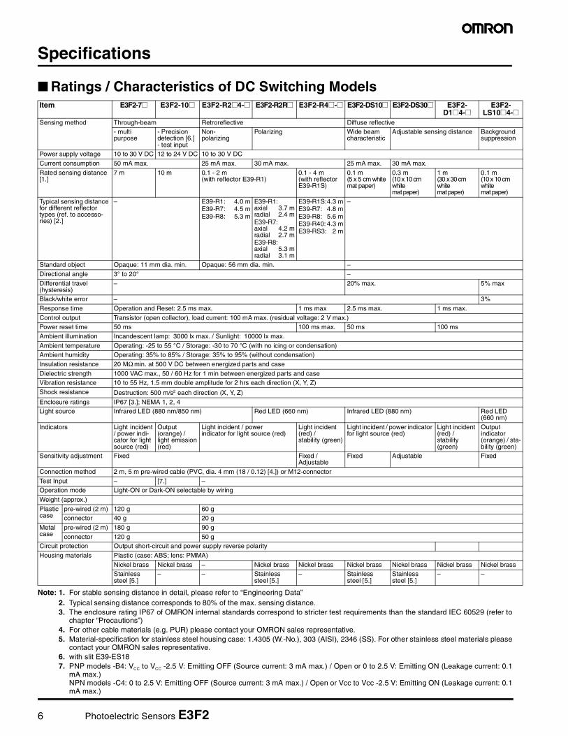
Specifications
Ratings / Characteristics of DC Switching Models
Note: 1. For stable sensing distance in detail, please refer to “Engineering Data”2. Typical sensing distance corresponds to 80% of the max. sensing distance.3. The enclosure rating IP67 of OMRON internal standards correspond to stricter test requirements than the standard IEC 60529 (refer to
chapter “Precautions”)4. For other cable materials (e.g. PUR) please contact your OMRON sales representative.5. Material-specification for stainless steel housing case: 1.4305 (W.-No.), 303 (AISI), 2346 (SS). For other stainless steel materials please
contact your OMRON sales representative.6. with slit E39-ES187. PNP models -B4: VCC to VCC -2.5 V: Emitting OFF (Source current: 3 mA max.) / Open or 0 to 2.5 V: Emitting ON (Leakage current: 0.1
mA max.)NPN models -C4: 0 to 2.5 V: Emitting OFF (Source current: 3 mA max.) / Open or Vcc to Vcc -2.5 V: Emitting ON (Leakage current: 0.1mA max.)
Item E3F2-7@ E3F2-10@ E3F2-R2@4-@ E3F2-R2R@ E3F2-R4@-@ E3F2-DS10@ E3F2-DS30@ E3F2-D1@4-@
E3F2-LS10@4-@
Sensing method Through-beam Retroreflective Diffuse reflective- multi purpose
- Precision detection [6.]- test input
Non-polarizing
Polarizing Wide beam characteristic
Adjustable sensing distance Background suppression
Power supply voltage 10 to 30 V DC 12 to 24 V DC 10 to 30 V DC
Current consumption 50 mA max. 25 mA max. 30 mA max. 25 mA max. 30 mA max.
Rated sensing distance [1.]
7 m 10 m 0.1 - 2 m(with reflector E39-R1)
0.1 - 4 m(with reflector E39-R1S)
0.1 m (5 x 5 cm white mat paper)
0.3 m(10 x 10 cm white mat paper)
1 m(30 x 30 cm white mat paper)
0.1 m(10 x 10 cm white mat paper)
Typical sensing distance for different reflector types (ref. to accesso-ries) [2.]
– E39-R1: 4.0 mE39-R7: 4.5 mE39-R8: 5.3 m
E39-R1:axial 3.7 mradial 2.4 mE39-R7:axial 4.2 mradial 2.7 mE39-R8:axial 5.3 mradial 3.1 m
E39-R1S:4.3 mE39-R7: 4.8 mE39-R8: 5.6 mE39-R40: 4.3 mE39-RS3: 2 m
–
Standard object Opaque: 11 mm dia. min. Opaque: 56 mm dia. min. –
Directional angle 3° to 20° –
Differential travel (hysteresis)
– 20% max. 5% max
Black/white error – 3%
Response time Operation and Reset: 2.5 ms max. 1 ms max 2.5 ms max. 1 ms max.
Control output Transistor (open collector), load current: 100 mA max. (residual voltage: 2 V max.)Power reset time 50 ms 100 ms max. 50 ms 100 ms
Ambient illumination Incandescent lamp: 3000 lx max. / Sunlight: 10000 lx max.
Ambient temperature Operating: -25 to 55 °C / Storage: -30 to 70 °C (with no icing or condensation)Ambient humidity Operating: 35% to 85% / Storage: 35% to 95% (without condensation)
Insulation resistance 20 MΩ min. at 500 V DC between energized parts and case
Dielectric strength 1000 VAC max., 50 / 60 Hz for 1 min between energized parts and caseVibration resistance 10 to 55 Hz, 1.5 mm double amplitude for 2 hrs each direction (X, Y, Z)
Shock resistance Destruction: 500 m/s2 each direction (X, Y, Z)
Enclosure ratings IP67 [3.]; NEMA 1, 2, 4Light source Infrared LED (880 nm/850 nm) Red LED (660 nm) Infrared LED (880 nm) Red LED
(660 nm)
Indicators Light incident / power indi-cator for light source (red)
Output (orange) / light emission (red)
Light incident / power indicator for light source (red)
Light incident (red) / stability (green)
Light incident / power indicator for light source (red)
Light incident (red) / stability (green)
Output indicator (orange) / sta-bility (green)
Sensitivity adjustment Fixed Fixed / Adjustable
Fixed Adjustable Fixed
Connection method 2 m, 5 m pre-wired cable (PVC, dia. 4 mm (18 / 0.12) [4.]) or M12-connector
Test Input – [7.] –Operation mode Light-ON or Dark-ON selectable by wiring
Weight (approx.)
Plastic case
pre-wired (2 m) 120 g 60 gconnector 40 g 20 g
Metal case
pre-wired (2 m) 180 g 90 g
connector 120 g 50 gCircuit protection Output short-circuit and power supply reverse polarity
Housing materials Plastic (case: ABS; lens: PMMA)
Nickel brass Nickel brass – Nickel brass Nickel brass Nickel brass Nickel brass Nickel brass Nickel brassStainless steel [5.]
– – Stainless steel [5.]
– Stainless steel [5.]
Stainless steel [5.]
– –
Photoelectric Sensors E3F2 7
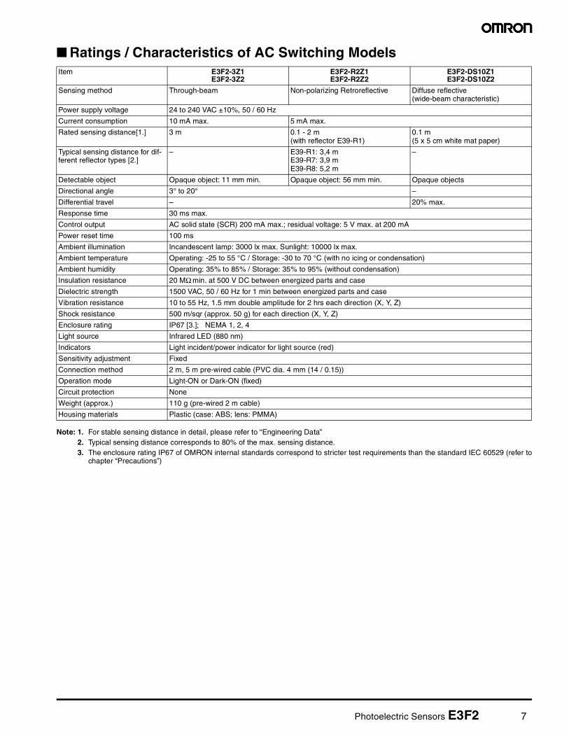
Ratings / Characteristics of AC Switching Models
Note: 1. For stable sensing distance in detail, please refer to “Engineering Data”2. Typical sensing distance corresponds to 80% of the max. sensing distance.3. The enclosure rating IP67 of OMRON internal standards correspond to stricter test requirements than the standard IEC 60529 (refer to
chapter “Precautions”)
Item E3F2-3Z1E3F2-3Z2
E3F2-R2Z1E3F2-R2Z2
E3F2-DS10Z1E3F2-DS10Z2
Sensing method Through-beam Non-polarizing Retroreflective Diffuse reflective (wide-beam characteristic)
Power supply voltage 24 to 240 VAC ±10%, 50 / 60 Hz
Current consumption 10 mA max. 5 mA max.
Rated sensing distance[1.] 3 m 0.1 - 2 m(with reflector E39-R1)
0.1 m (5 x 5 cm white mat paper)
Typical sensing distance for dif-ferent reflector types [2.]
– E39-R1: 3,4 mE39-R7: 3,9 mE39-R8: 5,2 m
–
Detectable object Opaque object: 11 mm min. Opaque object: 56 mm min. Opaque objects
Directional angle 3° to 20° –
Differential travel – 20% max.
Response time 30 ms max.
Control output AC solid state (SCR) 200 mA max.; residual voltage: 5 V max. at 200 mA
Power reset time 100 ms
Ambient illumination Incandescent lamp: 3000 lx max. Sunlight: 10000 lx max.
Ambient temperature Operating: -25 to 55 °C / Storage: -30 to 70 °C (with no icing or condensation)
Ambient humidity Operating: 35% to 85% / Storage: 35% to 95% (without condensation)
Insulation resistance 20 MΩ min. at 500 V DC between energized parts and case
Dielectric strength 1500 VAC, 50 / 60 Hz for 1 min between energized parts and case
Vibration resistance 10 to 55 Hz, 1.5 mm double amplitude for 2 hrs each direction (X, Y, Z)
Shock resistance 500 m/sqr (approx. 50 g) for each direction (X, Y, Z)
Enclosure rating IP67 [3.]; NEMA 1, 2, 4
Light source Infrared LED (880 nm)
Indicators Light incident/power indicator for light source (red)
Sensitivity adjustment Fixed
Connection method 2 m, 5 m pre-wired cable (PVC dia. 4 mm (14 / 0.15))
Operation mode Light-ON or Dark-ON (fixed)
Circuit protection None
Weight (approx.) 110 g (pre-wired 2 m cable)
Housing materials Plastic (case: ABS; lens: PMMA)
8 Photoelectric Sensors E3F2
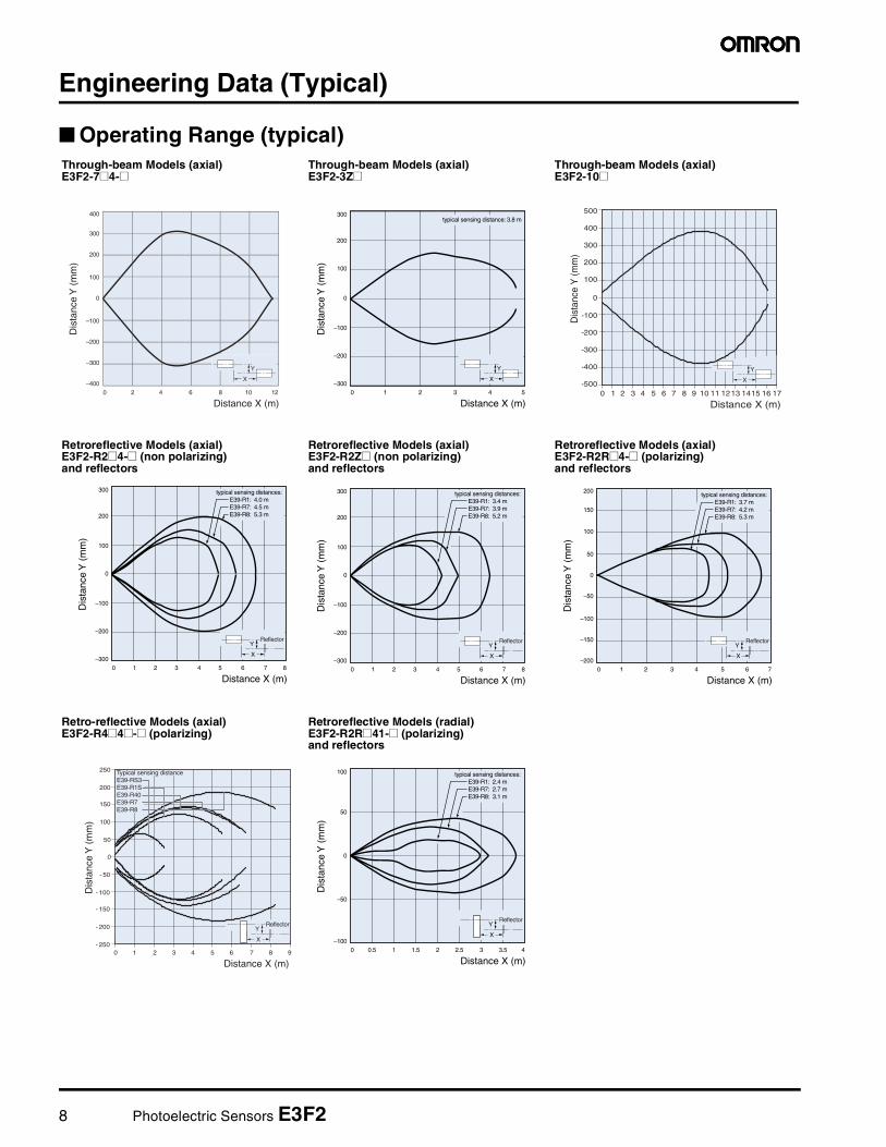
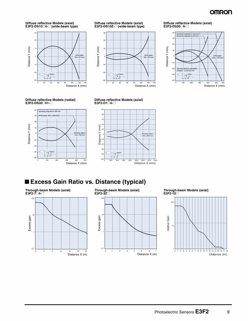
Engineering Data (Typical)
Operating Range (typical)Through-beam Models (axial)E3F2-7@4-@
Through-beam Models (axial)E3F2-3Z@
Through-beam Models (axial)E3F2-10@
Retroreflective Models (axial)E3F2-R2@4-@ (non polarizing)and reflectors
Retroreflective Models (axial)E3F2-R2Z@ (non polarizing)and reflectors
Retroreflective Models (axial)E3F2-R2R@4-@ (polarizing)and reflectors
Retro-reflective Models (axial)E3F2-R4@4@-@ (polarizing)
Retroreflective Models (radial)E3F2-R2R@41-@ (polarizing)and reflectors
1 2 3 4 50
0
100
200
300
–100
–200
–300
Dis
tanc
e Y
(m
m)
Distance X (m)
typical sensing distance: 3.8 m
X
Y
-500
-400
-300
-200
-100
0
100
200
300
400
500
0 1 2 3 4 5 6 7 8 9 10 11 1213 1415 16 17
Distance X (m)
Dis
tanc
e Y
(mm
)
X
Y
1 2 3 4 5 60
0
100
200
300
–100
–200
–300
Dis
tanc
e Y
(m
m)
Distance X (m)87
typical sensing distances:E39-R1: 4.0 mE39-R7: 4.5 mE39-R8: 5.3 m
X
YReflector
1 2 3 4 5 60
0
100
200
300
–100
–200
–300
Dis
tanc
e Y
(m
m)
Distance X (m)87
typical sensing distances:E39-R1: 3.4 mE39-R7: 3.9 mE39-R8: 5.2 m
X
YReflector
1 2 3 4 5 60
0
50
100
150
200
–50
–100
–150
–200
Dis
tanc
e Y
(m
m)
Distance X (m)
X
YReflector
7
typical sensing distances:E39-R1: 3.7 mE39-R7: 4.2 mE39-R8: 5.3 m
0
0 1 2 3 4 5 6 7 8 9
Distance X (m)
- 250
- 200
- 150
- 100
- 50
50
100
150
200
250
Dis
tanc
e Y
(m
m)
X
YReflector
Typical sensing distanceE39-RS3E39-R1SE39-R40E39-R7 E39-R8
0.5 1 1.5 2 2.5 30
0
50
100
–50
–100
Dis
tanc
e Y
(m
m)
Distance X (m)43.5
typical sensing distances:E39-R1: 2.4 mE39-R7: 2.7 mE39-R8: 3.1 m
X
YReflector
Photoelectric Sensors E3F2 9
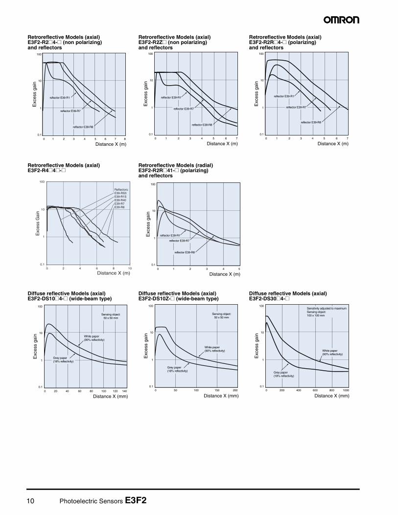
Excess Gain Ratio vs. Distance (typical)
Diffuse reflective Models (axial)E3F2-DS10@4-@ (wide-beam type)
Diffuse reflective Models (axial)E3F2-DS10Z-@ (wide-beam type)
Diffuse reflective Models (axial)E3F2-DS30@4-@
Diffuse reflective Models (radial)E3F2-DS30@41-@
Diffuse reflective Models (axial)E3F2-D1@4-@
Through-beam Models (axial)E3F2-7@4-@
Through-beam Models (axial)E3F2-3Z@
Through-beam Models (axial)E3F2-10@
20 40 60 80 100 1200
0
5
10
15
–5
–10
–15
Dis
tanc
e Y
(m
m)
Distance X (mm)140
white paper(50 x 50 mm)
X
YObject
20 40 60 80 100 1200
0
10
20
30
–10
–20
–30
Dis
tanc
e Y
(m
m)
Distance X (mm)140
white paper(50 x 50 mm)
X
YObject
100 200 300 400 500 6000
0
10
20
30
40
–10
–20
–30
–40
Dis
tanc
e Y
(m
m)
Distance X (mm)
Sensing distance adjustablebetween 0 and 550 mm
Sensitivity adjusted to maximumSensitivity adjusted to 400 mm
white paper(100 x 100 mm)
X
YObject
100 200 300 400 5000
0
10
20
30
40
–10
–20
–30
–40
Dis
tanc
e Y
(m
m)
Distance X (mm)
Sensitivity adjusted to 390 mm
White paper (90% reflectivity)
Sensing object:100 x 100 mm
X
YObject
100
80
60
40
20
0
-20
-40
-60
-80
-1000 200 400 600 800 1000 1200 1400 1600
Distance X (mm)
Dis
tanc
e Y
(m
m)
Sensing object:300 x 300 mm
X
YObject
2 4 6 8 10 120
100
10
1
0.1
Exc
ess
gain
Distance X (m)1 2 3 4 5 60
100
10
1
0.1
Exc
ess
gain
Distance X (m)7
1
10
100
0 1 2 3 4 5 6 7 8 9 10 11 12 13 14 15 16 17 18
Distance [m]
rela
tive
Gai
n
10 Photoelectric Sensors E3F2
Retroreflective Models (axial)E3F2-R2@4-@ (non polarizing)and reflectors
Retroreflective Models (axial)E3F2-R2Z@ (non polarizing)and reflectors
Retroreflective Models (axial)E3F2-R2R@4-@ (polarizing)and reflectors
Retroreflective Models (axial)E3F2-R4@4@-@
Retroreflective Models (radial)E3F2-R2R@41-@ (polarizing)and reflectors
Diffuse reflective Models (axial)E3F2-DS10@4-@ (wide-beam type)
Diffuse reflective Models (axial)E3F2-DS10Z-@ (wide-beam type)
Diffuse reflective Models (axial)E3F2-DS30@4-@
1 2 3 4 5 60
100
10
1
0.1
Exc
ess
gain
Distance X (m)7 8
reflector E39-R7
reflector E39-R1
reflector E39-R8
1 2 3 4 5 60
100
10
1
0.1
Exc
ess
gain
Distance X (m)7
reflector E39-R1
reflector E39-R7
reflector E39-R8
1 2 3 4 5 60
100
10
1
0.1
Exc
ess
gain
Distance X (m)7
reflector E39-R1
reflector E39-R7
reflector E39-R8
0.1
1
10
100
0 2 4 6 8 10
Distance X (m)
Exc
ess
Gai
n
Reflectors:E39-RS3E39-R1SE39-R40E39-R7E39-R8
1 2 3 4 50
100
10
1
0.1
Exc
ess
gain
Distance X (m)
reflector E39-R1
reflector E39-R7
reflector E39-R8
20 40 60 80 100 1200
100
10
1
0.1
Exc
ess
gain
Distance X (mm)140
Grey paper(18% reflectivity)
Sensing object:50 x 50 mm
White paper(90% reflectivity)
50 100 1500
100
10
1
0.1
Exc
ess
gain
Distance X (mm)200
Grey paper(18% reflectivity)
Sensing object:50 x 50 mm
White paper(90% reflectivity)
200 400 600 800 10000
100
10
1
0.1
Exc
ess
gain
Distance X (mm)
Grey paper(18% reflectivity)
White paper(90% reflectivity)
Sensitivity adjusted to maximumSensing object:100 x 100 mm
Photoelectric Sensors E3F2 11
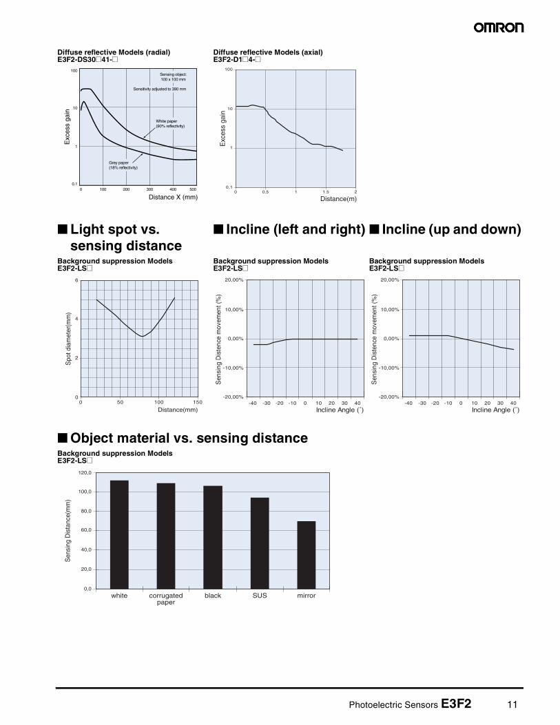
Diffuse reflective Models (radial)E3F2-DS30@41-@
Diffuse reflective Models (axial)E3F2-D1@4-@
Light spot vs. sensing distance
Incline (left and right) Incline (up and down)
Background suppression ModelsE3F2-LS@
Background suppression ModelsE3F2-LS@
Background suppression ModelsE3F2-LS@
Object material vs. sensing distanceBackground suppression ModelsE3F2-LS@
100 200 300 400 5000
100
10
1
0.1
Exc
ess
gain
Distance X (mm)
Grey paper(18% reflectivity)
Sensing object:100 x 100 mm
White paper(90% reflectivity)
Sensitivity adjusted to 390 mm
0,1
1
10
100
Distance(m)
Exc
ess
gain
0 0.5 1 1.5 2
0
2
4
6
0 50 100 150
Distance(mm)
Spo
t dia
met
er(m
m)
-20,00%
-10,00%
0,00%
10,00%
20,00%
-40 -30 -20 -10 0 10 20 30 40
Incline Angle (˚)
Sen
sing
Dis
tenc
e m
ovem
ent (
%)
-20,00%
-10,00%
0,00%
10,00%
20,00%
-40 -30 -20 -10 0 10 20 30 40
Incline Angle (˚)
Sen
sing
Dis
tenc
e m
ovem
ent (
%)
0,0
20,0
40,0
60,0
80,0
100,0
120,0
white corrugated paper
black SUS mirror
Sen
sing
Dis
tanc
e(m
m)

12 Photoelectric Sensors E3F2
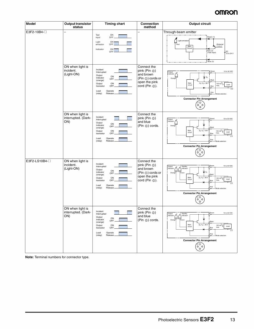
Operation
Output Circuits
Structure of Sensor I/O Connector
PNP Output
Classification Wire color Connector pin No.
Use
DC Brown Power supply (+V)
White Mode selection Lon/Don
Blue Power supply (0 V)
Black Output
1
2
3
4
1234
BrownWhiteBlueBlack
XS2F-D42#-D80-#XS2F-G42#-G80-#
Model Output transistor status
Timing chart Connection method
Output circuit
E3F2-@B4-@(except for E3F2-10B4-@ and E3F2-LS10B4-@)
– – – Through-beam emitter
ON when light is incident. (Light-ON)
Connect the pink (Pin ) and brown (Pin ) cords or open the pink cord (Pin ).
ON when light is interrupted. (Dark-ON)
Connect the pink (Pin ) and blue (Pin ) cords.
Maincircuit
12
34
1
3
Connector Pin Arrangement
10 to 30 VDC
0 V
Brown
Blue
Powerindicator(red)
IncidentInterrupted
ONOFF
ONOFF
OperateRelease
Outputindicator(red)
Outputtransistor
Load(relay)
2
1
2
Lightindicator
Red
Maincircuit
12
34
1
2
3
4
Connector Pin Arrangement
10 to 30 VDC
100 mAmax.
Load
0 V
Mode selection
Brown
Black
Blue
Pink
ZD
ZD: VZ = 36 V
Stability indicator*
Green
* Only on modelsE3F2-R4B4-@ andE3F2-D1B4-@
IncidentInterrupted
ONOFF
ONOFF
OperateRelease
Outputindicator(red)
Outputtransistor
Load(relay)
2
3
Lightindicator
Red
Maincircuit
12
34
1
2
3
4
Connector Pin Arrangement
10 to 30 VDC
100 mAmax.
Load
0 V
Mode selection
Brown
Black
Blue
Pink
ZD: VZ = 36 V
Stability indicator*
Green
* Only on modelsE3F2-R4B4-@ andE3F2-D1B4-@
Photoelectric Sensors E3F2 13
Note: Terminal numbers for connector type.
E3F2-10B4-@ – – Through-beam emitter
ON when light is incident. (Light-ON)
Connect the pink (Pin ) and brown (Pin ) cords or open the pink cord (Pin ).
ON when light is interrupted. (Dark-ON)
Connect the pink (Pin ) and blue (Pin ) cords.
E3F2-LS10B4-@ ON when light is incident. (Light-ON)
Connect the pink (Pin ) and brown (Pin ) cords or open the pink cord (Pin ).
ON when light is interrupted. (Dark-ON)
Connect the pink (Pin ) and blue (Pin ) cords.
Model Output transistor status
Timing chart Connection method
Output circuit
ONOFF
ONOFF
ONOFF
Testinput
Light emission
Indicator
Red
IncidentInterrupted
ONOFF
ONOFF
OperateRelease
Outputindicator(orange)
Outputtransistor
Load(relay)
2
1
2
Outputindicator
Orange
Maincircuit
12
34
1
2
3
4
Connector Pin Arrangement
10 to 30 VDC
100 mAmax.
Load
0 V
Mode selection
Brown
Black
Blue
Pink
ZD: VZ = 36 V
ZD
IncidentInterrupted
ONOFF
ONOFF
OperateRelease
Outputindicator(orange)
Outputtransistor
Load(relay)
2
3
Outputindicator
Orange
Maincircuit
12
34
1
2
3
4
Connector Pin Arrangement
10 to 30 VDC
100 mAmax.
Load
0 V
Mode selection
Brown
Black
Blue
Pink
ZD: VZ = 36 V
IncidentInterrupted
ONOFF
ONOFF
OperateRelease
Outputindicator(orange)
Outputtransistor
Load(relay)
2
1
2
Outputindicator
Stabilityindicator*
Orange
Maincircuit
12
34
1
2
3
4
Connector Pin Arrangement
10 to 30 VDC
100 mAmax.
Load
0 V
Mode selection
Brown
Black
Blue
Pink
ZD
ZD: VZ = 36 V
Green
IncidentInterrupted
ONOFF
ONOFF
OperateRelease
Outputindicator(orange)
Outputtransistor
Load(relay)
2
3
Outputindicator
Stabilityindicator*
Orange
Maincircuit
12
34
1
2
3
4
Connector Pin Arrangement
10 to 30 VDC
100 mAmax.
Load
0 V
Mode selection
Brown
Black
Blue
Pink
ZD: VZ = 36 V
Green
14 Photoelectric Sensors E3F2
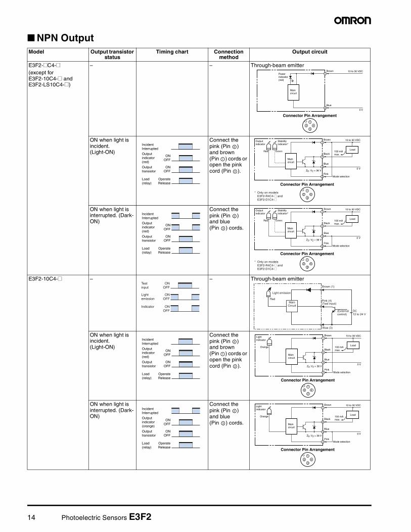
NPN OutputModel Output transistor
statusTiming chart Connection
methodOutput circuit
E3F2-@C4-@(except for E3F2-10C4-@ and E3F2-LS10C4-@)
– – Through-beam emitter
ON when light is incident. (Light-ON)
Connect the pink (Pin ) and brown (Pin ) cords or open the pink cord (Pin ).
ON when light is interrupted. (Dark-ON)
Connect the pink (Pin ) and blue (Pin ) cords.
E3F2-10C4-@ – – Through-beam emitter
ON when light is incident. (Light-ON)
Connect the pink (Pin ) and brown (Pin ) cords or open the pink cord (Pin ).
ON when light is interrupted. (Dark-ON)
Connect the pink (Pin ) and blue (Pin ) cords.
Maincircuit
12
34
1
3
Connector Pin Arrangement
10 to 30 VDC
0 V
Brown
Blue
Powerindicator(red)
IncidentInterrupted
ONOFF
ONOFF
OperateRelease
Outputindicator(red)
Outputtransistor
Load(relay)
2
1
2
Outputindicator
Red
Maincircuit
12
34
1
2
3
4
Connector Pin Arrangement
10 to 30 VDC
100 mAmax.
Load
0 V
Mode selection
Brown
Black
Blue
PinkZD: VZ = 36 V
Stabilityindicator*
Green
* Only on modelsE3F2-R4C4-@ andE3F2-D1C4-@
IncidentInterrupted
ONOFF
ONOFF
OperateRelease
Outputindicator(red)
Outputtransistor
Load(relay)
2
3
Outputindicator
Red
Maincircuit
12
34
1
2
3
4
Connector Pin Arrangement
10 to 30 VDC
100 mAmax.
Load
0 V
Mode selection
Brown
Black
Blue
PinkZD: VZ = 36 V
Stabilityindicator*
Green
* Only on modelsE3F2-R4C4-@ andE3F2-D1C4-@
ONOFF
ONOFF
ONOFF
Testinput
Light emission
Indicator
Red
IncidentInterrupted
ONOFF
ONOFF
OperateRelease
Outputindicator(red)
Outputtransistor
Load(relay)
2
1
2
Lightindicator
Orange
Maincircuit
12
34
1
2
3
4
Connector Pin Arrangement
10 to 30 VDC
100 mAmax.
Load
0 V
Mode selection
Brown
Black
Blue
PinkZD: VZ = 36 V
IncidentInterrupted
ONOFF
ONOFF
OperateRelease
Outputindicator(orange)
Outputtransistor
Load(relay)
2
3
Lightindicator
Orange
Maincircuit
12
34
1
2
3
4
Connector Pin Arrangement
10 to 30 VDC
100 mAmax.
Load
0 V
Mode selection
Brown
Black
Blue
PinkZD: VZ = 36 V
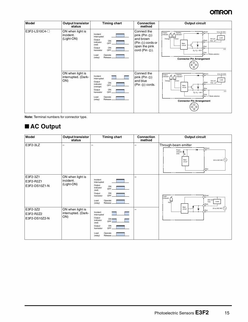
Photoelectric Sensors E3F2 15
Note: Terminal numbers for connector type.
AC Output
E3F2-LS10C4-@ ON when light is incident. (Light-ON)
Connect the pink (Pin ) and brown (Pin ) cords or open the pink cord (Pin ).
ON when light is interrupted. (Dark-ON)
Connect the pink (Pin ) and blue (Pin ) cords.
Model Output transistor status
Timing chart Connection method
Output circuit
IncidentInterrupted
ONOFF
ONOFF
OperateRelease
Outputindicator(red)
Outputtransistor
Load(relay)
2
1
2
Outputindicator
Orange
Maincircuit
12
34
1
2
3
4
Connector Pin Arrangement
10 to 30 VDC
100 mAmax.
Load
0 V
Mode selection
Brown
Black
Blue
PinkZD: VZ = 36 V
Stabilityindicator*
Green
IncidentInterrupted
ONOFF
ONOFF
OperateRelease
Outputindicator(orange)
Outputtransistor
Load(relay)
2
3
Outputindicator
Orange
Maincircuit
12
34
1
2
3
4
Connector Pin Arrangement
10 to 30 VDC
100 mAmax.
Load
0 V
Mode selection
Brown
Black
Blue
PinkZD: VZ = 36 V
Stabilityindicator*
Green
Model Output transistor status
Timing chart Connection method
Output circuit
E3F2-3LZ – – – Through-beam emitter
E3F2-3Z1E3F2-R2Z1E3F2-DS10Z1-N
ON when light is incident. (Light-ON)
–
E3F2-3Z2E3F2-R2Z2E3F2-DS10Z2-N
ON when light is interrupted. (Dark-ON)
–
Maincircuit
24 to 240 VAC
Brown
Blue
Powerindicator(red)
IncidentInterrupted
ONOFF
ONOFF
OperateRelease
Outputindicator(red)
Outputtransistor
Load(relay)
Lightindicator
Red
Maincircuit
200 mAmax. Load
Brown
Black
Blue24 to 240 VAC
IncidentInterrupted
ONOFF
ONOFF
OperateRelease
Outputindicator(red)
Outputtransistor
Load(relay)
16 Photoelectric Sensors E3F2
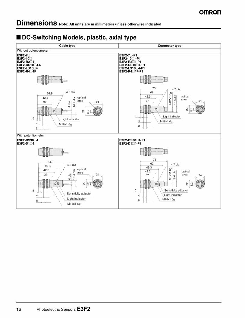
Dimensions Note: All units are in millimeters unless otherwise indicated
DC-Switching Models, plastic, axial typeCable type Connector type
Without potentiometer
E3F2-7@E3F2-10@E3F2-R2@4E3F2-DS10@4-NE3F2-LS10@4E3F2-R4@4F
E3F2-7@-P1E3F2-10@ –P1E3F2-R2@4-P1E3F2-DS10@4-P1E3F2-LS10@4-P1E3F2-R4@4F-P1
With potentiometer
E3F2-DS30@4E3F2-D1@4
E3F2-DS30@4-P1E3F2-D1@4-P1
4.8 dia
37
42.3
64.9
M18x1 6g
Light indicator5
4
8
16.4
dia
6.222
24
4 di
a
opticalarea
5
4
8
M18x1 6g
Light indicator
4.7 dia
42.3
37
M12
x1 6
g
16.6
dia
73
6.222
24
62opticalarea
37
42.349.3
M18x1 6g
Light indicator
Sensitivity adjustor5
4
8
16.4
dia
4.8 dia
6.222
24
64.9
4 di
a
opticalarea
5
4
8 M18x1 6g
Sensitivity adjustor
Light indicator
4.7 dia49.3
42.337
M12
x1 6
g
16.6
dia
73
6.222
24
62
opticalarea
Photoelectric Sensors E3F2 17
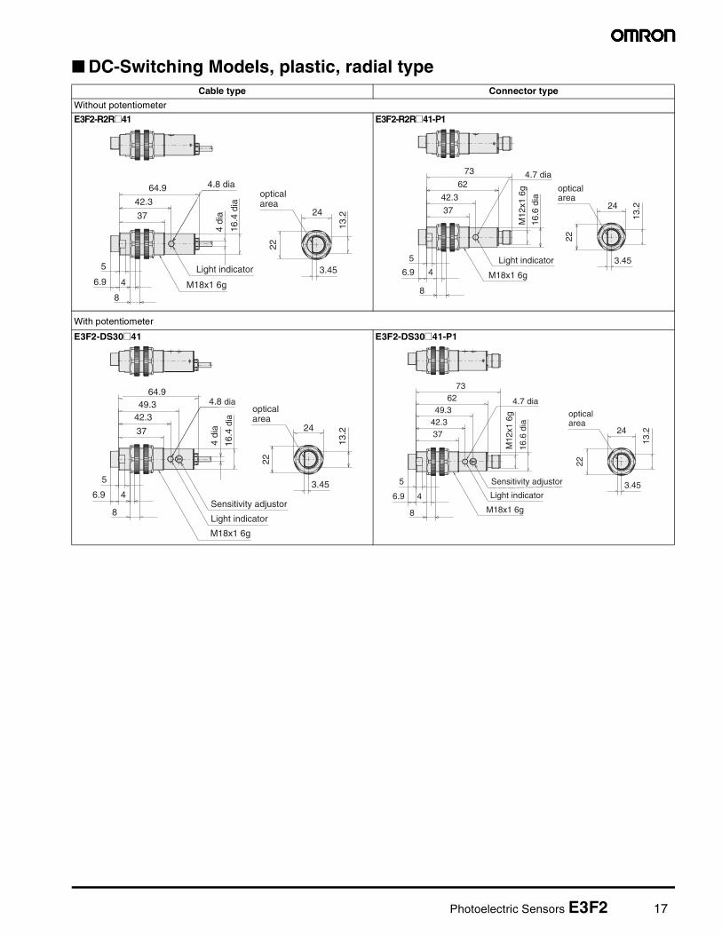
DC-Switching Models, plastic, radial typeCable type Connector type
Without potentiometer
E3F2-R2R@41 E3F2-R2R@41-P1
With potentiometer
E3F2-DS30@41 E3F2-DS30@41-P1
37
42.3
64.9
M18x1 6g
Light indicator5
4
8
16.4
dia
4.8 dia
4 di
a
6.93.45
24
22
opticalarea
13.2
5
4
8
M18x1 6g
Light indicator
4.7 dia
42.3
37
M12
x1 6
g
16.6
dia
73
62
6.9
opticalarea
24
13.2
22
3.45
37
42.349.3
M18x1 6g
Light indicator
Sensitivity adjustor
5
4
8
16.4
dia
4.8 dia64.9
4 di
a
6.9
opticalarea
24
22
3.45
13.2
5
4
8 M18x1 6g
Sensitivity adjustor
Light indicator
4.7 dia49.3
42.337
M12
x1 6
g
16.6
dia
7362
6.9
opticalarea
24
13.2
3.45
22
18 Photoelectric Sensors E3F2
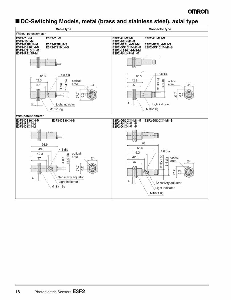
DC-Switching Models, metal (brass and stainless steel), axial typeCable type Connector type
Without potentiometer
E3F2-7@-M E3F2-7@-SE3F2-10@-ME3F2-R2R@4-M E3F2-R2R@4-SE3F2-DS10@4-M E3F2-DS10@4-SE3F2-LS10@4-ME3F2-R4@4F-M
E3F2-7@-M1-M E3F2-7@-M1-SE3F2-10@-M1-ME3F2-R2R@4-M1-M E3F2-R2R@4-M1-S E3F2-DS10@4-M1-M E3F2-DS10@4-M1-SE3F2-LS10@4-M1-ME3F2-R4@4F-M1-M
With potentiometer
E3F2-DS30@4-M E3F2-DS30@4-SE3F2-R4@4-ME3F2-D1@4-M
E3F2-DS30@4-M1-M E3F2-DS30@4-M1-SE3F2-R4@4-M1-ME3F2-D1@4-M1-M
4.8 dia
37
42.3
64.9
Light indicator
16.4
dia
4 di
a
4
M18x1 6g
24
27.7
6.2
opticalarea 37
42.3
Light indicator
4.8 dia76
16.4
dia
M12
x1 6
g
4
M18x1 6g
24
27.7
6.2
65.5
opticalarea
37
42.3
49.3
64.9
Light indicator
Sensitivity adjustor
4.8 dia
16.4
dia
4 di
a
4
M18x1 6g
24
27.7
6.2
opticalarea
37
42.3
49.3
Light indicator
Sensitivity adjustor
4.8 dia
16.4
dia
M12
x1 6
g
4
M18x1 6g
76
65.5
24
27.7
6.2
opticalarea
Photoelectric Sensors E3F2 19
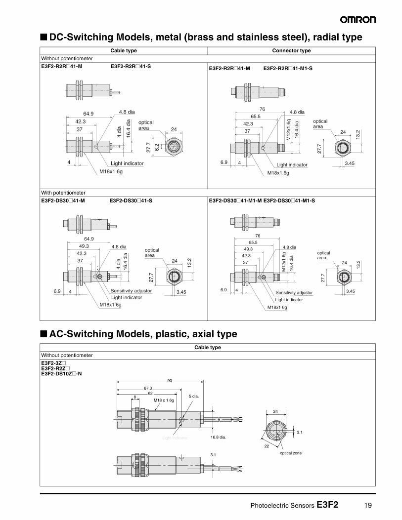
DC-Switching Models, metal (brass and stainless steel), radial type
AC-Switching Models, plastic, axial type
Cable type Connector type
Without potentiometer
E3F2-R2R@41-M E3F2-R2R@41-S E3F2-R2R@41-M E3F2-R2R@41-M1-S
With potentiometer
E3F2-DS30@41-M E3F2-DS30@41-S E3F2-DS30@41-M1-M E3F2-DS30@41-M1-S
Cable type
Without potentiometer
E3F2-3Z@E3F2-R2Z@E3F2-DS10Z@-N
4.8 dia
37
42.3
64.9
Light indicator
16.4
dia
4 di
a
4
M18x1 6g
24
27.7
6.2
opticalarea
37
42.3
Light indicator
4.8 dia76
16.4
dia
M12
x1.6
g
4
M18x1.6g
65.5
6.9
24
27.7
3.45
13.2
opticalarea
37
42.3
49.3
64.9
Light indicatorSensitivity adjustor
4.8 dia
16.4
dia
4 di
a
4
M18x1 6g
6.9
opticalarea
24
3.45
27.7
13.2 37
42.3
49.3
Light indicator
Sensitivity adjustor
4.8 dia
16.4
dia
M12
x1 6
g
4
M18x1 6g
76
65.5
6.9
opticalarea
24
13.2
27.7
3.45
16.8 dia.
24
3.1
optical zone
22
90
67.362
M18 x 1 6g5 dia.8
3.1
Light indicator
20 Photoelectric Sensors E3F2
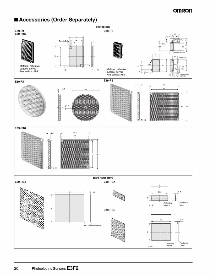
Accessories (Order Separately)Reflectors
E39-R1E39-R1S
E39-R3
E39-R7 E39-R8
E39-R40
Material, reflective surface: acrylicRear surface: ABS
34
40.3
5259.9
2.7
8
1.6
7.57
Two, 3.5 dia.
29
4.5 6
R203.4
7
18.45
22.9
11
200.2
0.2
16
22.5
19.3
343834.82-M341.8
10.1 1.2
25.4 R25.43.4
10˚1.22.6 Stainless steel
(SUS304)
Adhesive tape side
Two, 3.2 dia.
13.714˚
3.4
Material, reflective surface: acrylicRear surface: ABS
4.5
847.4
ffor M3for M3
9 100
100
92
92
for M3
8.7 84.5
84.5
77
77
Tape Reflectors
E39-RS3 E39-RSA
E39-RSB
80
4-R1
70
0.6
Adhesive tape side
35
10
0.7
Adhesive tape
Reflectingsurface4 x R1
40
35
0.7
Adhesivetape
Reflectingsurface4 x R1

Photoelectric Sensors E3F2 21
Installation
Mounting BracketY92E-B18
Note: Hexagon bolt: M5 x 32Material: plastic
Lens CapE39-F31
Mounting BracketY92E-G18
Slit (for precision detection with E3F2-10@) E39-ES18
20 dia.
4 max.
Metal rim Gasket E3F2
Glass plate
Approx. 35
23.520.5530
Two tightening nuts30
M24x1.5
Sensor tightening nut30
30
16
1
21 4
22 Photoelectric Sensors E3F2
PrecautionsThe E3F2 Photoelectric Sensor is not a safety component for ensur-ing the safety of people which is defined in EC directive (91/368/EEC) and covered by separate European standards or by any otherregulations or standards.
Degree of protectionThe E3F2 photoelectric sensors have a degree of protection ratedwith IP67. In this case, the sensors have passed the OMRON heatshock test before the IP67-test of IEC 60529 (submersion at 1mwater depth for 30 min). Afterwards the sensors have been testedaccording to the OMRON waterproof test.
Heat shock: The Alternating, fast temperature changes between -25°C and +55°C are executed for 5 cycles and 1 hour for each temperature. Function and isolation are checked.
Water proof: The sensors are submerged alternating in water of +2°C and +55°C. 20 cycles with 1 hour for each tem-perature are executed. Function, water tightness and electrical isolation are checked.
Do not expose the photoelectric sensor to excessive shock duringinstallation, keeping within IP 67 standards.
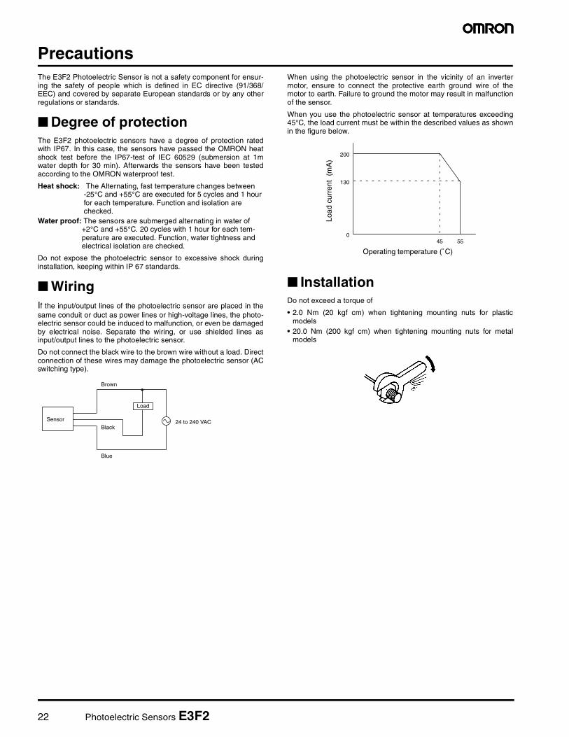
WiringIf the input/output lines of the photoelectric sensor are placed in thesame conduit or duct as power lines or high-voltage lines, the photo-electric sensor could be induced to malfunction, or even be damagedby electrical noise. Separate the wiring, or use shielded lines asinput/output lines to the photoelectric sensor.
Do not connect the black wire to the brown wire without a load. Directconnection of these wires may damage the photoelectric sensor (ACswitching type).
When using the photoelectric sensor in the vicinity of an invertermotor, ensure to connect the protective earth ground wire of themotor to earth. Failure to ground the motor may result in malfunctionof the sensor.
When you use the photoelectric sensor at temperatures exceeding45°C, the load current must be within the described values as shownin the figure below.
InstallationDo not exceed a torque of
• 2.0 Nm (20 kgf cm) when tightening mounting nuts for plasticmodels
• 20.0 Nm (200 kgf cm) when tightening mounting nuts for metalmodels
Black
Brown
Blue
Load
Sensor 24 to 240 VAC
Operating temperature (˚C)
200
130
55450
Load
cur
rent
(m
A)
Photoelectric Sensors E3F2 23
Certain Terms and Conditions of Sale1. Offer; Acceptance. These terms and conditions (these "Terms") are deemed
part of all catalogs, manuals or other documents, whether electronic or in writ-ing, relating to the sale of goods or services (collectively, the "Goods") byOmron Electronics LLC and its subsidiary companies ("Seller"). Seller herebyobjects to any terms or conditions proposed in Buyer's purchase order or otherdocuments which are inconsistent with, or in addition to, these Terms. Pleasecontact your Omron representative to confirm any additional terms for salesfrom your Omron company.
2. Prices. All prices stated are current, subject to change without notice bySeller. Buyer agrees to pay the price in effect at time of shipment.
3. Discounts. Cash discounts, if any, will apply only on the net amount ofinvoices sent to Buyer after deducting transportation charges, taxes andduties, and will be allowed only if (i) the invoice is paid according to Seller'spayment terms and (ii) Buyer has no past due amounts owing to Seller.
4. Orders. Seller will accept no order less than $200 net billing. 5. Governmental Approvals. Buyer shall be responsible for, and shall bear all
costs involved in, obtaining any government approvals required for the impor-tation or sale of the Goods.
6. Taxes. All taxes, duties and other governmental charges (other than generalreal property and income taxes), including any interest or penalties thereon,imposed directly or indirectly on Seller or required to be collected directly orindirectly by Seller for the manufacture, production, sale, delivery, importation,consumption or use of the Goods sold hereunder (including customs dutiesand sales, excise, use, turnover and license taxes) shall be charged to andremitted by Buyer to Seller.
7. Financial. If the financial position of Buyer at any time becomes unsatisfactoryto Seller, Seller reserves the right to stop shipments or require satisfactorysecurity or payment in advance. If Buyer fails to make payment or otherwisecomply with these Terms or any related agreement, Seller may (without liabilityand in addition to other remedies) cancel any unshipped portion of Goods soldhereunder and stop any Goods in transit until Buyer pays all amounts, includ-ing amounts payable hereunder, whether or not then due, which are owing to itby Buyer. Buyer shall in any event remain liable for all unpaid accounts.
8. Cancellation; Etc. Orders are not subject to rescheduling or cancellationunless Buyer indemnifies Seller fully against all costs or expenses arising inconnection therewith.
9. Force Majeure. Seller shall not be liable for any delay or failure in deliveryresulting from causes beyond its control, including earthquakes, fires, floods,strikes or other labor disputes, shortage of labor or materials, accidents tomachinery, acts of sabotage, riots, delay in or lack of transportation or therequirements of any government authority.
10. Shipping; Delivery. Unless otherwise expressly agreed in writing by Seller:a. Shipments shall be by a carrier selected by Seller;b. Such carrier shall act as the agent of Buyer and delivery to such carrier
shall constitute delivery to Buyer;c. All sales and shipments of Goods shall be FOB shipping point (unless oth-
erwise stated in writing by Seller), at which point title to and all risk of loss ofthe Goods shall pass from Seller to Buyer, provided that Seller shall retain asecurity interest in the Goods until the full purchase price is paid by Buyer;
d. Delivery and shipping dates are estimates only. e. Seller will package Goods as it deems proper for protection against normal
handling and extra charges apply to special conditions.11. Claims. Any claim by Buyer against Seller for shortage or damage to the
Goods occurring before delivery to the carrier must be presented in writing toSeller within 30 days of receipt of shipment and include the original transporta-tion bill signed by the carrier noting that the carrier received the Goods fromSeller in the condition claimed.
12. Warranties. (a) Exclusive Warranty. Seller's exclusive warranty is that theGoods will be free from defects in materials and workmanship for a period oftwelve months from the date of sale by Seller (or such other period expressedin writing by Seller). Seller disclaims all other warranties, express or implied.(b) Limitations. SELLER MAKES NO WARRANTY OR REPRESENTATION,EXPRESS OR IMPLIED, ABOUT NON-INFRINGEMENT, MERCHANTABIL-ITY OR FITNESS FOR A PARTICULAR PURPOSE OF THE GOODS.BUYER ACKNOWLEDGES THAT IT ALONE HAS DETERMINED THAT THEGOODS WILL SUITABLY MEET THE REQUIREMENTS OF THEIRINTENDED USE. Seller further disclaims all warranties and responsibility ofany type for claims or expenses based on infringement by the Goods or other-wise of any intellectual property right. (c) Buyer Remedy. Seller's sole obliga-tion hereunder shall be to replace (in the form originally shipped with Buyerresponsible for labor charges for removal or replacement thereof) the non-complying Good or, at Seller's election, to repay or credit Buyer an amountequal to the purchase price of the Good; provided that in no event shall Sellerbe responsible for warranty, repair, indemnity or any other claims or expensesregarding the Goods unless Seller's analysis confirms that the Goods wereproperly handled, stored, installed and maintained and not subject to contami-nation, abuse, misuse or inappropriate modification. Return of any goods byBuyer must be approved in writing by Seller before shipment. Seller shall notbe liable for the suitability or unsuitability or the results from the use of Goodsin combination with any electrical or electronic components, circuits, systemassemblies or any other materials or substances or environments. Anyadvice, recommendations or information given orally or in writing, are not to beconstrued as an amendment or addition to the above warranty.
13. Damage Limits; Etc. SELLER SHALL NOT BE LIABLE FOR SPECIAL, INDI-RECT OR CONSEQUENTIAL DAMAGES, LOSS OF PROFITS OR PRODUC-TION OR COMMERCIAL LOSS IN ANY WAY CONNECTED WITH THEGOODS, WHETHER SUCH CLAIM IS BASED IN CONTRACT, WARRANTY,NEGLIGENCE OR STRICT LIABILITY. Further, in no event shall liability ofSeller exceed the individual price of the Good on which liability is asserted.
14. Indemnities. Buyer shall indemnify and hold harmless Seller, its affiliates andits employees from and against all liabilities, losses, claims, costs andexpenses (including attorney's fees and expenses) related to any claim, inves-tigation, litigation or proceeding (whether or not Seller is a party) which arisesor is alleged to arise from Buyer's acts or omissions under these Terms or inany way with respect to the Goods. Without limiting the foregoing, Buyer (atits own expense) shall indemnify and hold harmless Seller and defend or settleany action brought against Seller to the extent that it is based on a claim thatany Good made to Buyer specifications infringed intellectual property rights ofanother party.
15. Property; Confidentiality. The intellectual property embodied in the Goods isthe exclusive property of Seller and its affiliates and Buyer shall not attempt toduplicate it in any way without the written permission of Seller. Notwithstand-ing any charges to Buyer for engineering or tooling, all engineering and toolingshall remain the exclusive property of Seller. All information and materialssupplied by Seller to Buyer relating to the Goods are confidential and propri-etary, and Buyer shall limit distribution thereof to its trusted employees andstrictly prevent disclosure to any third party.
16. Miscellaneous. (a) Waiver. No failure or delay by Seller in exercising any rightand no course of dealing between Buyer and Seller shall operate as a waiverof rights by Seller. (b) Assignment. Buyer may not assign its rights hereunderwithout Seller's written consent. (c) Amendment. These Terms constitute theentire agreement between Buyer and Seller relating to the Goods, and no pro-vision may be changed or waived unless in writing signed by the parties. (d) Severability. If any provision hereof is rendered ineffective or invalid, suchprovision shall not invalidate any other provision. (e) Setoff. Buyer shall haveno right to set off any amounts against the amount owing in respect of thisinvoice. (f) As used herein, "including" means "including without limitation".
Certain Precautions on Specifications and Use1. Suitability of Use. Seller shall not be responsible for conformity with any stan-
dards, codes or regulations which apply to the combination of the Good in theBuyer's application or use of the Good. At Buyer's request, Seller will provideapplicable third party certification documents identifying ratings and limitationsof use which apply to the Good. This information by itself is not sufficient for acomplete determination of the suitability of the Good in combination with theend product, machine, system, or other application or use. The following aresome examples of applications for which particular attention must be given.This is not intended to be an exhaustive list of all possible uses of this Good,nor is it intended to imply that the uses listed may be suitable for this Good: (i) Outdoor use, uses involving potential chemical contamination or electrical
interference, or conditions or uses not described in this document. (ii) Energy control systems, combustion systems, railroad systems, aviation
systems, medical equipment, amusement machines, vehicles, safety equipment, and installations subject to separate industry or governmentregulations.
(iii) Systems, machines and equipment that could present a risk to life orproperty. Please know and observe all prohibitions of use applicable tothis Good.
NEVER USE THE PRODUCT FOR AN APPLICATION INVOLVING SERIOUSRISK TO LIFE OR PROPERTY WITHOUT ENSURING THAT THE SYSTEMAS A WHOLE HAS BEEN DESIGNED TO ADDRESS THE RISKS, AND THATTHE SELLER'S PRODUCT IS PROPERLY RATED AND INSTALLED FORTHE INTENDED USE WITHIN THE OVERALL EQUIPMENT OR SYSTEM.
2. Programmable Products. Seller shall not be responsible for the user's programming of a programmable Good, or any consequence thereof.
3. Performance Data. Performance data given in this catalog is provided as aguide for the user in determining suitability and does not constitute a warrantyIt may represent the result of Seller's test conditions, and the user must correlate it to actual application requirements. Actual performance is subject to theSeller's Warranty and Limitations of Liability.
4. Change in Specifications. Product specifications and accessories may bechanged at any time based on improvements and other reasons. It is our practice to change part numbers when published ratings or features are changedor when significant construction changes are made. However, some specifications of the Good may be changed without any notice. When in doubt, speciapart numbers may be assigned to fix or establish key specifications for youapplication. Please consult with your Seller's representative at any time to confirm actual specifications of purchased Good.
5. Errors and Omissions. The information in this catalog has been carefullychecked and is believed to be accurate; however, no responsibility is assumedfor clerical, typographical or proofreading errors, or omissions.
24 Photoelectric Sensors E3F2
OMRON ON-LINEGlobal - http://www.omron.comUSA - http://www.omron.com/oeiCanada - http://www.omron.ca
Cat. No. E224-E3-04 Printed in USA
OMRON CANADA, INC.885 Milner AvenueToronto, Ontario M1B 5V8
416-286-6465
OMRON ELECTRONICS LLCOne Commerce DriveSchaumburg, IL 60173
847-843-7900For US technical support or other inquiries:
800-556-676604/05 Specifications subject to change without notice
Complete “Terms and Conditions of Sale” for product purchase and use are on Omron’s websiteat www.omron.com/oei – under the “About Us” tab, in the Legal Matters section.
ALL DIMENSIONS SHOWN ARE IN MILLIMETERS.To convert millimeters into inches, multiply by 0.03937. To convert grams into ounces, multiply by 0.03527.