earthing philosophy reference standards legend: …
TRANSCRIPT
1
2
3
4
ECC
GPR
PEN
MV
LV
NOTES:
1)
2)
3)
4)
5)
6)
7)
8)
Medium Voltage
Low Voltage
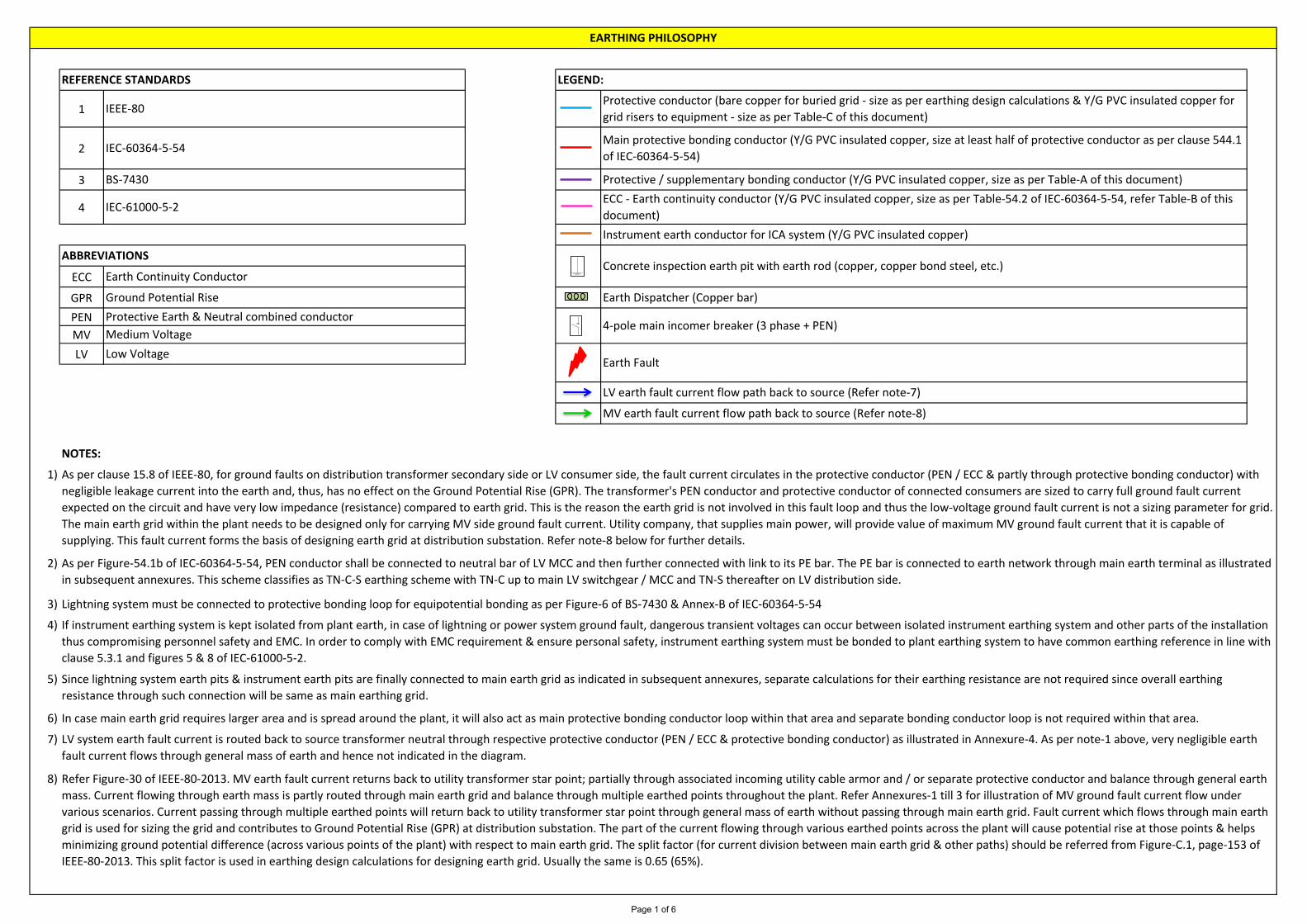
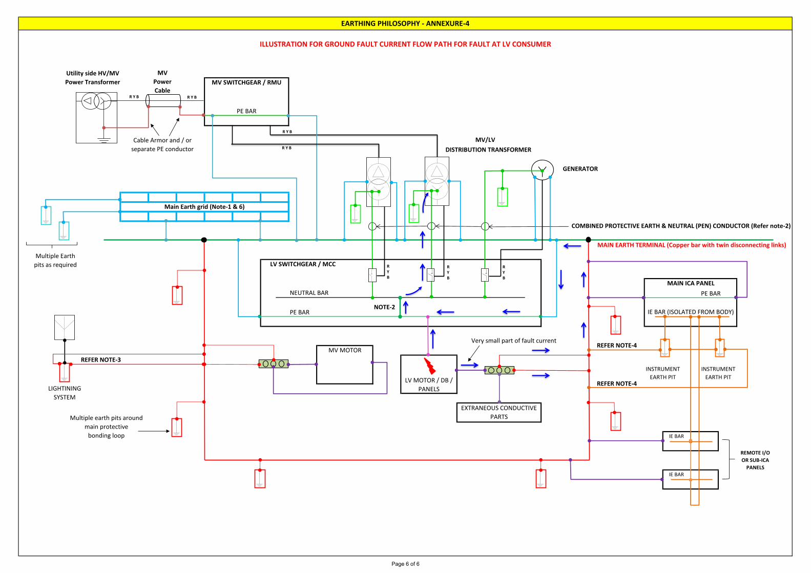
LV system earth fault current is routed back to source transformer neutral through respective protective conductor (PEN / ECC & protective bonding conductor) as illustrated in Annexure-4. As per note-1 above, very negligible earth
fault current flows through general mass of earth and hence not indicated in the diagram.
Earth Continuity Conductor
Ground Potential Rise
Protective Earth & Neutral combined conductor
Earth Fault
LV earth fault current flow path back to source (Refer note-7)
MV earth fault current flow path back to source (Refer note-8)
Instrument earth conductor for ICA system (Y/G PVC insulated copper)
EARTHING PHILOSOPHY
IEC-61000-5-2
Protective conductor (bare copper for buried grid - size as per earthing design calculations & Y/G PVC insulated copper for
grid risers to equipment - size as per Table-C of this document)
Main protective bonding conductor (Y/G PVC insulated copper, size at least half of protective conductor as per clause 544.1
of IEC-60364-5-54)
Protective / supplementary bonding conductor (Y/G PVC insulated copper, size as per Table-A of this document)
ECC - Earth continuity conductor (Y/G PVC insulated copper, size as per Table-54.2 of IEC-60364-5-54, refer Table-B of this
document)
LEGEND:REFERENCE STANDARDS
IEEE-80
IEC-60364-5-54
BS-7430
Earth Dispatcher (Copper bar)
ABBREVIATIONSConcrete inspection earth pit with earth rod (copper, copper bond steel, etc.)
4-pole main incomer breaker (3 phase + PEN)
As per clause 15.8 of IEEE-80, for ground faults on distribution transformer secondary side or LV consumer side, the fault current circulates in the protective conductor (PEN / ECC & partly through protective bonding conductor) with
negligible leakage current into the earth and, thus, has no effect on the Ground Potential Rise (GPR). The transformer's PEN conductor and protective conductor of connected consumers are sized to carry full ground fault current
expected on the circuit and have very low impedance (resistance) compared to earth grid. This is the reason the earth grid is not involved in this fault loop and thus the low-voltage ground fault current is not a sizing parameter for grid.
The main earth grid within the plant needs to be designed only for carrying MV side ground fault current. Utility company, that supplies main power, will provide value of maximum MV ground fault current that it is capable of
supplying. This fault current forms the basis of designing earth grid at distribution substation. Refer note-8 below for further details.
As per Figure-54.1b of IEC-60364-5-54, PEN conductor shall be connected to neutral bar of LV MCC and then further connected with link to its PE bar. The PE bar is connected to earth network through main earth terminal as illustrated
in subsequent annexures. This scheme classifies as TN-C-S earthing scheme with TN-C up to main LV switchgear / MCC and TN-S thereafter on LV distribution side.
Lightning system must be connected to protective bonding loop for equipotential bonding as per Figure-6 of BS-7430 & Annex-B of IEC-60364-5-54
If instrument earthing system is kept isolated from plant earth, in case of lightning or power system ground fault, dangerous transient voltages can occur between isolated instrument earthing system and other parts of the installation
thus compromising personnel safety and EMC. In order to comply with EMC requirement & ensure personal safety, instrument earthing system must be bonded to plant earthing system to have common earthing reference in line with
clause 5.3.1 and figures 5 & 8 of IEC-61000-5-2.
Refer Figure-30 of IEEE-80-2013. MV earth fault current returns back to utility transformer star point; partially through associated incoming utility cable armor and / or separate protective conductor and balance through general earth
mass. Current flowing through earth mass is partly routed through main earth grid and balance through multiple earthed points throughout the plant. Refer Annexures-1 till 3 for illustration of MV ground fault current flow under
various scenarios. Current passing through multiple earthed points will return back to utility transformer star point through general mass of earth without passing through main earth grid. Fault current which flows through main earth
grid is used for sizing the grid and contributes to Ground Potential Rise (GPR) at distribution substation. The part of the current flowing through various earthed points across the plant will cause potential rise at those points & helps
minimizing ground potential difference (across various points of the plant) with respect to main earth grid. The split factor (for current division between main earth grid & other paths) should be referred from Figure-C.1, page-153 of
IEEE-80-2013. This split factor is used in earthing design calculations for designing earth grid. Usually the same is 0.65 (65%).
Since lightning system earth pits & instrument earth pits are finally connected to main earth grid as indicated in subsequent annexures, separate calculations for their earthing resistance are not required since overall earthing
resistance through such connection will be same as main earthing grid.
In case main earth grid requires larger area and is spread around the plant, it will also act as main protective bonding conductor loop within that area and separate bonding conductor loop is not required within that area.
Page 1 of 6

Sr.
1
2
3
4
5
6
7
8
9
10
11
12
13
14
Sr.
1
2
3
4
Annexure-2 Illustration of ground fault current flow path for fault at distribution transformer MV primary side
Annexure-3 Illustration of ground fault current flow path for fault at MV motor
Enclosure of ICA panel
Cable tray / ladder joints and LV cable gland earth tags
MV motor
Enclosure of LV Motors above 55 kW
Skids housing electrical equipment
Steel supports, steel structures, etc.
25
25 (maximum 50)
70
Annexure-4 Illustration of ground fault current flow path for fault at LV consumer
LIST OF ANNEXURES
Annexure-1 Illustration of ground fault current flow path for fault at MV switchgear / RMU
Instrument earth conductor for ICA system 35
Metallic tanks, fence, gate, etc.
6
6
16
MV cable armor / screen earth bond 35
TABLE-B
"S"
Cross sectional area of line
conductor, copper, sq.mm
Minimum cross sectional area of
ECC (Earth Continuity
Conductor), copper, sq.mm
S ≤ 16 S
16 < S ≤ 35 16
S > 35 S / 2
Half of protective conductor
Conductor Size, sq.mm
70
16
25 (maximum 50)
EARTHING PHILOSOPHY
TABLE-A
Main protective bonding loop around the plant
Local Control stations, Junction boxes & Instruments
Enclosure of LV electrical equipment having main power cable size up to & including 35 sq.mm
Enclosure of LV electrical equipment having main power cable size above 35 sq.mm
Enclosure of LV Motors up to & including 55 kW
Y/G PVC insulated copper protective bonding conductor sizes (minimum recommended)
Item Description
16
25
TABLE-C
Transformer body
Generator body
MV switchgear & MV VFD
Enclosure of LV panels connected directly to distribution transformer
Y/G PVC insulated copper earth grid riser conductor sizes
Same as buried grid conductor
Conductor Size, sq.mm
Same as buried grid conductor
Same as buried grid conductor
Same as buried grid conductor
Item Description
Page 2 of 6

DISTRIBUTION TRANSFORMER
GENERATOR
NEUTRAL BAR PE BAR
PE BAR
REMOTE I/O
OR SUB-ICA
PANELSIE BAR
NOTE-2IE BAR (ISOLATED FROM BODY)
REFER NOTE-4
LV MOTOR / DB /
PANELS
INSTRUMENT
EARTH PIT
INSTRUMENT
EARTH PITREFER NOTE-4
REFER NOTE-3
LIGHTINING
SYSTEM
EXTRANEOUS CONDUCTIVE
PARTSMultiple earth pits around
main protective
bonding loop IE BAR
MV MOTOR
Utility side HV/MV
Power Transformer
MV
Power
CableMV SWITCHGEAR / RMU
EARTHING PHILOSOPHY - ANNEXURE-1
MAIN ICA PANEL
PE BAR
Cable Armor and / or
separate PE conductorMV Fault current partial
flow through general
mass of earth
Main Earth grid (Note-1 & 6)
COMBINED PROTECTIVE EARTH & NEUTRAL (PEN) CONDUCTOR (Refer note-2)
Multiple Earth
pits as required
MAIN EARTH TERMINAL (Copper bar with twin disconnecting links)
LV SWITCHGEAR / MCC
ILLUSTRATION FOR GROUND FAULT CURRENT FLOW PATH FOR FAULT AT MV SWITCHGEAR / RMU
MV/LV
RYB
RYB
RYB
R Y B
R Y B
R Y BR Y B
Y
Page 3 of 6

DISTRIBUTION TRANSFORMER
GENERATOR
NEUTRAL BAR PE BAR
PE BAR
REMOTE I/O
OR SUB-ICA
PANELSIE BAR
NOTE-2IE BAR (ISOLATED FROM BODY)
REFER NOTE-4
LV MOTOR / DB /
PANELS
INSTRUMENT
EARTH PIT
INSTRUMENT
EARTH PITREFER NOTE-4
REFER NOTE-3
LIGHTINING
SYSTEM
EXTRANEOUS CONDUCTIVE
PARTSMultiple earth pits around
main protective
bonding loop IE BAR
MV MOTOR
Utility side HV/MV
Power Transformer
MV
Power
CableMV SWITCHGEAR / RMU
EARTHING PHILOSOPHY - ANNEXURE-2
MAIN ICA PANEL
PE BAR
Cable Armor and / or
separate PE conductorMV Fault current partial
flow through general
mass of earth
Main Earth grid (Note-1 & 6)
COMBINED PROTECTIVE EARTH & NEUTRAL (PEN) CONDUCTOR (Refer note-2)
Multiple Earth
pits as required
MAIN EARTH TERMINAL (Copper bar with twin disconnecting links)
LV SWITCHGEAR / MCC
ILLUSTRATION FOR GROUND FAULT CURRENT FLOW PATH FOR FAULT AT DISTRIBUTION TRANSFORMER MV PRIMARY SIDE
MV/LV
RYB
RYB
RYB
R Y B
R Y B
R Y BR Y B
Y
Page 4 of 6

DISTRIBUTION TRANSFORMER
GENERATOR
NEUTRAL BAR PE BAR
PE BAR
REMOTE I/O
OR SUB-ICA
PANELSIE BAR
NOTE-2IE BAR (ISOLATED FROM BODY)
REFER NOTE-4
LV MOTOR / DB /
PANELS
INSTRUMENT
EARTH PIT
INSTRUMENT
EARTH PITREFER NOTE-4
REFER NOTE-3
LIGHTINING
SYSTEM
EXTRANEOUS CONDUCTIVE
PARTSMultiple earth pits around
main protective
bonding loop IE BAR
MV MOTOR
Utility side HV/MV
Power Transformer
MV
Power
CableMV SWITCHGEAR / RMU
EARTHING PHILOSOPHY - ANNEXURE-3
MAIN ICA PANEL
PE BAR
Cable Armor and / or
separate PE conductorMV Fault current partial
flow through general
mass of earth
Main Earth grid (Note-1 & 6)
COMBINED PROTECTIVE EARTH & NEUTRAL (PEN) CONDUCTOR (Refer note-2)
Multiple Earth
pits as required
MAIN EARTH TERMINAL (Copper bar with twin disconnecting links)
LV SWITCHGEAR / MCC
ILLUSTRATION FOR GROUND FAULT CURRENT FLOW PATH FOR FAULT AT MV MOTOR
MV/LV
RYB
RYB
RYB
R Y B
R Y B
R Y BR Y B
Y
Page 5 of 6
DISTRIBUTION TRANSFORMER
GENERATOR
NEUTRAL BAR PE BAR
PE BAR
LIGHTINING
SYSTEM
EXTRANEOUS CONDUCTIVE
PARTSMultiple earth pits around
main protective
bonding loop IE BAR
MV MOTOR
REFER NOTE-3
REMOTE I/O
OR SUB-ICA
PANELSIE BAR
MAIN ICA PANEL
NOTE-2IE BAR (ISOLATED FROM BODY)
REFER NOTE-4
LV MOTOR / DB /
PANELS
INSTRUMENT
EARTH PIT
INSTRUMENT
EARTH PITREFER NOTE-4
Very small part of fault current
Main Earth grid (Note-1 & 6)
COMBINED PROTECTIVE EARTH & NEUTRAL (PEN) CONDUCTOR (Refer note-2)
Multiple Earth
pits as required
MAIN EARTH TERMINAL (Copper bar with twin disconnecting links)
LV SWITCHGEAR / MCC
PE BAR
MV/LV
EARTHING PHILOSOPHY - ANNEXURE-4
ILLUSTRATION FOR GROUND FAULT CURRENT FLOW PATH FOR FAULT AT LV CONSUMER
Utility side HV/MV
Power Transformer
MV
Power
CableMV SWITCHGEAR / RMU
Cable Armor and / or
separate PE conductor
RYB
RYB
RYB
R Y B
R Y B
R Y BR Y B
Y
Page 6 of 6