easergy range l500 v4 - rza.byvalidation of your master plan without the establishment of a dms type...
TRANSCRIPT

MV electrical network management Easergy range
L500 V4.2 MV substation supervision system
Technical leaflet
L500 technical data Introduction
2 ENMED309019EN
Easergy L500 is a basic SCADA system running under Windows XP Professional SP2 or SP3, Windows Server 2003 Standard and Enterprise Editions, Windows Server 2003 Release 2 Standard and Enterprise Editions, designed to monitor, in a few clicks, the products of the Schneider Electric Telecontrol Easergy range and of the Schneider Recloser Solutions ADVC range with ACR function (series U and series N).
Its relevant functions and its quality/price ratio make it an exceptional tool for the following applications: � Remote control of small networks. � Provisional system pending the implementation of a DMS. � Maintenance of the installed base. � Experimenting. Easergy L500 assures you of: � An immediate return on capital through operation of your network as of the
initial investment in substations. � Validation of your Master Plan without the establishment of a DMS type remote
control system. � Balanced and gradual learning by the personnel in charge of network
operation. With the guarantee of compatibility of the Easergy range (T200, F200C and G200) and of the ADVC range with ACR function (series U and N) with any type of SCADA DMS proven by our projects, we offer you a comprehensive solution for the initial phases of your project while capitalizing on the investment made in substations.
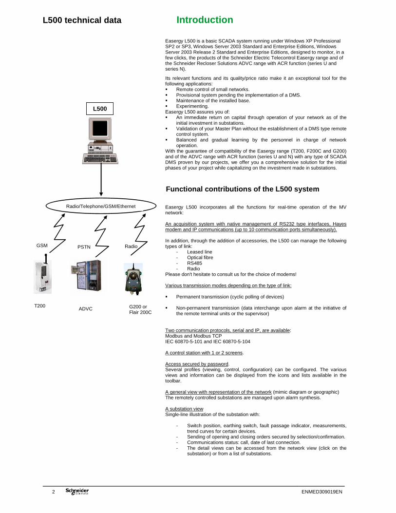
Functional contributions of the L500 system Easergy L500 incorporates all the functions for real-time operation of the MV network: An acquisition system with native management of RS232 type interfaces, Hayes modem and IP communications (up to 10 communication ports simultaneously). In addition, through the addition of accessories, the L500 can manage the following types of link:
- Leased line - Optical fibre - RS485 - Radio
Please don't hesitate to consult us for the choice of modems! Various transmission modes depending on the type of link: � Permanent transmission (cyclic polling of devices)
� Non-permanent transmission (data interchange upon alarm at the initiative of
the remote terminal units or the supervisor) Two communication protocols, serial and IP, are available: Modbus and Modbus TCP IEC 60870-5-101 and IEC 60870-5-104 A control station with 1 or 2 screens. Access secured by password. Several profiles (viewing, control, configuration) can be configured. The various views and information can be displayed from the icons and lists available in the toolbar. A general view with representation of the network (mimic diagram or geographic) The remotely controlled substations are managed upon alarm synthesis. A substation view Single-line illustration of the substation with:
- Switch position, earthing switch, fault passage indicator, measurements,
trend curves for certain devices. - Sending of opening and closing orders secured by selection/confirmation. - Communications status: call, date of last connection. - The detail views can be accessed from the network view (click on the
substation) or from a list of substations.
GSM
Radio/Telephone/GSM/Ethernet
PSTN Radio
L500
T200 G200 or Flair 200C
ADVC

L500 technical data Introduction
ENMED309019EN 3
Alarm views Refreshed in real time. - The last 6 alarms are displayed on all the views. - An overall alarm view. Can be consulted by substation and by filter. They are animated by colours according to their status. An archive log Can be consulted by substation and by filter. The archive logs are archived in a proprietary database or in an SQL database. A system view With status of communication equipment. Multistation architectures Allowing network management by several operator stations. Web access (1 or 2 simultaneous accesses) for standby duty station or mobile station. Please don't hesitate to consult us for more than 2 simultaneous Web accesses! A business area configurator for the creation of remotely controlled substations and transmissions in a few clicks. � The applications can be constantly enhanced by this editor. � The illustrations of network and substation views can be enhanced by the
supervisor's graphics editor. Complementary system functions � Remote terminal unit time setting by the protocol. � Call management: general check, automatically and at the operator's request,
regular call, one-off call on request. � Event log printer management. Numerous accessories come with the Easergy L500 offering. � Easergy G500 FSK or FFSK radio modem; � PSTN and GSM modem; � FSK 4-wire leased line modem; � RS232/optical fibre interface; � External luminous and audible alarm.
Basic principles of the L500 system The L500 is based on a basic system with a range of options described in full in this document. The basic system provides all the functions necessary for network management. It is included in all L500 projects. The options allow extension of the system to make it more efficient and profitable. The options are included in the project only if they are explicitly mentioned in the tender documents. To summarize, the system comprises the following components:
� An operator interface; � Basic control and surveillance functions (SCADA); � Archiving tools; � Communication tools; � System configuration tools (L500 configurator).

L500 technical data Operator interface
4 ENMED309019EN
To succeed in a market in which competition is increasingly fierce, electricity utilities must monitor their networks in a new way. These companies must have ergonomic systems enabling them to optimize management of their electrical network while increasing continuity of service for their customers. The operator interface is a key component of the system. The operators must be capable of taking action on the network easily and rapidly, in safe and efficient conditions, especially in the event of a fault on the network. The interface of the L500 system has been designed taking these factors into account. The operator interface is a human-machine interface (HMI) which allows users to interact with the system in the most efficient and ergonomic manner possible. Three operating modes are available at the system level. The HMI covers each mode:
- Network monitoring enables the operator to manage the electrical network in the safest and most efficient conditions;
- System configuration enables the operator to create and update the electrical network diagram in the most efficient manner;
- System administration enables the system administrator to configure the system (user access, screen layout, etc.).
These various operating modes have controlled accessibility thanks to the use of operator rights mechanisms. The HMI of the L500 system is available for several language combinations:
- French/English - Russian/English(*) - Chinese/English(*)
(*): The devices available in Russian and Chinese are the T200 and the Flair200C series 3. Options are available to increase both the number of screens per operator station (maximum of 2 screens) and the total number of operator stations. The possible number of operator stations depends of course on the size of the application. When an operator station comprises several screens, no special interaction with the keyboard is needed to move the mouse from one screen to another. The operator stations are standardized. The three system modes can be used on any operator station. Each electricity distributor can of course define operator profiles for specific modes (e.g. certain types of operator profile for controlling the network and other types for network supervision). Depending on the number of screens chosen and the ergonomics he wants, the system administrator can alter the size and layout of the various output windows (e.g., window(s) for the network diagram, alarm list). The image of a substation can be accessed by clicking on the graphic representation of the substation. Each symbol can be a passive graphic representation of a network component, or can contain dynamic graphic elements. For example, an element representing a switch can be updated (in real time) to illustrate opening or closing of the switch. This updating always includes a change of shape. Control operations can be performed on the diagram symbols by means of the mouse and without using the keyboard:
- Display of detailed network zones; - Remote control of a device to change its position; - Display of a change in an analogue measurement.
Network view
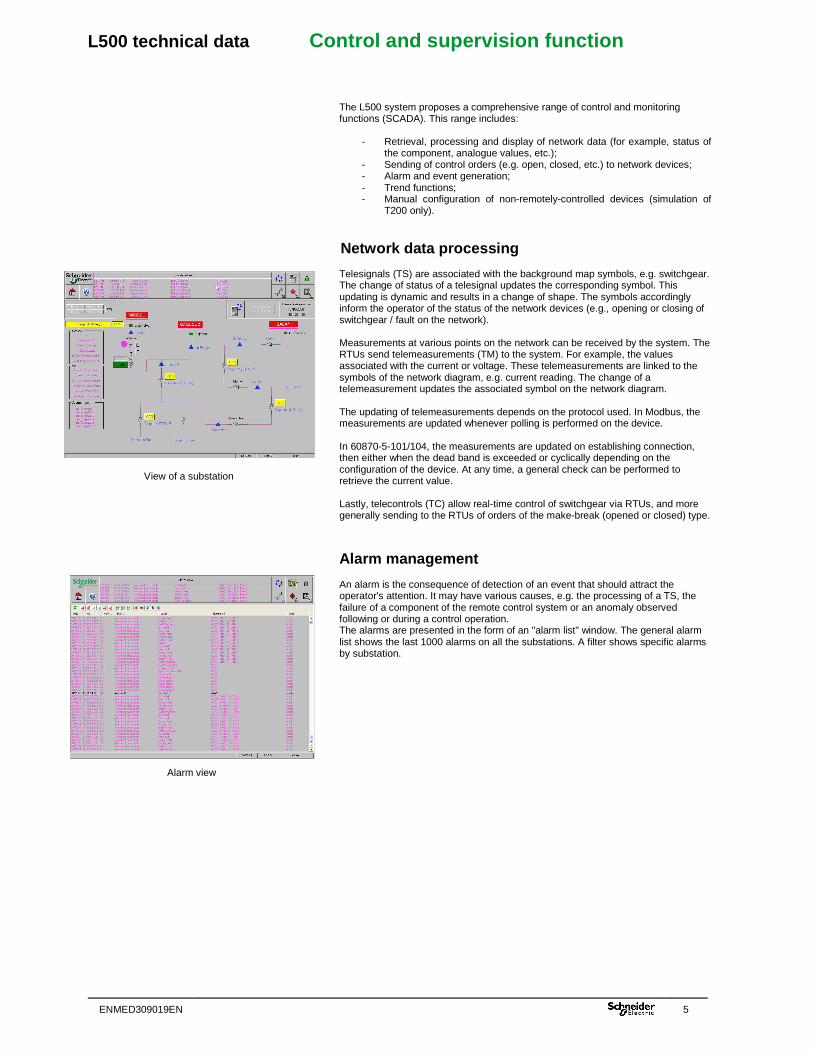
View of a substation
L500 technical data Control and supervision function
ENMED309019EN 5
The L500 system proposes a comprehensive range of control and monitoring functions (SCADA). This range includes:
- Retrieval, processing and display of network data (for example, status of the component, analogue values, etc.);
- Sending of control orders (e.g. open, closed, etc.) to network devices; - Alarm and event generation; - Trend functions; - Manual configuration of non-remotely-controlled devices (simulation of
T200 only).
Network data processing
Telesignals (TS) are associated with the background map symbols, e.g. switchgear. The change of status of a telesignal updates the corresponding symbol. This updating is dynamic and results in a change of shape. The symbols accordingly inform the operator of the status of the network devices (e.g., opening or closing of switchgear / fault on the network).
Measurements at various points on the network can be received by the system. The RTUs send telemeasurements (TM) to the system. For example, the values associated with the current or voltage. These telemeasurements are linked to the symbols of the network diagram, e.g. current reading. The change of a telemeasurement updates the associated symbol on the network diagram. The updating of telemeasurements depends on the protocol used. In Modbus, the measurements are updated whenever polling is performed on the device. In 60870-5-101/104, the measurements are updated on establishing connection, then either when the dead band is exceeded or cyclically depending on the configuration of the device. At any time, a general check can be performed to retrieve the current value.
Lastly, telecontrols (TC) allow real-time control of switchgear via RTUs, and more generally sending to the RTUs of orders of the make-break (opened or closed) type.
Alarm management An alarm is the consequence of detection of an event that should attract the operator's attention. It may have various causes, e.g. the processing of a TS, the failure of a component of the remote control system or an anomaly observed following or during a control operation. The alarms are presented in the form of an "alarm list" window. The general alarm list shows the last 1000 alarms on all the substations. A filter shows specific alarms by substation.
View of a substation
Alarm view

L500 technical data Control and supervision function
6 ENMED309019EN
Updating of the system database Consistency of the system data with the RTU data is ensured by the repatriation of telesignals from the RTU. This repatriation is called a "general check" (GC). Requests for a general check on a RTU can be made at the initiative of the operator or automatically by a cyclic call. Moreover, during a call issued by the RTU (case of an alarm), the remote control system repatriates the entire database from the RTU.
System synchronization The system synchronizes the RTUs via the protocol. Time stamping of events and alarms is managed at source by the RTUs.
L500 technical data Archiving
ENMED309019EN 7
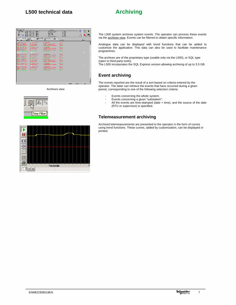
The L500 system archives system events. The operator can process these events via the archives view. Events can be filtered to obtain specific information. Analogue data can be displayed with trend functions that can be added to customize the application. This data can also be used to facilitate maintenance programmes. The archives are of the proprietary type (usable only via the L500), or SQL type (open to third-party tools). The L500 incorporates the SQL Express version allowing archiving of up to 3.5 GB.
Event archiving The events reported are the result of a sort based on criteria entered by the operator. The latter can retrieve the events that have occurred during a given period, corresponding to one of the following selection criteria:
- Events concerning the whole system; - Events concerning a given "substation"; - All the events are time-stamped (date + time), and the source of the date
(RTU or supervisor) is specified.
Telemeasurement archiving Archived telemeasurements are presented to the operator in the form of curves using trend functions. These curves, added by customization, can be displayed or printed.
Archives view
L500 technical data Communication functions
8 ENMED309019EN
To facilitate the SCADA functions and the associated advanced functions, the L500 system is designed for easy interfacing with Schneider Electric RTUs: Easergy range and ADVC range with ACR function (N and U series).
Communication with remote terminal units (RTUs) The communication functions are responsible for correct message routing between the remote control functions and the remote terminal units (RTUs). In particular, they provide end-to-end control of transmission and manage data transmission network access. The communication functions allow supervision of connection status, fault finding and local logging of communication-related events. The system manages up to 10 networks and several protocols simultaneously. The system is capable of managing the following protocols:
- IEC 870-5-101 and Modbus RTU for so-called ‘serial' networks. The Modbus and IEC 870-5-101 protocols of the L500 support time stamping of events.
- IEC 870-5-104 and Modbus TCP for so-called ‘IP’ networks. The Modbus TCP and IEC 870-5-104 protocols of the L500 support time stamping of events. The L500 can manage a variable number of devices depending on the communication medium and the number of variables. Please don't hesitate to consult us!
Communication networks The L500 can communicate with RTUs on the following networks: GSM / PSTN / GPRS / Ethernet. It can also communicate with LL, RS485 and Radio networks by adding RS232 converters to the type of link to be managed. Special attention has been paid to IP networks (Ethernet and GPRS). In Modbus TCP protocol, the L500 manages the following access modes:
- Permanent: for Ethernet and high-speed networks. The L500 performs Master/Slave type polling in this mode. Refreshment of variables on screen is instantaneous.
- Semi-permanent: for GPRS networks. Communication is of the Master/Master type. Data interchange between devices takes place: upon alarm/upon routine general check and at the user's request. Since invoicing on GPRS networks is based on the volume of data exchanged, this mode offers the user an economical means of communication for this type of network.
- Non-permanent: for devices with low power supply (e.g. solar panel power supply of the G200).
With the IEC 870-5-104 protocol, the L500 manages semi-permanent access. GPRS communications between devices require the use of a private APN to: - Secure exchanges with the devices; - Have static IP addresses on the devices; - Be protected from undesirable flows for solar devices; This access mode is provided by the telephone operator. Please don't hesitate to consult us for further information.
L500 technical data Communication functions
ENMED309019EN 9
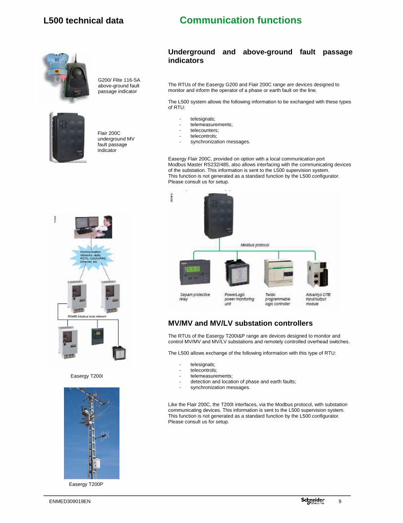
Underground and above-ground fault passage indicators The RTUs of the Easergy G200 and Flair 200C range are devices designed to monitor and inform the operator of a phase or earth fault on the line. The L500 system allows the following information to be exchanged with these types of RTU:
- telesignals; - telemeasurements; - telecounters; - telecontrols; - synchronization messages.
Easergy Flair 200C, provided on option with a local communication port Modbus Master RS232/485, also allows interfacing with the communicating devices of the substation. This information is sent to the L500 supervision system. This function is not generated as a standard function by the L500 configurator. Please consult us for setup.
MV/MV and MV/LV substation controllers The RTUs of the Easergy T200I&P range are devices designed to monitor and control MV/MV and MV/LV substations and remotely controlled overhead switches. The L500 allows exchange of the following information with this type of RTU:
- telesignals; - telecontrols; - telemeasurements; - detection and location of phase and earth faults; - synchronization messages.
Like the Flair 200C, the T200I interfaces, via the Modbus protocol, with substation communicating devices. This information is sent to the L500 supervision system. This function is not generated as a standard function by the L500 configurator. Please consult us for setup.
G200/ Flite 116-SA above-ground fault passage indicator
Flair 200C underground MV fault passage indicator
Easergy T200I
Easergy T200P
L500 technical data Communication functions
10 ENMED309019EN
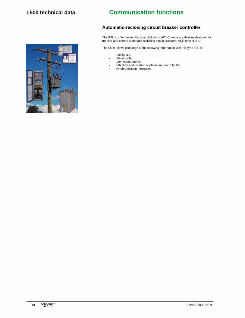
Automatic-reclosing circuit breaker controller The RTUs of Schneider Recloser Solutions' ADVC range are devices designed to monitor and control automatic-reclosing circuit breakers: ACR type N or U. The L500 allows exchange of the following information with this type of RTU:
- telesignals; - telecontrols; - telemeasurements; - detection and location of phase and earth faults; - synchronization messages.
L500 technical data System configuration tools
ENMED309019EN 11
In modern remote control systems, it is essential for the user to have the most efficient and profitable maintenance and configuration functions possible.
For this reason, these functions must be available via a sophisticated graphic interface allowing optimized control of the electrical network.
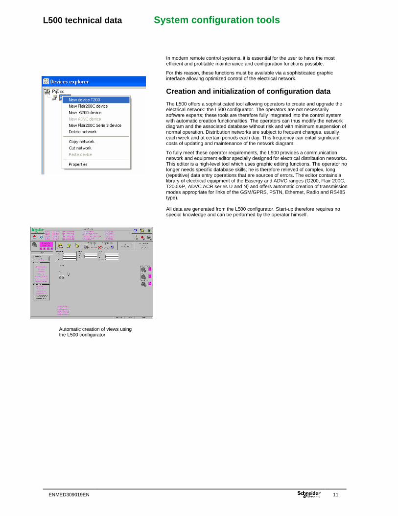
Creation and initialization of configuration data The L500 offers a sophisticated tool allowing operators to create and upgrade the electrical network: the L500 configurator. The operators are not necessarily software experts; these tools are therefore fully integrated into the control system with automatic creation functionalities. The operators can thus modify the network diagram and the associated database without risk and with minimum suspension of normal operation. Distribution networks are subject to frequent changes, usually each week and at certain periods each day. This frequency can entail significant costs of updating and maintenance of the network diagram.
To fully meet these operator requirements, the L500 provides a communication network and equipment editor specially designed for electrical distribution networks. This editor is a high-level tool which uses graphic editing functions. The operator no longer needs specific database skills; he is therefore relieved of complex, long (repetitive) data entry operations that are sources of errors. The editor contains a library of electrical equipment of the Easergy and ADVC ranges (G200, Flair 200C, T200I&P, ADVC ACR series U and N) and offers automatic creation of transmission modes appropriate for links of the GSM/GPRS, PSTN, Ethernet, Radio and RS485 type). All data are generated from the L500 configurator. Start-up therefore requires no special knowledge and can be performed by the operator himself.
Automatic creation of views using the L500 configurator
L500 technical data System architecture
12 ENMED309019EN
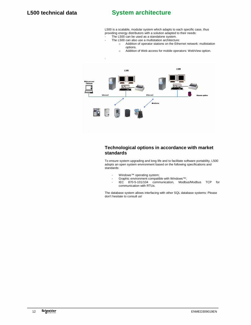
L500 is a scalable, modular system which adapts to each specific case, thus providing energy distributors with a solution adapted to their needs: - The L500 can be used as a standalone system. - The L500 can also use a multistation architecture:
o Addition of operator stations on the Ethernet network: multistation options.
o Addition of Web access for mobile operators: WebView option. .
Technological options in accordance with market standards To ensure system upgrading and long life and to facilitate software portability, L500 adopts an open system environment based on the following specifications and standards:
- Windows™ operating system; - Graphic environment compatible with Windows™; - IEC 870-5-101/104 communication, Modbus/Modbus TCP for
communication with RTUs. The database system allows interfacing with other SQL database systems: Please don't hesitate to consult us!

L500 technical data Characteristics and accessories
ENMED309019EN 13
Characteristics Operating system Windows XP Service Pack 2 or higher
Windows 2003 Server Communication networks RS232, PSTN and IP link (Ethernet, GPRS)
with native management. Leased line, optical fibre, RS485, Radio via converter or accessories.
Communication ports Up to 10 COM RS232 or Hayes Communication protocols Modbus RTU / Modbus TCP
IEC 870-5-101 / IEC 870-5-104 Maximum number of devices Depends on the type of medium and the
number of variables. Please consult us.
Number of variables available 256 / 1000 / 5000 / 65000
Type of architecture Standalone Multistation: 1 server / n clients (n depending on the size of the application) Requires the purchase of a "Full Version" key and n "Client station" keys Web access: Up to 2 users simultaneously, above that please consult us. Requires the purchase of a "Full Version + WebView" key ref.: L500-FWBV1-X-1 (1 user) or L500-FWBV21-X-1 (2 users)
Accessories Horn option allowing visual indication of the presence of a fault ref. L500-ext-alarms GSM Gener modem ref. MODEM-GSM+KIT-GSM
Easergy G500 modem with FSK radio modem ref. G500M-M-B
Easergy G500 modem with FFSK radio modem ref. G500M-M-C
USB PSTN modem ref. Olitec-PSTN-USB
Easergy G500 modem with RS232 interface (please consult us)
FSK 1200 baud LL modem, Black box ref. MDU910LL
RS232 optic insulator, Black box ref. RS232-OPTI-ISO
L500 technical data System updating and maintenance
14 ENMED309019EN
Schneider applies a policy of continual improvement of its products and its services. Each L500 system is implemented with the most recent available version of the system. System updating and maintenance can take several forms:
- Hardware extension of the system; - Extension of system functionalities; - Upgrading of the system software to a new version.
In view of changing customer needs, Schneider Electric proposes a maintenance and service policy based on contracts and services adapted to each case. Please don't hesitate to contact your dealer for more information.

L500 technical data Personal notes
ENMED309019EN 15

16 ENMED309019EN
Schneider Electric Industries SAS 35,rue Joseph Monier CS 30323 F - 92506 Rueil Malmaison Cedex RCS Nanterre 954 503 439 Capital social 896 313 776 € www.schneider-electric.com
En raison de l’évolution des normes et du matériel, les caractéristiques indiquées par les textes et les images de ce document ne nous engagent qu’après confirmation par nos services. Publication : Schneider Electric Industries SAS Réalisation : Schneider Electric Industries SAS
ENMED309019EN 06/2009 Publishing, layout and printing: Schneider Electric Telecontrol Made in France - Europe