east african community - eac quality
TRANSCRIPT

CD/K/57/2004 ICS 91.060.10; 91.060.20
© EAS 2004 First Edition 2004
DRAFT EAST AFRICAN STANDARD
Code of practice for Galvanized and aluminium zinc corrugated steel Sheet roofing and wall covering
EAST AFRICAN COMMUNITY
CD/K/57/2004
ii © EAS 2004 — All rights reserved
Table of contents 1 Scope ............................................................................................................................................. 1 2 Normative references ..................................................................................................................... 1 3 Definitions ....................................................................................................................................... 1 4 Exchange of information and time schedule .................................................................................. 1 5 Materials, appliances and components ........................................................................................ 12
5.1 Galvanized corrugated steel sheets ...................................................................................... 2 5.2 Profiles and dimensions of galvanized corrugated steel sheets ............................................ 2 5.3 Accessories and fittings ......................................................................................................... 2 5.4 Fixing accessories ................................................................................................................. 2 5.5 Sealing material ..................................................................................................................... 2 5.7 Galvanized rainwater goods .................................................................................................. 2 5.8 Walkways ............................................................................................................................. 23
6 Design considerations .................................................................................................................... 3 6.1 General .................................................................................................................................. 3 6.2 Durability ................................................................................................................................ 3 6.3 Weathertightness ................................................................................................................... 3 6.4 Thermal insulation ................................................................................................................. 4 6.5 Fire hazard ............................................................................................................................. 4 6.6 Condensation ......................................................................................................................... 4 6.7 Weight of sheeting ................................................................................................................. 4 6.8 Purlin spacing and strength of sheeting ................................................................................ 4 6.9 Methods of fixing the sheeting ............................................................................................... 6 6.10 Pipes, etc., passing through roofing ...................................................................................... 6 6.11 Roof ventilators and roof lights .............................................................................................. 7 6.12 Gutters and rainwater pipes................................................................................................... 7 6.13 Walkways and roof-boards .................................................................................................... 9
7 Application ...................................................................................................................................... 9 7.1 Safety precautions ................................................................................................................. 9 7.2 Ladders, scaffolding and hoists ............................................................................................. 9 7.3 Storage and handling of sheets at suppliers stores or on site ............................................... 9 7.4 Preparation of sheet for roofing and vertical cladding ......................................................... 10 7.5 Layout of the sheeting ......................................................................................................... 10 7.6 Fixing the sheets .................................................................................................................. 10 7.7 Fixing of accessories ....................................................................................................... 1011
8 Inspection on site.......................................................................................................................... 11 9 Maintenance ................................................................................................................................. 11
9.1 General ................................................................................................................................ 11 9.2 Need for painting ................................................................................................................. 11 9.3 Paints suitable for galvanized sheets .............................................................................. 1112
Annex A Thermal transmittance (U value) .......................................................................................... 13
CD/K/47-1/2004
© EAS 2003 — All rights reserved iii
Foreword Development of the East African Standards has been necessitated by the need for harmonizing requirements governing quality of products and services in East Africa. It is envisaged that through harmonized standardization, trade barriers which are encountered when goods and services are exchanged within the Community will be removed. In order to meet the above objectives, the EAC Partner States have enacted an East African Standardization, Quality Assurance, Metrology and Test Act, 2006 (EAC SQMT Act, 2006) to make provisions for ensuring standardization, quality assurance, metrology and testing of products produced or originating in a third country and traded in the Community in order to facilitate industrial development and trade as well as helping to protect the health and safety of society and the environment in the Community. East African Standards are formulated in accordance with the procedures established by the East African Standards Committee. The East African Standards Committee is established under the provisions of Article 4 of the EAC SQMT Act, 2006. The Committee is composed of representatives of the National Standards Bodies in Partner States, together with the representatives from the private sectors and consumer organizations. Draft East African Standards are circulated to stakeholders through the National Standards Bodies in the Partner States. The comments received are discussed and incorporated before finalization of standards, in accordance with the procedures of the Community. Article 15(1) of the EAC SQMT Act, 2006 provides that “Within six months of the declaration of an East African Standard, the Partner States shall adopt, without deviation from the approved text of the standard, the East African Standard as a national standard and withdraw any existing national standard with similar scope and purpose”.
East African Standards are subject to review, to keep pace with technological advances. Users of the East African Standards are therefore expected to ensure that they always have the latest versions of the standards they are implementing.
© East African Community 2008 — All rights reserved*
East African Community
P O Box 1096
Arusha
Tanzania
Tel: 255 27 2504253/8
Fax: 255-27-2504481/2504255
E-Mail: [email protected]
Web: www.each.int
[Based on BS CP 143-10:1973]
* 2008 EAC — All rights of exploitation in any form and by any means reserved worldwide for EAC Partner States’ NSBs.

CD/K/57/2004
© EAS 2004 — All rights reserved 1
Code of practice for Galvanized and aluminium zinc corrugated steel Sheet roofing and wall covering
1 Scope This code of practice deals with the use of galvanized and 55% aluminum zinc corrugated steel sheets for roofing and cladding in building Recommendations are given on materials and design, construction and maintenance, together with information on weather-tightness, durability, thermal insulation, fire hazard, rainwater drainage from roofs and other characteristics.
2 Normative references The following referenced documents are indispensable for the application of this East African Standard. For dated references, only the edition cited applies. For undated references, the latest edition of the referenced document (including any amendments) applies. ISO 559:1991, Steel tubes for water and sewage ISO 6594:2006, Cast iron drainage pipes and fittings — Spigot series EAS 410 EAS 416:2005, Building and civil engineering terms — Parts of construction works — Roofs and roofing ISO 8992:2005, Fasteners — General requirements for bolts, screws, studs and nuts ISO 3506-1:1997, Mechanical properties of corrosion-resistant stainless steel fasteners — Part 1: Bolts, screws and studs ISO 3506-2:1997, Mechanical properties of corrosion-resistant stainless-steel fasteners — Part 2: Nuts ISO 898-1:1999, Mechanical properties of fasteners made of carbon steel and alloy steel — Part 1: Bolts, screws and studs ISO 3575:2005, Continuous hot-dip zinc-coated carbon steel sheet of commercial and drawing qualities EAS 11:2008, Galvanized plain and corrugated iron sheets — Specification ISO 16813:2006, Building environment design — Indoor environment — General principles ISO 4354:1997, Wind actions on structures
3 Definitions For the purposes of this East African Standard, the definitions of roof and wall cladding terms given in EAS 416 apply.
4 Exchange of information and time schedule The working drawings and specification should be prepared in sufficient detail to afford proper guidance in the preparation of estimates and the execution of the work. There should be a full exchange of information between all concerned with the roofing and the work adjacent to it in sufficient time to ensure that the covering can be carried out at the proper time and that all necessary provisions for fixing have been made in advance. Early arrangements should be made on the site for rainwater disposal. Roof covering should be completed before internal finishes are begun.
5 Materials, appliances and components
EAST AFRICAN STANDARD
2 © EAS 2004 — All rights reserved
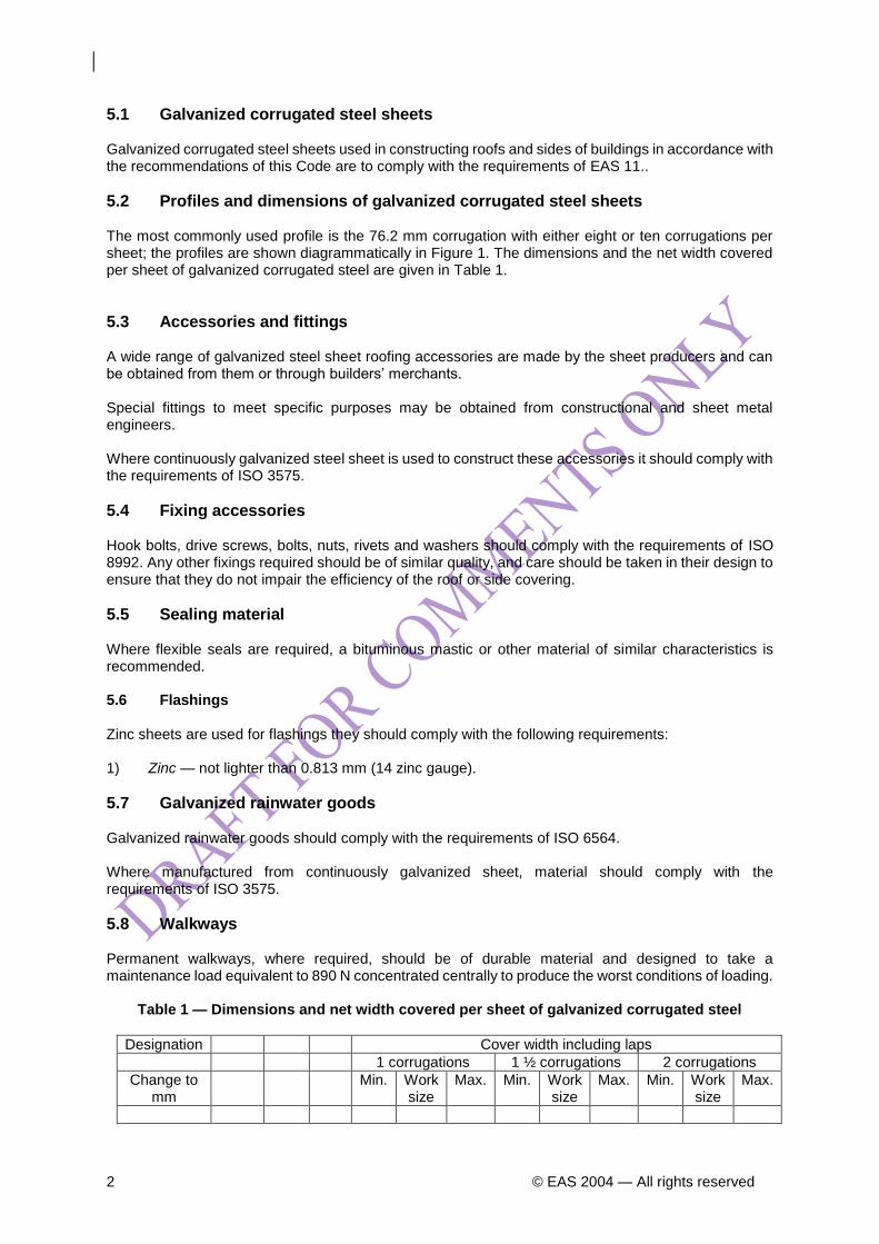
5.1 Galvanized corrugated steel sheets Galvanized corrugated steel sheets used in constructing roofs and sides of buildings in accordance with the recommendations of this Code are to comply with the requirements of EAS 11..
5.2 Profiles and dimensions of galvanized corrugated steel sheets The most commonly used profile is the 76.2 mm corrugation with either eight or ten corrugations per sheet; the profiles are shown diagrammatically in Figure 1. The dimensions and the net width covered per sheet of galvanized corrugated steel are given in Table 1.
5.3 Accessories and fittings A wide range of galvanized steel sheet roofing accessories are made by the sheet producers and can be obtained from them or through builders’ merchants. Special fittings to meet specific purposes may be obtained from constructional and sheet metal engineers. Where continuously galvanized steel sheet is used to construct these accessories it should comply with the requirements of ISO 3575.
5.4 Fixing accessories Hook bolts, drive screws, bolts, nuts, rivets and washers should comply with the requirements of ISO 8992. Any other fixings required should be of similar quality, and care should be taken in their design to ensure that they do not impair the efficiency of the roof or side covering.
5.5 Sealing material Where flexible seals are required, a bituminous mastic or other material of similar characteristics is recommended. 5.6 Flashings Zinc sheets are used for flashings they should comply with the following requirements: 1) Zinc — not lighter than 0.813 mm (14 zinc gauge).
5.7 Galvanized rainwater goods Galvanized rainwater goods should comply with the requirements of ISO 6564. Where manufactured from continuously galvanized sheet, material should comply with the requirements of ISO 3575.
5.8 Walkways Permanent walkways, where required, should be of durable material and designed to take a maintenance load equivalent to 890 N concentrated centrally to produce the worst conditions of loading.
Table 1 — Dimensions and net width covered per sheet of galvanized corrugated steel
Designation Cover width including laps
1 corrugations 1 ½ corrugations 2 corrugations
Change to mm
Min. Work size
Max. Min. Work size
Max. Min. Work size
Max.
CD/K/57/2004
© EAS 2004 — All rights reserved 3
8/3 in mm
660.4
mm
76.2
mm
19
mm
605
mm
610
mm
615
mm
567
mm
572
mm
577
mm
528
mm
533
mm
538
10/3 n 812.8 76.2 19 757 762 767 719 724 729 681 686 691
12/3 in 966.2 76.2 19 908 914 920 870 876 882 832 838 844
5/5 in 711.2 127 32 630 635 640 — — — — — —
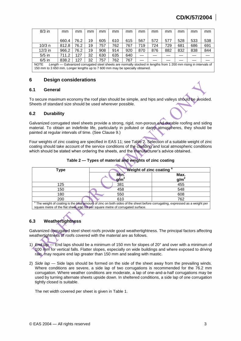
6/5 in 838.2 127 32 757 762 767 — — — — — — NOTE Length — Galvanized corrugated steel sheets are normally stocked in lengths from 1 200 mm rising in intervals of 150 mm to 3 650 mm. Longer lengths up to 7 600 mm may be specially obtained.
6 Design considerations
6.1 General To secure maximum economy the roof plan should be simple, and hips and valleys should be avoided. Sheets of standard size should be used wherever possible.
6.2 Durability Galvanized corrugated steel sheets provide a strong, rigid, non-porous and durable roofing and siding material. To obtain an indefinite life, particularly in polluted or damp atmospheres, they should be painted at regular intervals of time. (See Clause 9.) Four weights of zinc coating are specified in EAS 11; see Table 2. Selection of a suitable weight of zinc coating should take account of the service conditions of the cladding and local atmospheric conditions which should be stated when ordering the sheets, and the manufacturer’s advice obtained.
Table 2 — Types of material and weights of zinc coating
Type Weight of zinc coating a
Min. Max.
g/m2
g/m2
125 381 455
150 458 548
180 550 608
200 610 762 a The weight of coating is the total amount of zinc on both sides of the sheet before corrugating, expressed as a weight per
square metre of the flat sheet and not per square metre of corrugated surface.
6.3 Weathertightness Galvanized corrugated steel sheet roofs provide good weathertightness. The principal factors affecting weathertightness of roofs covered with the material are as follows. 1) End lap — End laps should be a minimum of 150 mm for slopes of 20° and over with a minimum of
100 mm for vertical falls. Flatter slopes, especially on wide buildings and where exposed to driving rain, may require end lap greater than 150 mm and sealing with mastic.
2) Side lap — Side laps should be formed on the side of the sheet away from the prevailing winds.
Where conditions are severe, a side lap of two corrugations is recommended for the 76.2 mm corrugation. Where weather conditions are moderate, a lap of one-and-a-half corrugations may be used by turning alternate sheets upside down. In sheltered conditions, a side lap of one corrugation tightly closed is suitable.
The net width covered per sheet is given in Table 1.
4 © EAS 2004 — All rights reserved
3) Accessories — Whenever possible, accessories should be chosen from stock patterns; special fittings, if required, should be designed to fit closely. Accessories should be carefully fitted to make a weathertight joint.
4) Rainwater discharging on the roof — No gutter or rainwater pipe should be allowed to discharge on
to the roofing.
6.4 Thermal insulation Galvanized corrugated steel sheeted roots can be insulated thermally to suit all requirements. The thermal transmittance can be adjusted to any required value by the use of insulating material laid either between the purlins and the sheeting or under the purlins, thus incorporating an air gap. For information regarding heat losses through roofs see Annex A.
6.5 Fire hazard Galvanized corrugated steel roofing sheets are non-combustible and would make no contribution to a fire. Structures incorporating galvanized corrugated steel sheet may be designed to give any desired fire resistance when combined with suitable materials.
6.6 Condensation Condensation may occur under certain weather conditions but may be avoided by ensuring adequate ventilation of the under side of the roof. This may be effected by laying the sheets with a gap between them made weathertight by increasing the overlaps or by employing specially louvred sheets. When the roof is lined with thermal insulation board, the possibility of interstitial condensation should not be overlooked and it is generally advisable to provide a water vapour barrier at the surface facing the interior of the building. This can be an impervious membrane or a sprayed “cocoon”. The additional precaution of providing ventilation through the sheets will also reduce condensation and will not greatly reduce the thermal insulation of the lining. The application of special surface treatments, such as anticondensation paint, may, under certain conditions, also be effective in reducing condensation.
6.7 Weight of sheeting The approximate weight of galvanized sheeting as fixed, including side and end laps, is given in Table 3.
6.8 Purlin spacing and strength of sheeting The purlin spacing for roofs covered with galvanized corrugated steel sheets should preferably be arranged with a view to using standard sheets of uniform length throughout. Ridge purlins should be as near to the ridge as possible, having regard to the type of ridge capping to be used and the manner in which it is to be fixed. If ventilators are to be situated along the ridge, care should be taken that the ridge purlins do not obstruct the passage of air. A roof will have to withstand wind loads as well as any concentrated loads that may arise during maintenance in accordance with ISO 4354 and ISO 2103.
Table 3 — Approximate weight of sheeting for 76.2 mm and 127 mm corrugations per square metre as fixed (including side and end laps)
Gauge Weight
N/m2
16 180
17 165
18 145
CD/K/57/2004
© EAS 2004 — All rights reserved 5
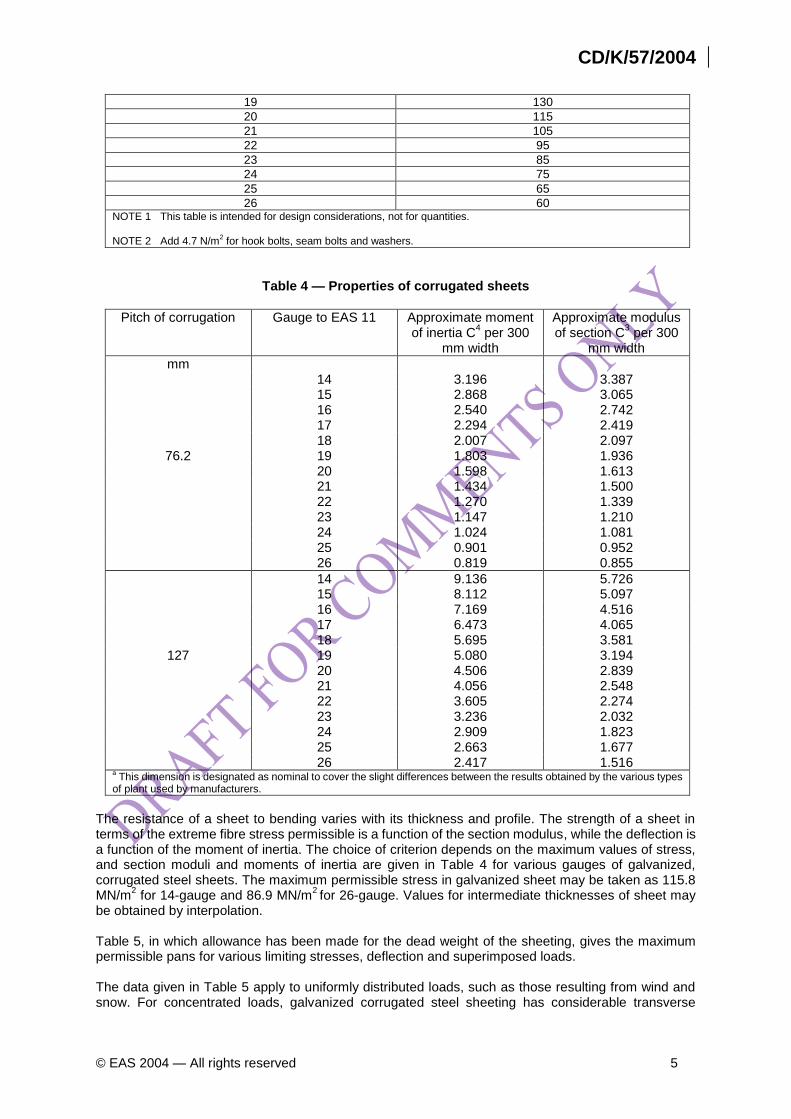
19 130
20 115
21 105
22 95
23 85
24 75
25 65
26 60 NOTE 1 This table is intended for design considerations, not for quantities. NOTE 2 Add 4.7 N/m
2 for hook bolts, seam bolts and washers.
Table 4 — Properties of corrugated sheets
Pitch of corrugation Gauge to EAS 11 Approximate moment of inertia C
4 per 300
mm width
Approximate modulus of section C
3 per 300
mm width
mm 14 3.196 3.387 15 2.868 3.065 16 2.540 2.742 17 2.294 2.419 18 2.007 2.097
76.2 19 1.803 1.936 20 1.598 1.613 21 1.434 1.500 22 1.270 1.339 23 1.147 1.210 24 1.024 1.081 25 0.901 0.952 26 0.819 0.855
14 9.136 5.726 15 8.112 5.097 16 7.169 4.516 17 6.473 4.065 18 5.695 3.581
127 19 5.080 3.194 20 4.506 2.839 21 4.056 2.548 22 3.605 2.274 23 3.236 2.032 24 2.909 1.823 25 2.663 1.677 26 2.417 1.516
a This dimension is designated as nominal to cover the slight differences between the results obtained by the various types
of plant used by manufacturers.
The resistance of a sheet to bending varies with its thickness and profile. The strength of a sheet in terms of the extreme fibre stress permissible is a function of the section modulus, while the deflection is a function of the moment of inertia. The choice of criterion depends on the maximum values of stress, and section moduli and moments of inertia are given in Table 4 for various gauges of galvanized, corrugated steel sheets. The maximum permissible stress in galvanized sheet may be taken as 115.8 MN/m
2 for 14-gauge and 86.9 MN/m
2 for 26-gauge. Values for intermediate thicknesses of sheet may
be obtained by interpolation. Table 5, in which allowance has been made for the dead weight of the sheeting, gives the maximum permissible pans for various limiting stresses, deflection and superimposed loads. The data given in Table 5 apply to uniformly distributed loads, such as those resulting from wind and snow. For concentrated loads, galvanized corrugated steel sheeting has considerable transverse
6 © EAS 2004 — All rights reserved
strength which enables it to transfer part of the load to adjacent corrugations. Sheeting, correctly designed for wind loads and with side laps well secured, should withstand the concentrated loads of 900 N on a 300 mm square as stipulated in ISO 4354 and ISO 2103.
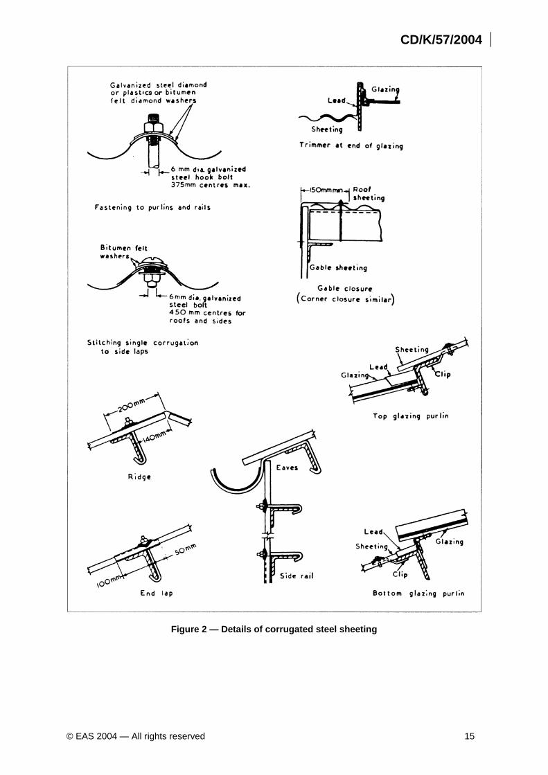
6.9 Methods of fixing the sheeting 6.9.1 General The sheets are fastened to steel angle purlins by galvanized hook bolts; to tubular steel purlins by U-bolts at lap joints and eaves, with J-bolts at intermediate purlins. Shot fired bolts and other specialized fixing methods may be used in conjunction with all types of steel purlins. The manufacturers should, however, be consulted to ensure that the strength is equivalent to orthodox fixings. See 7.6. Side laps or seams may be secured by galvanized steel bolts and washers. See 7.6. For timber purlins the sheets should be fixed with sherardized drive screws directly on to the purlins. The fasteners should be capable of resisting the effects of the wind as specified in ISO 4354. 6.9.2 Eaves and verges The ends of all sheets should be supported, and the support should be placed as near to the margin of the sheet as practicable. Galvanized steel sheets may be employed to secure the edges of the sheeting at verges, see Figure 2. Provision should be made in any case to secure the sheeting against uplifts by wind. 6.9.3 Top edges and abutments At a horizontal intersection of the roof with a wall, galvanized steel apron flashing pieces may be used. If the wall consists of vertical sheeting, the wall sheeting should lap over the upstand of the galvanized flashing pieces, and the apron should lap over the roof sheeting. Alternatively, lead or zinc flashing pieces may be used. At a sloping intersection, if the direction of the corrugation is parallel to the wall face, lead or zinc flashings may be used. The flashing should be dressed as an apron over the roof sheeting to cover at least one corrugation of the sheeting and, in any case, be not less than 150 mm wide. The upstand should be provided with cover flashings or should itself be turned into and secured to the wall. If the corrugations or flutes run into the wall face, the edge of the sheeting should be kept back at least 12.5 mm clear of the wall face, and a suitable gutter should be provided. If the corrugations or flutes run away from the wall face, normal flashings as for square abutments may be used. In both cases, lead or zinc flashings are required.
6.10 Pipes, etc., passing through roofing The positions of any necessary perforations should be considered during the design stage in relation to the position of the horizontal laps so that the length of lead or zinc flashing above the pipe outlet will not be unduly long. As an alternative to zinc flashing, special steel sheet soaker flange may be fabricated and, where necessary, galvanized after manufacture. Table 5 — Maximum permissible purlin spacings for limiting stress and deflection for pitched
roofs
Gauge
Total imposed load normal to roof slope (N/m2)
478.80 718.20 957.61 1197.01 1436.41
Corrugation Corrugation Corrugation Corrugation Corrugation
76.2 mm
127 mm 76.2 mm 127 mm 76.2 mm
127 mm
76.2 mm
127 mm
76.2 mm
127 mm
CD/K/57/2004
© EAS 2004 — All rights reserved 7
Purlin spacings
m m m m m m m m m m
14 3.43 4.80 3.05 4.34 2.82 4.04 2.67 3.81 2.51 (3.58)
16 3.20 4.57 2.90 4.11 2.67 3.81 2.58 3.53 2.36 (3.20)
18 2.97 4.27 2.67 (3.73) (2.44) (3.28) 2.29 (3.05) (2.21) (2.82)
20 2.82 (3.89) (2.51) (3.28) (2.21) (2.90) (1.98) (2.59) (1.83) (2.44)
22 2.74 (3.43) (2.29) (2.97) (1.98) (2.59) (1.83) (2.36) (1.68) (2.13)
24 2.44 (3.20) (2.06) (2.68) (1.75) (2.29) (1.60) (2.06) (1.45) (1.90)
26 (2.21) (2.90) (1.03) (2.44) (1.60) (1.83) (1.45) (1.90) (1.30) (1.75)
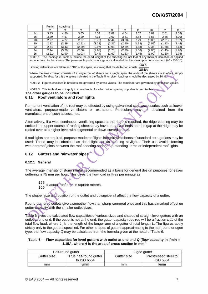
NOTE 1 The loadings in Table 5 include the dead weight of the sheeting but not that of any thermal insulation or applied surface finish to the sheets. The permissible purlin spacings are calculated on the assumption of a moment (M = WL/10).
Limiting deflections are taken as 1/100 of the span, assuming that the deflection equals EI
WL
384
3 3
Where the area covered consists of a single row of sheets i.e. a single span, the ends of the sheets are in effect, simply supported. To allow for this the spans indicated in the Table 5 for given loadings should be decreased by 10 %. NOTE 2 Figures enclosed in brackets are governed by stress values. The remainder are governed by deflection values. NOTE 3 This table does not apply to curved roofs, for which wider spacing of purlins is permissible.
The other gauges to be included
6.11 Roof ventilators and roof lights Permanent ventilation of the roof may be effected by using galvanized steel accessories such as louver ventilators, purpose-made ventilators or extractors. Particulars may be obtained from the manufacturers of such accessories. Alternatively, if a wide continuous ventilating space at the ridge is required, the ridge capping may be omitted, the upper course of roofing sheets may have up-curved ends and the gap at the ridge may be roofed over at a higher level with segmental or down-curved sheets. If roof lights are required, purpose-made roof lights integral with sheets of standard corrugations may be used. These may be obtained as dead lights or as opening skylights. Their use avoids forming weatherproof joints between the roof sheeting and the up-standing kerbs or independent roof lights.
6.12 Gutters and rainwater pipes 6.12.1 General The average intensity of storm rainfall recommended as a basis for general design purposes for eaves guttering is 75 mm per hour. This gives the flow load in litres per minute as
100
125 actual roof area in square metres.
The shape, size and position of the outlet and downpipe all affect the flow capacity of a gutter. Round-cornered outlets give a smoother flow than sharp-cornered ones and this has a marked effect on gutter capacity with the smaller outlet sizes. Table 6 gives the calculated flow capacities of various sizes and shapes of straight level gutters with an outlet at one end. If the outlet is not at the end, the gutter capacity required will be a fraction L1/L of the total flow load, where L1 is the length of the longer arm of a gutter of total length L. The figures apply strictly only to the gutters specified. For other shapes of gutters approximating to the half-round or ogee type, the flow capacity Q may be calculated from the formula given at the head of Table 6.
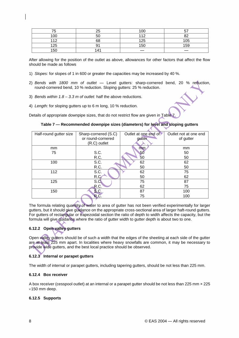
Table 6 — Flow capacities for level gutters with outlet at one end Q (flow capacity in l/min = 1.15A, where A is the area of cross section in mm
2
Half-round gutter Ogee gutter
Gutter size True half-round gutter to ISO 6564
Gutter size Prestressed steel to ISO 6564
mm l/mm mm l/mm
8 © EAS 2004 — All rights reserved
75 25 100 57
100 50 112 82
112 68 125 105
125 91 150 159
150 141 — —
After allowing for the position of the outlet as above, allowances for other factors that affect the flow should be made as follows 1) Slopes: for slopes of 1 in 600 or greater the capacities may be increased by 40 %. 2) Bends with 1800 mm of outlet — Level gutters: sharp-cornered bend, 20 % reduction,
round-cornered bend, 10 % reduction. Sloping gutters: 25 % reduction. 3) Bends within 1.8 – 3.3 m of outlet: half the above reductions. 4) Length: for sloping gutters up to 6 m long, 10 % reduction. Details of appropriate downpipe sizes, that do not restrict flow are given in Table 7.
Table 7 — Recommended downpipe sizes (diameters) for level and sloping gutters
Half-round gutter size Sharp-cornered (S.C) or round-cornered
(R.C) outlet
Outlet at one end of gutter
Outlet not at one end of gutter
mm mm mm 75 S.C. 50 50
R.C. 50 50
100 S.C. 62 62
R.C. 50 50
112 S.C. 62 75
R.C. 50 62
125 S.C. 75 87
R.C. 62 75
150 S.C. 87 100
R.C. 75 100
The formula relating quantity of water to area of gutter has not been verified experimentally for larger gutters, but it should give guidance on the appropriate cross-sectional area of larger haft-round gutters. For gutters of rectangular or trapezoidal section the ratio of depth to width affects the capacity, but the formula will give guidance where the ratio of gutter width to gutter depth is about two to one. 6.12.2 Open valley gutters Open valley gutters should be of such a width that the edges of the sheeting at each side of the gutter are at least 225 mm apart. In localities where heavy snowfalls are common, it may be necessary to provide wide gutters, and the best local practice should be observed. 6.12.3 Internal or parapet gutters The width of internal or parapet gutters, including tapering gutters, should be not less than 225 mm. 6.12.4 Box receiver A box receiver (cesspool outlet) at an internal or a parapet gutter should be not less than 225 mm × 225
150 mm deep. 6.12.5 Supports
CD/K/57/2004
© EAS 2004 — All rights reserved 9
Pressed steel gutters should be supported by a bracket at each joint and each length in excess of 1.2 m should be provided with an intermediate bracket. If other materials are used the manufacturer’s recommendations should be observed.
6.13 Walkways and roof-boards 6.13.1 General Where a roof is likely to need periodical attention, properly constructed walkways or roof-boards should be provided to give access to roof lights or other places to prevent injury to workmen and damage to the roof sheeting. 6.13.2 Permanent walkways Permanent walkways should be properly designed and securely fixed to the roof structure. They should be at least 430 mm wide and should be supported clear of the roof sheeting. Handrails, if supported, should be at least 900 mm high above platform level. 6.13.3 Roof-boards If permanent walkways are not provided, roof-boards or cat ladders should be available for use at any time that inspection or repairs to the roof are necessary. They should be so designed, constructed and supported that there is no risk of displacement or tilting. They should be at least 375 mm wide, and the battens or steps should on no account project beyond the edges of the boards, stringers or bearers. Adjacent roof-boards should not be butted end to end but should be lapped or staggered, preferably over a purlin.
7 Application
7.1 Safety precautions As far as is practicable no persons other than workmen employed by the roofing contractor should be permitted access to any area over which the sheeting is being laid.
7.2 Ladders, scaffolding and hoists To avoid unnecessary erection of plant for roof-covering work, use should be made of any suitable scaffolding, ladders or hoists that have been erected for other building operations. The responsibilities for the provision and use of plant should be agreed before the contract is made.
7.3 Storage and handling of sheets at suppliers stores or on site 7.3.1 General Galvanized steel sheets will store almost indefinately in a warm, dry, clean atmosphere. It should be emphasized that if moisture is allowed to condense between the sheets it will cause white or black rust, which will reduce their resistance to corrosion. Therefore, it is advisable to separate the sheets and stack them on end on timber battens. Pretreatment can be specially ordered and will reduce the risk of white or black rust. Care should be taken that sheets and fittings are not damaged during handling or transport. They should be kept clear of dirt and harmful chemicals. 7.3.2 On site All sheets and fittings should be stacked as described in 7.3.1 in dry, sheltered positions as near as possible to the parts of the building on which they will be fixed. All sheets and fittings including gutters and downpipes fixing bolts and screws and any accessories required should be on site or available before the work is commenced. Sheets should preferably be kept on timber battens in the bundles or packs in which they leave the works. Where slings or grabs are used they should be suitably arranged to avoid sheet edges.

10 © EAS 2004 — All rights reserved
7.4 Preparation of sheet for roofing and vertical cladding The holes for the fixing bolts should be made through the crown of the corrugation and should be either punched or drilled. They should be 1.5 mm larger in diameter than the bolts or fixing screws used. Holes for fixing the sheets should be in exact positions to suit the purlins, i.e. as close as possible to the back of the purlin of steel angles are used, or on the centre of the purlins if they are of timber. No hole for a fixing bolt should be nearer than 38 mm to the end of a sheet.
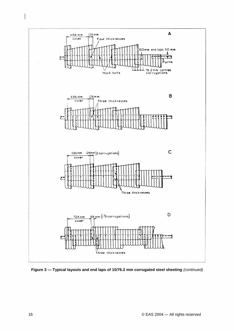
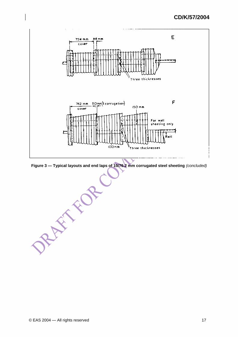
7.5 Layout of the sheeting The purlin spacing and the length of the sheets should first be checked to see that the arrangement will provide the specified overhang at the eaves and the laps. The eaves course should be laid first and work should start at the leeward end of the building, so that the side laps will have the better protection from rain driven by the prevailing wind. The top edges or eaves sheets should extend at least 38 mm beyond the back of steel angle purlins or 75 mm beyond the centre line of timber purlins. At side laps, where the edge corrugations of the sheets are to opposite hand, the underlapping sides should finish with an upturned edge and the overlapping sides with a downturned edge. At abutments, the sheets should finish with an upturned edge, where possible, to save an undue width of flashing. Arrangements for laying sheets are shown in Figure 3; Method A is customarily used. Curved sheets, if used, should be laid in a similar manner, but on the upper and flatter parts of the roof where the pitch is less than 20°, end laps should be increased according to the degree of exposure and, if necessary, bedded with mastic
7.6 Fixing the sheets Galvanized corrugated steel sheets are normally fixed to steel angle purlins by hook bolts, or to timber purlins by mushroom-headed drive screws. Where sheets finish against the upper or lower edge of roof glazing, they are usually held in position by special joggle-bar clips if steel angle purlins are used. Hook bolts and drive screws are of either 8 mm or 9 mm nominal diameter, spaced at intervals of not more than 375 mm. Sheets should be secured at every purlin by at least two bolts. Fixings to tubular purlins should be of equivalent strength (see 6.9). Where single side laps are used on sheets thinner than 0.7 mm the seams should be secured by means of galvanized steel bolts or self-tapping screws of 6 mm diameter and washers spaced at intervals of not more than 450 mm. The nuts of hookbolts, or the heads of drive screws, should bear on purpose-made washers to render the bolt hole weatherproof. Washers are to be of galvanized steel (diamond shape for hook bolts) bedded on bituminous felt or other plastics limpet washers. The screw or bolt should be tightened sufficiently to seat the washers over the corrugation. All holes for fixing, if punched in position, should be supported on the reverse side.
7.7 Fixing of accessories 7.7.1 General Accessories should be secured, where possible, by the same bolts that secure the sheeting. If this is not practicable, bolts may be used to secure the accessory to the sheeting. 7.7.2 Ridge cap
CD/K/57/2004
© EAS 2004 — All rights reserved 11
The ridge cap may be secured to the ridge purlins by the same bolts that secure the sheeting; if the ridge purlin is not sufficiently near the ridge to permit this, the capping should be secured to the sheeting by 8 mm roofing bolts, two roofing bolts to each wing of the capping at centres not further apart than the bolts used for securing the sheeting. The lap of the cap along the ridge should be not less than 150 mm and so arranged to protect the joint from the prevailing wind. 7.7.3 Hip cap The roof sheeting at hips should be cut to the required mitre and be close butted. The hip joint may be covered with plain ridge cap, which should be secured through the roof sheets or the hip runners by one bolt on each side at the same spacing as for the roof sheeting. Hip caps should have a 150 mm lap. With timber purlins, the hip capshould be fixed to the rafter by means of drive screws. At the intersection of two hips with the ridge, the sheeting should be mitred and close butted, the intersection at the junction being covered with a suitable saddle. The ridge and hip capping should be mitred together and secured with bolts as previously described in 7.7.2.define the word mitred 7.7.4 Other fittings Other galvanized steel accessories should be securely bolted either to the structure or to the sheeting.
8 Inspection on site Before sheeting is commenced, the structure should be inspected to see that all purlins and sheeting rails are in a true plane, correctly spaced and securely fixed. All structural steelwork should be painted or otherwise protected from corrosion. During progress of construction the work should be inspected to see that all units are correctly laid as regards bearing on supports and that the minimum laps are provided. All fixing bolts, screws and washers should be of the specified type and size, and should be in correct position and secure. The sheets should be checked for alignment; corrugations of the sheeting should be in line from eaves to ridge; all flashings should be secure and close fitting, with ample lap.
9 Maintenance
9.1 General The sheeting should be examined periodically; any damaged units should be replaced or repaired promptly, and flashings re-dressed, if necessary.
9.2 Need for painting Provided that the conditions of 7.3 have been complied with and that proper care has been taken to ensure arrival of the sheets on site in good condition, it is not generally necessary, in clean atmospheres, to paint galvanized corrugated steel sheet roofing. In certain atmospheres corrosion would commence at the overlaps and in such conditions overlaps should be painted before laying. Under severe conditions regular attention to painting will ensure indefinite life. In common with other roofing materials, painting is essential where the metal is in contact with building materials containing alkalis (e.g. concrete and mortar) or with hardwoods containing acids (e.g. oak) or with other metals.
9.3 Paints suitable for galvanized sheets 9.3.1 On new galvanized sheets it is preferable to use paints that will adhere without the application of mordant solution. Among others, paints pigmented with zinc dust, zinc oxide, calcium plumbate or zinc chromate are suitable for the purpose.
12 © EAS 2004 — All rights reserved
9.3.2 In addition to the paints mentioned in 9.3.1, paints may be used consisting of pigmented mixtures of zinc chromate and red oxide of iron; For a finishing coat, if specified, any good paint based on a drying oil, oleo-resinous, synthetic, bituminous or other suitable medium may be used. Some suitable finishing paints are pigmented with aluminium, red oxide, Such paint systems are suitable for severe exposed conditions as occur in industrial or marine atmospheres.
CD/K/57/2004
© EAS 2004 — All rights reserved 13
Annex A
Thermal transmittance (U value) Data are given below by means of which the loss of heat through a galvanized corrugated steel sheet roof may be estimated for various methods of construction. The actual rate of heat loss depends upon the difference in temperature between the inside and outside air, and on the thermal transmittance, U, of the construction. The thermal transmittance is defined as the number of watts transmitted through one square metre of the construction when a temperature difference of 1 °C exists between the air on the two sides of the construction. Approximate values of U are given below for various types of roof construction. These values may be used for most situations in this country. The colour of the paint, if any, or whether the surface is dirty or clean has little effect on the thermal transmittance of a galvanized steel sheet roof. For vertical cladding, the U value for galvanized corrugated steel sheet may be taken as 9.8. When insulated the values can be taken, for practical purposes, as those given below for a roof. Manufacturers of proprietary thermal insulating materials and fixing systems will supply full details of the insulating and other properties of their product if required. The following example is intended as an approximate guide:
Method of roof construction U value W/(m
2 °C)
Uninsulated galvanized corrugated steel sheet 8.5
Galvanized corrugated steel sheet with an air gap (25 mm minimum) provided by:
Insulation board 6 mm thick 2.30
Insulation board 12 mm thick 1.70
Insulation board 25 mm thick 1.25 NOTE 1 unit (R) ft2 H °F/BTU 0.1761 = 1 unit m
2 °C/W.
1 unit (U) BTU/ft2h °F 5.678 = 1 unit W/(m
2 °C.)
14 © EAS 2004 — All rights reserved
Figure 1 — Typical sheets and side laps
CD/K/57/2004
© EAS 2004 — All rights reserved 15
Figure 2 — Details of corrugated steel sheeting
16 © EAS 2004 — All rights reserved
Figure 3 — Typical layouts and end laps of 10/76.2 mm corrugated steel sheeting (continued)
CD/K/57/2004
© EAS 2004 — All rights reserved 17
Figure 3 — Typical layouts and end laps of 10/76.2 mm corrugated steel sheeting (concluded)

© EAS 2004 — All rights reserved