easy install outboard motor mount
TRANSCRIPT

Central Washington University Central Washington University
ScholarWorks@CWU ScholarWorks@CWU
All Undergraduate Projects Undergraduate Student Projects
Spring 2018
Easy Install Outboard Motor Mount Easy Install Outboard Motor Mount
Doug Dunbar [email protected]
Follow this and additional works at: https://digitalcommons.cwu.edu/undergradproj
Part of the Mechanical Engineering Commons
Recommended Citation Recommended Citation Dunbar, Doug, "Easy Install Outboard Motor Mount" (2018). All Undergraduate Projects. 72. https://digitalcommons.cwu.edu/undergradproj/72
This Dissertation/Thesis is brought to you for free and open access by the Undergraduate Student Projects at ScholarWorks@CWU. It has been accepted for inclusion in All Undergraduate Projects by an authorized administrator of ScholarWorks@CWU. For more information, please contact [email protected].

Easy Install Outboard Motor Mount
Doug Dunbar
In Association with:
CWU MET Faculty and Peers


Abstract:
The boating industry can be expensive for the typical weekend boater. That is, keeping,
maintaining, and using a boat and all of its various accessories is a constant cost for the owner. In
the Midwest and inland it is necessary to store boats and outboard boat motors out of the
inclement weather and harsh conditions of seasonal change. Specifically, removing or installing
an expensive and awkward outboard motor can be both dangerous financially and physically
(damage or injury). It is not uncommon for motors to cost several thousand dollars.
The purpose of this project was to research, design, and implement a rugged, easy to use
outboard motor mount that helps the user both install and uninstall their outboard motors in a
safe way. It was imperative that the design be applicable to many outboard motor designs and
handle the stresses caused by the use of these motors. By using 3D modeling software and
sample boats and motors the designer was able to design and construct an effective solution to
these problems.
This project resulted in a design that allowed the user of the motor to not have to induce a
force of more than a third of the weight of the outboard motor, install their motor in less than 30
minutes while alone, and do all of this safely. Through frictional and torque analysis the designer
was able to meet these goals and more, in this paper the process of the design, construction, and
testing will be presented in detail.

Section 1: Introduction and Description
Introduction:
Boats can come in a variety of shapes and sizes but one thing they all have in common is
that they must dock, or come back to land at some point. Take for example, a 25 foot Bayliner
with a 300 Horsepower inboard engine. Out in open water this engine supplies the boat’s main
power and serves the vessel well in terms of locomoting quickly and safely to the destination.
However, once the boat has reached its slip or “parking spot”, the inboard engine is inappropriate
and actually quite ineffective for small maneuvers in the tight spaces of a bay. This is where the
outboard motor comes into play. With a relatively small 20 Horsepower outboard motor, a
captain can easily, slowly, and safely maneuver the large vessel into its respective docking slip.
The problem that is found with the 25 foot Bayliner is that its owner typically uses the
vessel in solo. Ordinarily, this may not seem like an issue but when the seasons change and the
cold sets in for the winter it is wise for boaters to shelter their boats and motors from the
inclement weather. Specifically, the outboard motor is susceptible to seasonal damage if left
unattended in the Ellensburg winters where the temperatures have been known to drop to below -
10F. Herein lies a problem that will be investigated further in this document: the installation and
removal of an awkward, expensive and heavy motor from its boat can be both dangerous and
financially risky for the boater as most new outboard motors pricing ranges from $500-$3,000!
The customer and motivator for this project currently owns an outboard worth more than $2,500
therefore, a device that safely removes and installs the motor on and off of the boat is needed.
This proposal will provide the data, calculations, interpretations, trials, and errors of the
manufacturing and testing of an outboard motor mount that can install and uninstall an outboard
motor by one user with little to no effort or risk.
Motivation:
The driving force behind this project is to design a product that will allow elderly or disabled
folk to install and remove their outboard motors without risking bodily or financial harm.
Function Statements:
● This mount will have to withstand the stresses of the motor at full speed.
● The mount must lower the motor safely onto its storage rack for the off seasons.
● The mount must lift the motor onto the boat safely from its storage rack.
● The outboard motor mount will adjust height easily with one hand operation.
● The mount will lower the motor to a height that allows for safe transfer to the storage
rack.
● Motor mount can install the motor with one person.
● The mount does not lose integrity with frequent use.
Requirement Statements:
● Will not require more than ⅓ the weight of the motor to adjust the motor height.
● Will withstand the stresses of a 20 horsepower motor at full speed and any angle.
● Will not require more than one person to install and uninstall the motor.
● Installation or uninstallation of the motor takes no more than 30 minutes.
● All load bearing parts deflect no more than +/- .35 inches under load.

Success Criteria:
● The motor can be lifted without using more than 38lbs (115lbs/3) of force at any time
● The mount will withstand the tests of time (years of use)
● The motor may be installed by a single user
● The installation of the motor takes no more than 30 minutes
● No part will deform but may deflect up to .35 inches in the direction of the loading
Scope:
The scope of this project includes designing, modeling, manufacturing, testing, and
utilizing of the motor mount.
Engineering Merit:
Currently there are no motor mounts that allow for a user to safely install their outboard
motors which they cannot lift themselves. This project also opens doors to creating disassemble-
able lifting/crane type apparatus’ on boats.

Section 2: Design and Analysis
Design Development:
The main problem faced by the designer throughout the design of this product was not
meeting the requirements of deflection or mass but the function statements. This product has not
been commercialized and as such has no precedent or previous version to relate to.
The base plate is the foundation for the entire apparatus and as such the designer decided
it would be best to oversize the part dimensions and allow for significant error as well as
variability in what size of motor can be installed. Welded onto the top of the base plate are the
extension bracket seats. These consist of 2 inch square tubing with ¼’’ walls. These seats will
house the lifting arm supports or “L” supports. The lifting arm supports are shaped like an “L”
and will serve a few purposes: supporting the weight of the motor, locating the motor far enough
out from the swim platform so that the motor can pass it safely, and lifting the motor high
enough such that the motor clamp seat can be pushed underneath the motor clamp to receive the
motor. The motor clamp seat consists of two parts: the seat and the telescoping arm support. The
seat will be made of steel and will serve to be the part that the motor itself will clamp on and
secure to. The telescoping arm support will consist of two parts as well: the telescoping arm, and
its seat. The arm will be made of 1 inch square steel bar and will slide in and out of the
telescoping arm seat. The arm seat will be 1.5 inch square tubing with ¼’’ walls. These
dimensions allow for the arm seat and the arm support to mate and slide to reposition the motor
during use, install, and uninstall.
The lifting of the motor will be done by hand crank. The hand crank will be bolted to the
rear of the base plate and will have at least a 10:1 ratio of force in its leverage. The hand crank
will transfer the force of the user through parachute cord that will wrap around the lifting axle
which is axially located on the top of the extension arm supports. The rope will attach to the
counter-moment device. Once a secure connection is achieved the user may lift the motor via
hand crank and begin the installation process.
The success of this project hinges entirely on the functionality of the aforementioned
part: the counter-moment. This part is highly experimental and unprecedented as its design is to
redistribute the forces of the weight of the motor such that it will lift with its clamp parallel to the
motor seat. This is tricky because the motor, lifted from its clamp, lifts at an angle that doesn’t
allow for easy installation of the motor seat into the motor clamp. Without the parallelism
between the clamp and seat the motor will not be able to be inserted into the seat and this will
result in failing to meet the function statement of safely securing the motor onto the vessel
without lifting with the body.
Design Description:
Many iterations of this product have been evaluated and the most effective proposed
solution is as follows. The mount will function like a static normal motor mount that can be seen
already in use in many boating applications. The base of the mount will be altered such that it
will have removable motor installation parts as shown in the 3D model. The removable
installation parts will allow the motor to be lifted by the hand crank and mated with the receiving
bar. Removal of the motor from the mount will be a similar process to the installation but
reversed. One advantageous quality of the design proposed is that the motor mount has the
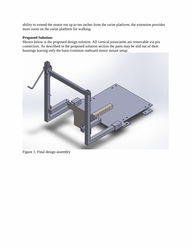
ability to extend the motor out up to ten inches from the swim platform; the extension provides
more room on the swim platform for walking.
Proposed Solution:
Shown below is the proposed design solution. All vertical joists/arms are removable via pin
connection. As described in the proposed solution section the parts may be slid out of their
housings leaving only the basic/common outboard motor mount setup.
Figure 1: Final design assembly

Figure 2: Assembly during Boating Season
Description of Analysis:
Much of the projects area of interest when it comes to the engineering analysis is from
the deflection and/or deformation of parts under loading. For all calculations a safety factor of at
least 2 is used as the designer requires that no part deflects more than .375 inches.

Section 3: Methods and Construction
Methodology and Construction:
This project will involve several professional disciplines. To name a few: metallurgical in
the choosing of material and how it will be affixed in the assembly, mechanical in designing the
force requirements of the build, turning, milling, welding, and drilling in the construction of the
assembly, and stress analysis in determining the deflection and or deformation of the parts under
loading. The project revolves around the marine environment and hinges on the general
endurance and durability of equipment in water. A general knowledge of the problems faced by
boaters and captains is provided by the designer and the customer, both seasoned boaters. This
knowledge provides the designer the requirements of the user and the parameters enforced by the
dimensions of the boat and user. Because the proposed solution involves mechanisms that reduce
effort through leverage mechanical engineering and static analysis is necessary. Moreover, the
fact that the product will be made solely of steel requires the designer to understand the
deflections and changes in shape of the product under load and during use. Equations of interest
throughout the analysis of this project are as follows:
PL^3/3EI=Deflection
F/A=Stress
V/A=Shear Stress
I=1/12(b) (h^3)
M=Fd
F=umg
Benchmarks:
Benchmarks are outlined in the Gantt chart by the blue triangles and arrows.
Construction Methods:
The construction of this motor mount will be in three stages. The first stage will consist
of dimensioning the parts to be the correct size and shape. This aspect of construction may
involve cutting, grinding, filing, and machining of parts to fit their design requirements. The
second stage of construction will consist of adhering the permanent parts of the design onto the
base plate. This stage will involve welding of four main parts shown in the 3D model. The final
stage of the construction will be assembly. Some of the main parts of the lifting apparatus are
designed to be removed after the installation and will therefore require installation themselves.
Update (3/15/18):
As predicted much of the design called for cutting, turning, welding, filing, and grinding.
One aspect that was not predicted was the bending of the hand crank. This was performed by
torching the end of the hand crank after it had been turned to slip into the lifting axle hole and
using an anvil to bend it at roughly a right angle. All other predictions of the construction of the
project were accurate and useful. One discovery that changed the construction schedule of the
device was that the designer was, for lack of better terms, rusty with his skills in the workshop.
This lead the designer to reconsider the hours allocated for the construction of the device. The
project schedule was still maintained but extra time had to be predicted in the construction phase
of the device.

Drawing Tree:
Shown here is the full and up to date drawing tree outlining all parts in the assembly and their
relative mating parts.
Figure 3: Drawing Tree

Parts List:
# Part Material Dimensions
1 Base Plate A36 .25x24x24’’
2 ¼” Rectangular Tubing A36 12’x1.5’’x1.5’’
3 Mount Plate A36 12”x24”x1/4”
4 Pin A36 2(.375’’x3.5’’)
5 Pin A36 .375’’x2.5’’
6 Bushing
Impregnated
Bronze 1.5”x.875”IDx1.0”OD
7 Lifting Axle A36 1”x24”
8 Counter Moment A36 4’x1.5” Round Tubing
9 ¼” Tubing A36 12”x2’’
Expected Manufacturing Issues:
As shown in the assembly picture in Section 2, the counter moment part has dimensions
such that it will experience a very concentrated load at its corners. It is expected that this part
may fail under loading and due to the constrictions of the designs requirements may require a re-
design. This part is experimental and as such has the potential to exhibit unforeseeable behaviors.
Discussion of Assembly:
Shown below is the final design assembly in isometric view. As noted in appendix B1-16
parts included in view are: Hand crank, dog, pawl, lifting axle, bushings, alignment bracket,
counter moment arms, counter moment pegs, lifting arms, lifting arm brackets, receiver bar, bar
receiver, mount plate receiver, mount plate, .375x 3.5” pin, and swim platform brackets.

Figure 4: Assembly Final Design

Construction Visual Documentation:
In the following images the designer will describe the construction and design of all parts
included in the design.
Figure 5: Lifting Axle
Shown above is the lifting axle. This image shows the axle after it has been turned to accept the
bronze bushings purchased on 2/20/18.

Figure 6: Counter Moment Peg Prior to Welding
Shown above is the counter moment peg and mount plate assembly. The slotted peg will slide
onto the mount plate and be welded in place. The construction of this assembly was
unconventional. Due to the limited machinery in the CWU shop the only viable option for
manufacture of the pegs was to use the upright mill. The slot was slowly cut away from the solid
round peg. During manufacture the designer unfortunately broke two ¼” end mills, this was
expected according to the shop hand Matt Burvee.

Figure 7: Counter moment pegs after welding
Shown above is the counter moment slotted peg after it has been welded onto the mount plate.
The activity is that of removing material that wouldn’t allow for the counter moment arms to be
pin connected to the pegs. By using a dremel Nolan Stockman and the designer were able to
remove enough material from the mount plate for the counter moment arms to be installed easily.

Figure 8: Pawl soft jaws
Shown above is the Pawl of the Dog & Pawl system designed to inhibit the axle from rotating
under the static loading of the motors weight. This is an absolutely necessary part as it prevents
the motor from dropping unexpectedly. The design was reflective of those shown on McMaster
Carr. This part took approximately 2.5 hours to produce and was worthwhile as the other option
was to spend at least $46.00 on one available on McMaster Carr. Due to its odd shape custom
soft jaws had to be turned on the lathe. The lathe was necessary to produce the hole in the Pawl.
This hole will go around the lifting axle and be welded together. The “teeth” were cut with the
Torch Master Plasma cutting table. The material for this part was donated by Nolan Stockman.

Figure 9: Depiction of assembly as of 2/16/18
Shown in the above image is the lifting arm assembly clamped onto the base plate. It was here
that the designer discovered how difficult it was to rotate the lifting axle. Note the lack of
bushings and the roughness of the round bar surface. Parts also seen in the image: receiver arm,
receiver arm seat, lifting arm seats, lifting arms, mount plate, and base plate.

Figure 10: Hand Crank after turning, welding, and drilling.
Shown above is the hand crank mechanism. This A36 Steel round bar was cut, turned, heated
and bent. The installation of this part is simple. The bent side will act as a handle for the user and
the other end will be inserted into the lifting axle. The insert had to be turned to fit into the
specified hole on the lifting axle. The pinhole jig was used in the manufacture of this part to
fasten the hand crank to the lifting axle as shown on the left.

Figure 11: Receiver bar and mount plate receiver completed
Shown above is the receiver bar and mount plate receiver. The bar was a difficult piece to
produce because, by the designers fault, this part was not ordered to mate. The design of this part
requires it to mate with the receiver tube as shown below. It was later discovered that these types
of parts can be ordered with dimensions that already mate. Due to this error the designer spent
several hours milling off the corners and the faces of the square bar in order to make it slide
easily in and out of the receiver tube. The holes are one inch apart and allow the user to adjust
the distance of the mount plate from the swim platform. The pins have been punched with the
letter “R” for “receiver” so that the user may save time when installing the many pins of the
assembly.

Figure 12: Receiver bar and mount plate receiver and receiver tube welded onto base plate.
Shown above is the receiver bar mated with the receiver tube and mount plate receiver. At this
setting the mount plate would rest 4 inches from the edges of the swim platform (the edge of the
base plate). The receiver tube has been welded onto the base plate and will effectively support
the motors weight and forces.

Figure 13: Counter moment assembled onto mount plate
Shown above is the mount plate being inspected for functionality. The counter moment pegs
have been welded into their final place and the counter moment arms have been installed and
attached to the lifting axle via parachute cord. If analysis proves valid the counter moment arms
will redistribute the forces of the weight of the motor such that they create a moment that will
counter the torque generated by the off-center center of mass of the motor resulting in a parallel
positioning of the mount plate to the receiver bar.

Figure 14:
Shown above is the mount plate and its 5/16th” bolts, counter moment arms, counter moment
pegs, and lifting rope.

Figure 15:
Shown above is the dog and pawl system after it has been fully constructed and assembled.

Figure 16:
Shown above is the right side view of the final assembly. Compared to Appendix B16 it is
effectively the solidworks design transferred into reality.

Figure 17:
Shown above is the alignment bracket in action. Note that it’s design will not interfere with the
rotation of the axle and the wrapping of the lifting rope. See Appendix B14 for manufacture
drawing.

Figure 18:
Shown above is the top view of the final design. Note its similarity to Appendix B17 the top
view of the manufacture assembly drawing.

Figure 19:
Shown above is the lifting arm assembly installed onto the base plate. These arms are entirely
removable as can be seen by their pin connections on the base plate. The lifting axle, shown in
the top left of the image displays the Oil Impregnated Bronze Bushings noted in Appendix B15.
These bushings are press fit onto the lifting axle and serve to reduce the friction of rotation.

Section 4: Testing & Analysis
Introduction:
As stated in the requirement statements the motor mount will:
1. withstand the stresses of the motor with a safety factor of two during the installation and
uninstallation
2. be designed so that installation or uninstallation of the motor onto the mount takes no
more than thirty minutes with one person
3. not require more than 38 pounds of force to install or uninstall the motor
Predicted values for each of the three mentioned tests can be found in the Appendix A
section. Noted in A15-16 are the predicted results of the force analysis, specifically the hand
crank force. Deflection analysis of each loaded part may be found throughout the appendices.
Loaded parts of interest are A3, 4, and 5. The installation time predicted value is based on the
estimated assembly time of the designer, throughout manufacture assembly was required several
times without the motor being involved. Without the motor, assembly took roughly ten minutes,
another twenty is the likely to be sufficient to safely install a motor with the device. Data will be
acquired as outlined in the Gannt Chart attached. See section C, figures 58 and 59 in Appendix
14.
Methods and Approach:
The first requirement will be first tested mathematically through the analysis of the
bending of the motor mount setup pieces. Permanent deformation is not permissible in any of the
pieces, the maximum deflection of any piece shall not exceed .375in. To test this the designer
will clamp each loaded part individually to a testing table that is known to be both flat and rigid,
in the machine shop room 107 in the Hogue Technology Building at CWU, the knee of the
horizontal mill shall suffice. The designer will load each part on their end with the design load of
230lbs (F.S. = 2) and record any deflection with a dial indicator. Data will be recorded three
times for each part and averaged. Data is shown in Section 18 Testing Report.
The second requirement will simply be tested by assembling the lifting mechanism and
installing/uninstalling the motor. This test requires that each part be fully manufactured and
ready for testing. The designer will start by demonstrating the procedure for installing the motor
to the customer while being timed. After the designer has completed an installation the customer
will then attempt to perform the installation procedure in less than thirty minutes. The
uninstalling of the motor ideally will take less than thirty minutes, but this was never a proposed
test or design parameter and will not be tested. Together, the designer and customer will propose
optimizations in the installation procedure. This, if necessary will result in faster and safer
installations with this design and potentially spur design modifications or complete redesigns.
Data will be collected by using a timer at the start and end of the installation process. Video
recording will also be used to provide viewers the chance to understand the operations of the
device.
The testing of the third requirement will require the mount to be fully constructed and
assembled. This test will use the hand crank of the lifting mechanism. The cranking of the hand
crank will require the user to apply a force to the handle. The force will not exceed 38 pounds of
force when rotating the handle. Another aspect of the 38 pound force limit will be in the setup of

the motor install apparatus. The removable pieces should not weigh more than 38 pounds each.
As noted in Appendix A15-16 the force required to rotate the lifting shaft is calculated to be
approximately 25lbs. If this calculation is accurate then this portion of the project requirements
will be a success. This test will require a fish scale, a spring-loaded scale to measure the force
required to rotate the hand crank. The scale will be affixed to the handle of the hand crank most
representative of where a user would place their hand. Data will be recorded at four locations and
averaged, the four points are located at 0, 90, 180, and 270 degrees from normal +/- 15 degrees.
The motor will have to be lifted completely off the ground and hanging by the lifting ropes
attached to the lifting axle for each position. Measurements shall be taken throughout the entire
lifting distance spanning 36 inches and requiring 11 full rotations; 44 data points will be taken
and averaged to provide a relatively accurate assessment of force. Data will be presented below
in the results subsection of Testing & Analysis.
Analysis Update (2/22/18):
The lifting axle was purchased as a solid round 1” bar of A36 steel. This axle was
received notably out of round ie. it was bent slightly. This observation lead the designer to
calculate the potential frictional resistance added by the out of roundness and/or friction. As
noted in Appendix A15 the frictional forces exceeded the force requirement maximum of 38lbs,
the force was calculated to be 64 lbs. As a result the designer opted to purchase two oil
impregnated bronze bushings. The shaft was then turned and polished to allow for a press fit of
the bushings onto the shaft. Once the lifting apparatus was assembled it was notably easier to
rotate the shaft, calculations support this observation and the resulting force required to rotate the
shaft was calculated to be approximately 25lbs. These calculations provided for a 60% reduction
in force required to rotate the shaft. During the testing phase the exact amount of force required
to rotate the shaft will be determined.
Analysis Update (3/01/18):
The assembly of the lifting arms apparatus was designed to be put together using cotter
pins only at the beginning of the construction phase. It was realized, after completing the original
design construction, that the apparatus has a significant flaw. Due to the simplicity of the design
the apparatus doesn’t maintain axial alignment. This flaw made the apparatus both hard to install
and use because the lifting axle would not align well with its shaft holes located in the lifting
arms. On the first of March the designer went back to SolidWorks and designed a simple but
highly effective alignment bracket (see appendix B16) to solve this problem.

Section 5: Budget & Schedule
Introduction:
The components of the motor mount are as shown in the image below. Much of the
design is built out of ¼” rectangular tubing and ¼” plate. The whole of the project consists of
A36 Mild Steel for both affordability and durability. With customization in mind the designer
and customer opted to oversize much of the design. In the design there are five welding sites: the
two lifting arm seats, the lifting arm elbows, the receiver bar, the counter moment slotted pegs,
and the dog & pawl.
Figure 20: Final design Assembly
Parts Suppliers:
Two main part suppliers are of interest in the construction of this project. The CWU
machining lab may provide material and tool access to Senior project students. The designer
plans to utilize the lathe, drill press, Bridgeport mill, and band saw that are available in the
machine shop. Matt Burvee will be the supplier that is found at CWU. The other parts supplier
that will be useful in this project goes by the name of Metals Depot found online and in the
references section. Once all parts and components are established these two suppliers will be
contacted and quoted and compared against each other. As winter quarter approached the
designer was forced to purchase parts and materials from Metals Depot as the faculty at CWU
were unreachable. Once the quarter began the CWU faculty were able to cost effectively replace
Metals Depot as a supplier. The CWU faculty have provided access to machinery, tools, and
measurement devices as well as several bolts, nuts, and cotter pins (2/28/18).

Labor:
Shown in Appendix C1, the designer requires a modest compensation of $1.25/hr of
labor. According to the Gantt Schedule the estimated project duration will be 150.00 hours
resulting in a fee of $187.50. Contracted hours are predicted to be approximately 5 total and at a
rate of $15.00/hr will result in a fee of $75.00.
Estimated Project Cost:
Outlined in Appendix C1, the total project cost is predicted to be $487.41. This is within
the allowable budget and will allow for the potential failure of the aforementioned part, the
counter moment, and it’s re-design and replacement.
Funding:
The funding for this project will be supplied entirely by the customer: Larry Dunbar. The
price limit has been set at $550.00 for all components and labor costs. See Appendix D1 for a
more detailed analysis of the costs associated with this project.
Proposed Schedule:
Shown below is the example schedule of what was accomplished and completed during
the fall quarter. The schedule for this project will be in Gantt style and blue triangles in the table
will represent project milestones. The light green cells indicate the weeks in which those tasks
are completed throughout the quarter.
Figure 21: Gantt Schedule example
Estimated as well as actual task duration is shown. Shown at the bottom of the table is the
subtotal for the quarter in hours, the quarter total duration was seen to be 32.75 hours. Charts
with greater detail for Fall, Winter, and Spring quarters may be found in Appendix E.
Schedule Update: (3/01/18)
Parts that were scheduled to arrive before the quarter began arrived according and
manufacture began right away. As can be seen on the Winter Quarter Schedule in Appendix E
(Figure: 56, 57, 58) construction began and ended according to the Gantt Schedule. One
discovery was that the manufacture of each part had its own intrinsic complications in that some
of the parts were unconventional and/or difficult to produce using the CWU machine shop
machinery. Manufacturing issues can be seen in the drawings appendix B with the Counter
Moment Pegs and the lifting arm holes. This issues was resolved by the designer allocating more

time for the construction of each part. As shown in appendix E the actual duration of the
construction phase of the project exceeded the predicted time by approximately 7.5 hours. This
extra time for construction was found in the early mornings when the CWU machine shop was
relatively unoccupied and many of the machines were not in use. It was also discovered that
hours past the noon hour were the busiest for the CWU machine shop resulting in more time
being wasted waiting for machines as well as tools to be available.
As construction continued with the first order of parts the time to order the next round of
materials approached. As noted in Appendix C2-4 more materials were required to finish the
construction. This was expected however one point of improved would be in the timing of the
ordered parts. It was clear that these parts were needed regardless of their time of arrival and as a
result the designer had to pay for shipping for two orders rather than one. Noted below is the
increase in overall project cost due to this error. Towards the end of the Construction phase one
final purchase had to be made; the bushings.
Overall the project construction was completed ahead of schedule and the designer was
ready and available to be checked off by his supervisor Charles Pringle. On the 8th of March,
2018, the designer presented their final product to Charles Pringle and gained his approval.
Testing and analysis of the design will proceed according to the Gantt Schedule for Spring
Quarter seen in Appendix E (Figure 59).
Budget Update: (2/5/2018)
After review the proposed budget was adequate. The most expensive items in this project
are the metal tubes and shipping. Due to design changes a second purchase order was made on
January 26th. In this order more steel plate and tubing were purchased, these two items, had the
design been finalized earlier, could have been purchased at the same time as the other order
resulting in a reduced shipping cost of $74.37 and a reduced overall cost.
The design changes markedly increased the overall expenditure of the project resulting in
a materials purchase of $194.89. The total cost of materials for the project is now at $448.61, this
figure includes the shipping costs of each order. As stated above, had these orders been
combined the total shipping cost would have been half resulting in a total materials cost of
$374.24. So far the following items have been purchased: 1 inch Dia. Hot Rolled A-36 Steel
Round, 1-1/2 X 1-1/2 X 1/4 wall A500 Square Steel Tube,1/4 inch THICK A36 Steel Plate,1/2
inch Dia. Hot Rolled A-36 Steel Round, 1/4 inch THICK A36 Steel Plate, 1-1/2 X 1-1/2 X 1/4
wall A500 Square Steel Tube, 2 X 2 X 1/4 wall A500 Square Steel Tube, 1" x 1" Hot Rolled A-
36 Steel Square. Currently the project total cost is at $448.61 which is below the proposed
budget of $550.00.
Currently there are no other materials or parts to purchase provided there are no more
manufacturing issues that lead to scrapped parts or redesign. Future expenditures are limited to
wages and contracted or outsourced work.
Budget Update: (2/28/18)
Three parts have been purchased as the construction of the project nears completion.
Outlined in Appendix C1 receipts the designer found through redesign that eight bolts and eight
nuts were required to produce an effective design. Through a calculation the designer found that
a force of nearly 70 lbs was required to rotate the lifting axle when the axle was simply inserted

into the rough holes of the lifting arms. Through discussion and recalculation the designer found
that if Oil Impregnated Bronze Bushings were inserted into the lifting arm holes this force would
be reduced by 90%. This increased the overall project cost by $13.80 resulting in a total project
cost of $487.41. Currently the total project cost remains below the proposed budget of $550.00.

Section 6: Discussion
Design Evolution:
The need for this project was found recently by the customer. The customer recently
purchased a large in-board motor boat, one large enough for the customer to need an outboard, or
back-up/docking motor. The customer then purchased an excellent outboard motor brand new for
the price of $2799.00, greater than the price of the entire boat. As such an expensive part, the
customer wants a way of installing and uninstalling the motor without risking himself or the
motor. The designer spoke with the customer and together they decided on the function
statements, design requirements, and success criteria as outlined in Section 1: Introduction and
Description. Once the parameters were set, the designer was given a dollar amount of $550.00 to
design and build the device. In September, as seen in the Gantt chart in Section 14: Schedule, the
designer spent many hours contemplating and modelling several designs both on paper and
SolidWorks 3D Software. Four Design iterations have lead the designer to determine the most
effective to be the one depicted throughout this proposal.
The final design of this project took many hours of 3D modeling on SolidWorks. The
designer first started with simple hand drawings of a rough lifting apparatus that involved a
worm drive and rack and pinion set up. This design was found to be both sensitive to changes
(uninstallation and removal of apparatus) and general use as well as expensive. This design was
quickly pushed aside but it served as a useful springboard into the next design.
The second iteration involved a pulley system with a simple hand crank. This design was
viable and lead to the final product but it had obvious quirks that wouldn’t allow for the motor to
actually be lifted past the swim platform, through this design the problem of lifting the motor
was solved but the lifting distance was the next problem to arise. See Appendix A7-9 noting that
the extension arms must extend the lifting force of the hand crank such that the motor can pass
by the swim platform. See also drawing in Appendix B3 for a visual of the problem. By
extending out the support arms the motor is allowed to pass by the swim platform. This solution
lead the following calculations: A5 & A6. In these analysis, the designer was able to find how
much a solid square bar of steel may deflect under loading when it is solid, has several parallel
holes, and when it is two solid beams with the difference in material being a straight cut through
the beam of the hole diameter. Through these calculations the designer was able to determine
that the ideal, holed version, would withstand the loading. This piece met the requirement of not
deflecting more than .35’’ under loading and will be used in the assembly.
The third iteration of the design was the most successful and is shown throughout this
paper. This design utilized the simplicity of the axle and hand crank and allows for the motor to
be lifted past the swim platform (the base plate vertical location) but this design created a
secondary issue that was not discovered until mid-October, 2017. The problem lies in where the
motor is lifted from. Currently the motor has only one lifting point: its mounting clamp. The
issue is that when lifted from that point on the motor, the motor has a tendency to rotate about
that point. In fact, the rotation tendency makes the motor lift almost horizontally from the lift
point. The part, named “Counter Moment”, is the part located between the two vertical extending
arms and attached to the mount plate via pegs. These pegs will be a permanent part of mount
plate which will be bolted permanently to the motor clamp itself. With some analysis it was
determined that lifting the motor in a level manner would be achievable through this design.

Project Risk Analysis:
The risks involved in this kind of project are that it has never been done commercially
before and this left the designer with little to start their design on. As a result there is a high
potential that the design may not work. However, due to its simplicity the designer has few
doubts about its ability to meet the success criteria. The device will support a motor of design
weight during use in the water. The project’s success, as stated before, hinges on the counter-
moment part success.
Success:
The success of the project was as expected. The proof of concept is definitively there,
that is it perform as it was designed to with little discrepancy however it is not yet what would be
easily considered a highly marketable design. With a few modifications and reconstructions it is
highly capable of becoming a useful and common device for many boaters.
Next Phase:
Important modifications to the design would be to reassess the counter moment device. If
this part worked as it was planned to work it is possible that the design would be much safer and
accommodating to the common boater. Another aspect of the design that would be beneficial to
the product would be to produce it using aluminum alloy. This material change would reduce the
overall weight of the device which obviously lends the customer another helping hand as the all
steel design was predictably difficult to use and adjust. Aluminum would likely withstand the
forces of many motors and with subtle design changes would be just as effective and
customizable as steel.

Section 7: Conclusion
Important Analyses:
The success of this project hinges on the counter moment design. As shown in Appendix
A8-9, it is critical that this design produces the planned results. If this part fails to meet the
requirements and function statements of the design then the whole project is a failure until the
redesign of the counter moment produces a successful result. This project also hinges on the ease
of installation for the user and designer. The whole point of the counter moment and its design is
to allow the motor to be lifted completely vertical/level such that the mount plate receiver and
the receiver bar can be slid together in parallel. Without this there is a strong likelihood of the
force requirement of 38 lbs will be exceeded in an attempt to level the two mating parts.
Conclusion:
The designs of the loaded parts have resulted in an overall success as per the
requirements of the project. No part deflected to the point of permanent deformation or the
maximum proposed point of .375inches and as a result the requirement of safety and durability
has been met. Overall the design has effectively gone from concept to reality. With a few
incumbent modifications, this outboard motor installer is a useful and practical tool for the
average boater. As shown in the video on the website, the installation of the motor takes an
incredible 7 minutes. The expectations for the design have not only been met but exceeded. The
design of the lifting arms and axle were a success. Although the predicted values were again a
little short like the deflection tests, the requirement was never exceeded. The lifting force
remained under the maximum force limit of 38lbs and thus the design was a success. The results
of this project are as predicted. The user required no more than 38 pounds of force in any
application of the assembly or use of the device. The user was able to safely install and uninstall
the motor without feeling like their body or motor was at risk at any points. As was calculated in
the appendices the maximum deflection of any part under loading was less than .375 inches. One
failure in the design of the project was overlooked. The weight of the base plate will require the
user to generate more than 38 pounds of force to install as the weight of the base plate is a
staggering 57 lbs according to the analysis on SolidWorks. It is highly likely that through a
simple analysis the designer will be able to remove a significant amount of unnecessary material
from the base plate reducing its overall weight by approximately half.

Section 8: Acknowledgements
Acknowledgements:
All analysis and calculation were performed and evaluated in coordination with Dennis
Capovilla, an instructor and tutor in the Mechanical Engineering Technology (MET) degree
program in Central Washington University. All funding and inspiration is being provided by the
prospective customer: Larry Dunbar. Proof of concept and general mentoring provided by the
faculty of the MET Senior Project course: Charles Pringle, Craig Johnson. Much of the
construction and manufacturing assistance was provided by Matt Burvee and Nolan Stockman,
without their assistance and patience the construction of this device would have been both more
expensive and time consuming.

Section 9: References
● Capovilla, Dennis.
● Johnson, Craig.
● Mott, Robert L., Machine Elements in Mechanical Design. 5th Edition.
● Pringle, Charles.
● Metals Depot [email protected] https://www.metalsdepot.com/catalog/cart

Section 10: Appendix A Analyses

Appendix A1
Shown here is the calculations for the forces that the swim platform of the boat will be subjected
to by the weight of the motor. These are approximate calculations that will suffice until real data
is collected ie. motor weight, bracket angles and transom.
Figure 22

Appendix A2
Shown here is the calculation for finding the minimum pin diameter referenced in Appendix B5.
The maximum shear value was shown to be approximately 3000psi and so an arbitrary shear
value of 2000psi was given for the following calculation. 2000psi was chosen because it was
reasonably more than the actual shear forces found in the minimum section below.
Figure 23

Appendix A3
Shown here is the analysis of the deflection of the motor lifting apparatus arms under the load of
the motor. As with all other calculations in this report the factor of safety of 2 is achieved
through the doubling of the actual weight of the motor.
Figure 24

Appendix A4
Shown here is the analysis of the motor receiver under load. Factor of safety of 2 is achieved
through the weight of the motor being 200lbs instead of 100lbs. To roughly solve for the
deflection of a beam with holes the solution is as follows. Find deflection of the solid beam and
the beam with a slot cut out. The height of the slot is the diameter of the holes in the holed
version. See appendix A6 for further instruction.
Figure 25

Appendix A5
Continued from appendix A4 the deflection of the holed beam is roughly correlated to the ratio
of the bending of the solid and slot and their respective areas. By comparing their relative
deflections an approximate deflection for the holed beam can be found. The answer: .0137 makes
sense as the solid beam deflected slightly less and the slotted beam (which has less material than
the holed version) deflected slightly more than the holed version.
Figure 26

Appendix A6
Shown here is the analysis of the shear of the pin in the supporting arms of the lifting apparatus
under loading of the mass of the motor. As noted in the bottom right the ratio of the allowable
yield stress to the shear stress found in the pin is extreme and this value is acceptable as the
designer is choosing to use only standard pin sizes for simplicity.
Figure 27

Appendix A7
Shown here is the analysis of the “Counter Moment” part. This is the process that the designer
went through to find the dimensions of the Counter Moment. A spring scale was attached at the
propellor and a pulling load was applied until the motor clamp lost contact with the storage rack.
When the contact was lost the reading on the spring scale was recorded and the following math
was performed to understand what kind of toque was being created by the weight of the motor.
See A14
Figure 28
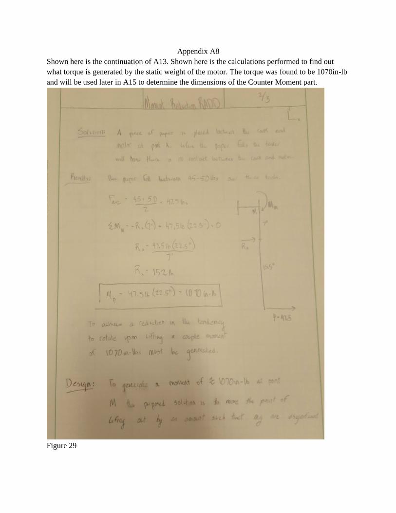
Appendix A8
Shown here is the continuation of A13. Shown here is the calculations performed to find out
what torque is generated by the static weight of the motor. The torque was found to be 1070in-lb
and will be used later in A15 to determine the dimensions of the Counter Moment part.
Figure 29

Appendix A9
Shown here is the analysis of the torque generated by the static weight of the motor. The torque
generated by the counter moment part will have to be equal to the torque generated by the static
weight of the motor in order to cancel it out and lift the motor vertically. Thus, the 1070in-lb was
set equal to the weight of the motor divided by two (the counter moment lifts from two points)
and multiplied by the length of the counter moment-moment arm (x) and multiplied by 2
because, again the motor is lifted by two points. This equation resulted in the counter moment-
moment arm being approximately 9.2 inches away from the point x labeled on the Motor Clamp
below.
Figure 30

Appendix A10
Shown here is the analysis of a potential worst case scenario in which the user lets go of the hand
crank when the motor is being lifted. The worst case scenario is defined as a quarter rotation
(pi/2) of motion before the dog and pawl system stops the rotation. As can be seen in the
calculations the force exerted onto the mating surfaces of the dog and pawl are less than their
yield strength and thus the parts will withstand the forces.
Figure 31

Appendix A11
Shown below is the design of the standard pin throughout the design. The diameter was chosen
for simplicity in manufacture and comparability to what can be found at a local store. As can be
seen at the bottom, manufacturing the pins is significantly cheaper than purchasing similar
products at a local store. Local store: Ranch & Home.
Figure 32

Appendix A12
Shown below is the analysis of the forces exerted on the dog of the dog and pawl system as was
calculated in A9. The weakest point of this system is the pin that holds the dog in place. As the
dog is a small part the pin must also be reduced in size calling for a pin diameter of .25 inches.
With a deflection of 2 thousandths of an inch this design can be kept.
Figure 33

Appendix A13
Shown below is the analysis of the stress and deflection of the lifting axle under load. The
calculations show that the axle will experience .3 thousandths of an inch of deflection under
loading. For simplicity the load was assumed to be in the center, using this equation furthers the
safety of the device in that it assumes a more concentrated load. The load in reality will be at two
indiscriminate points near points Rp and Rs.
Figure 34

Appendix A14
Shown here is the analysis of the final design of the lifting arms and motor clamp plate. The
requirement is that the motor be lifted at least to the height at which the motor clamp plate
receiver can mate with the extended base plate bar.
Figure 35

Appendix A15
This calculation and A16 show the difference in the forces required to rotate the lifting axle
under loading. As was noted in the Analysis Section 4, the friction generated by the roughness of
the shaft and its respective holes and out of round nature of the shaft would require the user to
generate more than 38lbs of force to rotate the shaft. As a result the designer purchased two oil
impregnated bronze bushings. With the new design the rotation of the shaft under loading
required significantly less force than before.

Appendix A16
As noted above the installation of the bronze bushings significantly reduces the forces needed to
rotate the shaft and list the motor. The difference between using 25lbs of force and 64lbs of force
to rotate the shaft is worth the extra time and money spent on implementing the design changes.

Appendix A17
Shown below is the analysis of the lifting arm seats pin. This pin is subjected to the greatest
shear forces in the design and results in a shear of 2040psi. This is acceptable because it does not
approach the yield strength of the material.

Appendix A18
Shown below is the redesign of the lifting axle. It was necessary to redesign the axle because the
dog and pawl system has to be welded onto it for the system to work. A weld on a shaft as
hollow as the one noted in appendix A13 would warp and not allow for easy rotation or reliable
stopping power if the dog and pawl system were needed to prevent sudden dropping of the load.

Section 11: Appendix B Drawings
Appendix B1
Shown here is the top view of the swim platform. This drawing illustrates the dimensional
constrictions of the motor head and the swim platform. The requirements state that the motor
must not interfere with the swim platform at any stage of the installation or use of the motor. As
a result the motor mount must hold out the motor in a cantilever type fashion.
Figure 37

Appendix B2
Shown here is the drawing B2, this part is welded onto the mount insert plate and transfers the
torque generated by the counter moment to the motor.
Figure 39

Appendix B3
Shown here is the drawing of the Counter Moment design. This part is used so that the motor can
be lifted at a specified angle relative to the swim platform. Without this part, the lifting would be
useless as the orientation of the motor wouldn’t allow for easy installation.
Figure 40

Appendix B4
Shown here is the drawing file of the 3x.375’’ pin. This pin is used in the assembly of the
removable lifting apparatus pieces and throughout the assembly for mating parts.
Figure 41

Appendix B5
Shown here is the drawing file of the motor receiver. This piece has an adjustable insert that will
be affixed by the 2.5x.5 pin. The adjustment allows for the motor to be lowered onto the receiver
plate and then be pushed back to the desired extension.
Figure 42

Appendix B6
Shown here is the base plate on which the whole motor will be affixed. The holes are matched
drilled from the holes that already exist on the motor clamp. 5/16” bolts will be used to fasten the
two parts together. This part will transfer the torque generated by the counter moment arms to
the motor and will result in parallel lifting.
Figure 43

Appendix B7
Shown here are the extension arm seats. This part serves to support the extension arms when
they are installed. By using congruent dimensions the seat will accept the extension arm being
inserted into it. The parts will be fastened together via pin connection.
Figure 44

Appendix B8
Shown here is the Jig designed to ease the drilling of the .056” pin hole found in the pin in
Appendix B11. This Jig serves to reliably make cotter pin holes on the rounded surface of the
manufactured pins.
Figure 45

Appendix B9
Shown here is the permanent fixture that will be bolted to the motor clamp via its own bolts. This
part serves to transfer the weight of the motor to the counter moment arms through the counter
moment pegs in order to lift the motor at an appropriate angle.
Figure 46

Appendix B10
Shown here is the drawing for the pawl. This part will act as both a safety restraint as well as a
holding device for the user if the installation needs to be paused at any moment. It works as any
dog and pawl system will work and only allows the axle to turn one way which is decided by the
user.
Figure 47

Appendix B11
Shown here is the Dog part of the dog and pawl system. This part will act as the stopping
mechanism that the pawl will rotate about.
Figure 48

Appendix B12
Shown here is the lifting axle. This part will serve as both the spool and the vertical support of
the lifting mechanism. See assembly for views of how the dog and pawl system will function
when attached to the axle. The hole will be where the hand crank inserts and transfers torque, see
B15.
Figure 49

Appendix B13
Shown here is the drawing for the hand crank. This part will be used by the user to transmit a
torque through the lifting axle in order to lift the motor. It will slide into the hole on the lifting
axle and be pinned with a cotter pin.
Figure 50

Appendix B14
Shown here is the alignment bracket designed and constructed during the week of 3/01/18. It’s
purpose is to maintain the alignment of the lifting arm holes to the lifting axle. It is vital for easy
installation and use of the device.
Figure 51

Appendix B15
Shown here is the bushing purchased from Mcmaster Carr on 2/28/18. This part serves to reduce
the friction of the rough surfaces of the holes on the lifting arms and the rough surface of the
lifting axle.
Figure 52

Appendix B16
Shown here is the assembly drawing, part names, and notes for manufacture.
Figure 53


Appendix B16 Cont.
Figure 54

Section 12: Appendix C Parts List Appendix C1
Part Material Dimensions Metals Depot
Price B (CWU
Burvee) Actual
Base Plate
https://www.metalsdepot.co
m/steel-products/steel-plate
Stainless
Steel .25x24x24’’ $79.64 $50.00 $50.00
¼” Rectangular Tubing
https://www.metalsdepot.co
m/steel-products/steel-
square-tube
Stainless
Steel 8’x1.5’’x1.5’’ $76.50 $125.49 $76.50
Pulley Wheel N/A 2(4’’Diameter) $4.00 $3.05 $3.05
Pin
https://www.metalsdepot.co
m/steel-products/steel-
round-bar?product=1103
Stainless
Steel 2(.5’’x4.5’’) $4.84 $2.99 $2.99
Pin
Stainless
Steel 3/16’’x7½’’ $2.00 $2.65 $2.00
¼’’ Rectangular Tubing
https://www.metalsdepot.co
m/steel-products/steel-
square-tube
Stainless
Steel 2’’x2’’x2’ $21.54 $50.54 $21.54
Welding Materials TBD
1” Square Bar
https://www.metalsdepot.co
m/steel-products/steel-
square-bar Steel 1”x1”x24” $11.16 $11.16
Axle
https://www.metalsdepot.co
m/steel-products/steel-
round-bar Steel 9”x.5” Round Bar $2.92 $2.92
Shipping $78.42
Labor Rate Total Hours Cost
Student Hours $1.25/hr $150.00 $187.50
Contracted Hours $15.00/hr $5.00 $75.00

Total Cost $516.22
Receipts
ORDER # 9274630 Thursday 12/28/2017 12:59 PM
Customer ID: N/A
Payment Type: Visa
Order PO Number:
Shipping Method: UPS Ground
Address Type: Residential
Tracking Number:: N/A

Appendix C2
ORDER DETAILS
# Item Description Qty Size Price Total
1. R112 1/2 inch Dia. Hot Rolled A-36
Steel Round
1
4' $4.84 $4.84
2. P114 1/4 inch THICK A36 Steel
Plate
1
2' x 2' $56.04 $56.04
3. T111225
0
1-1/2 X 1-1/2 X 1/4 wall
A500 Square Steel Tube
1
8' $71.00 $71.00
4. T122250 2 X 2 X 1/4 wall A500 Square
Steel Tube
1
2' $21.54 $21.54
5. SQ11 1" x 1" Hot Rolled A-36 Steel
Square
2
2' $10.94 $21.88
Order Comments / Delivery Instructions: Sub-Total: $175.30
Shipping: $78.42
Sales Tax: $0.00

Customer accepted and agreed to Terms & Conditions of Sale. Order
Total:
$253.72
Shown above is the receipt from Metals Depot’s first order for the project. The parts included are
the extension arms, base plate, pins, and motor seat arm.

Appendix C3
ORDER # 9277329 Shipped on Friday 01/26/18 12:00 AM
Customer ID: N/A
Payment Type: Visa
Order PO Number:
Shipping Method: UPS
Address Type: Residential
Tracking Numbers:
HYPERLINK
"http://www.metalsdepot.com/catalog/order-
tracking/9277329" 1Z29E9W90347008066
1Z29E9W90348756470
ORDER DETAILS
# Item Description Qty Size Price Total
1. R11 1 inch Dia. Hot Rolled A-
36 Steel Round
1
4' $19.00 $19.00
2. T1112250 1-1/2 X 1-1/2 X 1/4 wall
A500 Square Steel Tube
1
8' $71.00 $71.00
3. P114 1/4 inch THICK A36
Steel Plate
1
1' x 2' $30.52 $30.52
Order Comments / Delivery Instructions: Sub-
Total:
$120.52
Shipping: $74.37
Sales
Tax:
$0.00
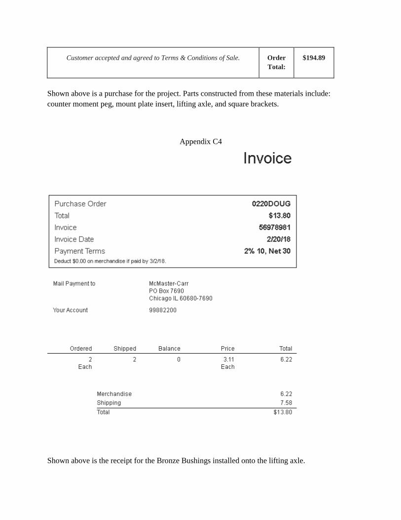
Customer accepted and agreed to Terms & Conditions of Sale. Order
Total:
$194.89
Shown above is a purchase for the project. Parts constructed from these materials include:
counter moment peg, mount plate insert, lifting axle, and square brackets.
Appendix C4
Shown above is the receipt for the Bronze Bushings installed onto the lifting axle.

Section 13: Appendix D Budget
Appendix D1
Shown here is the list of parts required for the assembly of the project. The prices of the
components do not vary wildly across the market as they are mostly standard parts like tubing
and plates and pins. As can be seen in the assembly below there are 4 half inch by 4.5 inch pins.
As measured the length of square tubing on SolidWorks requires 7.83 feet. For sake of making
unforeseen mistakes the designer will order 8.5 feet. The base plate will have to be bought in
standard dimensions and then machined to the specifications of the project. The standard size
that is closest to the dimensions in the design is the 24 inch square plate. The pulley wheel is sold
by McMaster-Carr and comes in the standard size of .5’’x4’’. The pulley will serve to redirect
the forces of the hand crank. The hand crank is also sold on McMaster-Carr and will suffice for
the 38 pound force requirement as it creates a moment large enough around its axis that ten
pounds of force will lift the motor. All parts ordered from McMaster-Carr have a hyperlink to
their website for easy citation. All other pricing was gathered via phone call with the suppliers.
The total cost after accounting for man hours provided by the welder and the designer is at
$516.22 before tax. This is not within the spending limit set by the customer and will require
some out of pocket expense from the designer or other interested parties.
Parts List:
# Part Material Dimensions
1 Base Plate Stainless Steel .25x24x24’’
2 ¼” Rectangular Tubing Stainless Steel 12’x1.5’’x1.5’’
3 Pulley Wheel N/A 2(4’’Diameter)
4 Pin Stainless Steel 2(.5’’x4.5’’)
5 Pin Stainless Steel .5’’x7.5’’
6 Motor Seat Axle Stainless Steel 9’’x.5’’
7 Motor Seat Slide Stainless 1’’ Square Bar
8 Counter Moment Stainless 4’x1.5” Round Tubing
9 ¼” Tubing Stainless 12”x2’’

Section 14: Appendix E Schedule
Estimated Project Duration:
92 Hours
Actual Project Duration to 6/1/18:
142 Hours
Schedule:
Quarterly schedules provided below. Milestones are marked with the blue triangles and task
dates are marked with the green cells. Quarterly duration estimates are provided at the bottoms
and the actual durations will be fulfilled as the quarter’s progress. For direct access to the
spreadsheet use the hyperlink provided below.
Hyperlink to fully detailed Gantt Schedule.
Figure 55
Figure 56

Figure 57
Figure 58

Figure 59
Figure 60
Total Project Duration: 142 Hours

Section 15: Appendix F - Expertise and Resources
● Capovilla, Dennis.
● Johnson, Craig.
● Mott, Robert L., Machine Elements in Mechanical Design. 5th Edition.
● Pringle, Charles.
● Burvee, Matt
● Stockman, Nolan
● Bramble, Tedman
● Metals Depot [email protected] https://www.metalsdepot.com/catalog/cart

Section 16: Appendix G –Testing Data
Test 1 Results:
Part Deflection under Loading
(thousandths of an inch)
Predicted Deflection Under
Loading (see Calculations)
Portside Lifting Arm 59, 62, 62
Ave=61
44.04
Starboard Side Lifting Arm 59, 62, 62
Ave=61
33.85
Telescoping Receiver Arm 21, 21, 22
Ave=21.3
15.77
Test 2 Results:
Trial 1:
Installer Name Installation Time (Mins)
Doug (Designer) 25
Larry (Customer) 28
Optimizations:
More slack in hanging ropes, this allows the user to install the counter moment arms much more
easily.
Trial 2:
Installer Name Installation Time (Mins)
Doug (Designer) 20
Larry (Customer) 18
Optimizations:
Use a ladder to ease hand crank rotation. The top of the cranking is about 8 feet above the ground
because the swim platform is about 5 feet tall, the lifting arms are 20 inches tall and the hand
crank adds another 14 inches.
Trial 3:

Installer Name Installation Time (Mins)
Doug (Designer) 12
Larry (Customer) 13
Optimizations:
None.
Test 3 Results:
Position Force Force Force Force Force Force Force Force Force Force
0° 27 29 29 31 26 31 29 29 29 30
90° 27 27 28 28 26 26 27 29 25 25
180° 27 27 29 29 30 31 33 32 27 27
270° 29 29 28 30 26 25 30 29 28 27
Average force used to lift motor:____28.2________lbs
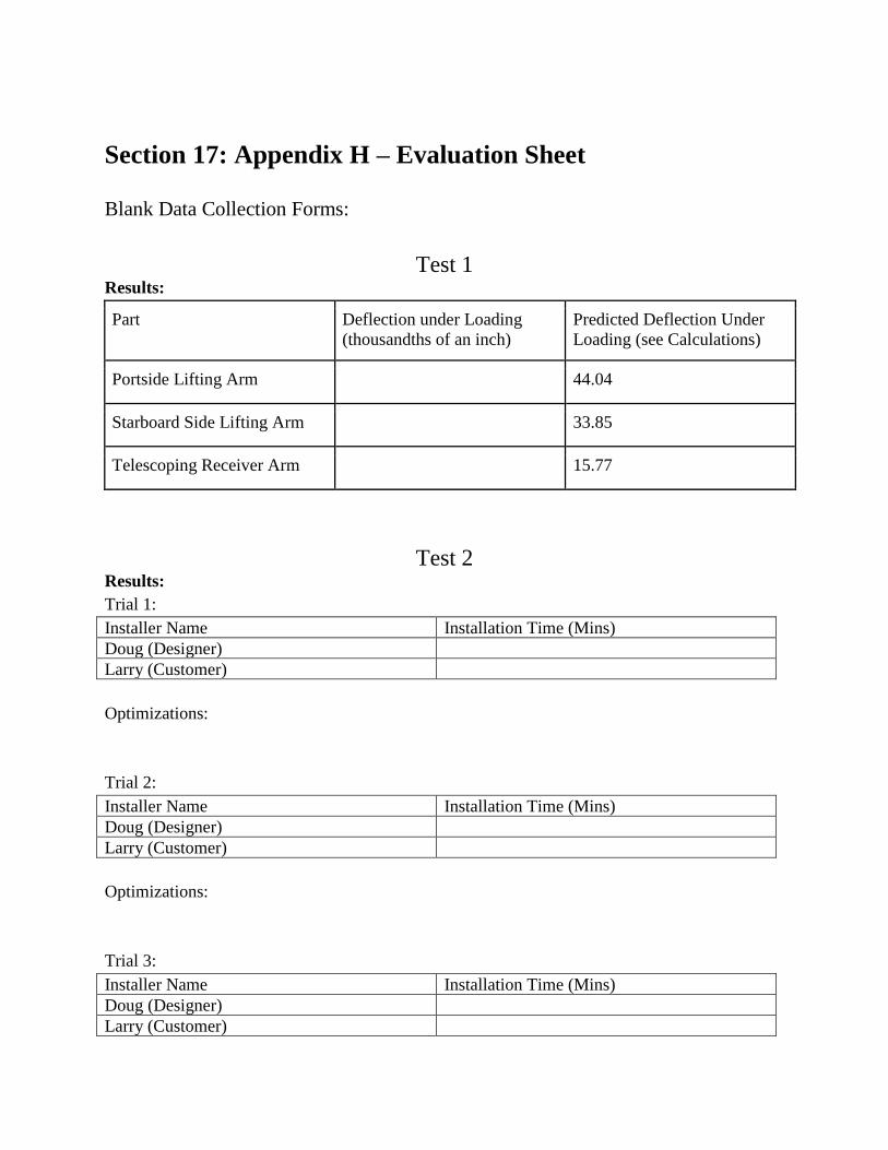
Section 17: Appendix H – Evaluation Sheet
Blank Data Collection Forms:
Test 1 Results:
Part Deflection under Loading
(thousandths of an inch)
Predicted Deflection Under
Loading (see Calculations)
Portside Lifting Arm 44.04
Starboard Side Lifting Arm 33.85
Telescoping Receiver Arm 15.77
Test 2 Results:
Trial 1:
Installer Name Installation Time (Mins)
Doug (Designer)
Larry (Customer)
Optimizations:
Trial 2:
Installer Name Installation Time (Mins)
Doug (Designer)
Larry (Customer)
Optimizations:
Trial 3:
Installer Name Installation Time (Mins)
Doug (Designer)
Larry (Customer)

Optimizations:
Test 3 Results:
Position Force Force Force Force Force Force Force Force Force Force
0°
90°
180°
270°
Average force used to lift motor:____ lbs
Section 18: Appendix I – Testing Report
Test 1 Summary:
The purpose of this test is to compare the calculated deflection values for each load bearing part
to the actual deflection of the parts. As noted in the requirements sections of the Engineering
Report no part shall deflect more than 3/8ths of an inch or .375 inches. The designs will be
acceptable if they meet this requirement. If the part fails to meet the requirement but does not
permanently deflect the part design will still be considered a successful design. Permanent
deformation will require redesign.
Time:
Conduct the test during the week of 4/9/18.
Duration:
The test should consume no more than 3 hours.
Place:
CWU Machine Shop Room 107
Risks:
Take care not to damage the knee of the Partner Mill while clamping and loading the test
equipment. Wear safety goggles while in the machine shop.
Resources:
1. Magnetized Long Arm Adjustable Dial Indicator
2. Rigid Table (Horizontal Mill Knee)
3. Granite Flat Table
4. T nuts (2)
5. Tightening Nuts (2)
6. Wheeled Hydraulic Lift Cart (weight transport and relief)
7. Clamping Bracket
8. 230lbs of weight (Tensile Testing Weights Rm. 127)
9. Hanging rope and weight holder
10. Loaded Apparatus Parts
Procedures:
Lifting Arms

1. Secure the part to a flat and rigid table with clamp and nuts so that the load can be place
18inches from the edge of the table.
2. Set up a dial indicator on the same level as the support on the granite table, ensure it is
magnetized and secure.
3. Touch the dial onto the test piece as close to the loading point as possible and zero it.
4. Secure the weight holder to the part with the rope and its hook.
5. Load the weight holder with the test weights while the table holds all weight.
6. Apply the load = 225lbs to the point of loading on the test piece by relieving the lifting
table (pull the release handle).
7. Record the deflection of the piece by recording the reading on the dial indicator.
8. Pump lift table until the weights are not loaded onto the part.
9. Repeat the test for each lifting arm.
Notes:
The starboard side lifting arm is the shorter of the two arms. See figure 1
Telescoping Receiver Arm
1. Secure the part to a flat and rigid table with clamp and nuts so that the load can be
8inches from the edge of the table.
2. Set up a dial indicator on the same level as the support on the granite table, ensure it is
magnetized and secure.
3. Touch the dial onto the test piece as close to the loading point as possible and zero it.
4. Secure the weight holder to the part with the rope and its hook.
5. Load the weight holder with the test weights while the table holds all weight.
6. Apply the load = 225lbs to the point of loading on the test piece by relieving the lifting
table (pull the release handle).
7. Record the deflection of the piece by recording the reading on the dial indicator.
8. Pump lift table until the weights are not loaded onto the part.
9. Repeat the test for each lifting arm.
Notes:
Results:
Part Deflection under Loading
(thousandths of an inch)
Predicted Deflection Under
Loading (see Calculations)
Portside Lifting Arm 59, 62, 62
Ave=61
44.04
Starboard Side Lifting Arm 59, 62, 62
Ave=61
33.85
Telescoping Receiver Arm 21, 21, 22
Ave=21.3
15.77

Discussion:
Shown in Appendix A3, A4, and A5 of the Engineering Report the deflection of these loaded
parts was, in order of the results, .0440inches, .0440inches, and .01577inches. It is worth noting
that the tested parts exceeded the calculated deflections by approximately 25% consistently. This
error can be accounted for in several areas, but it is most likely that the error is caused by the
roughness of the moment of inertia calculations for each part. A Finite Element Analysis would
be required to have a moment of inertia more reflective of reality. No part deflected more the
.375inches. No part was deflected to the point of permanent deformation and as per the
requirements of this project all parts are therefore successful in design.
Conclusion:
The designs of the loaded parts have resulted in an overall success as per the requirements of the
project. No part deflected to the point of permanent deformation or the maximum proposed point
of .375inches and as a result the requirement of safety and durability noted in the Engineering
Report has been met.

Test 2
Summary:
The scope of this test is to determine if the design of the device allows for the user to install their
outboard motor in a timely manner. As noted in the requirements sections of the Engineering
Report, the installation of the motor shall not exceed 30 minutes. This timeframe includes
mounting the counter moment arms, inserting the lifting arms with the axle in its holes, rotating
the shaft to lift the motor, inserting the receiver bar into the mount plate, and sliding the motor
and receiver bar to the desired distance from the swim platform. The success of the design will
depend on the 30 minute mark not being exceeded. If the user fails to install the motor within
that time frame the test will be determined to be a failure. Secondary goals to be observed in this
test are: safety of the device (does the user feel financially and physically secure), and ease of
lifting (does the shaft rotate easily/with less force than a third of the weight of the motor).
Time:
Conduct test during the week of 4/16/18.
Duration:
The test should consume no more than 5 hours.
Place:
Residence of the customer and his boat and motor.
Risks:
The user and customer should take care not to be directly underneath any hanging loads or
unsupported device parts.
Resources:
1. Timer
2. Test motor (20HP)
3. Design Device
Procedure:
1. Assure that the motor mount base plate is securely fastened to the swim platform of the
boat.
2. Locate the outboard motor below the swim platform by wheeling it out on its storage
rack.
3. Locate the device and its removable components within reach of the swim platform and
motor.
4. Start the timer
5. Insert the lifting arms into the arm receivers on the base plate.
6. Insert the pins into the lifting arm receivers so that the pin heads are facing outward and
install their cotter pins.
7. Install the counter moment arms onto the counter moment pegs of the mount plate.
8. Pin the counter moment arms into place so that the pin heads are up.

9. Install cotter pins into counter moment pins.
10. Rotate the hand crank and proceed to lift the motor to the point where the mount plate
receiver tube is aligned with the receiver arm on the base plate.
11. Insert the receiver arm into the mount plate and pin the two parts together.
12. Install the cotter pin in the receiver tube on the mount plate.
13. Remove the tension in the lifting ropes and remove the counter moment arms.
14. Slide the motor and receiver bar to the desired distance from the swim platform.
15. Remove the lifting arms from the base plate.
16. Stop the timer.
Notes:
Be sure to never be underneath any of the loaded or pinned parts during any point of the
installation. Take notes of the installation process and attempt to find process flaws. Note these
flaws and determine ways to optimize the procedure. Implement these optimizations in the
following trial. Perform three trials and analyze the resulting time differences.
Results:
Trial 1:
Installer Name Installation Time (Mins)
Doug (Designer) 25
Larry (Customer) 28
Optimizations:
More slack in hanging ropes, this allows the user to install the counter moment arms much more
easily.
Trial 2:
Installer Name Installation Time (Mins)
Doug (Designer) 20
Larry (Customer) 18
Optimizations:
Use a ladder to ease hand crank rotation. The top of the cranking is about 8 feet above the ground
because the swim platform is about 5 feet tall, the lifting arms are 20 inches tall and the hand
crank adds another 14 inches.
Trial 3:
Installer Name Installation Time (Mins)
Doug (Designer) 12
Larry (Customer) 13
Optimizations:

None.
Discussion:
The installation of the motor never took more than 30 minutes which would indicate a success
for the design. The optimizations, paired with the practice of uninstalling and reinstalling several
times lead to a reduced installation time overall. As shown in the data the time difference
between the designer and customer is rather negligible and both of their install times reduced
significantly. The counter moment design was not successful. The motor would not remain level
with the swim platform and this is likely due to the roughness of the calculations to determine
the moment needed to balance it. A solution has been devised and will be implemented as the
quarter progresses. Because of the counter moment not working properly, the design required to
users to install the motor. One to balance the motor and the other to rotate the hand crank. With
the redesign in progress it is likely that this problem will be resolved. During the first installation
of the motor the lifting rope knot came undone on the starboard side of the apparatus, luckily the
portside hanging rope remained intact and neither the motor nor the user were damaged. After
tying a new knot, the lifting ropes performed effectively for the next six trials. Secondary goals
were met, the customer verbally indicated satisfaction in both the design safety and efficacy.
Rotating the hand crank seemed to require less than 38lbs of force (1/3 the weight of the motor)
but testing in the future will determine if this observation is valid. It was noted that this design,
though useful, would be more apt in installing a larger outboard motor, one in which no two
average boaters would be able to lift (200lbs +).
Conclusion:
Overall the design has effectively gone from concept to reality. With a few incumbent
modifications, this outboard motor installer is a useful and practical tool for the average boater.
As shown in the video on the website, the installation of the motor takes an incredible 7 minutes.
The expectations for the design have not only been met but exceeded.

Test 3 Summary:
The testing of the third requirement will require the mount to be fully constructed. This test will
use the hand crank of the lifting mechanism. The cranking of the hand crank will require the user
to apply a force to the handle. The force will not exceed 38 pounds of force when rotating the
handle. Another aspect of the 38 pound force limit will be in the setup of the motor install
apparatus. The removable pieces should not weigh more than 38 pounds each. As noted in
Appendix A15-16 the force required to rotate the lifting shaft is calculated to be approximately
25lbs. If this calculation is accurate then this portion of the project requirements will be a
success. This test will require a fish scale, a spring-loaded scale to measure the force required to
rotate the hand crank. The scale will be affixed to the handle of the hand crank most
representative of where a user would place their hand. Data will be recorded at four locations and
averaged, the four points are located at 0, 90, 180, and 270 degrees from normal +/- 15 degrees.
The motor will have to be lifted completely off the ground and hanging by the lifting ropes
attached to the lifting axle for each position. Measurements shall be taken throughout the entire
lifting distance spanning 36 inches and requiring 11 full rotations; 44 data points will be taken
and averaged to provide a relatively accurate assessment of force. Data will be presented below
in the results subsection of Testing & Analysis.
Time:
Conduct test during the weekend of 5/6/18.
Duration:
The test should consume no more than 3 hours.
Place:
Residence of the customer and his boat and motor.
Risks:
The user and customer should take care not to be directly underneath any hanging loads or
unsupported device parts. The spring scale should be securely and safely attached to the hand
crank.
Resources:
1. Spring Scale
2. Test motor (20HP)
3. Design Device
Procedure:
1. All pieces to the removable lifting mechanism will be weighed. Volumetric mass
measurements performed on SolidWorks may also provide these data.

2. To test whether the hand crank will require more than 38 pounds of force the motor must
be ready to be lifted by the mechanism. The 38 pounds of force must be sufficient to
move the motor any distance. This test does not require the motor to be accelerated at a
rate that would require a torque greater than what 38 pounds of force could create.
3. The user will set up the hand crank so that it is horizontal.
4. The user will apply a load downward (to lift the motor) with an attached spring scale to
the handle of the hand crank handle.
5. Record the reading of the scale.
6. Rotate the shaft 90 degrees to lift the motor.
7. Stop at 90° from normal and record the force at that position.
8. Rotate the shaft to 180° from normal and record the force at that position.
9. Rotate the shaft to 270° from normal and record the force at that position.
10. Rotate the shaft to the starting position at 0° and record the force.
11. Lift the motor completely to its installation position recording the force at each of the
four positions: 0°, 90°, 180°, and 270° at each passing.
12. Average the results.
Notes: ensure that the dog and pawl safety catch is not taking on any loading while recording the
data at the various points.
Results:
Position Force Force Force Force Force Force Force Force Force Force
0° 27 29 29 31 26 31 29 29 29 30
90° 27 27 28 28 26 26 27 29 25 25
180° 27 27 29 29 30 31 33 32 27 27
270° 29 29 28 30 26 25 30 29 28 27
Average force used to lift motor:____28.2________lbs
Discussion:
The predicted values for the third test were accurate to the actual values. With an error of
approximately 13% the design was successful. The hand crank force never exceeded 38lbs while
lifting the motor onto the boat. The error in calculation is likely due to the poor fit of the bronze
bushing into its hole. The portside bushing was a tight fit and this restricted it’s rotation on its
ID. Rotation is preferred in the ID of the bushing because the shaft is polished and smoother
there. The tightness of the fit caused the bushing to rotate inside the lifting arm hole rather than
the shaft to rotate in the bushing. Removal of the bushing and re-polishing the shaft is possible
and the fit requirements will be stricter in the next manufacture process.

Conclusion:
The design of the lifting arms and axle were a success. Although the predicted values were again
a little short like the deflection tests, the requirement was never exceeded. The lifting/rotating
force remained under the maximum force limit of 38lbs and thus the design was a success.

Section 19: Appendix J – Resume/Vita
DOUGLAS J. DUNBAR
2125 East Mount Daniels Dr.
Ellensburg, WA 98926
Phone: 1-509-859-6449
Email: [email protected]
EDUCATION
◆ High school diploma from Sequim High School, Sequim, Washington (2013)
◆ Enrolled in Mechanical Engineering Technology Program, Central Washington University, Ellensburg,
Washington (will graduate in June, 2018).
◆ American Red Cross Certifications:
• First Aid Expires: 03.27.19
• CPR/AED use for the Professional Rescuer Expires 03.27.19
• Lifeguard/Professional Rescuer and Lifeguard Instructor Expires 01.01.19
WORK EXPERIENCE (PART TIME)
Aquatic Maintenance Lead (August, 2017 - Present) at Kittitas Valley Memorial Pool, Ellensburg,
Washington
Responsibilities:
● Monitor & maintain the pool pumps, gauges, boilers, and drainage systems
● Inform my superiors of potential or current mechanical problems with pool equipment
● Perform weekly water/filter changes for the hot tub
● Adjust chemical makeup of pool or hot tub water if the chemicals are out of spec.
● Account for daily monies and fill out a transmittal for the City of Ellensburg
● Deliver daily monies to City Hall
● Record employee weekly hour accumulations and correct if necessary
● Complete Aquatic Facility Operator (AFO) Course by May, 2018
Lifeguard and Staff Trainer (June, 2013 – August, 2017) at Kittitas Valley Memorial Pool, Ellensburg,
Washington Responsibilities:
• Monitor and adjust pool equipment, pumps, piping, heating and chemistry
• Maintain a clean and safe environment for patrons
• Conduct lifeguard/staff meetings and training sessions
• Conduct random lifeguard emergency drills and evaluate performances
• Monitor and update lifeguards on rescue skills, CPR, AED and first aid use
• Supervise and communicate patron & lifeguard rules for two pools, a hot tub and a sauna
• Teach American Red Cross Lifeguarding Courses
• Interview Lifeguard Applicants regarding lifeguarding, lifesaving skills, work experience, and personality
• Evaluate applicants’ performance and provide a report to my supervisor
• Account for daily monies and fill out a transmittal for the City of Ellensburg
• Deliver daily monies to City Hall
• Record employee weekly hour accumulations and correct if necessary

Lifeguard (June, 2009 – May, 2013) at Sequim Aquatic Recreation Center, Sequim, Washington Responsibilities: Supervise and communicate rules for patrons using two pools, two saunas, a rope swing, waterslide, and a
hot tub,
and respond appropriately in emergency situations.
OTHER SKILLS AND EXPERIENCES ◆ Able to communicate in Spanish (4 years HS) and American Sign Language (1 year CWU)
◆ Awarded Eagle Scout rank by the Boy Scouts of America
◆ High school activities:
• Honor Society
• Soccer team (Captain)
• ASB Leadership Team
• Swimming team (Varsity Captain)
REFERENCES
BRIAN JONES, Mechanical Engineer Boeing Aerospace Company
3003 W Casino Road
Everett, WA 98208
Phone: 425 234 8609
Email: [email protected]
LEE DUNBAR (Uncle), Former Vice President and Software Engineer. Currently, a Technical Fellow. FUJIFILM SonoSite, Inc
4102 Tamarack Bay Road
Loon Lake, WA 99148
Phone: 206 972 9718
Email: [email protected]
ALEISHA HALEY (Cousin), Senior Verification Engineer FUJIFILM SonoSite, Inc
22011 30th Dr. S.E.
Bothell, WA 98021
Work: 435 951 1200
Email: [email protected]
JODI HOCTOR, Aquatic and Recreation Supervisor Kittitas Valley Memorial Pool
815 E Sixth Ave
Ellensburg, WA 98926
Work: 509 962 7210
Email: [email protected]
DIANE STARKWEATHER, Secretary Kittitas Valley Memorial Pool
815 E Sixth Ave
Ellensburg, WA 98926
Work: 509 962 7210 (available M-R 8 AM-3:30 PM)
AUSTIN LAW, Chemical Engineer Janicki Bioenergies
Seattle, WA 98105
Personal: 360 797 4735
Email: [email protected]
