eaton duraforce™ hmr conversion procedurespub/@eaton/@hyd/documents/c… · eaton duraforce hmr...
TRANSCRIPT

Eaton® DuraForce™ HMR Conversion Procedures
2 EATON Duraforce HMR Conversion Procedures Manual E-MOPI-TM005-E July 2012
Content Page #
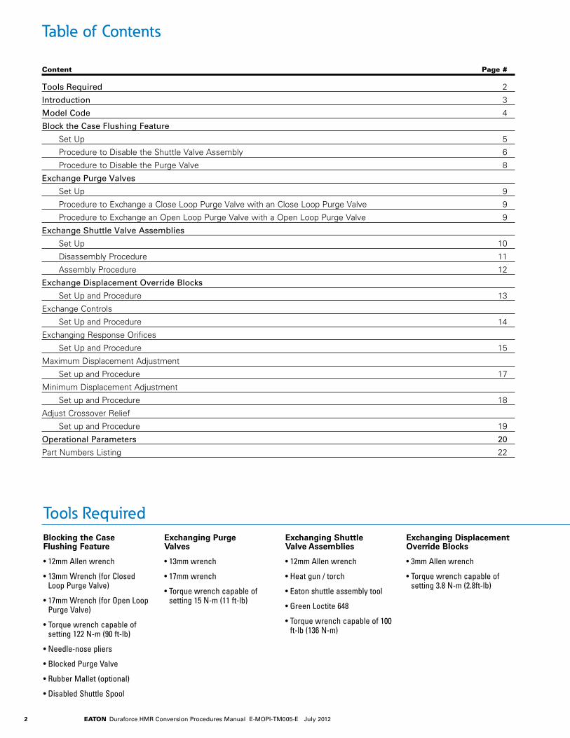
Table of Contents
Tools Required 2
Introduction 3
Model Code 4
Block the Case Flushing Feature
Set Up 5
Procedure to Disable the Shuttle Valve Assembly 6
Procedure to Disable the Purge Valve 8
Exchange Purge Valves
Set Up 9
Procedure to Exchange a Close Loop Purge Valve with an Close Loop Purge Valve 9
Procedure to Exchange an Open Loop Purge Valve with a Open Loop Purge Valve 9
Exchange Shuttle Valve Assemblies
Set Up 10
Disassembly Procedure 11
Assembly Procedure 12
Exchange Displacement Override Blocks
Set Up and Procedure 13
Exchange Controls
Set Up and Procedure 14
Exchanging Response Orifices
Set Up and Procedure 15
Maximum Displacement Adjustment
Set up and Procedure 17
Minimum Displacement Adjustment
Set up and Procedure 18
Adjust Crossover Relief
Set up and Procedure 19
Operational Parameters 20
Part Numbers Listing 22
Blocking the Case Flushing Feature
• 12mm Allen wrench
• 13mm Wrench (for Closed Loop Purge Valve)
• 17mm Wrench (for Open Loop Purge Valve)
• Torque wrench capable of setting 122 N-m (90 ft-lb)
• Needle-nose pliers
• Blocked Purge Valve
• Rubber Mallet (optional)
• Disabled Shuttle Spool
Exchanging Purge Valves
• 13mm wrench
• 17mm wrench
• Torque wrench capable of setting 15 N-m (11 ft-lb)
Exchanging Shuttle Valve Assemblies
• 12mm Allen wrench
• Heat gun / torch
• Eaton shuttle assembly tool
• Green Loctite 648
• Torque wrench capable of 100 ft-lb (136 N-m)
Exchanging Displacement Override Blocks
• 3mm Allen wrench
• Torque wrench capable of setting 3.8 N-m (2.8ft-lb)
Tools Required

3EATON Duraforce HMR Conversion Procedures Manual E-MOPI-TM005-E July 2012
This manual will provide you with information and procedures for general conversions of Eaton® DuraForce™ HMR Regulated Variable Displacement Open and Closed Loop Hydraulic Motors. Procedures outlined in this manual will allow you to be more flexible with your inventory and better service your customers. To ensure accuracy of conversion and prevent part loss or damage, certain components or subassemblies are disassembled, inspected, and reassembled when removed from the motor.
Training
You have been provided information on the conversion of DuraForce products. Proper application of the information requires specific training and may require use of specialized tooling and equipment. All requests for training must be coordinated through your Eaton Account Manager. He can also provide you price and availability of any specialized tooling. If you choose to proceed with the conversion of the DuraForce products absent the necessary training and/or these specialized tools, you do so at your risk.
Eaton will accept no claim for warranty resulting from deficiencies in the conversion. Please refer to the Eaton literature web site for warranty information at www.eaton.com/hydraulics/warranty.
Labeling Converted Units
All units that have been converted must retain the original Eaton label and have a second Eaton label placed on the unit. This second label at a minimum must state
Converted Eaton Model Code # (Final Eaton model code of the converted unit)
Conversion done by (Name of your company)
Conversion Parts
All requests for specific conversion part information should be addressed to your Eaton account representative. Additional information can be found through your Eaton customer connect portal. All requests or inquiries must be accompanied by the complete model and serial number of the base unit you want to convert.
Cleanliness
Cleanliness is extremely important when repairing a hydrostatic pump or motor. Before disconnecting the lines, clean foreign material from exterior of unit. Work in a clean area. Clean all metal parts in clean solvent. Blow parts dry with air. Don’t wipe parts with cloth or paper towel, because lint or other matter could cause damage. Check all mating surfaces. Replace any parts that have scratches or burrs that could cause leakage. Don’t use coarse grit paper, files or grinders on parts.
Environmental Concerns
Protection of the natural fundamentals of life is one of our predominant tasks. We are continuously improving the protection of the environment as far as applications are concerned. We encourage you to contribute your share to comply with this demand. In connection with work to be performed, the environmental regulations of the machine manufacturer must be respected.
In general:
• Greases and oils which cannot be used any more have to be collected. They are normally a threat to water reserves and must be kept away from the environment.
• Adhere to national and local regulations for waste disposal.
Seals
A good conversion policy is to replace all old seals with new seals whenever units are disassembled. This avoids potential damage during seal removal. Lubricate seals with petroleum jelly. Use only clean and recommended oil when assembling unit. Information on recommended filters and fluids can be found in the Operational Parameters section.
Torque
All torque specifications are for lubricated threads. Bolts for gasketed surfaces should be checked for proper torque.
Introduction
Exchanging Controls
• 6mm Allen wrench
• Torque wrench capable of setting 32 N-m (24 ft-lb)
Exchanging Response Orifices
• 3 mm Allen Wrench.
• 6 mm Allen wrench.
• Torque wrench capable of 32 N-m (24 ft-lb).
• Petroleum Jelly or clean grease.
Maximum & Minimum Displacement Adjustments
• 6mm Allen wrench
• 19mm closed-end wrench
Adjusting Crossover Relief
• 5mm Allen wrench
• 17mm closed-end wrench
• 0-7000 psi pressure gauge or transducer
Tools Required (continued)

4 EATON Duraforce HMR Conversion Procedures Manual E-MOPI-TM005-E July 2012
Model CodeHMR Regulated Variable Displacement Motors (Open & Closed Loop Operation)
The following 36 digit coding system has been developed to identify preferred feature options for the Eaton Closed or Open Loop Hydraulic Motor. Use this code to specify a motor with the desired features. All 36-digits of the code must be present to release a new product number for ordering. Please contact your local customer service rep-resentative for leadtime questions.
1 2 3 ProductHMR – Regulated Variable Displacement
Motorsl l l l l l
4 5 6 Displacement075 – 075 cc l105 – 105 cc l135 – 135 cc l165 – 165 cc l210 – 210 cc l280 – 280 cc l
7 Mounting FlangeA – SAE J744 standard l l l l l lP – Plug-in (*d) • •8 Output Shaft
D – splined ANSI B92.1 12/24 - 14 teeth (SAE J744 C)
l l
C – splined ANSI B92.1 8/16 - 15 teeth (SAE J744 F)
l l
J – splined ANSI B92.1 8/16 - 13 teeth (SAE J744 D&E)
l l
K – splined ANSI B92.1 16/32 - 21 teeth lL – splined ANSI B92.1 16/32 - 23 teeth lM – splined ANSI B92.1 16/32 - 27 teeth l l lN – splined ANSI B92.1 16/32 - 33 teeth lP – shaft coupling flange size 4 • •9 Porting
M – ISO 6149 metric l l l lD – DIN 3852 l l l10 Auxiliary Mount and Port Locations
1 – Radial ports / without PTO l l l l l l2 – Axial ports / without PTO • • • •11 Attachments to Service Ports0 – Without l l l l l l1 – Crossover relief block 250 bar (*p) l l l2 – Crossover relief block 300 bar (*p) • • •3 – Crossover relief block 380 bar (*p) • • •4 – Crossover relief block 420 bar (*p) l l l12 Motor OperationA – Closed loop operation l l l l l lB – Open loop operation l l l l l lC – bi-directional operation (when
position 20,21 is blocked)l l l l l l
13 Motor ControlP – pressure regulated l l l l l l14 Displacement Override0 – without l l l l l lE – electric l l l l l lH – hydraulic high pressure (*o) l l l l l lL – hydraulic low pressure (*o) l l l l l l15 Regulating Pressure Selection0 – highest srevice port pressure l l l l l lE – electric (*c) l l l l l lB – through brake valve (*o) l l l l l16 Control Solenoids0 – not applicable l l l l l l
A – AMP / 12V l l l l l lB – AMP / 24 V l l l l l lC – DIN / 12 V • • • • • •D – DIN / 24 V • • • • • •E – Deutsch / 12V • • • • • •F – Deutsch / 24V • • • • • •17 Response OrificesA – 0,6 mm • • • • • •E – 1,0 mm l l l l l l18 19 Crossover Relief Valves Integrated00 – Without • • • • l lAG – 350 bar (*q) frame sizes 75;165: (*l) l l l lAH – 420 bar (*q) frame sizes 75;165: (*l) l l l l20 Purge Relief Vlve0 – Without purge devices l l l lA – 10 bar standard purge flow l l l l l lB – 14 bar standard purge flow l l l l l lC – 10 bar reduced purge flow • • • • • •D – 14 bar reduced purge flow • • • • • •E – 10 bar increased purge flow • • • • • •F – flow controlled 6 l/min (*o) l l l l l lG – blank plug instead of relief valve • • • • • •21 Purge Shuttle Valve0 – Without purge devices l l l l1 – Standard shuttle valve l l l l l l2 – Damped shuttle valve • • • • • •3 – Shuttle valve blocked • • • • • •22 Brake / Counterbalance Valve Preparation0 – Without brake / counterbalance valve
preparationl l l l l l
A – With propel brake valve preparation (*o)
• • • • •
23 24 25 Minimum Displacement Setting000 – Catalog Pump Displacement l l l l l lvalue – 022 - 055 (numeric 3 digit) •value – 031 - 075 (numeric 3 digit) •value – 041 - 089 (numeric 3 digit) •value – 052 - 108 (numeric 3 digit) •value – 055 - 150 (numeric 3 digit) •value – 085 - 175 (numeric 3 digit) •26 27 28 Maximum Displacement Setting000 – Catalog Pump Displacement l l l l l l29 30 31 Pressure Override Settingvalue – 190 - 260 bar (numeric 3 digits) l l l l l l32 33 Special Requirements00 – Without (default) l l l l l l34 Surface Coating0 – anti-rust conservation oil (default) l l l l l lA – primer blue l l l l l l35 Unit IdentificationA – Eaton l l l l l l36 Type Code ReleaseA – Revision Level l l l l l l
75 105 135 165 210 280 75 105 135 165 210 280
HMR 135 A J M 1 0 A P 0 0 0 A 00 A 1 0 000 000 000 00 A A A
1 162 3 4 5 6 9 13 17118 10 14 1815 20 21 22 34 35 367 12 19 2423 25 3027 2926 3128 32 33
(*c) Closed loop operation only(*d) DIN porting only (see position 9)(*l) Axial service ports only (see position 10)(*m) ISO metric porting only (see position 9)
(*o) Open loop operation only(*p) Radial service ports only (see position 10)(*q) Without purging devices only (see position
20 and 21)(*v) With blocked purge shuttle valve only (see
position 21)
• Available Option l Preferred Option

5EATON Duraforce HMR Conversion Procedures Manual E-MOPI-TM005-E July 2012
Blocking the Case Flushing FeatureSet Up
Important
This procedure must be performed in a clean environment using clean Parts, Tools and Lubricants
6 EATON Duraforce HMR Conversion Procedures Manual E-MOPI-TM005-E July 2012
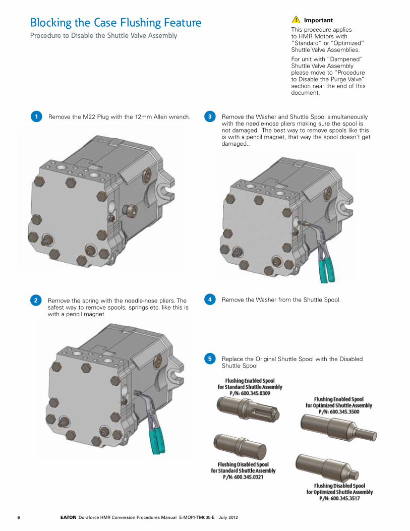
Blocking the Case Flushing FeatureProcedure to Disable the Shuttle Valve Assembly
Remove the M22 Plug with the 12mm Allen wrench.
Important
This procedure applies to HMR Motors with “Standard” or “Optimized” Shuttle Valve Assemblies.
For unit with “Dampened” Shuttle Valve Assembly please move to “Procedure to Disable the Purge Valve” section near the end of this document.
1
Remove the spring with the needle-nose pliers. The safest way to remove spools, springs etc. like this is with a pencil magnet
2
Remove the Washer and Shuttle Spool simultaneously with the needle-nose pliers making sure the spool is not damaged. The best way to remove spools like this is with a pencil magnet, that way the spool doesn't get damaged..
3
Remove the Washer from the Shuttle Spool.4
Replace the Original Shuttle Spool with the Disabled Shuttle Spool
5

7EATON Duraforce HMR Conversion Procedures Manual E-MOPI-TM005-E July 2012
Blocking the Case Flushing Feature Procedure to Disable the Shuttle Valve Assembly (continued)
Important
This procedure applies to HMR Motors with “Standard” or “Optimized” Shuttle Valve Assemblies. For unit with “Dampened” Shuttle Valve Assembly please move to “Procedure to Disable the Purge Valve” section near the end of this document.
Reinstall the Washer onto the Disabled Shuttle Spool.6
Reinstall the Washer/Disabled Shuttle Spool subassembly back into the Shuttle Body.
7
Reinstall the spring.8
Reinstall the M22 Plug. Torque the M22 Plug to 122 N-m (90 ft-lb).
9
8 EATON Duraforce HMR Conversion Procedures Manual E-MOPI-TM005-E July 2012
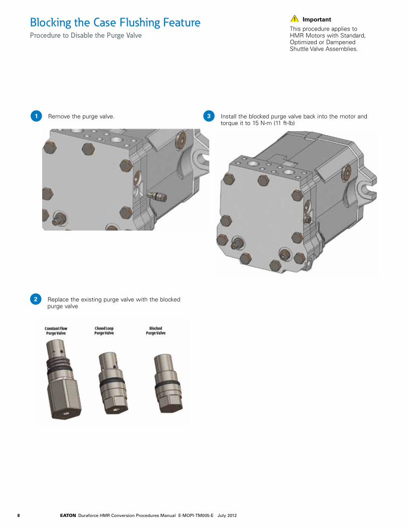
Blocking the Case Flushing FeatureProcedure to Disable the Purge Valve
Remove the purge valve.
Important
This procedure applies to HMR Motors with Standard, Optimized or Dampened Shuttle Valve Assemblies.
1
Replace the existing purge valve with the blocked purge valve
2
Install the blocked purge valve back into the motor and torque it to 15 N-m (11 ft-lb)
3

9EATON Duraforce HMR Conversion Procedures Manual E-MOPI-TM005-E July 2012
Closed LoopPurge Valve
Open LoopPurge Valve
Exchanging Purge Valves Set Up and Procedure
Procedure to Exchange a Closed Loop Purge Valve with an Open Loop Purge Valve
Remove the Closed Loop Purge Valve with the 13mm wrench.
Install the Open Loop Purge Valve and tighten it with the 17mm wrench. Torque it to 15 N-m (11 ft-lb).
Procedure to Exchange an Open Loop Purge Valve with a Closed Loop Purge Valve
Remove the Open Loop Purge Valve with the 17mm wrench.
Install the Closed Loop Purge Valve and tighten it with the 13mm wrench. Torque it to 15 N-m (11 ft-lb).
1
2
1
2
Note:
The open loop purge valve is slightly longer than the closed loop purge valve.

10 EATON Duraforce HMR Conversion Procedures Manual E-MOPI-TM005-E July 2012
Exchanging Shuttle Valve AssembliesSet Up
Important
Although these locations may differ from one unit type to the other, the internal parts are the same.
This procedure must be performed in a clean environment using clean Parts, Tools and Lubricants.
Important
The following image illustrates the different types of shuttle valve assemblies used on Eaton Hydraulics H** motors:
HMF75 HMR75 HMV75

11EATON Duraforce HMR Conversion Procedures Manual E-MOPI-TM005-E July 2012
Exchanging Shuttle Valve AssembliesDisassembly Procedure
Remove the plug from the shuttle valve assembly as shown here.
Note
An HMV motor is used to show the necessary steps throughout this document. The same process can be used for HMR motors.
1 In order to break loose the Loctite used to keep the shuttle body in place, heat the area directly above the shuttle assembly as shown here.
3
Remove the first set of shuttle spool, spring and shim combination.
2
Use the special Eaton tool to remove the shuttle body.4
Remove the remaining shuttle spool, spring and shim combination.
5
Important
There are three types of shuttle valve assemblies used on Eaton units and there are two different types of tools used to remove the shuttle bodies.
A better look at the shuttle valve assembly is shown below.
New Tool 600.880.0001

12 EATON Duraforce HMR Conversion Procedures Manual E-MOPI-TM005-E July 2012
Exchanging Shuttle Valve AssembliesAssembly Procedure
Apply Green Loctite 648 on the threads inside the rear head where the shuttle body will be installed.
Assemble the first set of shuttle spool/shim/spring into the shuttle body as shown during the training.
Insert the whole set into the shuttle cavity on the rear head and torque it using the special Eaton tool (refer to the torque chart at the bottom of this page)
Note
An HMV motor is used to show the necessary steps throughout this document. The same process can be used for HMR motors.
1 Install the plug and torque it (refer to the torque chart at the bottom of this page).
5
2
3
Insert the second set of shuttle spool/shim/spring into the shuttle body.
4
Item Description Torque Value ft-lb (N-m)
Standard shuttle body 100+7 (136+9)Dampened shuttle body 44+7 (60+9)Optimized shuttle body 44+7 (60+9)Shuttle cavity plug 90+7 (122+9)
Torque Chart

13EATON Duraforce HMR Conversion Procedures Manual E-MOPI-TM005-E July 2012
Position ofDisplacementOveride Bloack
Electric DOR
Pneumatic DOR
High Pressure DOR
S.H.C.S.(Typical)O-Ring(Typical)
Low Pressure DOR
Spring
Spool
Spool
Exchange Displacement Override BlocksSet Up and Procedure
Procedure to Exchange a Displacement Override (DOR) Block
Note
For the High-Pressure Hydraulic DOR configuration, there is a spool in the DOR housing. This spool should be kept with this DOR block. For the Pneumatic DOR configuration, there will be a spool and a spring in the DOR housing. This spool and spring should be kept with this DOR block.
Remove the four S.H.C.S. bolts from the existing DOR block with the 3mm Allen wrench. Keep the S.H.C.S. with the DOR being removed; Do NOT reused them with the new DOR block.
Remove the existing DOR block from the motor control. Make sure that the O-Ring is removed with the DOR block.
3 Prior to installing the new DOR block, check: a Make sure that the O-Ring is in good condition (i.e.
not damaged) and is resting properly in the o-ring groove.
b If the new DOR block is the High-Pressure Hydraulic DOR configuration, make sure that the Spool is there.
c If the new DOR block is the Pneumatic DOR con-figuration, make sure that the Spool and spring are there.
4 Install the new DOR block and fasten it with the four new S.H.C.S.; tighten the S.H.C.S. with the 3mm Allen wrench and torque each one to:
• 3.8 N-m (2.8 ft-lb) [For the Low-Pressure Hydraulic, High-Pressure Hydraulic, and Pneumatic DOR]
• 2.7 N-m (2.0 ft-lb) [For the Electric DOR].
1
2

14 EATON Duraforce HMR Conversion Procedures Manual E-MOPI-TM005-E July 2012
HMR Motor Controlwith Pressure Compensator,Electric DOR, and Brake Pressure Shut-off
S.H.C.S.(2 Places)
O-Ring (5 Places)
Standard HMR Motor Control with Pressure Compensator and DOR
Exchange Controls Set Up and Procedure
Procedure to Exchange Motor Controls
Note This procedure must be performed in a clean environment using clean Parts, Tools and Lubricants
Remove the existing motor control by removing the two S.H.C.S. with the 6mm Allen wrench. Keep the two S.H.C.S. for reuse.
Make sure to remove the five O-Rings with the existing control.
Prior to installing the new motor control, verify that the five O-Rings are in good condition (i.e not damaged) and are properly positioned in the O-Ring grooves.
Install the new motor control and fasten it with the two S.H.C.S. from step #1.
Tighten the S.H.C.S. with the 6mm Allen wrench and torque each one to 32 N-m (24 ft-lb).
1
2
3
4
5

15EATON Duraforce HMR Conversion Procedures Manual E-MOPI-TM005-E July 2012
Important
This procedure must be performed in a clean environment using clean Parts, Tools and Lubricants.
Exchanging Response Orifices on HMR MotorsSet Up and Procedure
Remove the four bolts that secure the control block as shown here.1
Remove the control block as shown here.2Note
Often, the o-rings from the bottom of the control block remain on the motor’s rear head. Make sure that all o-rings are removed from the rear head and installed on the control block.

16 EATON Duraforce HMR Conversion Procedures Manual E-MOPI-TM005-E July 2012
Remove the existing response orifices as shown here.
4
Response orifices are located at the bottom of the control block in the positions shown here.3 Install the new response orifices into the control block
as shown here.5
Position the control block on the motors rear head as shown here.
6
Exchanging Response Orifices on HMR Motors (continued)Set Up and Procedure
Important
Inspect all o-ring on the bottom of the control block; if necessary use petroleum jelly to secure them in position.
Install the mounting bolts and torque them to 32 N-m (24 ft-lb).
6
Important
Make sure to orient the control correctly so that all ports align with each other.

17EATON Duraforce HMR Conversion Procedures Manual E-MOPI-TM005-E July 2012
Rear-PortedHMR
Side-PortedHMR
MaximumDisplacementAdjustment(see note #1)
AdjustmentStud (Typical)
Seal Nut (Typical)
MaximumDisplacementAdjustment(see note #1)
Maximum Displacement Adjustment Procedure Set Up and Procedure
Procedure for Adjusting the HMR Maximum Displacement
Start the prime mover and adjust it to operating speed.
Actuate the HMR per the requirements stated in "Note #3".
To Adjust the Motor Maximum Displacement:
a. Hold the adjustment stud stationary with the 6mm Allen Wrench.
b. Loosen the seal nut with the 19mm wrench.
c. Turn the adjustment stud IN to decrease the maximum displacement or turn it OUT to increase the maximum displacement.
d. Once the desired maximum displacement has been acquired, hold the adjustment stud stationary with the 6mm Allen wrench and tighten the seal nut with the 19mm wrench. The proper torque for the seal nut is 60 N-m (44 ft-lb).
1
2
3
Note #1
All "side-ported" HMR motors have a maximum displacement adjustment. But NOT all "rear-ported" HMR motors have a maximum displacement adjustment. Depending on the specific configuration of your motor, it may or may not have a maximum displacement adjustment. For those HMR motors without a maximum displacement adjustment, please ignore this document.
Note #3
The HMR motors auto-matically default to minimum displacement unless:
• The motor is loaded beyond the regulation begin setting in which case the motor automatically shifts to maximum displacement then de-strokes to a displacement to accommodate the torque requirement (i.e. as the load pressure drops).
• Control pressure is supplied into the displacement override port thus forcing the HMR to maximum displacement.
Prior to adjusting the HMR maximum displacement, you must either:
• Provide means to supply control pressure into the displacement override port.
• Load the motor to create and maintain a pressure greater than the regulation begin setting being careful NOT to open the cross-over relief valves (if available).
Size 55 75 105 135 165
Max Displacement 54.8 75.9 105.0 135.6 165.0 Limit (CC) Continuous Max Speed at Max Speed Displacement 4100 3800 3500 3200 3100 (RPM) Continuous Max Speed at Min Displacement 4700 4400 4100 3700 3500
Note #2
The following table illustrates the maximum displacement limits and the maximum allowable rotational speeds for Both Max. and Min. displacements.

18 EATON Duraforce HMR Conversion Procedures Manual E-MOPI-TM005-E July 2012
Rear-PortedHMR
Side-PortedHMR Minimum
DisplacementAdjustment
AdjustmentStud (Typical)
Seal Nut (Typical)
MinimumDisplacementAdjustment
Minimum Displacement Adjustment ProcedureSet Up and Procedure
Procedure for Adjusting the HMR Minimum Displacement
Note To properly adjust the minimum displacement of the HMR motor, it is preferable that the motor free-spin while making the adjustment - This would insure that the motor was at minimum displacement.If this is not possible, then the HMR must be completely unloaded when making the minimum displacement adjustment to insure that it is at minimum displacement.
Start the prime mover and adjust it to operating speed.
Actuate the HMR motor under no load to insure it is at minimum displacement.
NoteThe HMR motor automatically defaults to minimum displacement unless:• The motor is loaded beyond the regulation begin setting in
which case the motor automatically shifts to a displacement to accommodate the torque requirement.
• Control pressure is supplied into the displacement override port thus forcing the HMR to maximum displacement.
To Adjust the Motor Minimum Displacement:
a. Hold the adjustment stud stationary with the 6mm Allen Wrench.
b. Loosen the seal nut with the 19mm wrench.
c. Turn the adjustment stud IN to increase the minimum displacement or turn it OUT to decrease the minimum displacement.
d. Once the desired minimum displacement has been acquired, hold the adjustment stud stationary with the 6mm Allen wrench and tighten the seal nut with the 19mm wrench. The proper torque for the seal nut is 60 N-m (44 ft-lb).
Note The following table illustrates the recommended minimum displacements and allowable rotational speeds for both Max. and Min. displacement. The HMR motors should NOT be operated at higher speeds if the recommended displacements are used, unless specifically approved by Eaton Engineering. If higher rotational speeds are required for your application, you must consult Eaton Engineering for the required minimum displacement setting.
1
2
3
Size 55 75 105 135 165
Max Displacement 18.3 25.3 35.0 45.2 55.2 Limit (CC) Continuous Max Speed at Max Speed Displacement 4100 3800 3500 3200 3100 (RPM) Continuous Max Speed at Min Displacement 4700 4400 4100 3700 3500

19EATON Duraforce HMR Conversion Procedures Manual E-MOPI-TM005-E July 2012
Procedure to Adjust Crossover Relief ValvesSet Up and Procedure
Procedure to Adjust Crossover Relief Valves
ImportantAll supplemental relief valves used in the same circuit as the Single-Setting Relief Valves must be set higher than the desired setting for the relief valves. This must be done prior to performing the steps in this Service Bulletin.
Install the pressure gauge or transducer to measure the pressure at Workport "A".
The function that the HMR motor actuates must be locked as to prevent the HMR- 02 motor from rotating. This will force oil to pass over the relief valve once oil is supplied to the HMR motor.
Supply flow to Workport "A". Only supply the maximum flow that the motor will receive during normal operation.
ImportantWhen pushing oil past the relief valve as described in step #3, the hydraulic oil and relief valve will heat up rapidly. Therefore, limit the timing in step #3 to 30 seconds or less. You should monitor the temperature of the hydraulic oil and HMR motor to ensure that they do NOT exceed 194°F (90°C). If the temperature of either reaches this maximum limit, stop all testing until the temperature cools off.
While supplying flow to Workport “A”, read the pressure on the gauge - This is the setting for the Workport "A" Relief Valve.
To adjust the Workport "A" Relief Valve pressure setting:
a. Refer to the illustrations on page 1 to make sure you are working on the correct relief valve.
b. Hold the Adjustment Stud stationary with the 5mm Allen wrench, and loosen the Seal Nut with the 17mm wrench.
c. Turn the Adjustment Stud IN to increase the relief valve pressure setting or OUT to decrease the relief valve pressure setting.
d. Once the desired pressure setting has been acquired, hold the Adjustment Stud stationary and tighten the Seal Nut. The proper torque for the Seal Nut is 60 N-m (44 ft-lb).
Then repeat steps #1 through #5 for Workport "B".
1
2
3
4
5
6
Workport “B”
Workport “B”
Workport “A”
Workport “A”
Workport “B”Relief Valve
VD20-04 Single SettingRelief Valves
VD20-04 Single SettingRelief Valves
Workport “A”Relief Valve
Workport “B”Relief Valve
Workport “A”Relief Valve
Adjustment Stud
Adjustment Stud
Seal Nut
Seal Nut
Workport “B”
Workport “B”
Workport “A”
Workport “A”
Workport “B”Relief Valve
VD20-04 Single SettingRelief Valves
VD20-04 Single SettingRelief Valves
Workport “A”Relief Valve
Workport “B”Relief Valve
Workport “A”Relief Valve
Adjustment Stud
Adjustment Stud
Seal Nut
Seal Nut

20 EATON Duraforce HMR Conversion Procedures Manual E-MOPI-TM005-E July 2012
Operational ParametersLifetime Recommendations
Eaton high pressure units are designed for excellent reliability and long service life. The actual service life of a hydraulic unit is determined by numerous factors. It can be extended significantly through proper maintenance of the hydraulic system and by using high-quality hydraulic fluid.
Beneficial Conditions For Long Service Life
Speed Lower continuous maximum speedOperating Pressure Less than 300 bar Δp on averageMaximum Pressure Only at reduced displacementViscosity 15 ... 30 cStPower Continuous power or lowerPurity of Fluid 18/16/13 in accordance with ISO 4406 or better
Adverse Factors Affecting Service Life
Speed Between continuous maximum speed and intermittent maximum speed
Operating Pressure More than 300 bar Δp on average
Viscosity Less than 10 cSt
Power Continuous operation close to maximum power
Purity of Fluid Lower than 18/ 16/ 13 in accordance with ISO 4406
Filtration
For Reliable Proper Function and Long Service Life 18/16/13 in accordance with ISO 4406 or betterMinimum Requirements 20/18/15 in accordance with ISO 4406Commissioning The minimum purity requirement for the hydraulic oil is based on the most sensitive
system component. For commissioning we recommend a filtration in order to achieve the required purity.
Filing in Operation of Hydraulic Systems The required purity of the hydraulic oil must be ensured during filling or topping up. When drums, canisters or large-capacity tanks are used the oil generally has to be filtered. We recommend the implementation of suitable measures (e.g. filters) to ensure that the required minimum purity of the oil is also achieved during operation
International Standard Code number according to ISO 4406 purity class according to SAE AS 4059 18/16/13 corresponds to 8A/7B/7C 20/18/15 9A/8B/8C
Operational parameters. Filtration
In order to guarantee long-term proper function and high efficiency of the hydraulic pumps the
cleanliness level of the lubricant must comply with the following criteria according to
Eaton Hydraulic Fluid Recommendation 03-401-2010. Maintaining the recommended cleanliness
level can extend the service life of the hydraulic system significantly.
For reliable proper function and long service life
18/16/13 in accordance with ISO 4406 or better
Commissioning
The minimum cleanliness level requirement for the hydraulic oil is based on the most sensitive component. For commissioning we recommend a filtration in order to achieve the required cleanliness level.
Filling and operation of hydraulic systems
The required cleanliness level of the hydraulic oil must be ensured during filling or topping up. When drums, canisters, or large-capacity tanks are used the oil generally has to be filtered. We recommend the implementation of suitable filters to ensure that the required cleanliness level of the oil is achieved and maintained during operation.
International standard Code number according to ISO 440618/16/13

21EATON Duraforce HMR Conversion Procedures Manual E-MOPI-TM005-E July 2012
Operational ParametersPressure Fluids
In order to ensure the functional performance and high efficiency of the hydraulic motors the viscosity and purity of the operating fluid should meet the different operational requirements. Eaton recommends using only hydraulic fluids which are confirmed by the manufacturer as suitable for use in high pressure hydraulic installations or approved by the original equipment manufacturer.
• Mineral oil HLP to DIN 51 524-2
• Biodegradable fluids in accordance with ISO 15 380 on request
• Other pressure fluids on request
Eaton offers an oil testing service in accordance with VDMA 24 570 and the test apparatus required for in-house testing. Prices available on request.
Pressure Fluid Temperature Range [°C] -20 to +90
Working viscosity range [mm²/s] = [cSt] 10 to 80Optimum working viscosity [mm²/s] = [cSt] 15 to 30Max. viscosity (short time start up) [mm²/s] = [cSt] 1000
Permitted Pressure Fluids
Recommended Viscosity Ranges
Viscosity Recommendations
In order to be able to select the right hydraulic fluid it is necessary to know the working temperature in the hydraulic circuit. The hydraulic fluid should be selected such that its optimum viscosity is within
the working temperature range (see tables).
The temperature should not exceed 90°C (194°F) in any part of the system. Due to pressure and speed influences the
leakage fluid temperature is always higher than the circuit temperature. Please contact Eaton if the stated conditions cannot be met in special circumstances.
Working Temperature Viscosity Class
Temperature [mm²/s] = [cSt] at 40°C (104°F)
Approx. 30 to 40°C (86 to 104°F) 22Approx. 40 to 60°C (104 to 140°F) 32Approx. 60 to 80°C (140 to 176°F) 46 or 68
Further information regarding installation can be found in the operating instructions.

22 EATON Duraforce HMR Conversion Procedures Manual E-MOPI-TM005-E July 2012
Eaton Part NumbersHMR Regulated Variable Displacement Motors (Open & Closed Loop Operation)
Part # Description Qty
6003435526 Plug 10009630107 O-ring 1
Blocking Purge Valves p. 8
Part # Description Qty
0009630107 O-ring 16003451030 Valve Sleeve 16003450352 Valve Piston 10009210910 Compression Spring 19289003013 Shim, 0.5mm as req'd9289003010 Shim, 0.1mm as req'd6003435528 Screw Plug 1
Purge Valves - Open Loop p. 9
Part # Description Qty
0009630107 O-ring 16003451008 Valve Sleeve 19516003252 Ball 10009211007 Spring 19289003006 Shim, 0.5mm as req'd9289003003 Shim, 0.1mm as req'd6003435512 Screw Plug 1
Purge Valves - Closed Loop, 10 bar Standard p. 9
Part # Description Qty
0009630107 O-ring 16003451008 Valve Sleeve 19516003252 Ball 10009211007 Spring 19289003006 Shim, 0.5mm as req'd9289003003 Shim, 0.1mm as req'd6003435512 Screw Plug 16003454000 Orifice 1
Purge Valves - Closed Loop, 10 bar Reduced p. 9
Part # Description Qty
Standard6003405642 Standard Shuttle 1Dampened6003405620 Dampened Shuttle 1Optimized6003405651 Optimized Shuttle 1
Shuttle Valves p. 10
Part # Description Qty
0009630107 O-ring 16003451008 Valve Sleeve 19516003252 Ball 10009211009 Spring 19289003006 Shim, 0.5mm as req'd9289003003 Shim, 0.1mm as req'd6003435512 Screw Plug 1
Purge Valves - Closed Loop, 14 bar Standard p. 9
Part # Description Qty
0009630107 O-ring 16003451008 Valve Sleeve 19516003252 Ball 10009211009 Spring 19289003006 Shim, 0.5mm as req'd9289003003 Shim, 0.1mm as req'd6003435512 Screw Plug 16003454000 Orifice 1
Purge Valves - Closed Loop, 14 bar Reduced p. 9

23EATON Duraforce HMR Conversion Procedures Manual E-MOPI-TM005-E July 2012
Eaton Part NumbersHMR Regulated Variable Displacement Motors (Open & Closed Loop Operation)
Part # Description Qty
0009632216 O-ring 10009736085 Coil, 12V AMP 19045311086 Cap Screw 4
Displacement Override Block (DOR) - Electric, 12V AMP p. 13
Part # Description Qty
0009632216 O-ring 15863410100 Housing, DIN Port 15863450300 Valve Piston 10009620177 Screw Plug 19045341077 Cap Screw 4
Displacement Override Block (DOR) - High Pressure, DIN Port p. 13
Part # Description Qty
5863400739 Low Pressure, DIN Port 15863400743 Low Pressure, ISO Port 15863400738 High Pressure, DIN Port 15863400742 High Pressure, ISO Port 15863400714 Through Brake Valve 15863400734 Electrically Switched, 12V DIN 15863400735 Electrically Switched, 12V AMP 1
Controls - p. 14
Part # Description Qty
0009037005 Orifice, 0.6mm 20009037052 Orifice, 0.7mm 20009037047 Orifice, 0.8mm 20009037033 Orifice, 0.9mm 20009037045 Orifice, 1.0mm 20009037050 Orifice, 1.2mm 20009037046 Orifice, 1.5mm 20009037511 Orifice, 1.8mm 20009037510 Orifice, 2.1mm 2
O-rings for Controls - p. 14
Part # Description Qty
0009632216 O-ring 10009736008 Coil, 12V DIN 17915001590 Seal for DIN Plug 10009750508 DIN Plug 19045311086 Cap Screw 4
Displacement Override Block (DOR) - Electric, 12V DIN p. 13
Part # Description Qty
0009632216 O-ring 10009736009 Coil, 24V DIN 17915001590 Seal for DIN Plug 10009750508 DIN Plug 19045311086 Cap Screw 4
Displacement Override Block (DOR) - Electric, 24V DIN p. 13
Part # Description Qty
0009632216 O-ring 1586340102 Housing, ISO Port 15863450300 Valve Piston 10009620177 Screw Plug 19045341077 Cap Screw 4
Displacement Override Block (DOR) - High Pressure, ISO Port p. 13
Part # Description Qty
0009632216 O-ring 15863433500 Flange, DIN Port 10009620177 Screw Plug 19045341071 Cap Screw 4
Displacement Override Block (DOR) - Low Pressure, DIN Port p. 13
Part # Description Qty
0009632216 O-ring 15863433501 Flange, ISO Port 10009620177 Screw Plug 19045341071 Cap Screw 4
Displacement Override Block (DOR) - Low Pressure, ISO Port p. 13

EatonHydraulics Group USA14615 Lone Oak RoadEden Prairie, MN 55344USATel: 952-937-9800Fax: 952-294-7722www.eaton.com/hydraulics
EatonHydraulics Group EuropeRoute de la Longeraie 71110 MorgesSwitzerlandTel: +41 (0) 21 811 4600Fax: +41 (0) 21 811 4601
Eaton Hydraulics Group Asia PacificEaton BuildingNo.7 Lane 280 Linhong Road Changning District, Shanghai200335 ChinaTel: (+86 21) 5200 0099Fax: (+86 21) 2230 7240
© 2012 Eaton CorporationAll Rights Reserved Printed in USADocument No. E-MOPI-TM005-EJuly 2012