ece 382 lesson 14 lesson outline polling multiplexing intro to logic analyzer debouncing software...
TRANSCRIPT

ECE 382 Lesson 14
Lesson OutlinePolling
Multiplexing
Intro to Logic Analyzer
Debouncing
Software Delay Routines
Admin
Assignment 3b due BOC today
Assignment 4 due BOC next class

Interfacing Peripherals to the MCU
• What is Polling?• What are Interrupts? bic.b #BIT3, &P1DIR bis.b #BIT3, &P1REN bis.b #BIT3, &P1OUT
poll_button: bit.b #BIT3, &P1IN jnz poll_button
forever jmp forever

HomeworkModify this program so the two LEDs always have the opposite value
bis.b #BIT0|BIT6, &P1DIR ; output pin direction bic.b #BIT3, &P1DIR ; input pin direction bis.b #BIT3, &P1REN ; enable pin 3’s resistor bis.b #BIT3, &P1OUT ; make it a pull-up? (trick)
check_btn: bit.b #BIT3, &P1IN jz set_lights bic.b #BIT0|BIT6, &P1OUT jmp check_btnset_lights: bis.b #BIT0|BIT6, &P1OUT jmp check_btn

Pitfall !!!
• Anything wrong with this?
– mov.b #0xff, P1DIR
• What do these commands do?– mov.b #0b00001111, &P1DIR– bis.b #0b00001111, &P1OUT– mov.b #0xff, &P1OUT– mov.b &P1IN, r5

Multiplexing• Only 20 Pins !!! But want access to many more signals
– Therefore, each pin shares several signals multiplexing
• Use PxSEL1 and PxSEL2 to select signal for each pin– The details are in the MSP430G2x53 2x13 Mixed Signal MCU Datasheet
.

Pitfall !!!
Let's say I wanted to make the UCA0SOMI function available on P1.1:– ; 'from USCI' means this bit is set automatically by the USCI when enabled– bis.b #BIT1, P1SEL – bis.b #BIT1, P1SEL2
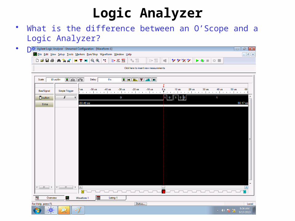
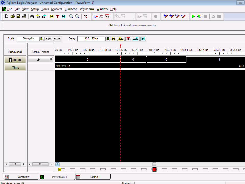
Logic Analyzer• What is the difference between an O’Scope and a Logic Analyzer?• Debouncing?

Logic Analyzer• Debouncing: random bounces each time…

Is bouncing a problem?
bis.b #BIT3, &P1OUT bis.b #BIT3, &P1REN bic.b #BIT3, &P1DIR
clr r4
check_btn: bit.b #BIT3, &P1IN jz btn_pushed jmp check_btn
btn_pushed: inc r4wait: bit.b #BIT3, &P1IN jz wait inc r4 jmp check_btn

Debouncing Strategies• How can we fix this?

Debouncing Strategies• How can we fix this?
– There is hardware debouncing– And there is software debouncing:
• Delay until bouncing has stopped– with a Software Delay Routine
or– with a Hardware Counter
• Then resume
• What are some potential problems with this?

Debouncing Strategies• How can we fix this?
– There is hardware debouncing– And there is software debouncing:
• Delay until bouncing has stopped– with a Software Delay Routine
or– with a Hardware Counter
• Then resume
• What are some potential problems with this? – You could delay for too short a period and still be impacted by bouncing.– You could delay for too long a period and miss good button pushes

Example Software Delay Routine
How long is this software delay?
call #software_delay
software_delay: push r5 mov.w #0xaaaa, r5delay: dec r5 jnz delay pop r5 ret
MSP430 Family Users Guide, p 60 for cycles per instruction

Example Software Delay Routine
How long is this software delay?
call #software_delay ; 5 cycles
software_delay: push r5 ; 3 cycles mov.w #0xaaaa, r5 ; 2 cyclesdelay: dec r5 ; 2 cycles ; no 1 cycle !!! jnz delay ; 2 cycles pop r5 ; 2 cycles ret ; 2 cycles ; no 3 cycles !!!
5 + 3 + 2 + (0xaaaa * (1 + 2)) + 2 + 3 = 131085 total clock cycles
Only variable is r5… if I change r5 by “one”, how many cycles is this?
(ie., precision of delay?)
So, How long in time is this?

MSP430’s Digitally Controlled Oscillator • MSP430’s Clock = Digitally Controlled Oscillator (DCO)
– Advantage: It is tunable. Can run at many different frequencies– Disadvantage: It is an RC oscillator, so can be inaccurate– Default: 1 MHz, with significant variance (0.8MHz - 1.5MHz) – Fix: At the factory, each chip is calibrating with a more accurate quartz crystal resonator. TI
stores the proper calibrated values for DCOCTL and BCSCTL1 for 1MHz, 8MHz, 12MHz, and 16MHz in protected memory.
• We can measure clock speed (SMCLK) on P1.4
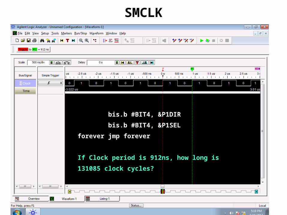
SMCLK
bis.b #BIT4, &P1DIR
bis.b #BIT4, &P1SEL
forever jmp forever
If Clock period is 912ns, how long is
131085 clock cycles?
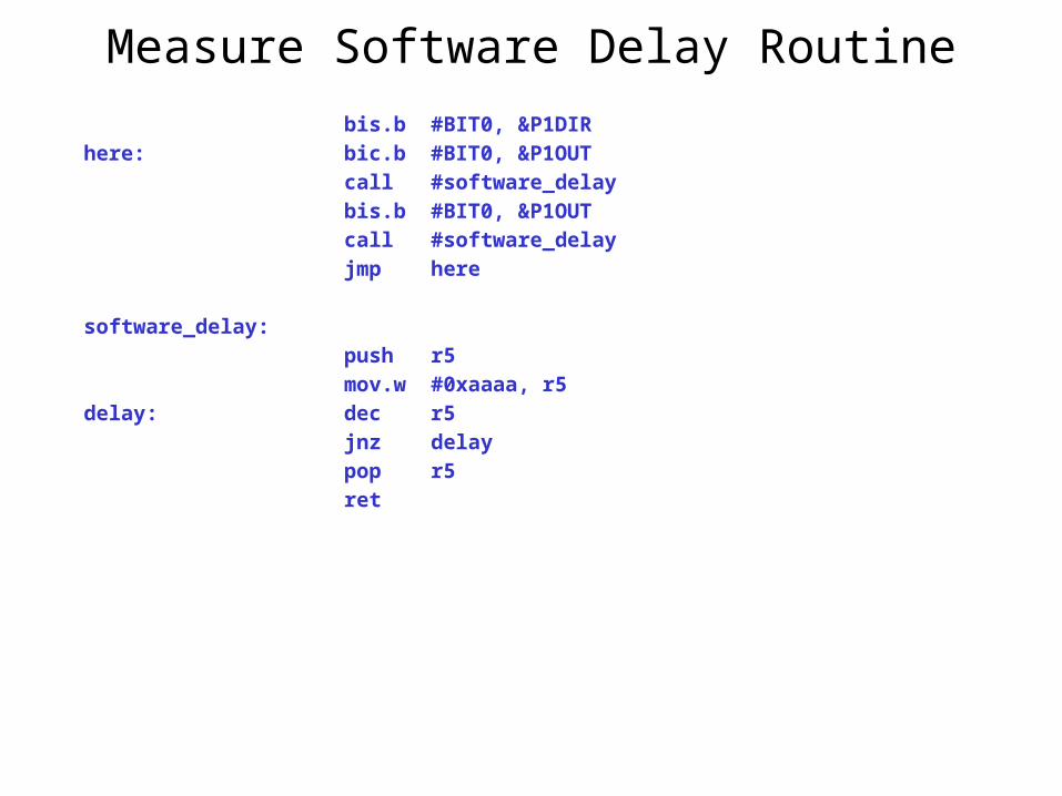
Measure Software Delay Routine
bis.b #BIT0, &P1DIRhere: bic.b #BIT0, &P1OUT call #software_delay bis.b #BIT0, &P1OUT call #software_delay jmp here
software_delay: push r5 mov.w #0xaaaa, r5delay: dec r5 jnz delay pop r5 ret

Measure SW delay routine
bis.b #BIT4, &P1DIR
bis.b #BIT4, &P1SEL
forever jmp forever
If Clock period is 912ns, how long is
131085 clock cycles?

Debounced code with SW delay bis.b #BIT3, &P1OUT bis.b #BIT3, &P1REN bic.b #BIT3, &P1DIR
check_btn: bit.b #BIT3, &P1IN jnz check_btn call #software_delay jmp btn_pushed
btn_pushed: bit.b #BIT3, &P1IN jz btn_pushed call #software_delay jmp check_btn
software_delay: push r5 mov.w #0xaaaa, r5delay: dec r5 jnz delay pop r5 ret